EP4401422A1 - Anzeigevorrichtung für die frontabstrahlung von audio - Google Patents
Anzeigevorrichtung für die frontabstrahlung von audio Download PDFInfo
- Publication number
- EP4401422A1 EP4401422A1 EP22901518.5A EP22901518A EP4401422A1 EP 4401422 A1 EP4401422 A1 EP 4401422A1 EP 22901518 A EP22901518 A EP 22901518A EP 4401422 A1 EP4401422 A1 EP 4401422A1
- Authority
- EP
- European Patent Office
- Prior art keywords
- frame
- display device
- speaker
- housing
- state
- Prior art date
- Legal status (The legal status is an assumption and is not a legal conclusion. Google has not performed a legal analysis and makes no representation as to the accuracy of the status listed.)
- Pending
Links
Images







Classifications
-
- H—ELECTRICITY
- H04—ELECTRIC COMMUNICATION TECHNIQUE
- H04R—LOUDSPEAKERS, MICROPHONES, GRAMOPHONE PICK-UPS OR LIKE ACOUSTIC ELECTROMECHANICAL TRANSDUCERS; ELECTRIC HEARING AIDS; PUBLIC ADDRESS SYSTEMS
- H04R5/00—Stereophonic arrangements
- H04R5/02—Spatial or constructional arrangements of loudspeakers
-
- H—ELECTRICITY
- H04—ELECTRIC COMMUNICATION TECHNIQUE
- H04R—LOUDSPEAKERS, MICROPHONES, GRAMOPHONE PICK-UPS OR LIKE ACOUSTIC ELECTROMECHANICAL TRANSDUCERS; ELECTRIC HEARING AIDS; PUBLIC ADDRESS SYSTEMS
- H04R1/00—Details of transducers, loudspeakers or microphones
- H04R1/20—Arrangements for obtaining desired frequency or directional characteristics
- H04R1/22—Arrangements for obtaining desired frequency or directional characteristics for obtaining desired frequency characteristic only
- H04R1/28—Transducer mountings or enclosures modified by provision of mechanical or acoustic impedances, e.g. resonator, damping means
- H04R1/2807—Enclosures comprising vibrating or resonating arrangements
- H04R1/2853—Enclosures comprising vibrating or resonating arrangements using an acoustic labyrinth or a transmission line
- H04R1/2857—Enclosures comprising vibrating or resonating arrangements using an acoustic labyrinth or a transmission line for loudspeaker transducers
-
- H—ELECTRICITY
- H04—ELECTRIC COMMUNICATION TECHNIQUE
- H04N—PICTORIAL COMMUNICATION, e.g. TELEVISION
- H04N5/00—Details of television systems
- H04N5/64—Constructional details of receivers, e.g. cabinets or dust covers
-
- H—ELECTRICITY
- H04—ELECTRIC COMMUNICATION TECHNIQUE
- H04N—PICTORIAL COMMUNICATION, e.g. TELEVISION
- H04N5/00—Details of television systems
- H04N5/64—Constructional details of receivers, e.g. cabinets or dust covers
- H04N5/642—Disposition of sound reproducers
-
- H—ELECTRICITY
- H04—ELECTRIC COMMUNICATION TECHNIQUE
- H04R—LOUDSPEAKERS, MICROPHONES, GRAMOPHONE PICK-UPS OR LIKE ACOUSTIC ELECTROMECHANICAL TRANSDUCERS; ELECTRIC HEARING AIDS; PUBLIC ADDRESS SYSTEMS
- H04R1/00—Details of transducers, loudspeakers or microphones
- H04R1/02—Casings; Cabinets ; Supports therefor; Mountings therein
- H04R1/025—Arrangements for fixing loudspeaker transducers, e.g. in a box, furniture
-
- H—ELECTRICITY
- H04—ELECTRIC COMMUNICATION TECHNIQUE
- H04R—LOUDSPEAKERS, MICROPHONES, GRAMOPHONE PICK-UPS OR LIKE ACOUSTIC ELECTROMECHANICAL TRANSDUCERS; ELECTRIC HEARING AIDS; PUBLIC ADDRESS SYSTEMS
- H04R1/00—Details of transducers, loudspeakers or microphones
- H04R1/02—Casings; Cabinets ; Supports therefor; Mountings therein
- H04R1/028—Casings; Cabinets ; Supports therefor; Mountings therein associated with devices performing functions other than acoustics, e.g. electric candles
-
- H—ELECTRICITY
- H04—ELECTRIC COMMUNICATION TECHNIQUE
- H04R—LOUDSPEAKERS, MICROPHONES, GRAMOPHONE PICK-UPS OR LIKE ACOUSTIC ELECTROMECHANICAL TRANSDUCERS; ELECTRIC HEARING AIDS; PUBLIC ADDRESS SYSTEMS
- H04R1/00—Details of transducers, loudspeakers or microphones
- H04R1/20—Arrangements for obtaining desired frequency or directional characteristics
- H04R1/32—Arrangements for obtaining desired frequency or directional characteristics for obtaining desired directional characteristic only
- H04R1/34—Arrangements for obtaining desired frequency or directional characteristics for obtaining desired directional characteristic only by using a single transducer with sound reflecting, diffracting, directing or guiding means
- H04R1/345—Arrangements for obtaining desired frequency or directional characteristics for obtaining desired directional characteristic only by using a single transducer with sound reflecting, diffracting, directing or guiding means for loudspeakers
-
- H—ELECTRICITY
- H04—ELECTRIC COMMUNICATION TECHNIQUE
- H04R—LOUDSPEAKERS, MICROPHONES, GRAMOPHONE PICK-UPS OR LIKE ACOUSTIC ELECTROMECHANICAL TRANSDUCERS; ELECTRIC HEARING AIDS; PUBLIC ADDRESS SYSTEMS
- H04R1/00—Details of transducers, loudspeakers or microphones
- H04R1/20—Arrangements for obtaining desired frequency or directional characteristics
- H04R1/32—Arrangements for obtaining desired frequency or directional characteristics for obtaining desired directional characteristic only
- H04R1/40—Arrangements for obtaining desired frequency or directional characteristics for obtaining desired directional characteristic only by combining a number of identical transducers
-
- H—ELECTRICITY
- H04—ELECTRIC COMMUNICATION TECHNIQUE
- H04R—LOUDSPEAKERS, MICROPHONES, GRAMOPHONE PICK-UPS OR LIKE ACOUSTIC ELECTROMECHANICAL TRANSDUCERS; ELECTRIC HEARING AIDS; PUBLIC ADDRESS SYSTEMS
- H04R1/00—Details of transducers, loudspeakers or microphones
- H04R1/20—Arrangements for obtaining desired frequency or directional characteristics
- H04R1/32—Arrangements for obtaining desired frequency or directional characteristics for obtaining desired directional characteristic only
- H04R1/40—Arrangements for obtaining desired frequency or directional characteristics for obtaining desired directional characteristic only by combining a number of identical transducers
- H04R1/403—Arrangements for obtaining desired frequency or directional characteristics for obtaining desired directional characteristic only by combining a number of identical transducers loud-speakers
-
- H—ELECTRICITY
- H04—ELECTRIC COMMUNICATION TECHNIQUE
- H04R—LOUDSPEAKERS, MICROPHONES, GRAMOPHONE PICK-UPS OR LIKE ACOUSTIC ELECTROMECHANICAL TRANSDUCERS; ELECTRIC HEARING AIDS; PUBLIC ADDRESS SYSTEMS
- H04R7/00—Diaphragms for electromechanical transducers; Cones
- H04R7/02—Diaphragms for electromechanical transducers; Cones characterised by the construction
- H04R7/04—Plane diaphragms
-
- H—ELECTRICITY
- H04—ELECTRIC COMMUNICATION TECHNIQUE
- H04R—LOUDSPEAKERS, MICROPHONES, GRAMOPHONE PICK-UPS OR LIKE ACOUSTIC ELECTROMECHANICAL TRANSDUCERS; ELECTRIC HEARING AIDS; PUBLIC ADDRESS SYSTEMS
- H04R2499/00—Aspects covered by H04R or H04S not otherwise provided for in their subgroups
- H04R2499/10—General applications
- H04R2499/15—Transducers incorporated in visual displaying devices, e.g. televisions, computer displays, laptops
-
- H—ELECTRICITY
- H04—ELECTRIC COMMUNICATION TECHNIQUE
- H04R—LOUDSPEAKERS, MICROPHONES, GRAMOPHONE PICK-UPS OR LIKE ACOUSTIC ELECTROMECHANICAL TRANSDUCERS; ELECTRIC HEARING AIDS; PUBLIC ADDRESS SYSTEMS
- H04R9/00—Transducers of moving-coil, moving-strip, or moving-wire type
- H04R9/06—Loudspeakers
Definitions
- the present disclosure relates to a display device for front emission of audio.
- a display device may include a display panel to provide visual information to a user. Visual information that may be viewed by a user may be displayed in the display area of the display panel. A user of the display device may view visual information displayed on the display area in a direction toward which the display area faces.
- the display device may include a speaker module to provide audio along with visual information to the user.
- the user may be provided with audio through the speaker module.
- the display device may be disposed at a specific location for viewing by the user.
- the display device may be installed on a wall, a ceiling, or a pillar, and may be disposed on the ground or a table.
- the speaker module disposed inside the display device may have a structure that emits audio toward the top and bottom of the display device rather than the direction the display panel faces.
- the audio emitted the top and bottom of the display device may be degraded or distorted in sound quality depending on the structure of the indoor space in which the display device is disposed. For example, when audio is emitted toward the top of the display device, the audio may be reflected from the ceiling and then transmitted to the user, thereby reducing the resolution of the audio.
- a specific posture of the display device may be different. For example, a stand-up display device may be preferred in a large space, and a wall-mounted display device may be preferred in a narrow space. When changing the posture is impossible when the display device is moved from one space to another, it may cause inconvenience to the user.
- Various embodiments of the present disclosure may provide a display device capable of transmitting clear and high-resolution audio and freely changing posture.
- a display device may comprise a display panel; a housing comprising a first frame comprising a plate to support the display panel and a second frame integrally formed with the first frame, the second frame being formed to extend from one periphery of the first frame along a direction toward which the display area of the display panel faces; a speaker module including at least one speaker and disposed in the second frame; and a circuit board on the second frame and to be operatively connected to the display panel and the speaker; wherein the second frame may comprise a slit on an outer surface of the second frame that faces the direction along which the second frame is formed to extend to allow audio emitted from the speaker to be transmitted along the direction toward which the display area faces.
- various embodiments may be possible.
- a display device may comprise a display panel; a housing including a first frame comprising a plate to support the display panel and a second frame integrally formed with the first frame, the second frame being formed to extend from one periphery of the first frame along a direction toward which the display area of the display panel faces; a speaker module including at least one speaker and disposed in the second frame; a posture detection sensor within the housing that identifies a posture of the housing; and one or more processors within the second frame that changes visual information provided through the display area based on a signal obtained from the posture detection sensor.
- the display device can provide clear and high-resolution audio to the user through a structure capable of directly transmitting audio to the user.
- the display device can change a posture, and may provide substantially the same visual signal and substantially the same audio depending on the change of the posture.
- the display device can secure an indoor space by selecting a free posture according to the indoor space in which the display device is installed and the user's preference.
- a circuit board for driving the display device is disposed close to the display driver integrated circuit, it can be easy to design for electrical connection between the circuit board and the display driver integrated circuit.
- FIG. 1 is a block diagram of a display device according to an embodiment.
- the display device 100 may be implemented as various devices capable of playing image content by including a display such as, for example, a smart TV, a tablet, a monitor, a smart phone, a desktop computer, a laptop computer, a navigation, and a digital signage.
- the display device 100 may further include various other configurations required for the operation of the implemented device in addition to the configuration illustrated in FIG. 1 , according to the implementation example.
- the display panel 110 may display visual information (e.g., multimedia data or text data) to a user.
- the display panel 110 may include a display area for displaying visual information.
- the display panel 110 may have various configurations and structures capable of implementing an image.
- the display panel 110 may include a plurality of pixels, and each pixel may include a plurality of sub-pixels.
- each pixel may include three sub-pixels corresponding to a plurality of light, for example, red, green, and blue(R, G, and B) light.
- the pixel may include a first sub-pixel providing red light, a second sub-pixel providing blue light, a third sub-pixel providing green light, and a fourth sub-pixel.
- the present invention is not limited thereto, and in some cases, Cyan, Magenta, Yellow, Black, or other sub-pixels may be included in addition to the red, green, and blue sub-pixels.
- the display panel 110 may be a liquid crystal display (LCD), a plasma display panel (PDP), an organic light emitting display (OLED), an electric field emission display (FED), or white organic light emitting display(WOLED).
- the display panel 110 may be planar or curved.
- the one or more processors 120 may control at least one other component (e.g., hardware or software component) of the display device 100 connected to the one or more processors 120, and perform various data processing or operations.
- the one or more processors 120 may store commands or data received from other components (e.g., sensors 140) in the volatile memory, process commands or data stored in the volatile memory, and store the result data in the non-volatile memory.
- the one or more processors 120 may control the overall operation of the display device 100.
- the one or more processors 120 may be implemented as a digital signal processor(DSP) 120, a microprocessor 120, and a time controller (TCON).
- DSP digital signal processor
- MCU micro controller unit
- MPU micro processing unit
- AP application processor
- GPU graphics-processing unit
- CP communication processor
- ARM processor 120 ARM processor
- the one or more processors 120 may be implemented as a system on chip (SoC) or a large scale integration (LSI) in which a processing algorithm is embedded, or may be implemented in the form of a field programmable gate array (FPGA).
- SoC system on chip
- LSI large scale integration
- FPGA field programmable gate array
- the memory 130 may store various data used by at least one component (e.g., one or more processors 120 or sensor 140) of the display device 100.
- the data may include, for example, input data or output data for software and related commands.
- the memory 130 may store data for driving the display device 100, an application, an operating system (O/S), and/or an algorithm.
- the memory 130 may store various information such as various data input, set, or generated during execution of a program or application.
- the one or more processors 120 may perform various functions by executing computer executable instructions stored in the memory 130.
- the memory 130 may include a volatile memory or a non-volatile memory.
- the input/output interface 150 may transmit a command or data input from a user to the one or more processors 120 and/or the memory 130.
- the input/output interface 150 may be provided to be connectable to another device separately provided from the display device 100, for example, an external storage device.
- the input/output interface 150 may be a universal serial bus (USB) terminal, and in addition, may include at least one of various interface terminals such as a high definition multimedia interface (HDMI) terminal or a Thunderbolt terminal.
- HDMI high definition multimedia interface
- Thunderbolt terminal Thunderbolt terminal
- the broadcast receiver 160 may receive a broadcast signal from a broadcast station or a satellite by wire or wirelessly.
- the broadcast receiver 160 may receive and demodulate a transmission stream through an antenna or a cable to output a digital transmission stream signal.
- the broadcast receiver 160 may be omitted.
- the speaker module 170 by converting into sound, may output an audio signal received from the outside and/or an audio signal (e.g., a notification sound, a voice message) generated by the display device 100.
- the speaker module 170 may include at least one speaker.
- the speaker module 170 may output a stereophonic sound by each audio signal corresponding to each speaker.
- speaker module 170 includes a first speaker (e.g., a first speaker 231 of FIG. 7 ) and a second speaker (e.g., a second speaker 231 of FIG. 7 ) spaced apart from display device 100, and each speaker may provide a three-dimensional sound to a user by outputting different audio signals.
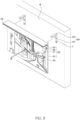
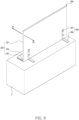
- FIG. 2 illustrates a first state of a display device according to an embodiment.
- a display device 200 may include a display panel 210 that provides visual information to a user, a housing 220 including a first frame 221 and a second frame 223, and a speaker module 230 that provides audio to a user by outputting an audio signal, a circuit board 240 for controlling the display device 200 and supplying power to the display device 200 and a slit 250 disposed in a second frame 223.
- the display panel 210 may include a display area 211 that displays visual information.
- the display panel 210 may provide visual information to a user through the display area 211.
- the display panel 210 may provide an image signal provided from the broadcast receiver to the user through the display area 211.
- the display area 211 of the display panel 210 may be divided at a predetermined ratio according to a user's setting.
- the display panel 210 may include a plurality of pixels. A pixel may mean a minimum unit composing an image when the image is visually displayed through light emitted from a light source of the display panel 210.
- the housing 220 may include a first frame 221 and a second frame 223.
- the first frame 221 may include a plate supporting one surface of the display panel 210.
- the first frame 221 may correspond to the shape of the display panel 210.
- an area of the first frame 221 that supports the display panel 210 may be a planar plate.
- at least a part of the first frame 221 that supports the display panel 210 may be bent to correspond to the shape of the display panel 210.
- the second frame 223 may be integrally formed with the first frame 221.
- the fact that the first frame 221 and the second frame 223 are integrally formed may mean a structure in which the first frame 221 and the second frame 223 are directly connected, without a separate connecting member connecting the first frame 221 and the second frame 223.
- the housing 220 may include a bent second frame 223 at one periphery 222 of the first frame 221.
- the second frame 223 may extend from one periphery 222 of the first frame 221 in a direction D1 in which the display area 211 of the display panel 210 faces.
- the direction D1 in which the display area 211 of the display panel 210 faces may refer to an emission direction of light emitted from the display panel 210.
- the display device 200 may be capable of changing the posture of the housing 220.
- the posture of the housing 220 may include a first state and a second state that may be distinguished according to a position of the second frame 223 with respect to the first frame 221.
- the first state of the display device 200 may mean a state in which the second frame 223 is positioned above the first frame 221. The first state may be distinguished from the second state to be described later.
- the display device 200 may be installed on an external object in the first state.
- the display device 200 may be used as a wall-hanging display device 200 installed on a wall, ceiling, or pillar in the first state.
- the first frame 221 may be in contact with the wall, and the second frame 223 may protrude from the wall contacting the first frame 221 in a direction D1 in which the display area 211 of the display panel 210 faces. Since the second frame 223 protrudes in the direction D1 in which the display area 211 faces, the second frame 223 may protrude in a direction opposite to a position of an external object (e.g., a wall) in which the display device 200 is installed. Since the second frame 223 extends in the direction D1 in which the display area 211 of the display panel 210 faces, it may be used as a shelf or a storage space for placing the object P.
- an external object e.g., a wall
- a remote controller, a book, an ornament, and a set-top box may be placed on the second frame 223.
- the display device 200 may be installed on a wall, a ceiling, or a pillar, thereby minimizing an occupied space, and easily adjusting the position of the display area 211.
- the second frame 223 may accommodate the speaker module 230, the circuit board 240, and the slit 250.
- the speaker module 230 may provide audio to a user by outputting an audio signal within the second frame 223.
- the speaker module 230 may include a plurality of speakers that output different audio signals.
- the circuit board 240 may control driving of the display panel 210.
- the circuit board 240 may include an integrated circuit (e.g., a power management integrated circuit (PMIC)) that supplies power to the display panel 210.
- PMIC power management integrated circuit
- the slit 250 may transmit audio emitted from the speaker module 230 in a direction D1 in which the display area 211 faces.
- the audio emitted from the speaker module 230 is transmitted in a direction other than the direction D1 in which the display area 211 faces, distortion of the audio provided to the user or degradation in sound quality may be caused.
- the audio emitted from the speaker module 230 is transmitted downward from the housing 220, the audio may be reflected on the ground and then transmitted to the user, thereby degrading the resolution of the audio.
- the audio emitted from the speaker module 230 is transmitted in a direction in which the display area 211 faces, the audio may be transmitted to the user of the display device 200 without distortion of audio or degradation of sound quality.
- the slit 250 may be disposed on the front surface 224 of the second frame 223 facing the direction D 1 in which the second frame 223 extends among the outer surfaces of the second frame 223.
- the slit 250 may provide a transmission path of audio emitted from the speaker module 230 by penetrating from the front surface 224 of the second frame 223 facing the direction D1 in which the second frame 223 extends to the speaker module 230.
- the audio emitted from the speaker module 230 may be transmitted in a direction D1 in which the display area 211 faces by being transmitted to the front surface 224 of the second frame 223 through the slit 250.
- the display device 200 may transmit the audio in a direction D 1 in which the display area 211 faces. According to an embodiment, the display device 200 may directly transmit audio emitted from the speaker module 230 to a user who views visual information displayed on the display area 211 of the display panel 210 through the slit 250. According to an embodiment, the display device 200 may provide high-quality audio to the user with clear and high resolution by directly transmitting the audio to the user.
- the speaker module may face upward or downward of the display device.
- the speaker module of the display device having a structure in which the first frame and the second frame form the same plane may transmit audio upward or downward of the display device.
- the audio emitted upward or downward is transmitted to the user after being reflected on the ceiling, wall or floor, the audio may be distorted, or the sound quality of the audio may be degraded.
- the display device 200 may transmit audio emitted from the speaker module 230 disposed in the second frame 223 in a direction D1 in which the display area 211 of the display panel 210 faces.
- the user may listen to audio provided from the speaker module 230 in a direction D1 in which the display area 211 of the display panel 210 faces.
- the display device 200 may provide clear and high-quality audio to a user.
- the first frame 221 and the second frame 223 may be integrally formed through a hinge, and thus may be formed to be rotatable with each other.
- the second frame 223 may be rotatably connected to the first frame 221, thereby adjusting the position of the second frame 223.
- the second frame 223 may form a first shape of the housing 220 positioned to extend in a direction D1 in which the display area 211 of the display panel 210 faces with respect to the first frame 221.
- the second frame 223 may rotate by 90 degrees from the first shape to form a second shape of the housing 220 positioned to form substantially the same plane as the first frame 221.
- the second frame 223 may rotate by 90 degrees from the second shape to form a third shape of the housing 220 positioned to extend in a direction D2 opposite to the direction D1 in which the display area 211 of the display panel 210 faces, with respect to the first frame 221.
- the user may change the first shape, the second shape, and the third shape of the housing by adjusting the position of the second frame 223 with respect to the first frame 221.
- FIG. 3 illustrates a first state of a display device and a support according to an embodiment.
- the display device 200 may include a support 260 supporting the housing 220.
- the support 260 may include a first body 261 attached to the first frame 221 and a second body 262 extending along the second frame 223 in the first state of the housing 220.
- a part of the support 260 may be fixed to an external object.
- the support 260 may be a wall mount bracket in which one surface of the first body 261 is connected to the housing 220 and the other surface facing one surface of the first body 261 is fixed to the wall W.
- the display device 200 in the first state, may be installed on an external object (e.g., a wall (W), a pillar, and a ceiling).
- an external object e.g., a wall (W), a pillar, and a ceiling.
- the second frame 223 of the housing 220 may be positioned above the first frame 221.
- the first body 261 when the display device 200 is in the first state, the first body 261 may be fixed to an external object and attached to the first frame 221.
- the first frame 221 may be connected to the first body 261 in various fastening methods such as screw coupling, hook coupling, and forced fitting.
- the first frame 221 may be attached to the first body 261 through an adhesive member.
- the first body 261 may be fixed to the wall W by a screw S inserted into the wall W pass through the first body 261.
- the first frame 221 may include a groove on a surface facing the surface on which the display panel 210 is disposed. The groove may accommodate a protruding portion of the screw S inserted into the wall W.
- the display device 200 may be installed on the wall W by inserting the protruding portion of the screw S into the groove of the first frame 22.
- the screw S may be inserted into the wall W by passing through the first body 261 from a portion of the first frame 221 that does not overlap the display panel 210.
- the second body 262 extending along the second frame 223 may be positioned above the second frame 223.
- the second frame 223 and the second body 262 may be fastened to each other.
- the second frame 223 may be attached to the second body 263 through an adhesive member.
- the support 260 may include a material having excellent rigidity to support a load of objects mounted on the housing 220, the display panel 210, and the second frame 223.
- the support 260 may include a metal alloy having excellent rigidity and durability.
- the speaker module 230 and the circuit board 240 may be disposed in the second frame 223.
- the speaker module 230 may be disposed in the slit 250 to transmit audio in the direction D1 in which the display area 211 faces.
- the speaker module 230 may be disposed to emit audio toward the front surface 224 of the second frame 223 within the slit 250.
- the slit 250 may extend from the front surface 224 of the second frame 223 to the speaker module 230.
- the display device 200 may include a display driver integrated circuit 270 (DDI) for driving the display panel 210.
- the display driver integrated circuit 270 may control the display panel 210 in response to reception of the signal.
- the circuit board 240 may transmit a control signal to the display driver integrated circuit 270 when a control command of the display device 200 is obtained from a user through a remote control and the display driver integrated circuit 270 may control an operation of a pixel through a thin film transistor (TFT) of the display panel 210 in response to reception of the control signal.
- the display driver integrated circuit 270 may include a Gate IC for controlling on/off of subpixels and a Source IC for controlling visual information expressed by sub-pixels.
- a plurality of display driver integrated circuits 270 may be provided according to the resolution of the display device 200.
- the display driver integrated circuit 270 may be disposed at a periphery of the display panel 210 to control pixels composing the display panel 210.
- the display driver integrated circuit 270 may be connected to the display panel 210 through a flexible printed circuit board or a flexible cable.
- the display driver integrated circuit 270 may be disposed in the first frame 221 supporting the display panel 210.
- the display driver integrated circuit 270 may be disposed close to the circuit board 240 to receive a control signal from the circuit board 240.
- the display driver integrated circuit 270 operatively connected to the circuit board 240 may be disposed in the first frame 221 close to the second frame 223 in which the circuit board 240 is disposed.
- the display driver integrated circuit 270 may be disposed in the first frame 221 closer to one periphery 222 on which the second frame 223 is formed among peripheries of the first frame 221 than to the other periphery. According to an embodiment, the display device 200 may minimize resistance generated when transmitting and receiving a control signal, and may simplify an arrangement structure for electrical connection through a structure in which the circuit board 240 and the display driver integrated circuit 270 are disposed close to each other.
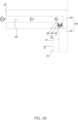
- FIG. 5A illustrates an enlarged example of part B of FIG. 4 .
- the speaker module 230 may include a diaphragm 233 that generates audio by vibrating, a voice coil 234 that provides vibration to the diaphragm 233, and a permanent magnet 235 capable of forming a magnetic field.
- the permanent magnet 235 may be located between the voice coils 234.
- the speaker module 230 may output audio by generating vibration of the diaphragm 233 when a current flows through the voice coil 234.
- the permanent magnet 235 may form a magnetic field
- the voice coil 234 may also form a magnetic field.
- the magnetic field by the permanent magnet 235 and the magnetic field by the voice coil 234 attract or repel each other, so that the voice coil 234 may move.
- the diaphragm 233 may vibrate to output audio.
- the speaker module 230 may have an arrangement structure for transmitting audio in a direction D1 in which the display area 211 of the display panel 210.
- the speaker module 230 may be disposed in the slit 250.
- the speaker module 230 may be disposed at an intermediate point or an end of the slit 250 extending from the front surface 224 of the second frame 223 to the inside of the second frame 223.
- the audio emission direction of the speaker module 230 may be adjusted through an arrangement structure of the diaphragm 233 and the slit 250.
- the speaker module 230 may be disposed such that a surface in which the diaphragm 233 faces within the slit 250 faces in the direction D1 in which the display area 211 faces.
- the speaker module 230 may be disposed in the slit 250 such that the diaphragm 233 faces the front surface 224 of the second frame 223.
- the speaker module 230 may transmit audio in a direction D1 in which the display area 211 of the display panel 210 faces through the slit 250 by vibration generated from the diaphragm 233.
- FIG. 5B illustrates another example of an enlarged part B of FIG. 4 .
- the speaker module 230 may be disposed to be connected to a part of the slit 250.
- the slit 250 may extend from the front surface 224 of the second frame 223 to the inner surface of the second frame 223.
- the speaker module 230 may be disposed such that a surface facing the diaphragm 233 is connected to the slit 250.
- the speaker module 230 may be disposed above or below the slit 250 such that the diaphragm 233 faces the slit 250.
- the audio emitted from the speaker module 230 may be transmitted in a direction D1 in which the display area 211 of the display panel 210 faces through the slit 250.
- the diaphragm 233 When a current is applied to the voice coil 234, the diaphragm 233 may vibrate. Since vibration by the diaphragm 233 is transmitted through the slit 250, the speaker module 230 may transmit audio to the outside of the diaphragm 223. Since the slit 250 is formed to face the front surface 224 of the second frame 223, audio emitted from the speaker module 230 may be transmitted in a direction D1 in which the display area 211 faces. The speaker module 230 may transmit audio in a direction D1 in which the display area 211 faces. The speaker module 230 may transmit audio to a user viewing visual information displayed on display area 211. According to an embodiment, the display device 200 may provide high-quality audio to the user by matching the direction of providing visual information and the direction of providing auditory information.
- FIG. 6 exemplarily illustrates components included in a second frame of a display device according to an embodiment.
- the second frame 223 of the display device 200 may accommodate the speaker module 230, the circuit board 240, and a sensor 280. According to an embodiment, since the speaker module 230, the circuit board 240, and the sensor 280 are disposed in the second frame 223, the speaker module 230, the circuit board 240, and the sensor 280 may easily maintain electrical connection with each other.
- the speaker module 230 may include a first speaker 231 and a second speaker 232.
- the first speaker 231 and the second speaker 232 may be spaced apart from each other in the second frame 223.
- the first speaker 231 may output a first audio signal
- the second speaker 232 may output a second audio signal distinguished from the first audio signal.
- the first speaker 231 may be disposed at the left side in the second frame 223, output a middle-pitched audio signal and high-pitched audio signal (e.g., 1000 Hz or more), and the second speaker 232 may be disposed at the right side in the second frame 223 and output a low-pitched audio (e.g., 20 Hz to 500 Hz).
- the speaker module 230 may output a stereophonic sound through the first speaker 231 and the second speaker 232.
- the first speaker 231 and the second speaker 232 are symmetrically disposed at both sides inside the second frame 223, thereby providing a stereophonic sound to a user.
- the circuit board 240 may include a main board 241 operatively connected to the display panel 210, and a power board 242 for supplying power to the main board 241 and the display panel 210.
- the main board 241 may process an image signal for providing an image signal to the display panel 210, and process an audio signal for providing an audio signal to the speaker module 230.
- the main board 241 may convert an image signal received from the outside into an image signal that may be provided as visual information through the display panel 210, and may transmit the converted image signal to the display driver integrated circuit (e.g., the display driver integrated circuit 270 of FIG. 4 ).
- the main board 241 may convert a digital signal received from the outside into an analog signal that may be provided as audio information through the speaker module 230.
- the power board 242 may supply power to the main board 241 and the display panel 210.
- the power board 242 may include power supply circuit elements for supplying power required for driving the display device 200.
- the power board 242 may include a power connector for inputting external power, and the power connector may be exposed to the outside of the display device 200.
- the sensor 280 may detect an external object, receive a control command from the external object, or identify an operation of the external object.
- the sensor 280 may be electrically connected to the main board 241.
- the sensor 280 may identify the user's operation, and the main board 241 may perform a designated function based on the user's operation identified through the sensor 280.
- the main board 241 may perform functions such as turn-on/turn-off, enlargement and reduction of the display area 211, volume adjustment, and channel change.
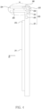
- FIG. 7 is a front view of a second frame of a display device according to an embodiment.
- the second frame 223 may include a slit 250 on the front surface 224 of the second frame 223 facing the direction D1 in which the second frame 223 extends.
- the slit 250 may extend from the front surface 224 of the second frame 223 toward the inside.
- the second frame 223 may include the upper plate 225 and the lower plate 226 disposed on the lower part of the upper plate 225 and spaced apart from the upper plate 225, and may include a slit 250 formed by separation between the upper plate 225 and the lower plate 226.
- the thickness of the display device may be increased.
- the display device 200 may have a thin thickness since the display panel 210 and the circuit board 240 are disposed on different planes.
- the slit 250 may have a thickness sufficient to transmit the vibration of the audio emitted from the speaker module 230.
- a thickness T1 of the second frame 223 may be about 15 mm to about 20 mm
- a thickness T2 of the slit 250 may be about 2 mm to about 6 mm.
- the display panel 210 may be about 10 mm or less.
- the first frame e.g., the first frame 221 of FIG.
- a thickness of the first frame 221 in which the display panel 210 is disposed may be thin.
- the speaker module 230 of the display device 200 may include a first speaker 231 and a second speaker 232 spaced apart from the first speaker 231.
- the first speaker 231 may be disposed on the left side with respect to the center of the second frame 223, and the second speaker 232 may be disposed on the right side with respect to the center of the second frame 223.
- the first speaker 231 and the second speaker 232 may output different audio signals.
- the first speaker 231 may output a first audio signal
- the second speaker 232 may output a second audio signal distinguished from the first audio signal, thereby providing stereophonic sound to a user. Audio emitted from the first speaker 231 and the second speaker 232 may be transmitted to the user through the slit 250.
- the user may be provided three-dimensional sound through the first speaker 231 and the second speaker 232 that output different audio signals at different locations.
- the sensor 280 may include at least one of a proximity sensor, an infrared sensor 281, a camera 282, and an ultrasonic sensor.
- the display device 200 may include the infrared sensor 281 and the camera 282, and the infrared sensor 281 and the camera 282 may be disposed in the second frame 223.
- the infrared sensor 281 and the camera 282 may be disposed in the slit 250 and may be exposed to the outside through the slit 250.
- the sensor 280 may detect light or sound waves from the outside of the display device 200 through the slit 250.
- the infrared sensor 281 may receive infrared rays emitted from an external electronic device (e.g., a remote control) through the slit 250.
- camera 282 may identify a user's operation through slit 250, and display device 200 may perform a function related to a signal related to the identified operation.
- the ultrasonic sensor may identify a user's location by emitting a sound wave pulse through the slit 250, measuring a reflected sound wave, and detecting a transmission/reception time interval of the sound wave.
- the display device 200 may adjust the volume of the speaker module 230 or provide a notification based on the location of the user identified through the ultrasonic sensor. For example, when the distance of the user from the display panel 210 is located closer than the threshold value, the display device 200 may provide a warning notification and reduce the volume of the speaker module 230.
- FIG. 8 illustrates a second state of a display device according to an embodiment.
- the second state of the display device 200 may mean a state in which the second frame 223 is positioned below the first frame 221.
- the second state may be distinguished from the first state described above.
- the display device 200 when the display device 200 is in the second state, the display device 200 according to an embodiment may be used as the stand-type display device 200 in which the second frame 223 is disposed on the ground or the table T.
- the display device 200 may change the posture of the housing 220 according to a situation. According to an embodiment, the display device 200 may be changed from the first state to the second state, and may be changed from the second state to the first state.
- the display device 200 may enable appropriate arrangement according to a situation by allowing the posture of change of the housing 220. According to an embodiment, the display device 200 may change the posture of the first state or the second state according to a user's preference and a structure of an indoor space in which the display device 200 is disposed.
- the display device 200 when placed in a narrow indoor space, the display device 200 may be installed on the wall in a first state to secure an indoor space, and when moved to a large indoor space, the display device 200 may be disposed on the ground or on the table T in a second state.
- the second frame 223 of the display device 200 may extend in a direction D1 in which the display panel 210 faces.
- the second frame 223 may support the display device 200 on the ground or on the table T. Since the second frame 223 extends in the direction D1 in which the display area 211 of the display panel 210 faces, the audio emitted from the speaker module 230 disposed in the second frame 223 may be transmitted in a direction D1 in which the display panel 210 faces.
- FIG. 9 illustrates a second state of the display device and a support according to an embodiment.
- the display device 200 may include a support 260 supporting the housing 220.
- the support 260 in the second state of the housing 220, may include a first body 261 attached to the first frame 221 and a second body 262 that is bent from the first body 261 in a direction D2 opposite to the extending direction D1 of the second frame 223 and supports the housing 220.
- the second body 262 may be fixed to the housing 220.
- the second body 262 may locate the display device 200 on the ground or on a table by supporting the housing 220 on the surface facing the surface on which the display panel (e.g., the display panel 210 of FIG. 8 ) of the housing 220 is disposed.
- the display device 200 in the second state, may be disposed on an external object.
- the second frame 223 of the housing 220 may be located below the first frame 221 and may be in contact with an external object.
- the first body 261 of the support 260 may be attached to a surface facing the surface on which the display panel 210 of the housing 220 is disposed and the second body 262 may be in contact with the ground or table T in a direction D2 opposite to the direction D1 facing the second frame 223.
- the first body 261 may be attached to the housing 220 through an adhesive member, and the second body 262 may be attached to the ground or the table T through the adhesive member.
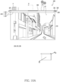
- FIGS. 10A to 10C illustrate a process of changing visual information according to a posture of a display device, according to an embodiment.
- the display device 200 may include a posture detection sensor 283 for changing displayed visual information and one or more processor (e.g., the one or more processors 120 of FIG. 1 ).
- the posture detection sensor 283 may be disposed in the first frame 221 or the second frame 223.
- the one or more processors 120 may identify the posture of the housing 220 through the posture detection sensor 283.
- the posture detection sensor 283 may be a gyro sensor capable of transmitting a signal related to angular velocity to the one or more processors 120 by measuring the Coriolis force.
- the posture detection sensor 283 may be a gravity sensor capable of transmitting a signal related to the posture of the housing 220 to the one or more processors 120 by measuring the direction of gravity applied to the display device 200.
- the one or more processors 120 may be disposed in the second frame 223.
- the one or more processors 120 may identify the posture change of the housing 220 based on the detection result of the posture detection sensor 283, and may change visual information provided through the display area 211 in response to the identification. For example, when the posture change is identified through the posture detection sensor 283, the one or more processors 120 may transmit a signal requesting conversion of visual information to the display drier integrated circuit (e.g., the display drier integrated circuit 270 of FIG. 4 ).
- the display drier integrated circuit e.g., the display drier integrated circuit 270 of FIG. 4
- the one or more processors 120 may identify that the posture of the housing 220 is not changed, and may not generate a signal for controlling the conversion of visual information provided through the display area 211.
- the one or more processors 120 may identify that the posture of the housing 220 is changed and generate a signal for controlling the conversion of visual information provided through the display area 211.
- the one or more processors 120 may transmit a signal for controlling the conversion of the visual information to the display drier integrated circuit 270.
- FIG 10A illustrates a display device 200 in which first visual information is displayed in a first state of the housing 220.
- the display device 200 may be installed on an external object such as a wall, a ceiling, or a pillar.
- the one or more processors 120 may provide first visual information through the display area 211 in the first state.
- the first visual information may mean visual information capable of providing a natural image through the display area 211 in the first state of the housing 220.
- the first visual information may be content provided through a display area.
- An upper area of the content of the first visual information may be disposed at one periphery where the second frame 223 of the display panel 210 is located.
- the speaker module 230 may include a first speaker 231 outputting a first audio signal and a second speaker 232 outputting a second audio signal.
- the first speaker 231 may provide audio to the user from the left side with respect to the display panel 210
- the second speaker 232 may provide audio to the user from the right side with respect to the display panel 210.
- FIG. 10B illustrates a display device 200 in which first visual information is displayed immediately after the housing 220 is changed from the first state to the second state.
- the first visual information provided through the display area 211 may be awkward.
- the user changes the display device 200 to the second state by rotating the display device 200 180 degrees in the first state the first visual information provided through the display area 211 may be displayed in an inverted state.
- FIG. 10C illustrates a display device 200 in which second visual information is displayed in a second state of the housing 220.
- the display device 200 may be disposed on the ground or a table.
- the posture detection sensor 283 may detect an angular velocity by measuring the Coriolis force.
- the one or more processors 120 may identify the change from the first state to the second state.
- the one or more processors 120 may provide second visual information through the display area 211.
- the one or more processors 120 may change the first visual information into second visual information, in response to identifying the change from the first state to the second state of the housing 220 through the posture detection sensor 283.
- the second visual information may be substantially the same information as the first visual information.
- the second visual information may mean visual information capable of providing a natural image through the display area 211 in the second state of the housing 220.
- the second visual information may be an image obtained by inverting the first visual information right and left and top and bottom.
- the second visual information may be content provided through the display area.
- a lower area of the content of the second visual information may be disposed at one periphery where the second frame 223 of the display panel 210 is located.
- the one or more processors 120 may provide an animation.
- the one or more processors 120 may provide an animation in which the display area 211 rotates 180 degrees.
- the one or more processors 120 may change audio signals output from the first speaker 231 and the second speaker 232.
- the one or more processors 120 may change the audio signal output through the first speaker 231 from the first audio signal to the second audio signal, and may change the audio signal output through the second speaker 232 from the second audio signal to the first audio signal.
- the first speaker 231 may provide audio to the user from the right side with respect to the display panel 210
- the second speaker 232 may provide audio to the user from the left side with respect to the display panel 210.
- the display device 200 may allow free arrangement. According to an embodiment, the display device 200 may change the posture of the housing 220 from the first state to the second state or from the second state to the first state. When the posture of the housing 220 is changed, a natural image may be provided to the user through the posture detection sensor 283 and the one or more processors 120. According to an embodiment, the one or more processors 120 may identify the change of posture of the housing 220 through the posture detection sensor 283, and may change visual information provided through the display area 211 of the display panel 210 in response to the identification.
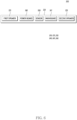
- FIG. 11 illustrates an example of an operation of a display device that changes visual information according to a posture of a housing, according to an embodiment. This operation may be performed by the display device (e.g., the display device 200 of FIG. 2 ) illustrated in FIG. 2 .
- the display device e.g., the display device 200 of FIG. 2
- FIG. 2 illustrates an example of an operation of a display device that changes visual information according to a posture of a housing, according to an embodiment. This operation may be performed by the display device (e.g., the display device 200 of FIG. 2 ) illustrated in FIG. 2 .
- the one or more processors may identify the first state of the housing (e.g., the housing 220 of FIG. 10A ) through the posture detection sensor(e.g., the posture detection sensor 283 of FIG. 10A ).
- the first state may be identified by measuring the direction of gravity applied to the display device 200.
- the first state may be identified, through the fact that there is no change in the posture of the housing 220 from the final posture of the housing 220.
- the one or more processors may provide the first visual information through a display area (e.g., the display area 211 of FIG. 10A ) of the display panel (e.g., the display panel 210 of FIG. 10A ), based on the first state of the housing 220 identified through the posture detection sensor 283.
- the display area 211 of display panel 210 may provide first visual information to a user.
- the first visual information may mean visual information capable of providing a natural image through the display area 211 in the first state of the housing 220.
- the first visual information may be content provided through a display area.
- An upper area of the content of the first visual information may be disposed at one periphery where the second frame 223 of the display panel 210 is located.
- the one or more processors 120 may identify that the posture of the housing 220 is switched from the first state to the second state through the posture detection sensor 283. For example, when the posture of the housing 220 is changed, the posture detection sensor 283 may measure the angular velocity by measuring the Coriolis force. For another example, the one or more processors 120 may identify the posture change of housing 220 by identifying the direction of gravity applied to housing 220 through posture detection sensor 283. According to an embodiment, when the value measured by the posture detection sensor 283 is less than the threshold value, the one or more processors 120 may identify that the posture of the housing 220 is not changed. When it is identified that the posture of the housing 220 is not changed, the one or more processors 120 may provide the first visual information through the display area 211.
- the one or more processors 120 may identify that the posture of the housing 220 is changed from the first state to the second state. For example, when the angular velocity value measured by the posture detection sensor 283 is greater than or equal to the threshold value, or the change value in the direction of the measured gravity is greater than or equal to the threshold value, the one or more processors 120 may identify the change of posture of housing 220.
- the one or more processors 120 may provide the second visual information through the display area 211 of the display panel 210 based on the second state of the housing 220 identified through the posture detection sensor 283.
- the display area 211 of display panel 210 may provide second visual information to a user.
- the second visual information may mean visual information capable of providing a natural image through the display area 211.
- the second visual information may be an image obtained by inverting the first visual information right and left and top and bottom.
- the second visual information may be content provided through a display area.
- a lower area of the content of the second visual information may be disposed at one periphery where the second frame 223 of the display panel 210 is located.
- the display device 200 may identify the posture change of the housing 220 and change visual information provided through the display area 211 of the display panel 210 based on the posture of the housing 220.
- the user may freely switch the arrangement state of the display device 200 and may be provided natural visual information according to the change of the arrangement state.
- the first state and the second state may be mutually changed.
- the display device 200 may perform the same operation when switching from the second state of the housing 220 to the first state.
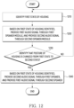
- FIG. 12 illustrates an example of an operation of a display device that changes an audio signal according to a posture of a housing, according to an embodiment. This operation may be performed by the display device (e.g., the display device 200 of FIG. 2 ) illustrated in FIG. 2 .
- the display device e.g., the display device 200 of FIG. 2
- FIG. 2 illustrates an example of an operation of a display device that changes an audio signal according to a posture of a housing, according to an embodiment. This operation may be performed by the display device (e.g., the display device 200 of FIG. 2 ) illustrated in FIG. 2 .
- the speaker module may include a first speaker (e.g., a first speaker 231 of FIG. 6 ) and a second speaker (e.g., a second speaker 232 of FIG. 6 ) spaced apart from each other in a second frame (e.g., the second frame 223 of FIG. 2 ) and outputting different audio signals.
- the speaker module 230 may provide stereophonic sound to a user using the display device 200 through the first speaker 231 and the second speaker 232.
- the one or more processors e.g., the one or more processors 120 of FIG.
- the speaker module 230 may output different sounds according to the sound range band of the audio signal.
- the one or more processors 120 may control to provide a high-pitched audio signal and a middle-pitched sound (e.g., 1000 Hz or higher) through the first speaker 231 and control to provide a low-pitched audio (e.g., 20 Hz to 500 Hz) through the second speaker 232.
- the user may be provided stereophonic and rich sound through the first speaker 231 and the second speaker 232 that emit audio of different frequencies.
- the audio emitted through the speaker module 230 may be changed left and right.
- the first speaker 231 may be disposed on the left side respect to the display panel 210
- the second speaker 232 may be disposed on the right side respect to the display panel 210.
- the arrangement structure of the first speaker 231 and the second speaker 232 may be changed.
- the first speaker 231 When the posture of the housing 220 is changed, the first speaker 231 may be disposed on the right side with respect to the display panel 210, and the second speaker 232 may be disposed on the left side with respect to the display panel 210. Since the arrangement structure of the first speaker 231 and the second speaker 232 is changed by the posture change of the housing 220, the quality of sound provided to the user may be distorted.
- the one or more processors 120 may control an audio signal output through the first speaker 231 and the second speaker 232 based on the posture of the housing 220.
- the one or more processors 120 may control the audio channel allocated to the first speaker 231 and the second speaker 232 to provide substantially the same audio through the speaker module 230 regardless of the switching.
- the posture detection sensor may identify the first state of the housing 220.
- the first state may be identified, through the fact that there is no change in the posture of the housing 220 from the final posture of the housing 220.
- the one or more processors 120 may provide an audio signal through the speaker module 230 based on the first state of the housing 220 identified through the posture detection sensor 283. For example, in the first state of the housing 220 illustrated in FIG. 10A , the one or more processors 120 may provide a first audio signal through the first speaker 231 and a second audio signal through the second speaker 232.
- the one or more processors 120 may identify that the posture of the housing 220 is changed from the first state to the second state through the posture detection sensor 283.
- the posture detection sensor 283 may measure the angular velocity by measuring the Coriolis force when the posture of the housing 220 is changed.
- the one or more processors 120 may identify that the posture of the housing 220 is not changed.
- the one or more processors 120 may identify that the posture of the housing 220 is changed from the first state to the second state.
- the one or more processors 120 may identify that the posture of the housing 220 is not changed, and may continue to provide a first audio signal through the first speaker 231 and a second audio signal through the second speaker 232.
- the one or more processors 120 may provide an audio signal through the speaker module 230 based on the second state of the housing 220 identified through the posture detection sensor 283. According to an embodiment, when the posture of the housing 220 changes from the first state to the second state, the one or more processors 120 may change audio signals output from the first speaker 231 and the second speaker 232. For example, in the second state of the housing 220 illustrated in FIG. 10C , the one or more processors 120 may provide a second audio signal through the first speaker 231 and a first audio signal through the second speaker 232. According to an embodiment, the display device 200 may provide substantially the same audio signal to the user regardless of the posture change of the housing 220.
- the display device 200 may identify the posture change of the housing 220 and may convert an audio signal provided through the speaker module 230 based on the posture change of the housing 220.
- the user may freely change the arrangement state of the display device 200 and may be provided substantially the same sound regardless of the change of the arrangement state.
- the first state and the second state may be mutually changed.
- the display device 200 may perform the same operation when switching from the second state of the housing 220 to the first state.
- a display device(e.g., display device 200 of FIG. 2 ) may comprise a display panel(e.g., display panel 210 of FIG. 2 ); a housing(e.g., housing 220 of FIG. 2 ) comprising a first frame(e.g., first frame 221 of FIG. 2 ) comprising a plate supporting one surface of the display panel and a second frame(e.g., second frame 223 of FIG. 2 ) integrally formed with the first frame, and extending from one periphery(e.g., one periphery 222 of FIG. 2 ) of the first frame in a direction toward which the display area(e.g., display area 211 of FIG.
- the second frame may comprise a slit (e.g., slit 250 of FIG. 2 ) disposed on an outer surface of the second frame facing a direction in which the second frame extends to transmit audio emitted from the speaker module in a direction toward which the display area faces.
- a slit e.g., slit 250 of FIG. 2
- the display device may further comprise a display driver integrated circuitry (DDI)(e.g., the display drier integrated circuit 270 of FIG. 4 ) disposed closer to the one periphery among peripheries of the first frame than another periphery on which the second frame is formed and operatively connected to the circuit board.
- DCI display driver integrated circuitry
- the slit may extend from a surface facing a diaphragm(e.g., diaphragm 233 of FIG. 5A ) of the speaker module to the outer surface of the second frame.
- the diaphragm of the speaker module may be disposed in a direction in which the display area of the display panel faces.
- the circuit board may further comprise a main board(e.g., main board 241 of FIG. 6 ) operatively connected to the display panel; and a power board(e.g., power board 242 of FIG. 6 ) in the second frame supplying power to the main board and the display panel.
- a main board e.g., main board 241 of FIG. 6
- a power board e.g., power board 242 of FIG. 6
- the speaker module may comprise a first speaker (e.g., first speaker 231 of FIG. 6 ) outputting a first audio signal and a second speaker (e.g., second speaker 232 of FIG. 6 ) spaced apart from the first speaker within the second frame and outputting a second audio signal.
- a first speaker e.g., first speaker 231 of FIG. 6
- a second speaker e.g., second speaker 232 of FIG. 6
- the display device may further comprise a sensor (e.g., the sensor 280 in FIG. 6 ) disposed within the second frame, and wherein the sensor may comprise an infrared sensor or a camera.
- a sensor e.g., the sensor 280 in FIG. 6
- the sensor may comprise an infrared sensor or a camera.
- the senor may be exposed to the outside of the display device through the slit and may detect light or sound waves from the outside of the display device through the slit.
- a thickness of the second frame(e.g., thickness T1 in FIG. 7 ) may be 15mm to 2mm and a thickness(e.g., thickness T2 of FIG. 7 ) of the slit may be 2mm to 5mm.
- the extending direction of the second frame may be perpendicular to the first frame.
- a display device may comprise a display panel; a housing comprising a first frame comprising a plate supporting one surface of the display panel and a second frame integrally formed with the first frame, and extending from one periphery of the first frame in a direction toward which the display area of the display panel faces; a speaker module disposed in the second frame; a posture detection sensor(e.g., posture detection sensor 283 of FIG. 10A ) within the housing that identifies a posture of the housing; and one or more processors(e.g., one or more processors 120 of FIG. 1 ) within the second frame that changes visual information provided through the display area based on a signal obtained from the posture detection sensor.
- a posture detection sensor e.g., posture detection sensor 283 of FIG. 10A
- processors e.g., one or more processors 120 of FIG. 1
- the posture of the housing may be changeable to a first state in which the second frame is positioned above the first frame or a second state in which the second frame is positioned below the first frame.
- the one or more processors may be configured to provide first visual information through the display area in the first state; identify that the housing is changed from the first state to the second state through the posture detection sensor; and change the first visual information to the second visual information to provide substantially same information as the first visual information through the display area, in response to the identification, according to a change in the posture of the housing.
- the display device may further comprise a support(e.g., support 260 of FIG. 3 ) comprising a first body(e.g., first body 261 of FIG. 3 ) attached to the first frame and fixed to an external object and a second body (e.g., second body 262 of FIG. 3 ) extending from the first body along the second frame, when the housing is in the first state.
- a support e.g., support 260 of FIG. 3
- a first body e.g., first body 261 of FIG. 3
- second body e.g., second body 262 of FIG. 3
- the display device may further comprise a support (e.g., support 260 of FIG. 9 ) comprising a first body (e.g., first body 261 of FIG. 9 ) attached to the first frame and a second body (e.g., second body 262 of FIG. 9 ) bent from the first body in a direction opposite to extending direction of the second frame and supporting the housing.
- a support e.g., support 260 of FIG. 9
- a first body e.g., first body 261 of FIG. 9
- second body e.g., second body 262 of FIG. 9
- the speaker module may comprise a first speaker and a second speaker spaced apart from the first speaker within the second frame, wherein the one or more processors may be configured to provide a first audio signal through the first speaker and a second audio signal through the second speaker in the first state; identify that the housing is changed from the first state to the second state through the posture detection sensor; and provide the second audio signal through the first speaker and provide the first audio signal through the second speaker, in response to the identification, according to a change in the posture of the housing.
- the second frame may comprise a slit disposed on an outer surface of the second frame toward the extending direction of the second frame to transmit the audio emitted from the speaker module in a direction toward which the display area faces.
- the slit may extend from a surface facing a diaphragm of the speaker module to the outer surface of the second frame.
- the display device may further comprise a circuit board disposed in the second frame and operatively connected to the display panel and the speaker module; and a display driver integrated circuitry (DDI) disposed closer to the one periphery among peripheries of the first frame than another periphery on which the second frame is formed and operatively connected to the circuit board.
- DCI display driver integrated circuitry
- the display device may further comprise a sensor disposed within the second frame, wherein the sensor may comprise infrared a sensor or a camera.
- each of such phrases as “A or B,” “at least one of A and B,” “at least one of A or B,” “A, B, or C,” “at least one of A, B, and C,” and “at least one of A, B, or C,” may include any one of, or all possible combinations of the items enumerated together in a corresponding one of the phrases.
- such terms as “1st” and “2nd,” or “first” and “second” may be used to simply distinguish a corresponding component from another, and does not limit the components in other aspect (e.g., importance or order).
- an element e.g., a first element
- the element may be coupled with the other element directly (e.g., wiredly), wirelessly, or via a third element.
- module may include a unit implemented in hardware, software, or firmware, and may interchangeably be used with other terms, for example, “logic,” “logic block,” “part,” or “circuitry”.
- a module may be a single integral component, or a minimum unit or part thereof, adapted to perform one or more functions.
- the module may be implemented in a form of an application-specific integrated circuit (ASIC).
- ASIC application-specific integrated circuit
- Various embodiments as set forth herein may be implemented as software (e.g., program) including one or more instructions that are stored in a storage medium (e.g., internal memory or external memory) that is readable by a machine (e.g., display device).
- a processor of the machine e.g., display device
- the one or more instructions may include a code generated by a complier or a code executable by an interpreter.
- the machine-readable storage medium may be provided in the form of a non-transitory storage medium.
- non-transitory simply means that the storage medium is a tangible device, and does not include a signal (e.g., electromagnetic wave), but this term does not differentiate between where data is semipermanently stored in the storage medium and where the data is temporarily stored in the storage medium.
- a signal e.g., electromagnetic wave
- a method may be included and provided in a computer program product.
- the computer program product may be traded as a product between a seller and a buyer.
- the computer program product may be distributed in the form of a machine-readable storage medium (e.g., compact disc read only memory (CD-ROM)), or be distributed (e.g., downloaded or uploaded) online via an application store (e.g., PlayStore TM ), or between two user devices (e.g., smart phones) directly. If distributed online, at least part of the computer program product may be temporarily generated or at least temporarily stored in the machine-readable storage medium, such as memory of the manufacturer's server, a server of the application store, or a relay server.
- CD-ROM compact disc read only memory
- an application store e.g., PlayStore TM
- two user devices e.g., smart phones
- each component e.g., a module or a program of the above-described components may include a single entity or multiple entities, and some of the multiple entities may be separately disposed in different components. According to various embodiments, one or more of the above-described components may be omitted, or one or more other components may be added. Alternatively or additionally, a plurality of components (e.g., modules or programs) may be integrated into a single component. In such a case, according to various embodiments, the integrated component may still perform one or more functions of each of the plurality of components in the same or similar manner as they are performed by a corresponding one of the plurality of components before the integration.
- operations performed by the module, the program, or another component may be carried out sequentially, in parallel, repeatedly, or heuristically, or one or more of the operations may be executed in a different order or omitted, or one or more other operations may be added.
Landscapes
- Engineering & Computer Science (AREA)
- Signal Processing (AREA)
- Physics & Mathematics (AREA)
- Acoustics & Sound (AREA)
- Health & Medical Sciences (AREA)
- Otolaryngology (AREA)
- Multimedia (AREA)
- Devices For Indicating Variable Information By Combining Individual Elements (AREA)
Applications Claiming Priority (2)
| Application Number | Priority Date | Filing Date | Title |
|---|---|---|---|
| KR1020210169047A KR20230081204A (ko) | 2021-11-30 | 2021-11-30 | 오디오의 전면 방사를 위한 디스플레이 장치 |
| PCT/KR2022/013582 WO2023101158A1 (ko) | 2021-11-30 | 2022-09-08 | 오디오의 전면 방사를 위한 디스플레이 장치 |
Publications (2)
| Publication Number | Publication Date |
|---|---|
| EP4401422A1 true EP4401422A1 (de) | 2024-07-17 |
| EP4401422A4 EP4401422A4 (de) | 2025-01-08 |
Family
ID=86499646
Family Applications (1)
| Application Number | Title | Priority Date | Filing Date |
|---|---|---|---|
| EP22901518.5A Pending EP4401422A4 (de) | 2021-11-30 | 2022-09-08 | Anzeigevorrichtung für die frontabstrahlung von audio |
Country Status (3)
| Country | Link |
|---|---|
| US (1) | US12368992B2 (de) |
| EP (1) | EP4401422A4 (de) |
| CN (1) | CN118120259A (de) |
Families Citing this family (1)
| Publication number | Priority date | Publication date | Assignee | Title |
|---|---|---|---|---|
| WO2023282374A1 (ko) * | 2021-07-09 | 2023-01-12 | 엘지전자 주식회사 | 디스플레이 디바이스 |
Family Cites Families (31)
| Publication number | Priority date | Publication date | Assignee | Title |
|---|---|---|---|---|
| JP3411784B2 (ja) | 1997-05-09 | 2003-06-03 | カネボウ株式会社 | ディスプレイ |
| JP5010810B2 (ja) * | 2005-05-13 | 2012-08-29 | 三洋電機株式会社 | 電子機器 |
| JP4528672B2 (ja) * | 2005-06-09 | 2010-08-18 | 株式会社東芝 | 映像表示装置 |
| KR20080063681A (ko) | 2007-01-02 | 2008-07-07 | 엘지전자 주식회사 | 디스플레이 장치 |
| JP5034756B2 (ja) | 2007-08-06 | 2012-09-26 | ソニー株式会社 | アンテナ及びテレビジョン受像機 |
| KR20110055337A (ko) | 2009-11-18 | 2011-05-25 | 삼성전자주식회사 | 디스플레이장치 |
| KR101725540B1 (ko) | 2009-11-26 | 2017-04-11 | 엘지디스플레이 주식회사 | 액정표시장치 |
| KR101631275B1 (ko) | 2010-02-02 | 2016-06-16 | 삼성전자주식회사 | 스탠드-벽걸이 전환이 가능한 사운드 플레이트를 채용한 전자 기기 |
| KR101843337B1 (ko) | 2010-10-28 | 2018-03-30 | 삼성전자주식회사 | 디스플레이 모듈 및 디스플레이 시스템 |
| KR101903398B1 (ko) | 2012-04-16 | 2018-10-02 | 엘지디스플레이 주식회사 | 디스플레이 장치 |
| US20140044300A1 (en) * | 2012-08-08 | 2014-02-13 | Kabushiki Kaisha Toshiba | Electronic apparatus, sound quality improvement method, and sound quality improvement member |
| KR20140121525A (ko) | 2013-04-05 | 2014-10-16 | 삼성전자주식회사 | 디스플레이 장치 |
| WO2015060678A1 (en) * | 2013-10-24 | 2015-04-30 | Samsung Electronics Co., Ltd. | Method and apparatus for outputting sound through speaker |
| KR102349453B1 (ko) * | 2015-07-24 | 2022-01-10 | 삼성전자주식회사 | 스피커 장치 및 이를 포함하는 전자 장치 |
| KR102395490B1 (ko) | 2015-07-31 | 2022-05-09 | 엘지전자 주식회사 | 디스플레이 장치 |
| KR102463639B1 (ko) | 2015-08-28 | 2022-11-07 | 엘지전자 주식회사 | 디스플레이 장치 |
| KR20180095750A (ko) | 2017-02-17 | 2018-08-28 | 희성전자 주식회사 | 스탠드 일체형 디스플레이 장치 |
| CN207166638U (zh) * | 2017-08-11 | 2018-03-30 | 湖州世泰酒店设计策划顾问有限公司 | 一种画框式电视机 |
| KR20190021523A (ko) | 2017-08-22 | 2019-03-06 | 희성전자 주식회사 | 디스플레이 장치용 백 커버 및 이를 구비하는 디스플레이 장치 |
| KR102456054B1 (ko) * | 2017-12-11 | 2022-10-17 | 엘지디스플레이 주식회사 | 액정표시장치 |
| KR102637264B1 (ko) | 2018-01-25 | 2024-02-19 | 엘지전자 주식회사 | 디스플레이 디바이스 |
| KR102557576B1 (ko) | 2018-04-23 | 2023-07-24 | 엘지전자 주식회사 | 디스플레이 디바이스 |
| KR102581285B1 (ko) * | 2019-01-03 | 2023-09-22 | 삼성전자주식회사 | 전자장치 |
| WO2020213375A1 (ja) * | 2019-04-16 | 2020-10-22 | ソニー株式会社 | 表示装置、制御方法、およびプログラム |
| CN110113453B (zh) * | 2019-04-24 | 2021-04-06 | 维沃移动通信有限公司 | 一种移动终端 |
| JP7552590B2 (ja) | 2019-05-09 | 2024-09-18 | ソニーグループ株式会社 | スピーカ装置、スピーカ、及び構造体 |
| KR102794749B1 (ko) * | 2019-12-31 | 2025-04-14 | 삼성전자주식회사 | 디스플레이 장치 및 디스플레이 장치의 음향 출력 방법 |
| CN111580771B (zh) | 2020-04-10 | 2021-06-22 | 三星电子株式会社 | 显示装置及该显示装置的控制方法 |
| KR102312879B1 (ko) * | 2020-04-10 | 2021-10-15 | 삼성전자주식회사 | 디스플레이 장치 및 그의 제어 방법 |
| US20240015426A1 (en) * | 2020-12-21 | 2024-01-11 | Sony Group Corporation | Display Device |
| US12262172B2 (en) * | 2022-05-19 | 2025-03-25 | Roku, Inc. | Compression loaded slit shaped waveguide |
-
2022
- 2022-09-08 EP EP22901518.5A patent/EP4401422A4/de active Pending
- 2022-09-08 CN CN202280070164.4A patent/CN118120259A/zh active Pending
- 2022-09-20 US US17/948,610 patent/US12368992B2/en active Active
Also Published As
| Publication number | Publication date |
|---|---|
| CN118120259A (zh) | 2024-05-31 |
| US20230171537A1 (en) | 2023-06-01 |
| EP4401422A4 (de) | 2025-01-08 |
| US12368992B2 (en) | 2025-07-22 |
Similar Documents
| Publication | Publication Date | Title |
|---|---|---|
| CN111580771B (zh) | 显示装置及该显示装置的控制方法 | |
| KR102874535B1 (ko) | 디스플레이 장치 | |
| KR20200072056A (ko) | 음향 모듈을 포함하는 전자 장치 | |
| KR102312879B1 (ko) | 디스플레이 장치 및 그의 제어 방법 | |
| US20030122777A1 (en) | Method and apparatus for configuring a computer system based on user distance | |
| EP3761666B1 (de) | Anzeigevorrichtung | |
| EP1271998A3 (de) | Lautsprechersystem, Mobilendgerät und elektronische Vorrichtung | |
| US20130004006A1 (en) | Display unit | |
| CN201878257U (zh) | 用于网络电视机的嵌入式无线天线 | |
| US20120106776A1 (en) | Slim Speaker | |
| KR20170069530A (ko) | 디스플레이 장치 | |
| EP4401422A1 (de) | Anzeigevorrichtung für die frontabstrahlung von audio | |
| JP2018534810A (ja) | 音再生ディスプレイ | |
| EP3908008B1 (de) | Anzeigevorrichtung und lautsprecher | |
| EP3312491B1 (de) | Einrichtung zur kopplung einer vielzahl von elektronischen vorrichtungen | |
| KR20230081204A (ko) | 오디오의 전면 방사를 위한 디스플레이 장치 | |
| KR102216064B1 (ko) | 복수의 전자 장치를 연결시키는 연결 장치 | |
| CN102104789A (zh) | 显示设备 | |
| US8325966B2 (en) | Detachable loudspeaker structure having both audio and supporting functions | |
| CN204578638U (zh) | 转动组件、支撑体、网络摄像头及智能设备 | |
| KR20130006902U (ko) | 전자 기기의 거치대 | |
| US11462199B2 (en) | Hybrid actuator and multimedia apparatus having the same | |
| JP2016225690A (ja) | 電子機器及び電子機器の制御方法 | |
| US11825256B2 (en) | Electronic apparatus emitting acoustic signal through display | |
| KR20150047411A (ko) | 틈 스피커를 통해 음향을 출력하는 방법 및 장치 |
Legal Events
| Date | Code | Title | Description |
|---|---|---|---|
| STAA | Information on the status of an ep patent application or granted ep patent |
Free format text: STATUS: THE INTERNATIONAL PUBLICATION HAS BEEN MADE |
|
| PUAI | Public reference made under article 153(3) epc to a published international application that has entered the european phase |
Free format text: ORIGINAL CODE: 0009012 |
|
| STAA | Information on the status of an ep patent application or granted ep patent |
Free format text: STATUS: REQUEST FOR EXAMINATION WAS MADE |
|
| 17P | Request for examination filed |
Effective date: 20240409 |
|
| AK | Designated contracting states |
Kind code of ref document: A1 Designated state(s): AL AT BE BG CH CY CZ DE DK EE ES FI FR GB GR HR HU IE IS IT LI LT LU LV MC MK MT NL NO PL PT RO RS SE SI SK SM TR |
|
| A4 | Supplementary search report drawn up and despatched |
Effective date: 20241211 |
|
| RIC1 | Information provided on ipc code assigned before grant |
Ipc: H04R 1/34 20060101ALI20241205BHEP Ipc: H04N 5/64 20060101ALI20241205BHEP Ipc: H04R 1/40 20060101ALI20241205BHEP Ipc: H04R 7/04 20060101ALI20241205BHEP Ipc: H04R 5/02 20060101AFI20241205BHEP |
|
| DAV | Request for validation of the european patent (deleted) | ||
| DAX | Request for extension of the european patent (deleted) |