EP4397449A1 - Betriebsendgerät, robotersystem und computerprogramm - Google Patents
Betriebsendgerät, robotersystem und computerprogramm Download PDFInfo
- Publication number
- EP4397449A1 EP4397449A1 EP22864566.9A EP22864566A EP4397449A1 EP 4397449 A1 EP4397449 A1 EP 4397449A1 EP 22864566 A EP22864566 A EP 22864566A EP 4397449 A1 EP4397449 A1 EP 4397449A1
- Authority
- EP
- European Patent Office
- Prior art keywords
- operation terminal
- robot
- control equipment
- equipment
- button
- Prior art date
- Legal status (The legal status is an assumption and is not a legal conclusion. Google has not performed a legal analysis and makes no representation as to the accuracy of the status listed.)
- Pending
Links
Images


Classifications
-
- B—PERFORMING OPERATIONS; TRANSPORTING
- B25—HAND TOOLS; PORTABLE POWER-DRIVEN TOOLS; MANIPULATORS
- B25J—MANIPULATORS; CHAMBERS PROVIDED WITH MANIPULATION DEVICES
- B25J13/00—Controls for manipulators
- B25J13/02—Hand grip control means
-
- B—PERFORMING OPERATIONS; TRANSPORTING
- B25—HAND TOOLS; PORTABLE POWER-DRIVEN TOOLS; MANIPULATORS
- B25J—MANIPULATORS; CHAMBERS PROVIDED WITH MANIPULATION DEVICES
- B25J13/00—Controls for manipulators
-
- B—PERFORMING OPERATIONS; TRANSPORTING
- B25—HAND TOOLS; PORTABLE POWER-DRIVEN TOOLS; MANIPULATORS
- B25J—MANIPULATORS; CHAMBERS PROVIDED WITH MANIPULATION DEVICES
- B25J13/00—Controls for manipulators
- B25J13/06—Control stands, e.g. consoles, switchboards
-
- B—PERFORMING OPERATIONS; TRANSPORTING
- B25—HAND TOOLS; PORTABLE POWER-DRIVEN TOOLS; MANIPULATORS
- B25J—MANIPULATORS; CHAMBERS PROVIDED WITH MANIPULATION DEVICES
- B25J19/00—Accessories fitted to manipulators, e.g. for monitoring, for viewing; Safety devices combined with or specially adapted for use in connection with manipulators
- B25J19/06—Safety devices
-
- B—PERFORMING OPERATIONS; TRANSPORTING
- B25—HAND TOOLS; PORTABLE POWER-DRIVEN TOOLS; MANIPULATORS
- B25J—MANIPULATORS; CHAMBERS PROVIDED WITH MANIPULATION DEVICES
- B25J5/00—Manipulators mounted on wheels or on carriages
-
- B—PERFORMING OPERATIONS; TRANSPORTING
- B25—HAND TOOLS; PORTABLE POWER-DRIVEN TOOLS; MANIPULATORS
- B25J—MANIPULATORS; CHAMBERS PROVIDED WITH MANIPULATION DEVICES
- B25J9/00—Program-controlled manipulators
- B25J9/16—Program controls
- B25J9/1656—Program controls characterised by programming, planning systems for manipulators
-
- B—PERFORMING OPERATIONS; TRANSPORTING
- B25—HAND TOOLS; PORTABLE POWER-DRIVEN TOOLS; MANIPULATORS
- B25J—MANIPULATORS; CHAMBERS PROVIDED WITH MANIPULATION DEVICES
- B25J9/00—Program-controlled manipulators
- B25J9/16—Program controls
- B25J9/1674—Program controls characterised by safety, monitoring, diagnostic
-
- G—PHYSICS
- G05—CONTROLLING; REGULATING
- G05B—CONTROL OR REGULATING SYSTEMS IN GENERAL; FUNCTIONAL ELEMENTS OF SUCH SYSTEMS; MONITORING OR TESTING ARRANGEMENTS FOR SUCH SYSTEMS OR ELEMENTS
- G05B19/00—Program-control systems
- G05B19/02—Program-control systems electric
- G05B19/18—Numerical control [NC], i.e. automatically operating machines, in particular machine tools, e.g. in a manufacturing environment, so as to execute positioning, movement or co-ordinated operations by means of program data in numerical form
- G05B19/409—Numerical control [NC], i.e. automatically operating machines, in particular machine tools, e.g. in a manufacturing environment, so as to execute positioning, movement or co-ordinated operations by means of program data in numerical form characterised by using manual data input [MDI] or by using control panel, e.g. controlling functions with the panel; characterised by control panel details or by setting parameters
-
- G—PHYSICS
- G05—CONTROLLING; REGULATING
- G05B—CONTROL OR REGULATING SYSTEMS IN GENERAL; FUNCTIONAL ELEMENTS OF SUCH SYSTEMS; MONITORING OR TESTING ARRANGEMENTS FOR SUCH SYSTEMS OR ELEMENTS
- G05B19/00—Program-control systems
- G05B19/02—Program-control systems electric
- G05B19/42—Recording and playback systems, i.e. in which the program is recorded from a cycle of operations, e.g. the cycle of operations being manually controlled, after which this record is played back on the same machine
Definitions
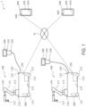
- a wireless communication network N is used in the present embodiment.
- the wireless communication network N may use a wireless LAN (Local Area Network) such as WiFi (Wireless Fidelity), a wireless WAN (Wide Area Network) utilizing a mobile communication network or the like, satellite communication, short-distance wireless communication such as Bluetooth (registered trademark) or ZigBee (registered trademark), or a combination of two or more of these.
- the mobile communication network may be one that uses, for example, a fourth-generation mobile communication system or a fifth-generation mobile communication system.
- the wireless communication network N is a wireless LAN.
- For the wired connection direct interconnection by cables or the like, a wired communication network, or a combination of these may be used.
- the wired communication network may be any type of network.
- the robot control equipment 200 controls actions of the robot 100 in accordance with commands received from the teaching equipment 300 and the operation terminal 400.
- the robot control equipment 200 controls the action of the servomotor 113 of each of the robotic arm 111 and the end effector 112 of the robot body 110 as well as the action of the servomotor 122 of the moving equipment 120.
- the robot control equipment 200 generates and outputs commands to cause the actions of the servomotors 113 and 122, and controls electric currents supplied to the servomotors 113 and 122.
- the robot control equipment 200 includes a computer and drive circuitry.
- the robot control equipment 200 can operate in two operation modes that are a teaching mode and a playback mode, and selectively executes one of the two operation modes.
- teaching may be performed by using the teaching equipment 300, the operation terminal 400, or both the teaching equipment 300 and the operation terminal 400.
- an operator may operate the teaching equipment 300 or the operation terminal 400, thereby causing the robot control equipment 200 to cause the robot 100 to perform an action, and action data obtained in the course of the action may be stored in the robot control equipment 200 as teaching data.
- teaching of the action may be performed.
- the teaching method may be any existing teaching method.
- the teaching equipment 300 is configured such that it is used for teaching to the robotic arm 111 and the end effector 112
- the operation terminal 400 is configured such that it is used for teaching to the moving equipment 120.
- the teaching equipment 300 may be configured such that it is used for teaching to the moving equipment 120
- the operation terminal 400 may be configured such that it is used for teaching to the robotic arm 111 and the end effector 112.
- the teaching equipment 300 receives an input made by an operator, and in accordance with the input content, outputs a command, information, data, etc. to the robot control equipment 200.
- the teaching equipment 300 is a teaching terminal that can be operated by the operator in a handheld manner, and the teaching equipment 300 is, for example, a teaching pendant.
- the teaching equipment 300 is a device that can perform teaching to the robot 100.
- the teaching equipment 300 may be a different apparatus including a computer, such as a personal computer.
- the teaching equipment 300 is an existing general-purpose teaching pendant.
- the teaching equipment 300 may be a teaching pendant that is designed and dedicated for the robot system 1.
- the teaching equipment 300 includes a display 310 and an inputter 320.
- the teaching equipment 300 when the teaching equipment 300 receives, via the inputter 320, a command to perform teaching or playback, the teaching equipment 300 outputs a command to perform teaching or playback to the robot control equipment 200.
- the teaching equipment 300 receives a manual operation performed by the operator, and outputs an operation command corresponding to the manual operation to the robot control equipment 200, thereby causing the robot 100 to perform an action in accordance with the manual operation.
- the teaching equipment 300 receives manual operations for the robotic arm 111 and the end effector 112.
- the teaching equipment 300 stores data of the performed action in the robot control equipment 200 as teaching data.
- the operation terminal 400 receives an input made by the operator, and in accordance with the input content, outputs a command, information, data, etc. to the robot control equipment 200.
- the operation terminal 400 includes a computer.
- the operation terminal 400 includes an inputter 410 and a presenter 420.
- the inputter 410 receives an input made by the operator, converts the input content into a signal, and outputs the signal to the computer of the operation terminal 400.
- the inputter 410 is, for example, a device that receives an input via an operation by the operator. Examples of such a device include a button, a lever, a dial, a joystick, a mouse, a key, a touch panel, and a motion capture device.
- the presenter 420 includes a structure that presents information or the like to the operator.
- the presenter 420 may include a structure that presents information or the like by outputting light, a sound, an image, tactile information such as a vibration and a load, a temperature, or a combination of two or more of these.
- the presenter 420 includes a display to output an image and a speaker to output a sound. Further, the display is a touch panel.
- the operation terminal 400 is a portable terminal that can be carried around by the operator.
- the operation terminal 400 include smart devices such as a smartphone, a smart watch, and a tablet.
- the operation terminal 400 may be a smart device developed and dedicated for the robot system 1.
- the operation terminal 400 is a general-purpose smart device that is available on the market.
- a computer program that realizes the functionality of the operation terminal 400 disclosed in the present specification and the claims may be incorporated in a general-purpose smart device, and as a result, the general-purpose smart device can function as the operation terminal 400.
- the computer program incorporated in the operation terminal 400 may be an application program.
- the application program is also referred to as a "robot operation application program".
- the robot operation application program may be a native application that is installed and runs on an OS (Operating System) that is system software of the operation terminal 400.
- the robot operation application program may be a web application that runs on a web browser to which the operation terminal 400 connects, or may be a hybrid application that runs on the operation terminal 400 and that utilizes a web environment for part of processing, such as for operations using data.
- the operation terminal 400 may be any device into which a computer program realizing the functionality of the operation terminal 400 disclosed in the present specification and the claims can be incorporated and which can receive an input of an operation that the operation terminal 400 is required to receive.
- the operation terminal 400 may be a combination of a personal computer and a display, a laptop personal computer, a combination of a game console and a display, or a PDA (Personal Digital Assistant).
- the operation terminal 400 is communicably connected to the robot control equipment 200.
- the operation terminal 400 is connected to the robot control equipment 200 via a communication path different from the teaching equipment 300.
- the operation terminal 400 may be communicably connected to the teaching equipment 300, and may be connected to the robot control equipment 200 via the teaching equipment 300.
- the operation terminal 400 is configured to operate the robot 100.
- the operation terminal 400 may be configured to operate only the robot body 110, only the moving equipment 120, or both the robot body 110 and the moving equipment 120.
- the operation terminal 400 may be configured to operate the robot 100 only in the teaching mode, only in the playback mode, or in both the teaching mode and the playback mode. In the present embodiment, in the teaching mode, the operation terminal 400 can operate the moving equipment 120, whereas in the playback mode, the operation terminal 400 can cause the entire robot 100 to play back a predetermined action that has been taught.
- the operation terminal 400 may be configured to be connected to the robot control equipment 200, alternatively with the teaching equipment 300, together with the teaching equipment 300 in parallel, or in series via the teaching equipment 300.
- These ways of connection indicate that these devices are in the state of being communicable with each other, such that commands, information, data, etc. can be transmitted and received to and from each other, and the connection is not limited to physical connection.
- the position of origin may include various states and positions of the robot 100.
- the position of origin may include: an initial position of the robot 100 for predetermined work that has been taught and the state of the robot 100 at the initial position; positions of the robot 100 set as a start point and a middle point in a process of the work and the state of the robot 100 at each position; positions of the robot 100 set as a start point and a middle point of a work section included in the process and the state of the robot 100 at each position; the position of the robot 100 at the end of the work and the state of the robot 100 at the position; the state of the robot 100 with the robotic arm 111 folded and accommodated within an area occupied by the moving equipment 120; the state of the robot 100 for preventing a person from getting caught by the robotic arm 111 when the person comes close to the robot 100; the position of the robot 100 when the robot 100 is charged with electric power and the state of the robot 100 at the position; the state of the robot 100 when the end effector 112 goes through replacement; the state of the robot 100 when the robot
- the computer of the robot control equipment 200 and the computer of the operation terminal 400 each include circuitry or processing circuitry.
- the circuitry may include processing circuitry.
- the processing circuitry or circuitry includes processors, storage devices, and so forth.
- the processing circuitry or circuitry transmits and receives commands, information, data, etc. to and from other devices.
- the processing circuitry or circuitry receives signals inputted from various devices, and outputs control signals to control targets.
- the processors may include a CPU (Central Processing Unit), MPU (Micro-Processing Unit), GPU (Graphics Processing Unit), microprocessor, processor core, multiprocessor, ASIC (Application-Specific Integrated Circuit), FPGA (Field Programmable Gate Array), reconfigurable processor, etc., and processing may be realized by logic circuitry or dedicated circuitry that is hardware circuitry included in, for example, integrated circuitry such as an IC (Integrated Circuit) chip or LSI (Large Scale Integration). Multiple functions of the robot control equipment 200 and the operation terminal 400 may be individually realized by integrated circuit chips, respectively, or may be partly or entirely realized by a single integrated circuit chip.
- CPU Central Processing Unit
- MPU Micro-Processing Unit
- GPU Graphics Processing Unit
- microprocessor processor core
- multiprocessor multiprocessor
- ASIC Application-Specific Integrated Circuit
- FPGA Field Programmable Gate Array
- reconfigurable processor etc.
- processing may be realized by logic circuitry or dedicated circuitry that is hardware circuitry included in
- FIG. 2 is a block diagram showing the one example of hardware configurations of the robot control equipment 200, the teaching equipment 300, and the operation terminal 400 according to the embodiment.
- the hardware configurations described below are merely one example.
- the hardware configurations of the robot control equipment 200, the teaching equipment 300, and the operation terminal 400 are not limited to those described below, but are modifiable as necessary.
- the robot control equipment 200 includes a control unit 210, drive circuitry 220, and a communicator 230.
- the control unit 210 includes, as its components, a processor P, a memory M, a storage S, an input/output I/F (Interface) 211, a drive I/F 212, and a communication I/F 213.
- the components of the control unit 210 are connected to one another by a bus B. Alternatively, the components of the control unit 210 may be connected to one another by electrical wiring, cables, or the like.
- the control unit 210 may be an electronic circuit board, an electronic control unit, a microcomputer, or other electronic equipment.
- the input/output I/F 211 is connected to the teaching equipment 300, and controls transmission and reception of signals between the control unit 210 and the teaching equipment 300.
- the drive I/F 212 is connected to the drive circuitry 220, and controls transmission and reception of signals and so forth between the control unit 210 and the drive circuitry 220.
- the drive circuitry 220 is circuitry that controls an electric current supplied to the robot 100.
- the communication I/F 213 is connected to the communicator 230, and controls transmission and reception of signals and so forth between the control unit 210 and the communicator 230.
- the communicator 230 is a device that mediates communication between the operation terminal 400 and the control unit 210, and may include communication circuitry and so forth.
- the communicator 230 is a wireless communicator, and may include communication equipment, such as a modem, a router, and mobile data communication equipment.
- FIG. 3 is a block diagram showing the one example of functional configurations of the robot control equipment 200, the teaching equipment 300, and the operation terminal 400 according to the embodiment.
- the functional configurations described below are merely one example.
- the functional configurations of the robot control equipment 200, the teaching equipment 300, and the operation terminal 400 are not limited to those described below, but are modifiable as necessary.
- the action controlling module 200b controls actions of the robot 100.
- the action controlling module 200b manages inputs and outputs of commands, information, data, etc. between the robot control equipment 200 and the teaching equipment 300 and between the robot control equipment 200 and the operation terminal 400.
- the action controlling module 200b controls an action of the robot 100 in accordance with teaching data stored in the storage module 200c, an operation command received from the teaching equipment 300, an operation command received from the operation terminal 400 via the communication controlling module 200a, or a combination of two or more of these.
- the functionality of the processing module 300a may be realized by the circuitry C.
- the processing module 300a processes commands, information, etc. inputted via the inputter 320 as well as commands, information, data, etc. received from the robot control equipment 200.
- the processing module 300a generates a signal indicating an operation command from, for example, a command and information inputted via the inputter 320, and transmits the generated signal to the robot control equipment 200.
- the processing module 300a Upon receiving signals indicating robot information about the robot 100 from the robot control equipment 200, the processing module 300a converts the received signals into signals processable by the display 310, and outputs the converted signals to the display 310.
- the display 310 displays the robot information.
- the communication controlling module 400a controls communication between the robot control equipment 200 and the communicator 440.
- the communication controlling module 400a processes commands, information, data, etc. received from the robot control equipment 200, and converts them into a data type that is usable by the information processing module 400c.
- the communication controlling module 400a processes commands, information, data, etc. to be transmitted to the robot control equipment 200, and converts them into a transmissible data type.
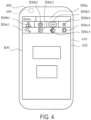
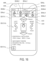
- the emergency stop lamp ID0b3 can also indicate whether or not the robot 100 is in an emergency stop state.
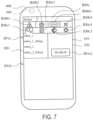
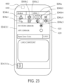
- the operation terminal 400 receives a predetermined input, such as a tap input, on the name of a robot in the target robot field ID1a to select the robot.
- the operation terminal 400 indicates, in the connection target field ID1b, information about the robot whose name has been selected.
- the connection target field ID1b includes a name field ID1b1, a connection button ID1b2 and a disconnection button ID1b3, which indicate a state of connection, a communication mode field ID1b4, and a connection confirmation button ID1b5.
- the name field ID1b1 includes the name and address of the selected robot.
- the operation terminal 400 Upon receiving a predetermined input, such as a tap input, on the connection button ID 1 b2, the operation terminal 400 connects to the robot indicated in the name field ID1b1, and displays the connection button ID 1 b2 in a highlighted manner.
- the operation terminal 400 Upon receiving a predetermined input, such as a tap input, on the disconnection button ID1b3, the operation terminal 400 disconnects from the robot indicated in the name field ID1b1, and displays the disconnection button ID1b3 in a highlighted manner.
- the operation terminal 400 Upon receiving a predetermined input, such as a tap input, on the connection confirmation button ID1b5, the operation terminal 400 transmits a command requesting the connected actual robot 100 for connection confirmation.
- the robot control equipment 200 of the robot 100 Upon receiving the command, the robot control equipment 200 of the robot 100 causes the robot 100 to perform a predetermined action.
- the predetermined action may be an action of the robotic arm 111, an action of the moving equipment 120, turning on of the light sources 124 of the robot 100, or a combination of two or more of these.
- the robot control equipment 200 temporarily turns on the light sources 124.
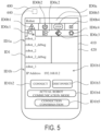
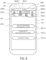
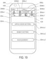
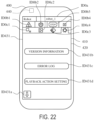
- the operation terminal 400 displays, on an action selection screen ID21, an action selection button ID21a indicating a predetermined action that has been taught, such as work that has been taught.
- the action selection screen ID21 includes at least one action selection button ID21a corresponding to at least one predetermined action.
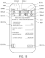
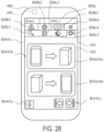
- the operation terminal 400 transitions the screen on the presenter 420 to, for example, a robot operation screen ID22 as shown in FIG. 9.
- FIG. 9 shows one example of the robot operation screen, which is one of the playback operation screens to be displayed on the operation terminal 400.
- FIG. 9 shows one example of the robot operation screen for air conditioner assembling work.
- the ongoing work field ID22a indicates ongoing work, i.e., a predetermined action that is being performed.
- the operation key ID22b may include various keys such as: a key to give a command to perform, and to give a command to stop performing, at least one process included in the work; and a key to give a command to perform, and to give a command to stop performing, a single piece of work.
- the lock button ID22c is a button to switch between a locked state, which is a state of not allowing receiving an input to the robot operation screen ID22, and an unlocked state, which is a state of allowing receiving an input to the robot operation screen ID22.
- the operation terminal 400 may not allow receiving inputs to any of the input elements on the robot operation screen ID22 except the lock button ID22c, or may not allow receiving inputs to some of the input elements.
- the some of the input elements may be those relating to performing an action of the robot 100, such as the operation key ID22b.
- the operation terminal 400 When the operation terminal 400 is in the locked state, upon receiving a predetermined input, such as a long press input, on the lock button ID22c, the operation terminal 400 shifts to the unlocked state, and switches the mode of the lock button ID22c from the one indicating the locked state to the one indicating the unlocked state.
- the operation terminal 400 When the operation terminal 400 is in the unlocked state, if a state of receiving no input to the input elements has continued for a predetermined time, the operation terminal 400 may shift to the locked state, and switch the mode of the lock button ID22c from the one indicating the unlocked state to the one indicating the locked state.
- the above input elements may be unlocked input elements.
- the operation terminal 400 When the operation terminal 400 is in the unlocked state, in addition to the above, or instead of the above, the operation terminal 400 may shift to the locked state upon receiving a predetermined input, such as a long press input, on the lock button ID22c.
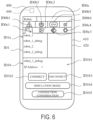
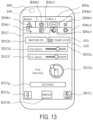
- the lock button ID32i is a button that indicates a locked state and an unlocked state.
- the locked state is a state of not allowing receiving inputs to the input elements on the robot teaching screen ID32
- the unlocked state is a state of allowing receiving inputs to the input elements.
- the lock button ID32i on the operation terminal 400 has the same functionality as the previously exemplified functionality of the lock button ID22c on the robot operation screen ID22.
- the operation terminal 400 may not allow receiving inputs to any of the input elements except the lock button ID32i, or may not allow receiving inputs to some of the input elements.
- the operation terminal 400 may be configured to display, in the state field 331b, a result of detection by the position detector 123. Based on robot information about the robot 100, which is received from the robot control equipment 200, the operation terminal 400 may detect a deviation of the moving equipment 120 from a predetermined track. Examples of the predetermined track may include a target track included in the teaching data and the magnetic material line.
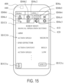
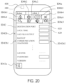
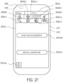
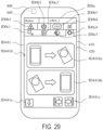
- the operation terminal 400 upon receiving a predetermined input on the selection button ID41a1, displays, for example, the application setting screen ID42 as shown in FIG. 20.
- FIG. 20 shows one example of the application setting screen, which is one of the setting screens ID4 to be displayed on the operation terminal 400.
- the operation terminal 400 displays a caller button ID42a and a setting field ID42b on the application setting screen ID42. Both of these elements are input elements.
- the selection button ID44b is a button to select data management of the operation terminal 400
- the selection button ID43c is a button to select management of input and output of signals to and from the operation terminal 400.
- the caller button ID441a is a button to bring the screen on the presenter 420 back to the management screen ID44, and has the same functionality as that of the previously described caller buttons.
- the target to which the operation terminal 400 outputs data i.e., the output target
- the target from which the operation terminal 400 receives a data input i.e., the input target
- the operation terminal 400 is configured to be connected to one piece of robot control equipment 200.
- the operation terminal 400 may be connected to two or more pieces of robot control equipment 200 concurrently.
- the operation terminal 400 may be configured to, in parallel, transmit and receive commands, information, data, etc. to and from all of the two or more pieces of robot control equipment 200.
- the operation terminal 400 may be configured to select at least one piece of robot control equipment 200 from among the two or more pieces of robot control equipment 200, and to, in parallel, transmit and receive commands, information, data, etc. to and from the at least one piece of robot control equipment 200.
- the operation terminal 400 may be configured to select one piece of robot control equipment 200 from among the two or more pieces of robot control equipment 200, and to transmit and receive commands, information, data, etc. to and from the one piece of robot control equipment 200.
- An operation terminal is an operation terminal for operating a mobile robot.
- the operation terminal performs: receiving an input of a moving operation that is an operation to cause moving equipment included in the robot to perform an action; and outputting, to control equipment that controls an action of the robot, a command to cause the moving equipment to perform the action in accordance with the received moving operation.
- an operation of the moving equipment of the robot can be performed. Performing an operation of the moving equipment of the robot is causing the robot to perform a particular action.
- a manual operation of the moving equipment of the robot is simpler than a manual operation of a robot body such as a robotic arm.
- a manual operation of the moving equipment may be even simpler.
- a smart device such as a tablet may be used as the operation terminal, and the use of the smart device can make the operation even further simpler.
- the operation terminal makes it possible for various operators to perform an operation to cause the robot to perform a particular action.
- the operation terminal may selectively shift between a locked state and an unlocked state, the locked state being a state of not allowing receiving an input of an operation to cause the robot to perform an action, the unlocked state being a state of allowing receiving an input to cause the robot to perform an action.
- the operation terminal may shift to the unlocked state.
- the operation terminal makes it possible to reduce receiving unintentional inputs made by the operator. Therefore, the operation terminal makes it possible to reduce incorrect actions of the robot.
- the operation terminal When the operation terminal according to the above one aspect of the present disclosure is in the unlocked state, if a state of receiving no input of an operation has continued for a predetermined time, the operation terminal may shift to the locked state. According to this aspect, in a case where the state of receiving no input continues, the operation terminal can reduce receiving, from the surrounding environment, unnecessary inputs that are made as a result of the operation terminal coming into contact with the surrounding environment, such as the surrounding physical objects. Therefore, the operation terminal makes it possible to reduce incorrect actions of the robot.
- the operation terminal may include a display.
- the operation terminal may perform: outputting a request for robot information to the control equipment, the robot information being information indicating a state of the robot; and upon receiving the robot information from the control equipment, displaying the robot information on the display.
- the operation terminal can request the control equipment for robot information, and display the robot information obtained from the control equipment in such a manner that the robot information is visible to the operator. This makes it possible for the operator to readily and surely perform an operation of the moving equipment via the operation terminal.
- the operation terminal may receive the input of the moving operation in a case where the robot performs an action that has been taught to the robot in advance.
- the operation terminal can operate the moving equipment. For example, in a case where the position of the robot has deviated from a position that accords with the taught action due to an external disturbance such as a contact with the surrounding environment, the operator can correct the position of the robot by operating the moving equipment via the operation terminal.
- the operation terminal makes it possible for various operators to perform such a correction operation.
- the operation terminal may perform: outputting, to the control equipment, a command to operate in a teaching mode to teach a predetermined action to the moving equipment; receiving the input of the moving operation in the teaching mode; and outputting, to the control equipment, a command to cause the moving equipment to perform the action in accordance with the received moving operation.
- the operation terminal makes it possible to execute the teaching mode to teach the moving equipment and to operate the moving equipment in the teaching mode.
- an action can be taught to the moving equipment by using the operation terminal.
- the operation terminal may perform: receiving an input of an emergency stop command to bring the moving equipment to an emergency stop; and outputting, to the control equipment, a command to cause the moving equipment to stop operation in accordance with the received emergency stop command.
- the moving equipment can be brought to an emergency stop by using the operation terminal.
- the operation terminal may perform: outputting, to at least one piece of control equipment, a request for connectivity for an operation-enabled connection with the operation terminal; upon receiving a response to the request for connectivity for the operation-enabled connection from the control equipment, presenting information about the control equipment that is operable by the operation terminal; receiving an input to select the control equipment to be operated; and outputting, to the control equipment to be operated, a request for the operation-enabled connection with the operation terminal.
- the operation terminal can connect to the control equipment that is selected from various pieces of control equipment.
- the operation terminal can sequentially perform: searching for connectable control equipment; presenting a search result to the operator; and connecting to control equipment that has been selected by the operator from the search result.
- the operation terminal may perform: outputting, to the control equipment, a request for an operation-enabled connection with the operation terminal; and outputting, to the control equipment, a request to clearly indicate, by using the robot, establishment of the operation-enabled connection between the control equipment and the operation terminal.
- the operation terminal can clearly indicate the establishment of the connection between the operation terminal and the control equipment by using the robot, and for example, with visual indication or the like.
- a robot system includes: at least one operation terminal according to the above one aspect of the present disclosure; at least one robot; and at least one piece of control equipment which controls an action of the at least one robot.
- the operation terminal is operably connected to the control equipment selected from the at least one piece of control equipment. According to this aspect, the same advantageous effects as those of the operation terminal according to the above one aspect of the present disclosure are obtained.
- the operation terminal can be connected to the control equipment selected from the at least one piece of control equipment.
- the robot system may further include at least one piece of teaching equipment communicably connected to the at least one piece of control equipment.
- the control equipment may operably and selectively connect to either the operation terminal or the teaching equipment. According to this aspect, the occurrence of the following situation is reduced: during teaching to the robot by using the teaching equipment, the control equipment causes the robot to perform an action in accordance with a command received from the operation terminal. As a result, incorrect actions of the robot are reduced.
- a computer program according to one aspect of the present disclosure is a computer program for causing the operation terminal according to the above one aspect of the present disclosure to operate, the computer program causing the operation terminal to perform: receiving the input of the moving operation; generating an operation command to cause the moving equipment to perform the action in accordance with the received moving operation; and outputting the operation command to the control equipment. According to this aspect, the same advantageous effects as those of the operation terminal according to the above one aspect of the present disclosure are obtained.
- the computer program according to the above one aspect of the present disclosure may be a program that is incorporated in the operation terminal as an application program. According to this aspect, even if the operation terminal is not a dedicated device, but, for example, a general-purpose device, the functionality of the present disclosure can be realized by incorporating the computer program into the operation terminal.
- An operation terminal is an operation terminal for operating a robot.
- the operation terminal is communicably connected to control equipment that controls an action of the robot.
- the operation terminal performs: receiving an input of an operation to cause the robot to perform an action; and outputting a command to the control equipment to cause the robot to perform the action in accordance with the received operation.
- the operation terminal receives a particular operation that is part of operations to cause the robot to perform actions, the operations being receivable by teaching equipment for the robot.
- an operation of the robot receivable by the operation terminal is a particular operation that is part of operations, which are to cause the robot to perform actions and are receivable by the teaching equipment.
- the particular operation may be a simple operation that is one of the operations receivable by the teaching equipment.
- a smart device such as a tablet may be used as the operation terminal, and the use of the smart device can make the particular operation even simpler.
- the operation terminal makes it possible for various operators to perform an operation to cause the robot to perform a particular action.
- the particular operation may be different from an operation to cause the robot to perform an action to perform teaching to the robot.
- the particular operation since the particular operation is different from an operation for teaching, special training for the operator to perform the particular operation can be made unnecessary, and further, the particular operation may be a simple operation. Therefore, the operation terminal makes it possible for various operators to perform an operation to cause the robot to perform a particular action.
- the particular operation may include an operation to cause the robot to perform an action that has been taught to the robot in advance.
- an operation to cause the robot to autonomously perform an action that has been taught to the robot in advance may be a simple operation. This makes it possible to simplify the particular operation.
- the particular operation may include an operation to command the robot to return to a predetermined state that is a state of being in a position of origin.
- the operation to command the robot to return to the state of being in the position of origin may be a simple operation. This makes it possible to simplify the particular operation.
- the operation terminal may include a display.
- the operation terminal may perform: outputting a request for robot information to the control equipment, the robot information being information indicating a state of the robot; and upon receiving the robot information from the control equipment, displaying the robot information on the display.
- the operation terminal may perform: outputting, to at least one piece of control equipment, a request for connectivity for an operation-enabled connection with the operation terminal; upon receiving a response to the request for connectivity for the operation-enabled connection from the control equipment, presenting information about the control equipment that is operable by the operation terminal; receiving an input to select the control equipment to be operated; and outputting, to the control equipment to be operated, a request for the operation-enabled connection with the operation terminal.
- the operation terminal can connect to the control equipment that is selected from various pieces of control equipment.
- the operation terminal can sequentially perform: searching for connectable control equipment; presenting a search result to the operator; and connecting to control equipment that has been selected by the operator from the search result.
- the operation terminal may perform: outputting, to the control equipment, a request for an operation-enabled connection with the operation terminal; and outputting, to the control equipment, a request to clearly indicate, by using the robot, establishment of the operation-enabled connection between the control equipment and the operation terminal.
- the operation terminal can clearly indicate the establishment of the connection between the operation terminal and the control equipment by using the robot, and for example, with visual indication or the like.
- a robot system includes: at least one operation terminal according to the above other aspect of the present disclosure; at least one robot; and at least one piece of control equipment which controls an action of the at least one robot.
- the operation terminal is operably connected to the control equipment selected from the at least one piece of control equipment. According to this aspect, the same advantageous effects as those of the operation terminal according to the above other aspect of the present disclosure are obtained.
- the operation terminal can be connected to the control equipment selected from the at least one piece of control equipment.
- a computer program according to another aspect of the present disclosure is a computer program for causing the operation terminal according to the above other aspect of the present disclosure to operate, the computer program causing the operation terminal to perform: receiving an input of the particular operation; generating an operation command to cause the robot to perform an action in accordance with the received particular operation; and outputting the operation command to the control equipment communicably connected to the operation terminal.
Landscapes
- Engineering & Computer Science (AREA)
- Robotics (AREA)
- Mechanical Engineering (AREA)
- Physics & Mathematics (AREA)
- General Physics & Mathematics (AREA)
- Automation & Control Theory (AREA)
- Human Computer Interaction (AREA)
- Manufacturing & Machinery (AREA)
- Manipulator (AREA)
- Numerical Control (AREA)
Applications Claiming Priority (2)
| Application Number | Priority Date | Filing Date | Title |
|---|---|---|---|
| JP2021141728A JP7813109B2 (ja) | 2021-08-31 | 2021-08-31 | ロボットシステム |
| PCT/JP2022/032600 WO2023032984A1 (ja) | 2021-08-31 | 2022-08-30 | 操作端末、ロボットシステム及びコンピュータプログラム |
Publications (2)
| Publication Number | Publication Date |
|---|---|
| EP4397449A1 true EP4397449A1 (de) | 2024-07-10 |
| EP4397449A4 EP4397449A4 (de) | 2025-08-20 |
Family
ID=85411215
Family Applications (1)
| Application Number | Title | Priority Date | Filing Date |
|---|---|---|---|
| EP22864566.9A Pending EP4397449A4 (de) | 2021-08-31 | 2022-08-30 | Betriebsendgerät, robotersystem und computerprogramm |
Country Status (4)
| Country | Link |
|---|---|
| EP (1) | EP4397449A4 (de) |
| JP (1) | JP7813109B2 (de) |
| CN (1) | CN117794707A (de) |
| WO (1) | WO2023032984A1 (de) |
Family Cites Families (11)
| Publication number | Priority date | Publication date | Assignee | Title |
|---|---|---|---|---|
| DE602005006531D1 (de) * | 2005-04-19 | 2008-06-19 | Comau Spa | Verfahren zur Steuerung von industriellen Robotern und entsprechend gesteuerte Roboter, Robotersysteme und Computerprogramme |
| EP1782928B1 (de) * | 2005-11-08 | 2008-05-07 | Abb Ab | Industrierobotisches System mit mehr als einem Handbediengerät |
| JP2015044280A (ja) * | 2013-07-29 | 2015-03-12 | 株式会社ダイヘン | ロボット制御装置 |
| JP6565151B2 (ja) * | 2014-09-19 | 2019-08-28 | 株式会社デンソーウェーブ | 産業用ロボット操作装置 |
| JP6354496B2 (ja) * | 2014-09-26 | 2018-07-11 | トヨタ自動車株式会社 | ロボット制御方法 |
| JP6514258B2 (ja) * | 2017-03-31 | 2019-05-15 | ファナック株式会社 | ロボットシステム |
| JP6619398B2 (ja) | 2017-07-31 | 2019-12-11 | ファナック株式会社 | 操作端末一体型の機械操作盤及び外付けデバイス |
| JP7041492B2 (ja) * | 2017-10-31 | 2022-03-24 | 川崎重工業株式会社 | ロボットシステム |
| JP2020192621A (ja) * | 2019-05-24 | 2020-12-03 | ファナック株式会社 | ロボットに教示点を教示するための装置、ロボットシステム、及びロボットの教示方法 |
| JP6825686B1 (ja) * | 2019-12-17 | 2021-02-03 | 株式会社安川電機 | 生産システム、生産方法、及びプログラム |
| JP2021115634A (ja) * | 2020-01-22 | 2021-08-10 | Dmg森精機株式会社 | 生産システム |
-
2021
- 2021-08-31 JP JP2021141728A patent/JP7813109B2/ja active Active
-
2022
- 2022-08-30 WO PCT/JP2022/032600 patent/WO2023032984A1/ja not_active Ceased
- 2022-08-30 CN CN202280055930.XA patent/CN117794707A/zh active Pending
- 2022-08-30 EP EP22864566.9A patent/EP4397449A4/de active Pending
Also Published As
| Publication number | Publication date |
|---|---|
| EP4397449A4 (de) | 2025-08-20 |
| JP7813109B2 (ja) | 2026-02-12 |
| WO2023032984A1 (ja) | 2023-03-09 |
| JP2023035109A (ja) | 2023-03-13 |
| CN117794707A (zh) | 2024-03-29 |
Similar Documents
| Publication | Publication Date | Title |
|---|---|---|
| JP7225443B2 (ja) | 飛行ルート生成方法及びプログラム | |
| JP6769659B2 (ja) | 移動体の管理システム、方法、およびコンピュータプログラム | |
| US11220002B2 (en) | Robot simulation device | |
| US9720419B2 (en) | System and method for remote control of unmanned vehicles | |
| US9292015B2 (en) | Universal construction robotics interface | |
| US10166673B2 (en) | Portable apparatus for controlling robot and method thereof | |
| JP2020520008A (ja) | ロボットの動作制御のためのシステムおよび方法 | |
| EP4064055A1 (de) | Funktionssicherheit mit sicherheitsursprung und sicherheitskette | |
| CN114740835B (zh) | 路径规划方法、路径规划装置、机器人和存储介质 | |
| EP4397449A1 (de) | Betriebsendgerät, robotersystem und computerprogramm | |
| EP4397450A1 (de) | Betriebsendgerät, robotersystem und computerprogramm | |
| CN110320903A (zh) | 计算机系统及计算机可读取记录媒体 | |
| US20230419467A1 (en) | A mobile robot system for automated asset inspection | |
| Lin et al. | Research on SLAM intelligent robot based on visual laser fusion | |
| Fattah et al. | Dynamic map generating rescuer offering surveillance robotic system with autonomous path feedback capability | |
| CN110142757A (zh) | 一种控制机器人运动的方法、装置及下位机 | |
| WO2019205062A1 (zh) | 可移动平台的导航传感器检测的方法及相关设备 | |
| JPH0522923B2 (de) | ||
| US20240408752A1 (en) | Information processing device, robot controller, robot control system, and information processing method | |
| US20240139949A1 (en) | Robot, robot control method, article manufacturing method, and storage medium | |
| Deshmukh et al. | Design of an on-board Human-Machine Interface for Hardware Self-Diagnose, Testing and Calibration of a Mobile Robot | |
| Meenatchisundaram et al. | Remote Controled Car using Blynk IoT | |
| Ma et al. | Research on measuring and control system for coal mine rescue robot based on multi-sensor | |
| Nguyen et al. | Semi-autonomous wireless controlled robot | |
| Wong | Fault tolerant behavior-based robots |
Legal Events
| Date | Code | Title | Description |
|---|---|---|---|
| STAA | Information on the status of an ep patent application or granted ep patent |
Free format text: STATUS: THE INTERNATIONAL PUBLICATION HAS BEEN MADE |
|
| PUAI | Public reference made under article 153(3) epc to a published international application that has entered the european phase |
Free format text: ORIGINAL CODE: 0009012 |
|
| STAA | Information on the status of an ep patent application or granted ep patent |
Free format text: STATUS: REQUEST FOR EXAMINATION WAS MADE |
|
| 17P | Request for examination filed |
Effective date: 20240328 |
|
| AK | Designated contracting states |
Kind code of ref document: A1 Designated state(s): AL AT BE BG CH CY CZ DE DK EE ES FI FR GB GR HR HU IE IS IT LI LT LU LV MC MK MT NL NO PL PT RO RS SE SI SK SM TR |
|
| DAV | Request for validation of the european patent (deleted) | ||
| DAX | Request for extension of the european patent (deleted) | ||
| REG | Reference to a national code |
Ref country code: DE Ref legal event code: R079 Free format text: PREVIOUS MAIN CLASS: B25J0005000000 Ipc: B25J0009160000 |
|
| A4 | Supplementary search report drawn up and despatched |
Effective date: 20250722 |
|
| RIC1 | Information provided on ipc code assigned before grant |
Ipc: B25J 9/16 20060101AFI20250716BHEP Ipc: G05B 19/409 20060101ALI20250716BHEP Ipc: B25J 5/00 20060101ALI20250716BHEP Ipc: B25J 9/22 20060101ALI20250716BHEP Ipc: B25J 13/02 20060101ALI20250716BHEP Ipc: G05B 19/42 20060101ALI20250716BHEP Ipc: B25J 19/06 20060101ALI20250716BHEP |