EP4397283A1 - Stent und stentanbringungssystem - Google Patents
Stent und stentanbringungssystem Download PDFInfo
- Publication number
- EP4397283A1 EP4397283A1 EP22864487.8A EP22864487A EP4397283A1 EP 4397283 A1 EP4397283 A1 EP 4397283A1 EP 22864487 A EP22864487 A EP 22864487A EP 4397283 A1 EP4397283 A1 EP 4397283A1
- Authority
- EP
- European Patent Office
- Prior art keywords
- straight
- line
- valley
- peak
- interlocking
- Prior art date
- Legal status (The legal status is an assumption and is not a legal conclusion. Google has not performed a legal analysis and makes no representation as to the accuracy of the status listed.)
- Pending
Links
Images


Classifications
-
- A—HUMAN NECESSITIES
- A61—MEDICAL OR VETERINARY SCIENCE; HYGIENE
- A61F—FILTERS IMPLANTABLE INTO BLOOD VESSELS; PROSTHESES; DEVICES PROVIDING PATENCY TO, OR PREVENTING COLLAPSING OF, TUBULAR STRUCTURES OF THE BODY, e.g. STENTS; ORTHOPAEDIC, NURSING OR CONTRACEPTIVE DEVICES; FOMENTATION; TREATMENT OR PROTECTION OF EYES OR EARS; BANDAGES, DRESSINGS OR ABSORBENT PADS; FIRST-AID KITS
- A61F2/00—Filters implantable into blood vessels; Prostheses, i.e. artificial substitutes or replacements for parts of the body; Appliances for connecting them with the body; Devices providing patency to, or preventing collapsing of, tubular structures of the body, e.g. stents
- A61F2/82—Devices providing patency to, or preventing collapsing of, tubular structures of the body, e.g. stents
- A61F2/86—Stents in a form characterised by the wire-like elements; Stents in the form characterised by a net-like or mesh-like structure
- A61F2/90—Stents in a form characterised by the wire-like elements; Stents in the form characterised by a net-like or mesh-like structure characterised by a net-like or mesh-like structure
-
- A—HUMAN NECESSITIES
- A61—MEDICAL OR VETERINARY SCIENCE; HYGIENE
- A61F—FILTERS IMPLANTABLE INTO BLOOD VESSELS; PROSTHESES; DEVICES PROVIDING PATENCY TO, OR PREVENTING COLLAPSING OF, TUBULAR STRUCTURES OF THE BODY, e.g. STENTS; ORTHOPAEDIC, NURSING OR CONTRACEPTIVE DEVICES; FOMENTATION; TREATMENT OR PROTECTION OF EYES OR EARS; BANDAGES, DRESSINGS OR ABSORBENT PADS; FIRST-AID KITS
- A61F2/00—Filters implantable into blood vessels; Prostheses, i.e. artificial substitutes or replacements for parts of the body; Appliances for connecting them with the body; Devices providing patency to, or preventing collapsing of, tubular structures of the body, e.g. stents
- A61F2/82—Devices providing patency to, or preventing collapsing of, tubular structures of the body, e.g. stents
- A61F2/86—Stents in a form characterised by the wire-like elements; Stents in the form characterised by a net-like or mesh-like structure
- A61F2/88—Stents in a form characterised by the wire-like elements; Stents in the form characterised by a net-like or mesh-like structure the wire-like elements formed as helical or spiral coils
-
- A—HUMAN NECESSITIES
- A61—MEDICAL OR VETERINARY SCIENCE; HYGIENE
- A61F—FILTERS IMPLANTABLE INTO BLOOD VESSELS; PROSTHESES; DEVICES PROVIDING PATENCY TO, OR PREVENTING COLLAPSING OF, TUBULAR STRUCTURES OF THE BODY, e.g. STENTS; ORTHOPAEDIC, NURSING OR CONTRACEPTIVE DEVICES; FOMENTATION; TREATMENT OR PROTECTION OF EYES OR EARS; BANDAGES, DRESSINGS OR ABSORBENT PADS; FIRST-AID KITS
- A61F2/00—Filters implantable into blood vessels; Prostheses, i.e. artificial substitutes or replacements for parts of the body; Appliances for connecting them with the body; Devices providing patency to, or preventing collapsing of, tubular structures of the body, e.g. stents
- A61F2/95—Instruments specially adapted for placement or removal of stents or stent-grafts
-
- D—TEXTILES; PAPER
- D04—BRAIDING; LACE-MAKING; KNITTING; TRIMMINGS; NON-WOVEN FABRICS
- D04C—BRAIDING OR MANUFACTURE OF LACE, INCLUDING BOBBIN-NET OR CARBONISED LACE; BRAIDING MACHINES; BRAID; LACE
- D04C1/00—Braid or lace, e.g. pillow-lace; Processes for the manufacture thereof
- D04C1/06—Braid or lace serving particular purposes
-
- A—HUMAN NECESSITIES
- A61—MEDICAL OR VETERINARY SCIENCE; HYGIENE
- A61F—FILTERS IMPLANTABLE INTO BLOOD VESSELS; PROSTHESES; DEVICES PROVIDING PATENCY TO, OR PREVENTING COLLAPSING OF, TUBULAR STRUCTURES OF THE BODY, e.g. STENTS; ORTHOPAEDIC, NURSING OR CONTRACEPTIVE DEVICES; FOMENTATION; TREATMENT OR PROTECTION OF EYES OR EARS; BANDAGES, DRESSINGS OR ABSORBENT PADS; FIRST-AID KITS
- A61F2220/00—Fixations or connections for prostheses classified in groups A61F2/00 - A61F2/26 or A61F2/82 or A61F9/00 or A61F11/00 or subgroups thereof
- A61F2220/0008—Fixation appliances for connecting prostheses to the body
-
- A—HUMAN NECESSITIES
- A61—MEDICAL OR VETERINARY SCIENCE; HYGIENE
- A61F—FILTERS IMPLANTABLE INTO BLOOD VESSELS; PROSTHESES; DEVICES PROVIDING PATENCY TO, OR PREVENTING COLLAPSING OF, TUBULAR STRUCTURES OF THE BODY, e.g. STENTS; ORTHOPAEDIC, NURSING OR CONTRACEPTIVE DEVICES; FOMENTATION; TREATMENT OR PROTECTION OF EYES OR EARS; BANDAGES, DRESSINGS OR ABSORBENT PADS; FIRST-AID KITS
- A61F2230/00—Geometry of prostheses classified in groups A61F2/00 - A61F2/26 or A61F2/82 or A61F9/00 or A61F11/00 or subgroups thereof
- A61F2230/0063—Three-dimensional shapes
- A61F2230/0069—Three-dimensional shapes cylindrical
-
- A—HUMAN NECESSITIES
- A61—MEDICAL OR VETERINARY SCIENCE; HYGIENE
- A61F—FILTERS IMPLANTABLE INTO BLOOD VESSELS; PROSTHESES; DEVICES PROVIDING PATENCY TO, OR PREVENTING COLLAPSING OF, TUBULAR STRUCTURES OF THE BODY, e.g. STENTS; ORTHOPAEDIC, NURSING OR CONTRACEPTIVE DEVICES; FOMENTATION; TREATMENT OR PROTECTION OF EYES OR EARS; BANDAGES, DRESSINGS OR ABSORBENT PADS; FIRST-AID KITS
- A61F2240/00—Manufacturing or designing of prostheses classified in groups A61F2/00 - A61F2/26 or A61F2/82 or A61F9/00 or A61F11/00 or subgroups thereof
- A61F2240/001—Designing or manufacturing processes
- A61F2240/002—Designing or making customized prostheses
-
- A—HUMAN NECESSITIES
- A61—MEDICAL OR VETERINARY SCIENCE; HYGIENE
- A61F—FILTERS IMPLANTABLE INTO BLOOD VESSELS; PROSTHESES; DEVICES PROVIDING PATENCY TO, OR PREVENTING COLLAPSING OF, TUBULAR STRUCTURES OF THE BODY, e.g. STENTS; ORTHOPAEDIC, NURSING OR CONTRACEPTIVE DEVICES; FOMENTATION; TREATMENT OR PROTECTION OF EYES OR EARS; BANDAGES, DRESSINGS OR ABSORBENT PADS; FIRST-AID KITS
- A61F2310/00—Prostheses classified in A61F2/28 or A61F2/30 - A61F2/44 being constructed from or coated with a particular material
- A61F2310/00005—The prosthesis being constructed from a particular material
- A61F2310/00011—Metals or alloys
Definitions
- Patent Document 1 United States Patent No. 6,974,472
- the stent described in Patent Document 1 is constructed by weaving a single wire. Therefore, the portions where the straight wires intersect each other (straight-line crossing portions 70) are positioned adjacent to the interlocking portions 60 in the circumferential direction of the stent. When the stent is bent, the interlocking portion 60 can bend to follow, but the straight-line crossing portion 70 generates a force (axial force) that opposes bending. Therefore, the shape followability of the stent as a whole is impaired. In particular, it is difficult to place a stent in a place where the shape of the lumen is greatly curved. Alternatively, even if the placement is successful, the lumen tends to conform to the shape of the stent, which may put a strain on the lumen, or may cause problems such as the stent moving from the placement position.
- an object of the present invention is to provide a stent that is easy to bend and maintain a bent state, and a stent delivery system that includes the stent.
- the present invention proposes the following means.
- a stent according to a first aspect of the present invention is a stent formed by weaving wires, including: a plurality of straight-line crossing portions, which are formed by crossing at least two straight-line portions of the wires and are arranged adjacent to each other in a circumferential direction of the stent; and a plurality of interlocking portions configured by intersecting a peak-shaped bent portion, in which the wire is bent in a first direction side which is one side of a longitudinal axis direction of the stent and becomes convex, and a valley-shaped bent portion, in which the wire is bent in a second direction side which is the other side of the longitudinal axis direction and becomes convex, and arranged so as to be adjacent to each other in the circumferential direction of the stent, wherein the interlocking portions and the straight-line crossing portions are arranged alternately in the longitudinal axis direction.
- the stent of the present invention is easy to bend, and it is easy to maintain a bent state.
- the endoscope 200 is a known side-viewing flexible endoscope, and includes an elongated insertion portion 210 and an operation portion 220 provided at the proximal end of the insertion portion 210. Note that the endoscope 200 may be a direct-view flexible endoscope.
- the insertion portion 210 is formed with a treatment instrument channel 230 through which an endoscopic treatment instrument such as the stent delivery system 150 is inserted.
- a distal end portion 230a of the treatment instrument channel 230 is open on the side surface of the distal end rigid portion 211.
- a proximal end portion of the treatment instrument channel 230 extends to the operation portion 220.
- the bent portion 212 is configured to be freely bendable in the vertical and horizontal directions.
- the distal end of the operation wire is fixed to the distal end side of the bent portion 212.
- the operation wire extends through the insertion portion 210 to the operation portion 220.
- a knob 223 for operating the operation wire and a switch 224 for operating the imaging unit 216 and the like are provided on the proximal end side of the operation portion 220. The user can bend the bent portion 212 in a desired direction by operating the knob 223.
- the outer tubular member 110 is made of resin or the like in a cylindrical shape and has flexibility.
- the outer tubular member 110 can be inserted through the treatment instrument channel 230 of the endoscope 200.
- the inner tubular member 120 has an outer diameter smaller than the inner diameter of the outer tubular member 110 and can be passed through the inner space (lumen) of the outer tubular member 110.
- the inner tubular member 120 is made of resin or the like and has flexibility.
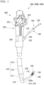
- a tip 130 having an outer diameter larger than that of the outer tubular member 110 is provided at the tip of the inner tubular member 120.
- the operation portion 140 is connected to the proximal end sides of the outer tubular member 110 and the inner tubular member 120, and is configured to allow the outer tubular member 110 to move relative to the inner tubular member 120 in the longitudinal direction.
- the operator moves the outer tubular member 110 with respect to the inner tubular member 120 to expose the accommodated stent 100, and as a result, the stent 100 can be placed.
- the operator can move the outer tubular member 110 in the opposite direction relative to the inner tubular member 120, thereby allowing the stent 100 to be re-accommodated.
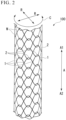
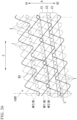
- FIG. 2 is a diagram showing the overall configuration of the stent 100.
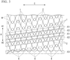
- FIG. 3 is a developed view of the stent 100 deployed in the circumferential direction C.
- first regions E1 in which the plurality of straight-line crossing portions 1 are arranged and second regions E2 in which the plurality of interlocking portions 2 are arranged are alternately arranged in the longitudinal axis direction A.
- Each first region E1 is spirally arranged along the longitudinal axis direction A.
- each second region E2 is spirally arranged along the longitudinal axis direction A.
- the end portion of the valley-shaped bent portion 4 in the end region E3 on the second direction A2 side may be arranged spirally without intersecting the peak-shaped bent portion 3 as shown in FIG. 3 , and may be aligned with respect to the longitudinal axis direction A.
- the positions of the ends with respect to the longitudinal axis direction A can be aligned by adjusting the length of the longitudinal axis direction A of the peak-shaped bent portion 3 and the valley-shaped bent portion 4 in the end region.
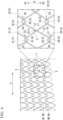
- the first straight-line portion 11 and the second straight-line portion 12 intersect at the central straight-line crossing portion 1A.
- the first straight-line portion 11 passes outside the second straight-line portion 12 in the radial direction R.
- the first peak 31 and the first valley 41 intersect at a first crossing portion C1 and a second crossing portion C2 closer to the central straight-line crossing portion 1A than the first crossing portion C1.
- the first peak 31 passes through the outer side of the first valley 41 in the radial direction R.
- the second crossing portion C2 the first peak 31 passes through the inner side of the first valley 41 in the radial direction R.
- a “second peak 32”, which is the peak-shaped bent portion 3, is connected to the first direction A1 side of the second straight-line portion 12.
- the second peak 32 intersects with a second valley 42 that is the valley-shaped bent portion 4 to form the "second interlocking portion 22" that is the interlocking portion 2.
- a "third valley 43" which is the valley-shaped bent portion 4, continues.
- the third valley 43 intersects with a third peak 33 that is the peak-shaped bent portion 3 to form the "third interlocking portion 23" that is the interlocking portion 2.
- a "fourth valley 44" which is the valley-shaped bent portion 4
- the fourth valley 44 intersects with a fourth peak 34 that is the peak-shaped bent portion 3 to form the "fourth interlocking portion 24" that is the interlocking portion 2.
- the fourth peak 34 and the fourth valley 44 intersect at an eighth crossing portion C8 and a seventh crossing portion C7 closer to the central straight-line crossing portion 1A than the eighth crossing portion C8.
- the fourth valley 44 passes outside the fourth peak 34 in the radial direction R at the seventh crossing portion C7.
- the fourth valley 44 passes inside the fourth peak 34 in the radial direction R at the fourth crossing portion C4.
- the first interlocking portion 21 and the second interlocking portion 22 are arranged at different positions in the longitudinal axis direction A. Specifically, the second interlocking portion 22 is arranged on the first direction A1 side of the first interlocking portion 21 in the longitudinal axis direction A. Also, the first interlocking portion 21 is arranged in the longitudinal axis direction A between the second interlocking portion 22 and the central straight-line crossing portion 1A.
- the third interlocking portion 23 and the fourth interlocking portion 24 are arranged at different positions in the longitudinal axis direction A. Specifically, the third interlocking portion 23 is arranged on the first direction A1 side of the fourth interlocking portion 24 in the longitudinal axis direction A. Further, the third interlocking portion 23 is arranged between the central straight-line crossing portion 1A and the fourth interlocking portion 24 in the longitudinal axis direction A.
- the central straight-line crossing portion 1A is arranged between the first interlocking portion 21 and the second interlocking portion 22 in the circumferential direction C. Further, the central straight-line crossing portion 1A is arranged between the third interlocking portion 23 and the fourth interlocking portion 24 in the circumferential direction C.
- the first peak 31, the first straight-line portion 11, and the third valley 43 are continuous parts of the wire W extending in a zigzag along the circumferential direction C, and are parts of the wire W indicated by broken lines in FIG. 4 .
- the wire W indicated by the dashed line in FIG. 4 is also referred to as "first wire W1".
- FIG. 5 is a diagram showing the crossing portion of the first straight-line portion 11 and another wire W.
- the central straight-line crossing portion 1A and the four interlocking portions 2 (the first interlocking portion 21, the second interlocking portion 22, the third interlocking portion 23 and the fourth interlocking portion 24) connected to the central straight-line crossing portion 1A have the above configuration.
- the other straight-line crossing portion 1 in the stent 100 and the four interlocking portions 2 connected to the straight-line crossing portion 1 have the same configuration.
- the operator inserts the insertion portion 210 of the endoscope 200 into the patient's body cavity through a natural opening such as the mouth. At that time, the operator bends the bent portion 212 by operating the knob 223 or the like as necessary.
- the placement procedure of the stent 100 is completed.
- FIG. 8 is a diagram showing another modification of the wire W crossing mode.
- FIG. 9 is a diagram showing crossing portions of the first straight-line portion 11 and another wire W in another modification.
- the first straight-line portion 11 has the first peak 31 continuous in the first direction A1 passing outside the first valley 41 in the radial direction R at the second crossing portion C2.
- the third valley 43 continuous in the second direction A2 passes inside the third peak 33 in the radial direction R at the third crossing portion C3.
- the frictional force of the wires W intersecting at the second crossing portion C2, the third crossing portion C3, and the central straight-line crossing portion 1C becomes smaller than in the above embodiment, and larger than that in Modification 1-1.
- a second embodiment of the present invention will be described with reference to FIG. 10 .
- the same reference numerals are given to the same configurations as those already described, and redundant descriptions will be omitted.
- a stent 100B according to the second embodiment is housed in a stent delivery system 150, like the stent 100 according to the first embodiment.
- the central straight-line crossing portion 1A of the stent 100 according to the first embodiment will be referred to as "first straight-line crossing portion 1A" in the following description.
- first straight-line crossing portion 1A the first peak 31 extending in the first direction A1 passes inside the first valley 41 in the radial direction R at the second crossing portion C2.
- the third valley 43 extending in the second direction A2 passes inside the third peak 33 in the radial direction R at the third crossing portion C3.
- the stent 100B has a plurality of straight-line crossing portions 1 and a plurality of interlocking portions 2, like the stent 100 according to the first embodiment.
- the plurality of straight-line crossing portions 1 include a first straight-line crossing portion 1A and a second straight-line crossing portion 1B.
- the first straight-line crossing portion 1A is arranged continuously in the longitudinal axis direction A. Two or three first straight-line crossing portions 1A are continuously arranged in the circumferential direction C. Moreover, the second straight-line crossing portion 1B is arranged continuously in the longitudinal axis direction A. Two or three second straight-line crossing portions 1B are continuously arranged in the circumferential direction C. Further, the first straight-line crossing portions 1A and the second straight-line crossing portions 1B are alternately arranged in the circumferential direction C.
- the stent 100C has the plurality of straight-line crossing portions 1 and the plurality of interlocking portions 2, like the stent 100 according to the first embodiment.
- the plurality of straight-line crossing portions 1 include a first straight-line crossing portion 1A and a second straight-line crossing portion 1B.
- the first straight-line crossing portion 1A and the second straight-line crossing portion 1B are alternately arranged one by one in the longitudinal axis direction A. Also, the first straight-line crossing portion 1A and the second straight-line crossing portion 1B are alternately arranged in the circumferential direction C one by one.
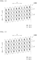
- FIG. 15 is a diagram showing a stent 100C1 that is a modification of the arrangement of the first straight-line crossing portion 1A and the second straight-line crossing portion 1B.
- the first straight-line crossing portion 1A and the second straight-line crossing portion 1B are alternately arranged in the longitudinal axis direction A one by one.
- the stent 100C1 includes a second region E2A in which one first straight-line crossing portion 1A and two continuous second straight-line crossing portions 1B are arranged in the circumferential direction C, and a second region E2B in which two consecutive first straight-line crossing portions 1A and one second straight-line crossing portion 1B are arranged in the circumferential direction C.
- the second region E2A and the second region E2B are alternately arranged in the longitudinal direction A one by one.
- the stent 100C1 has higher shape followability than the stent 100C.
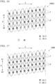
- FIG. 16 is a diagram showing a stent 100C2 that is a modification of the arrangement of the first straight-line crossing portion 1A and the second straight-line crossing portion 1B.
- Three or four first straight-line crossing portions 1A are continuously arranged in the circumferential direction C.
- three or four second straight-line crossing portions 1B are continuously arranged in the circumferential direction C.
- the stent 100C2 can achieve both high shape followability and high shape retention.
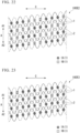
- FIG. 17 is a developed view of the stent 100D deployed in the circumferential direction C.
- the stent 100D has a plurality of straight-line crossing portions 1 and a plurality of interlocking portions 2, like the stent 100 according to the first embodiment.
- the plurality of straight-line crossing portions 1 include a first straight-line crossing portion 1A and a second straight-line crossing portion 1B.
- the first straight-line crossing portions 1A are arranged continuously in the circumferential direction C. Moreover, the second straight-line crossing portion 1B is arranged continuously in the circumferential direction C. The first straight-line crossing portions 1A and the second straight-line crossing portions 1B are alternately arranged in the longitudinal axis direction A.
- the first straight-line crossing portions 1A where the frictional force of the crossing wires W is high are arranged continuously in the circumferential direction C, so that it is easy to maintain a certain shape retention.
- the stent 100D can partially retain a portion having a very high shape followability while maintaining a certain shape retention property.
- FIG. 18 is a diagram showing a stent 100D1 that is a modification of the arrangement of the first straight-line crossing portion 1A and the second straight-line crossing portion 1B.
- the first straight-line crossing portions 1A are alternately arranged in the circumferential direction C.
- the second straight-line crossing portion 1B is not arranged continuously in the circumferential direction C.
- the second straight-line crossing portions 1B and the first straight-line crossing portions 1A are alternately arranged in the circumferential direction C one by one.
- the stent 100D1 can partially retain a portion with extremely high shape followability while maintaining constant shape retention.
- FIG. 19 is a diagram showing a stent 100D2 that is a modification of the arrangement of the first straight-line crossing portion 1A and the second straight-line crossing portion 1B.
- the first straight-line crossing portions 1A are arranged continuously in the circumferential direction C.
- the second straight-line crossing portion 1B is not continuously arranged in the circumferential direction C.
- the five continuous second straight-line crossing portions 1B are arranged adjacent to the five continuous first straight-line crossing portions 1A in the circumferential direction C.
- the part where the second straight-line crossing portion 1B where the frictional force of the intersecting wires W is low is arranged intensively becomes a part that is easily curved.
- the stent 100D2 can partially enhance shape followability while maintaining high shape retention in a curved state.
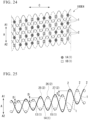
- a fifth embodiment of the present invention will be described with reference to FIG. 20 .
- the same reference numerals are given to the same configurations as those already described, and redundant descriptions will be omitted.
- a stent 100E according to the fifth embodiment differs from the stent 100B according to the second embodiment only in the arrangement of the first straight-line crossing portion 1A and the second straight-line crossing portion 1B.
- FIG. 20 is a developed view of the stent 100E deployed in the circumferential direction C.
- the stent 100E has a plurality of straight-line crossing portions 1 and a plurality of interlocking portions 2, like the stent 100 according to the first embodiment.
- the plurality of straight-line crossing portions 1 include a first straight-line crossing portion 1A and a second straight-line crossing portion 1B.
- the two first straight-line crossing portions 1A continuous in the circumferential direction C are arranged spirally along the longitudinal axis direction A. Further, three second straight-line crossing portions 1B continuous in the circumferential direction C are arranged spirally along the longitudinal axis direction A.
- FIG. 22 is a diagram showing a stent 100E2 that is a modification of the arrangement of the first straight-line crossing portion 1A and the second straight-line crossing portion 1B.
- the three first straight-line crossing portions 1A continuous in the circumferential direction C are arranged spirally along the longitudinal axis direction A. Further, three second straight-line crossing portions 1B continuous in the circumferential direction C are arranged spirally along the longitudinal axis direction A.
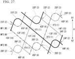
- FIG. 27 is an enlarged view of region R3 shown in FIG. 26 .
- the second interlocking portion 22F and the third interlocking portion 23F are adjacent to each other in the circumferential direction C and arranged at different positions in the longitudinal direction A. Specifically, the third interlocking portion 23F is arranged on the first direction A1 side in the longitudinal axis direction A from the second interlocking portion 22F.
- the stent 100F of the present embodiment includes a plurality of interlocking portions 2, and has high shape followability even when bent.
- the force (axial force) against bending is reduced.
- the stent 100F has more straight-line crossing portions 1 than the stent 100 of the first embodiment, friction of the strut is likely to occur between the straight-line crossing portion 1 and the interlocking portion 2 when the entire stent is bent, and the shape retention is high.
- the first regions E1 in which the plurality of straight-line crossing portions 1 are arranged and the second regions E2 in which the plurality of interlocking portions 2 are arranged are alternately arranged in the longitudinal axis direction A.
- the first region E1 is spirally arranged along the longitudinal axis direction A.
- the second region E2 is spirally arranged along the longitudinal axis direction A.
- the first straight-line portion 11G and the second straight-line portion 12G which are the straight-line portions 10, intersect at the "first straight-line crossing portion 1G1", which is the straight-line crossing portion 1, when viewed from the radial direction R of the stent 100G.
- the first straight-line portion 11G and the fourth straight-line portion 14G which are the straight-line portions 10, intersect at the "third straight-line crossing portion 1G3", which is the straight-line crossing portion 1, when viewed from the radial direction R of the stent 100G.
- the third straight-line crossing portion 1G3 is arranged on the second direction A2 side with respect to the second straight-line crossing portion 1G2.
- the fourth straight-line crossing portion 1G4 is arranged on the first direction A1 side with respect to the second straight-line crossing portion 1G2.
- the second straight-line portion 12G and the sixth straight-line portion 16G which are the straight-line portions 10, intersect at the "sixth straight-line crossing portion 1G6", which is the straight-line crossing portion 1, when viewed from the radial direction R of the stent 100G.
- the sixth straight-line crossing portion 1G6 is arranged on the second direction A2 side with respect to the first straight-line crossing portion 1G1 and on the first direction A1 side with respect to the fifth straight-line crossing portion 1G5.
- the first straight-line crossing portion 1G1, the second straight-line crossing portion 1G2, the third straight-line crossing portion 1G3, the fourth straight-line crossing portion 1G4, the fifth straight-line crossing portion 1G5, the sixth straight-line crossing portion 1G6 and the seventh straight-line crossing portion 1G7 are arranged in the same first region E1.
- a “second peak 32G”, which is the peak-shaped bent portion 3, is connected to the first direction A1 side of the second straight-line portion 12G and the fifth straight-line portion 15G.
- the second peak 32G intersects with the second valley 42G, which is the valley-shaped bent portion 4, to form the "second interlocking portion 22G", which is the interlocking portion 2.
- a “third peak 33G”, which is the peak-shaped bent portion 3, is connected to the first direction A1 side of the third straight-line portion 13G.
- the third peak 33G intersects with the third valley 43G, which is the valley-shaped bent portion 4, to form the "third interlocking portion 23G", which is the interlocking portion 2.
- the “fourth valley 44G”, which is the valley-shaped bent part 4, is connected to the second direction A2 side of the first straight-line portion 11G.
- the fourth valley 44G intersects with the fourth peak 34G, which is the peak-shaped bent portion 3, to form the "fourth interlocking portion (lower interlocking portion) 24G", which is the engaging section 2.
- the fifth valley 45G intersects with the fifth peak 35G, which is the peak-shaped bent portion 3, to form the "fifth hook portion 25G", which is the hook portion 2.
- the sixth valley 46G intersects with the sixth peak 36G, which is the peak-shaped bent portion 3, to form the "sixth interlocking portion 26G", which is the interlocking portion 2.
- the first straight-line portion 11G connects with the first interlocking portion (upper interlocking portion) 21G on the first direction A1 side, and connects with the fourth interlocking portion (lower interlocking portion) 24G on the second direction A2 side.
- the first straight-line portion 11G and the other three straight-line portions 10 constitute the straight-line crossing portions 1 (first straight-line crossing portion 1G1, second straight-line crossing portion 1G2, third straight-line crossing portion 1G3), respectively.
- the first interlocking portion 21G, the second interlocking portion 22G, and the third interlocking portion 23G are arranged along the circumferential direction C and arranged in the same second region E2.
- the first interlocking portion 21G and the second interlocking portion 22G are adjacent to each other in the circumferential direction C and arranged at different positions in the longitudinal direction A. Specifically, the second interlocking portion 22G is arranged on the first direction A1 side in the longitudinal axis direction A from the first interlocking portion 21G.
- the second interlocking portion 22G and the third interlocking portion 23G are adjacent to each other in the circumferential direction C and arranged at different positions in the longitudinal direction A. Specifically, the third interlocking portion 23G is arranged on the first direction A1 side in the longitudinal axis direction A from the second interlocking portion 22G.
- the fourth interlocking portion 24G, the fifth interlocking portion 25G, and the sixth interlocking portion 26G are arranged along the circumferential direction C and arranged in the same second region E2.
- the fifth interlocking portion 25G and the sixth interlocking portion 26G are adjacent to each other in the circumferential direction C and arranged at different positions in the longitudinal direction A. Specifically, the sixth interlocking portion 26G is arranged on the second direction A2 side in the longitudinal axis direction A from the fifth interlocking portion 25G.
- the first peak 31G, the first straight-line portion 11G, and the fourth valley 44G are a continuous part of the wire W extending in a zigzag along the circumferential direction C (first wire WG1).
- the sixth valley 46G, the third straight-line portion 13G, and the third peak 33G are a continuous part of the wire W extending in a zigzag along the circumferential direction C (second wire WG2).
- the second straight-line portion 12G, the second peak 32G, and the fifth straight-line portion 15G are continuous parts of the wire W extending in a zigzag along the circumferential direction C (third wire WG3).
- the sixth straight-line portion 16G, the fifth valley 45G, and the fourth straight-line portion 14G are continuous portions of the wire W extending in a zigzag along the circumferential direction C (fourth wire WG4).
- the first wire WG1, the second wire WG2, the third wire WG3, and the fourth wire WG4 may be one continuous wire, or may be different wires.
- the first valley 41G and the fourth peak 34G are formed by the first wire WG1
- the third valley 43G and the sixth peak 36G are formed by the second wire WG2
- the second valley 42G is formed by the third wire WG3
- the fifth peak 35G is formed by the fourth wire WG4.
- the stent 100G of the present embodiment has a plurality of interlocking portions 2 and has high shape followability even when bent.
- the force (axial force) against bending is reduced.
- the stent 100G has more straight-line crossing portions 1 than the stent 100F of the sixth embodiment, when the stent as a whole is bent, strut friction is likely to occur between the linear crossing portion 1 and the interlocking portion 2, resulting in higher shape retention.
- the first straight-line portion 11F and the other two straight-line portions 10 constitute the straight-line crossing portions 1 (the first straight-line crossing portion 1F 1 and the second straight-line crossing portion 1F2) respectively.
- the first straight line portion 11G and the other three straight line portions 10 respectively constitute the straight-line portion portions 1 (the first straight-line portion 1G1, the second straight-line portion 1G2, and the third straight-line portion 1G3).
- the first straight-line portion may form the straight-line crossing portions 1 with four or more other straight-line portions 10 between the first interlocking portion (upper interlocking portion) and the fourth interlocking portion (lower interlocking portion).
- FIG. 30 is an exploded view of a stent 100G1 that is a modification of the stent 100G.
- the straight-line crossing portion 1 of the stent 100G is replaced with an interlocking portion 2 (hereinafter also referred to as "replacement interlocking portion 1R").
- replacement interlocking portion 1R an interlocking portion 2
- the ends of the valley-shaped bent portion 4 on the second direction A2 side are arranged in a spiral shape without crossing the peak-shaped bent portion 3 as shown in FIG. 30 , or may be aligned with each other in the longitudinal axis direction A.
- the positions of the ends with respect to the longitudinal axis direction A can be aligned.
- a stent 100H according to the eighth embodiment is housed in a stent delivery system 150, like the stent 100 according to the first embodiment.
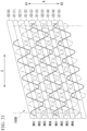
- FIG. 31 is a developed view of the stent 100H deployed in the circumferential direction C.
- the stent 100H is formed in the shape of a circular tube having meshes on its peripheral surface by means of wires W that extend obliquely in the circumferential direction C while repeatedly bending.
- the stent 100H has a plurality of straight-line crossing portions 1 and a plurality of interlocking portions 2.
- the first regions E1 in which the plurality of straight-line crossing portions 1 are arranged and the second regions E2 in which the plurality of interlocking portions 2 are arranged are alternately arranged in the longitudinal axis direction A.
- the first region E1 is spirally arranged along the longitudinal axis direction A.
- the second region E2 is spirally arranged along the longitudinal axis direction A.
- the first region E1 and the second region E2 which are alternately arranged along the longitudinal axis direction A toward the second direction A2, are distinguished as second region E2(0), first region E1(1), second region E2(1), first region E1(2), second region E2(2), first region E1(3), second region E2(3), first region E1(4) and a second region E2(4).
- the first region E1(n) is arranged on the first direction A1 side
- the first region E1(n+1) is arranged on the second direction A2 side, wherein n is an integer.
- a straight-line crossing portion 1 is formed by two wires W (first wire WH1 and second wire WH2), similar to the stent 100 of the first embodiment.
- a straight-line crossing portion 1 is formed by two wires W (third wire WH3 and fourth wire WH4), similar to the stent 100 of the first embodiment.
- the two wires W forming the first region E1(2) are both different from the wires W forming the first region E1(1).
- a straight-line crossing portion 1 is formed by two wires W (first wire WH1 and second wire WH2), similar to the stent 100 of the first embodiment.
- the two wires W forming the first region E1(3) are both the same as the wires W forming the first region E1(1).
- a straight-line crossing portion 1 is formed by two wires W (third wire WH3 and fourth wire WH4), like the stent 100 of the first embodiment.
- the two wires W forming the first region E1(4) are both the same as the wires W forming the first region E1(2).
- the first regions E1 arranged on both sides in the longitudinal direction A with the first region E2 interposed therebetween are formed of different wires W.
- the first regions E1 formed of different wire groups W are alternately arranged in the longitudinal axis direction A.
- the ends of the peak-shaped bent portion 3 on the first direction A1 side may be spirally arranged without intersecting the valley-shaped bent portion 4 as in the E2(0) region of FIG. 31 , or may be arranged so as to align their positions with respect to the longitudinal axis direction A.
- the positions of the ends with respect to the longitudinal direction A can be aligned.
- the ends of one end region of stent 100H can be aligned by adjusting the length of one wire group.
- the ends of the other end region of stent 100H can be aligned by adjusting the length of the other wire group.
- the stent 100H of the present embodiment has a plurality of interlocking portions 2 and has a high shape followability even when it is bent. Since the stent 100H does not need to arrange the straight-line crossing portion 1 at a position adjacent to the interlocking portion 2 in the circumferential direction C, the force (axial force) against bending is reduced.
- first regions E1 formed by different wire groups W are alternately arranged in the longitudinal axis direction A.
- the arrangement mode of the first regions E1 formed by different wire groups W is not limited to this.
- Three or more types of first regions E1 formed of different wire groups W may be alternately arranged in the longitudinal axis direction A.
- Two or more types of first regions E1 formed of different wire groups W may be arranged irregularly in the longitudinal axis direction A.
- a ninth embodiment of the present invention will be described with reference to FIG. 32 .
- the same reference numerals are given to the same configurations as those already described, and redundant descriptions will be omitted.
- a stent 100I according to the ninth embodiment is housed in a stent delivery system 150, like the stent 100 according to the first embodiment.
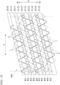
- FIG. 32 is a developed view of the stent 100I deployed in the circumferential direction C.
- the stent 100I is formed in the shape of a circular tube having meshes on its peripheral surface by means of wires W that extend obliquely in the circumferential direction C while repeating bending.
- the stent 100I has a plurality of straight-line crossing portions 1 and a plurality of interlocking portions 2.
- first regions E1 in which a plurality of straight-line crossing portions 1 are arranged and second regions E2 in which a plurality of interlocking portions 2 are arranged are alternately arranged in the longitudinal axis direction A.
- the first region E1 is spirally arranged along the longitudinal axis direction A.
- the second region E2 is spirally arranged along the longitudinal axis direction A.
- the first region E1 and the second region E2 which are alternately arranged in the second direction A2 along the longitudinal axis direction A, are distinguished as second region E2 (0), first region E1(1), second region E2(1), first region E1(2), second region E2(2), first region E1(3), second region E2(3), first region E1(4) and second region E2(4).
- the first region E1(n) is arranged on the first direction A1 side
- the first region E1(n+1) is arranged on the second direction A2 side, wherein n is an integer.
- a straight-line crossing portion 1 is formed by two wires W (first wire WI1 and second wire WI2), like the stent 100 of the first embodiment.
- a straight-line crossing portion 1 is formed by three wires W (the third wire WI3, the second wire WI4, and the fifth wire WI5), as in the stent 100F of the sixth embodiment.
- the wire W forming the first region E1(2) is different from the wire W forming the first region E1(1).
- the number (three) of overlapping wires W forming the first region E1(2) is different from the number (two) of overlapping wires W forming the first region E1(1).
- a straight-line crossing portion 1 is formed by two wires W (first wire WI1 and second wire WI2), like the stent 100 of the first embodiment.
- the two wires W forming the first region E1(3) are both the same as the wires W forming the first region E1(1).
- the number (two) of overlapping wires W forming the first region E1(3) is the same as the number (two) of overlapping wires W forming the first region E1(1).
- a straight-line crossing portion 1 is formed by three wires W (third wire WI3, second wire WI4, and fifth wire WI5) in the same manner as the stent 100F of the sixth embodiment.
- the three wires W forming the first region E1(4) are the same as the wires W forming the first region E1(2).
- the number (three) of overlapping wires W forming the first region E1(4) is the same as the number (three) of overlapping wires W forming the first region E1(3).
- the first regions E1 arranged on both sides in the longitudinal direction A with the first region E2 interposed therebetween are formed of different wires W and formed by different wire weaving methods.
- the first regions E1 formed by different weaving methods of the wires W are alternately arranged in the longitudinal axis direction A.
- the end portions of the first direction A1 side of the peak-shaped bent portion 3 may be arranged in a spiral shape without intersecting with the valley-shaped bent portion 4 as shown in the E2(0) region of FIG. 32 , and may be arranged so as to align their positions with respect to the longitudinal axis direction A.
- the first wire W1 and the second wire W2 (see FIG. 4 ) forming the stent 100 are two different wires W.
- a jig as described in US Pat. No. 6,974,472 is used.
- the jig is formed in a cylindrical shape and has a plurality of projecting pins on its outer periphery.
- protruding pins are provided at locations where the interlocking portions 2 of the stent 100 are formed, and are spirally arranged along the longitudinal axis direction.
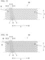
- FIG. 34 is a developed view of the knitted first wire W 1 and second wire W2 developed in the circumferential direction C.
- the operator weaves the second wire W2 along a columnar jig provided with a plurality of projecting pins spirally.
- the operator weaves the second wire W2 in a zigzag pattern, so as to form the second region E2(n-1) and the rest of the interlocking portion 2 of the second region E2(n) on both sides in the longitudinal direction A across the first region E1(n).
- an even number of interlocking portions 2 are arranged for each second region E2(n).
- twelve interlocking portions 2 are arranged for each second region E2(n).
- the knitting method of the stent by the stent manufacturing method of the present embodiment is also called "even number knitting".
- FIGS. 35 to 38 An eleventh embodiment of the present invention will be described with reference to FIGS. 35 to 38 .
- the same reference numerals are given to the same configurations as those already described, and redundant descriptions will be omitted.
- the operator joins the end of the second wire WK2 to any part of the second wire WK2 by caulking, laser welding, tight winding, or the like.
- the operator may remove the first wire WK1 and the second wire WK2 from the jig and then join the ends of the second wire WK2.
- the operator may join the ends of the second wire WK2 before removing the first wire WK1 and the second wire WK2 from the jig.
- an odd number of interlocking portions 2 are arranged for each second region E2(n).
- 11 interlocking portions 2 are arranged for each second region E2(n).
- the knitting method of the stent by the stent manufacturing method of the present embodiment is also called "odd number knitting".
Landscapes
- Health & Medical Sciences (AREA)
- Engineering & Computer Science (AREA)
- Biomedical Technology (AREA)
- Heart & Thoracic Surgery (AREA)
- Cardiology (AREA)
- Oral & Maxillofacial Surgery (AREA)
- Transplantation (AREA)
- Vascular Medicine (AREA)
- Life Sciences & Earth Sciences (AREA)
- Animal Behavior & Ethology (AREA)
- General Health & Medical Sciences (AREA)
- Public Health (AREA)
- Veterinary Medicine (AREA)
- Textile Engineering (AREA)
- Manufacturing & Machinery (AREA)
- Media Introduction/Drainage Providing Device (AREA)
Applications Claiming Priority (2)
| Application Number | Priority Date | Filing Date | Title |
|---|---|---|---|
| PCT/JP2021/032009 WO2023032052A1 (ja) | 2021-08-31 | 2021-08-31 | ステントおよびステントデリバリーシステム |
| PCT/JP2022/032380 WO2023032905A1 (ja) | 2021-08-31 | 2022-08-29 | ステントおよびステントデリバリーシステム |
Publications (2)
| Publication Number | Publication Date |
|---|---|
| EP4397283A1 true EP4397283A1 (de) | 2024-07-10 |
| EP4397283A4 EP4397283A4 (de) | 2025-08-13 |
Family
ID=85410795
Family Applications (1)
| Application Number | Title | Priority Date | Filing Date |
|---|---|---|---|
| EP22864487.8A Pending EP4397283A4 (de) | 2021-08-31 | 2022-08-29 | Stent und stentanbringungssystem |
Country Status (6)
| Country | Link |
|---|---|
| US (1) | US20240197502A1 (de) |
| EP (1) | EP4397283A4 (de) |
| JP (1) | JP7583950B2 (de) |
| KR (1) | KR20240033279A (de) |
| CN (1) | CN117858683A (de) |
| WO (2) | WO2023032052A1 (de) |
Families Citing this family (2)
| Publication number | Priority date | Publication date | Assignee | Title |
|---|---|---|---|---|
| CN117265770B (zh) * | 2023-09-18 | 2026-02-03 | 江苏唯德康医疗科技有限公司 | 一种支架编织方法及使用该方法编织的支架 |
| CN118436464B (zh) * | 2024-07-08 | 2024-10-15 | 乐普(北京)医疗器械股份有限公司 | 一种主动脉裸支架结构 |
Family Cites Families (10)
| Publication number | Priority date | Publication date | Assignee | Title |
|---|---|---|---|---|
| JP3577353B2 (ja) * | 1995-01-27 | 2004-10-13 | テルモ株式会社 | 生体内留置用ステント |
| KR100457630B1 (ko) | 2001-04-04 | 2004-11-18 | (주) 태웅메디칼 | 형상기억합금을 이용한 가변상태 유지형 확장기구의제조방법과 이에 의해 제조된 확장기구 |
| JP2003102849A (ja) * | 2001-09-28 | 2003-04-08 | Terumo Corp | 生体内留置用ステント |
| JP2004181230A (ja) * | 2002-11-20 | 2004-07-02 | Olympus Corp | ステントデリバリーシステム |
| KR100561713B1 (ko) * | 2003-05-23 | 2006-03-20 | (주) 태웅메디칼 | 가변상태 유지형 스텐트의 제조방법과 이에 의해 제조된가변상태 유지형 스텐트 |
| WO2011034768A1 (en) * | 2009-09-21 | 2011-03-24 | Boston Scientific Scimed, Inc. | Integrated stent retrieval loop adapted for snare removal and/or optimized purse stringing |
| KR101109709B1 (ko) * | 2009-11-11 | 2012-01-31 | 신경민 | 형상기억합금 와이어를 이용한 스텐트의 제조방법과 이에 의해 제조한 스텐트 및 이를 제조하기 위한 지그의 구조 |
| WO2020049734A1 (ja) * | 2018-09-07 | 2020-03-12 | オリンパス株式会社 | ステント |
| WO2020194506A1 (ja) * | 2019-03-26 | 2020-10-01 | オリンパス株式会社 | ステント |
| CN113133856B (zh) * | 2021-04-20 | 2022-12-13 | 北京弘海微创科技有限公司 | 一种z型编织支架 |
-
2021
- 2021-08-31 WO PCT/JP2021/032009 patent/WO2023032052A1/ja not_active Ceased
-
2022
- 2022-08-29 EP EP22864487.8A patent/EP4397283A4/de active Pending
- 2022-08-29 KR KR1020247006050A patent/KR20240033279A/ko active Pending
- 2022-08-29 CN CN202280057995.8A patent/CN117858683A/zh active Pending
- 2022-08-29 JP JP2023545554A patent/JP7583950B2/ja active Active
- 2022-08-29 WO PCT/JP2022/032380 patent/WO2023032905A1/ja not_active Ceased
-
2024
- 2024-02-27 US US18/588,630 patent/US20240197502A1/en active Pending
Also Published As
| Publication number | Publication date |
|---|---|
| CN117858683A (zh) | 2024-04-09 |
| WO2023032052A1 (ja) | 2023-03-09 |
| JP7583950B2 (ja) | 2024-11-14 |
| WO2023032905A1 (ja) | 2023-03-09 |
| KR20240033279A (ko) | 2024-03-12 |
| US20240197502A1 (en) | 2024-06-20 |
| EP4397283A4 (de) | 2025-08-13 |
| JPWO2023032905A1 (de) | 2023-03-09 |
Similar Documents
| Publication | Publication Date | Title |
|---|---|---|
| EP4397283A1 (de) | Stent und stentanbringungssystem | |
| JP3815622B2 (ja) | 膨脹可能なステント | |
| US6264689B1 (en) | Low profile medical stent | |
| US5928280A (en) | Expandable endovascular stent | |
| US6241757B1 (en) | Stent for expanding body's lumen | |
| CN110063825B (zh) | 腔内装置 | |
| EP1623682B1 (de) | Flexibler, in die Hülle zurückziehbarer Stent | |
| JP2023106141A (ja) | ステント | |
| JP2003510162A (ja) | 可撓性末端管腔ステントおよび製造方法 | |
| JPH11509767A (ja) | 二叉の血管内ステント並びにその設置のための方法及び装置 | |
| CN101415380A (zh) | 动脉瘤阻塞系统和方法 | |
| JP2003513748A (ja) | 多部分フィラメント状管腔内ステント | |
| JPH08510152A (ja) | ステントデリバリーシステム | |
| US20080228146A1 (en) | Positioning device for ostial lesions | |
| CN112638324A (zh) | 支架 | |
| US20260013979A1 (en) | Stent device | |
| CN118524816A (zh) | 用于经腔应用的支架设计 | |
| US20240189125A1 (en) | Stent device and stent delivery system | |
| WO2025072178A1 (en) | Stent formed of wire framework | |
| JP7612885B2 (ja) | ステントおよびステントデリバリーシステム | |
| JP2024508440A (ja) | ステント装置 | |
| WO2018151007A1 (ja) | ステント | |
| KR100424291B1 (ko) | 형상기억합금을 이용하여 신체의 협착부위를 확장시키기위한 확장기구 제조장치 | |
| KR102804455B1 (ko) | 내시경 관절튜브 | |
| JP7815717B2 (ja) | 編み込みステント、編み込みステント製造用治具および編み込みステントの製造方法 |
Legal Events
| Date | Code | Title | Description |
|---|---|---|---|
| STAA | Information on the status of an ep patent application or granted ep patent |
Free format text: STATUS: THE INTERNATIONAL PUBLICATION HAS BEEN MADE |
|
| PUAI | Public reference made under article 153(3) epc to a published international application that has entered the european phase |
Free format text: ORIGINAL CODE: 0009012 |
|
| STAA | Information on the status of an ep patent application or granted ep patent |
Free format text: STATUS: REQUEST FOR EXAMINATION WAS MADE |
|
| 17P | Request for examination filed |
Effective date: 20240202 |
|
| AK | Designated contracting states |
Kind code of ref document: A1 Designated state(s): AL AT BE BG CH CY CZ DE DK EE ES FI FR GB GR HR HU IE IS IT LI LT LU LV MC MK MT NL NO PL PT RO RS SE SI SK SM TR |
|
| DAV | Request for validation of the european patent (deleted) | ||
| DAX | Request for extension of the european patent (deleted) | ||
| A4 | Supplementary search report drawn up and despatched |
Effective date: 20250711 |
|
| RIC1 | Information provided on ipc code assigned before grant |
Ipc: A61F 2/88 20060101AFI20250707BHEP |