EP4397278A2 - Prosthetic heart valve having commissure support element - Google Patents
Prosthetic heart valve having commissure support element Download PDFInfo
- Publication number
- EP4397278A2 EP4397278A2 EP24158262.6A EP24158262A EP4397278A2 EP 4397278 A2 EP4397278 A2 EP 4397278A2 EP 24158262 A EP24158262 A EP 24158262A EP 4397278 A2 EP4397278 A2 EP 4397278A2
- Authority
- EP
- European Patent Office
- Prior art keywords
- commissure
- members
- frame
- prosthetic heart
- heart valve
- Prior art date
- Legal status (The legal status is an assumption and is not a legal conclusion. Google has not performed a legal analysis and makes no representation as to the accuracy of the status listed.)
- Pending
Links
Images









Classifications
-
- A—HUMAN NECESSITIES
- A61—MEDICAL OR VETERINARY SCIENCE; HYGIENE
- A61F—FILTERS IMPLANTABLE INTO BLOOD VESSELS; PROSTHESES; DEVICES PROVIDING PATENCY TO, OR PREVENTING COLLAPSING OF, TUBULAR STRUCTURES OF THE BODY, e.g. STENTS; ORTHOPAEDIC, NURSING OR CONTRACEPTIVE DEVICES; FOMENTATION; TREATMENT OR PROTECTION OF EYES OR EARS; BANDAGES, DRESSINGS OR ABSORBENT PADS; FIRST-AID KITS
- A61F2/00—Filters implantable into blood vessels; Prostheses, i.e. artificial substitutes or replacements for parts of the body; Appliances for connecting them with the body; Devices providing patency to, or preventing collapsing of, tubular structures of the body, e.g. stents
- A61F2/02—Prostheses implantable into the body
- A61F2/24—Heart valves ; Vascular valves, e.g. venous valves; Heart implants, e.g. passive devices for improving the function of the native valve or the heart muscle; Transmyocardial revascularisation [TMR] devices; Valves implantable in the body
- A61F2/2412—Heart valves ; Vascular valves, e.g. venous valves; Heart implants, e.g. passive devices for improving the function of the native valve or the heart muscle; Transmyocardial revascularisation [TMR] devices; Valves implantable in the body with soft flexible valve members, e.g. tissue valves shaped like natural valves
-
- A—HUMAN NECESSITIES
- A61—MEDICAL OR VETERINARY SCIENCE; HYGIENE
- A61F—FILTERS IMPLANTABLE INTO BLOOD VESSELS; PROSTHESES; DEVICES PROVIDING PATENCY TO, OR PREVENTING COLLAPSING OF, TUBULAR STRUCTURES OF THE BODY, e.g. STENTS; ORTHOPAEDIC, NURSING OR CONTRACEPTIVE DEVICES; FOMENTATION; TREATMENT OR PROTECTION OF EYES OR EARS; BANDAGES, DRESSINGS OR ABSORBENT PADS; FIRST-AID KITS
- A61F2/00—Filters implantable into blood vessels; Prostheses, i.e. artificial substitutes or replacements for parts of the body; Appliances for connecting them with the body; Devices providing patency to, or preventing collapsing of, tubular structures of the body, e.g. stents
- A61F2/02—Prostheses implantable into the body
- A61F2/24—Heart valves ; Vascular valves, e.g. venous valves; Heart implants, e.g. passive devices for improving the function of the native valve or the heart muscle; Transmyocardial revascularisation [TMR] devices; Valves implantable in the body
- A61F2/2409—Support rings therefor, e.g. for connecting valves to tissue
-
- A—HUMAN NECESSITIES
- A61—MEDICAL OR VETERINARY SCIENCE; HYGIENE
- A61F—FILTERS IMPLANTABLE INTO BLOOD VESSELS; PROSTHESES; DEVICES PROVIDING PATENCY TO, OR PREVENTING COLLAPSING OF, TUBULAR STRUCTURES OF THE BODY, e.g. STENTS; ORTHOPAEDIC, NURSING OR CONTRACEPTIVE DEVICES; FOMENTATION; TREATMENT OR PROTECTION OF EYES OR EARS; BANDAGES, DRESSINGS OR ABSORBENT PADS; FIRST-AID KITS
- A61F2/00—Filters implantable into blood vessels; Prostheses, i.e. artificial substitutes or replacements for parts of the body; Appliances for connecting them with the body; Devices providing patency to, or preventing collapsing of, tubular structures of the body, e.g. stents
- A61F2/02—Prostheses implantable into the body
- A61F2/24—Heart valves ; Vascular valves, e.g. venous valves; Heart implants, e.g. passive devices for improving the function of the native valve or the heart muscle; Transmyocardial revascularisation [TMR] devices; Valves implantable in the body
- A61F2/2412—Heart valves ; Vascular valves, e.g. venous valves; Heart implants, e.g. passive devices for improving the function of the native valve or the heart muscle; Transmyocardial revascularisation [TMR] devices; Valves implantable in the body with soft flexible valve members, e.g. tissue valves shaped like natural valves
- A61F2/2418—Scaffolds therefor, e.g. support stents
-
- A—HUMAN NECESSITIES
- A61—MEDICAL OR VETERINARY SCIENCE; HYGIENE
- A61F—FILTERS IMPLANTABLE INTO BLOOD VESSELS; PROSTHESES; DEVICES PROVIDING PATENCY TO, OR PREVENTING COLLAPSING OF, TUBULAR STRUCTURES OF THE BODY, e.g. STENTS; ORTHOPAEDIC, NURSING OR CONTRACEPTIVE DEVICES; FOMENTATION; TREATMENT OR PROTECTION OF EYES OR EARS; BANDAGES, DRESSINGS OR ABSORBENT PADS; FIRST-AID KITS
- A61F2/00—Filters implantable into blood vessels; Prostheses, i.e. artificial substitutes or replacements for parts of the body; Appliances for connecting them with the body; Devices providing patency to, or preventing collapsing of, tubular structures of the body, e.g. stents
- A61F2/02—Prostheses implantable into the body
- A61F2/24—Heart valves ; Vascular valves, e.g. venous valves; Heart implants, e.g. passive devices for improving the function of the native valve or the heart muscle; Transmyocardial revascularisation [TMR] devices; Valves implantable in the body
- A61F2/2427—Devices for manipulating or deploying heart valves during implantation
-
- A—HUMAN NECESSITIES
- A61—MEDICAL OR VETERINARY SCIENCE; HYGIENE
- A61F—FILTERS IMPLANTABLE INTO BLOOD VESSELS; PROSTHESES; DEVICES PROVIDING PATENCY TO, OR PREVENTING COLLAPSING OF, TUBULAR STRUCTURES OF THE BODY, e.g. STENTS; ORTHOPAEDIC, NURSING OR CONTRACEPTIVE DEVICES; FOMENTATION; TREATMENT OR PROTECTION OF EYES OR EARS; BANDAGES, DRESSINGS OR ABSORBENT PADS; FIRST-AID KITS
- A61F2220/00—Fixations or connections for prostheses classified in groups A61F2/00 - A61F2/26 or A61F2/82 or A61F9/00 or A61F11/00 or subgroups thereof
- A61F2220/0025—Connections or couplings between prosthetic parts, e.g. between modular parts; Connecting elements
- A61F2220/0033—Connections or couplings between prosthetic parts, e.g. between modular parts; Connecting elements made by longitudinally pushing a protrusion into a complementary-shaped recess, e.g. held by friction fit
-
- A—HUMAN NECESSITIES
- A61—MEDICAL OR VETERINARY SCIENCE; HYGIENE
- A61F—FILTERS IMPLANTABLE INTO BLOOD VESSELS; PROSTHESES; DEVICES PROVIDING PATENCY TO, OR PREVENTING COLLAPSING OF, TUBULAR STRUCTURES OF THE BODY, e.g. STENTS; ORTHOPAEDIC, NURSING OR CONTRACEPTIVE DEVICES; FOMENTATION; TREATMENT OR PROTECTION OF EYES OR EARS; BANDAGES, DRESSINGS OR ABSORBENT PADS; FIRST-AID KITS
- A61F2220/00—Fixations or connections for prostheses classified in groups A61F2/00 - A61F2/26 or A61F2/82 or A61F9/00 or A61F11/00 or subgroups thereof
- A61F2220/0025—Connections or couplings between prosthetic parts, e.g. between modular parts; Connecting elements
- A61F2220/0091—Connections or couplings between prosthetic parts, e.g. between modular parts; Connecting elements connected by a hinged linkage mechanism, e.g. of the single-bar or multi-bar linkage type
Definitions
- the human heart can suffer from various valvular diseases. These valvular diseases can result in significant malfunctioning of the heart and ultimately require replacement of the native valve with an artificial valve.
- valvular diseases can result in significant malfunctioning of the heart and ultimately require replacement of the native valve with an artificial valve.
- a prosthetic valve is configured to be implanted in a much less invasive procedure by way of catheterization.
- U.S. Patent Nos. 5,411,522 and 6,730,118 which are incorporated herein by reference, describe collapsible transcatheter heart valves that can be percutaneously introduced in a compressed state on a catheter and expanded in the desired position by balloon inflation or by utilization of a self-expanding frame or stent.
- first and second members are spaced radially inwardly from the post, and leaflets of the commissures are sutured to the first and second members of the respective commissure support elements in a space between the post and the first and second members.
- the prosthetic heart valve further comprises a plurality of axially extending posts coupled to an inner surface of the frame, and the first coupling member and the second coupling member are received in the post at the commissure.
- the clamp members 104 and 106 can remain in the configuration illustrated in FIG. 5 , and the leaflet-engaging portions 114A and 120A can cooperate to clamp the leaflets 20 at a first location, and the leaflet-engaging portions 114B and 120B can clamp the leaflets at a second location adjacent the first location.
- the leaflets 20 can articulate about axes adjacent the leaflet-engaging portions 114B and 120B, and offset radially inwardly from the frame 12.
- clamping the leaflets at multiple locations can increase the overall clamping force of the clamp 100 against the leaflets.
- the leaflet-engaging portions 114A and 120A can also provide elastic strain-recovery shape-maintenance functionality, which is described in greater detail in U.S. Application No. 15/978,459, filed on May 14, 2018 , which is incorporated herein by reference.
- the tab portions of the leaflets can be folded around or beside the clamping members of the commissure clamp to stabilize the commissure and prevent rotation of the leaflets during valve operation.
- FIG. 13 illustrates an embodiment in which a reinforcing member configured as a fabric strip 248 is wrapped around the clamping member 208 and forms a loop 250.
- the fabric strip 248 can extend from the loop 250, and can be positioned on or around the radially inward-facing surface of the leaflet tab 242.
- the leaflet tab 242 can be folded on itself to form a cuff 252 having a first layer 260 and a second layer 262. More particularly, the cuff 252 can be folded about a fold line extending into the plane of the page in FIG.
- the commissure clamp 300 When the commissure clamp 300 is disposed on the actuator component 328, the loops 320 and 326 can be received in the groove 334.
- the portions 312 and 314 of the first collar portion 304 can be received in the grooves 338, and the portions 316 and 318 of the collar portion 306 can be received in the grooves 340.
- the grooves on both sides of the actuator component 328 help align the commissure clamp at its proper location on the actuator component during assembly, assist in retaining the commissure clamp in place on the actuator component, and minimize the extent that portions of the clamp extend from the actuator component in a radial direction so as to further minimize the crimped profile of the prosthetic valve.
- the clamping members 308 and 310 can be movable between an open position and a closed position in order to position the commissure clamp around the actuator component 228 and clamp leaflets against the actuator component, similar to the embodiments described above.
- FIG. 24B illustrates a top plan view of the commissure assembly 442.
- the leaflet tab and/or tabs 444 of the leaflet 438 can be wrapped or folded around the axial member 408 such that there are three layers 458A, 458B, and 458C ( FIG. 24C ).
- the tab 450 of the leaflet 440 can be wrapped or can extend around the axial member 410.
- upper tabs of the leaflets can be folded downwardly at a location radially outward of the members 408 and 410.
- a stitch protector member 456 can be disposed around the axial member 408 between the axial member and the layers of the leaflet tab 444.
- the inner perimeter of the collar portion 502 can comprise a first inwardly-extending projection or protrusion 512 and a second inwardly-extending projection or protrusion 514 on the opposite side of the collar from the first projection and oriented generally toward the first projection.
- the collar portion 502 of the commissure attachment element 500 can be configured for attachment to a post or actuator component 516 of a mechanically-expandable prosthetic heart valve adapted to receive the collar portion.
- the actuator component 516 can comprise a notch, slot, or recess 518 shaped to correspond to the projection 512 and a notch, slot, or recess 520 shaped to correspond to the projection 514.
- the projections 512 and 514 can be configured to contact the radially inward surfaces of the recesses 518 and 520, such as during diastole. During diastole, the leaflets of the commissure can tend to pull the commissure support element radially inwardly in the direction of arrow 521. Thus, the projections 512 and 514 can contact the walls of the recesses 518 and 520 of the actuator component to brace the support element and prevent significant motion of the support element. This interaction can also relieve a substantial proportion of the stress or force applied to the rear (e.g., radially outward) member 522 of the collar portion 502, allowing the rear member 522 to be made thinner. This, in turn, can decrease the crimped diameter or profile of the prosthetic heart valve. The side portions of the collar member from which the projections extend can also be thicker to accommodate the forces.
- first and second members 506 and 508 are coupled together at their inflow ends by the cross member 510.
- the cross member 510 can be omitted, as in the embodiment of FIG. 27 .
- FIG. 28 illustrates another configuration of the commissure support element 500 in which the first and second members 506 and 508 and/or the cross member 510 include a plurality of openings 524 (e.g., at the inflow and outflow ends of the members 506 and 508).
- Suture(s) can be inserted or threaded through the openings to attach the commissure support element to an actuator component, and/or to attach leaflets to the commissure support element.
- sutures can be threaded or looped between the upper openings 524 such that the sutures extend above the leaflet tabs to retain the leaflets in position, and/or to draw the upper portions of the members 506 and 508 toward one another to apply pressure to the leaflet tabs.
- sutures can be inserted through the openings 528 to attach the commissure support member and/or the commissure to an actuator component.
- the first and second members of FIG. 28 can comprise openings arranged in columns similar to FIG. 29 .
- the curved members 602 and 608 can lengthen the first and second members 606 and 610. This, in turn, can lengthen the leaflet-receiving window 612.
- the longer leaflet-receiving window can reduce stress on the leaflets and the corresponding risk of tearing during valve operation.
- FIG. 31 illustrates a side elevation view of a commissure 614 including leaflets 616 received in the commissure support element 600. The actuator component and frame of the prosthetic valve are omitted for clarity.
- the longer leaflet-receiving window 612 ( FIG. 30 ) can allow the window to accommodate leaflet tabs 618 which include additional tabs 620 disposed along the outflow edge 622 of the leaflets 616.
- the additional leaflet tabs 620, and/or lengthened leaflet tabs 618, together with the longer leaflet-receiving window 612, can result in a more even stress distribution along the leaflet tabs at the location(s) of attachment to the commissure support element. Including the additional leaflet tabs 620 can also result in the development of maximum stresses within the bodies of the leaflets, rather than at the outflow edges, reducing the risk of tearing.
- the curved members 602 and 608 may also be positioned closer together.
- the collar portion 602 can be configured similarly to the collar portion 404 of FIG. 20A , and the curved members can extend from the location of attachment of the members 408 and 410.
- Such a configuration can be configured to lock or snap into place on the actuator component, as described above.
- Curved members such as the members 602 and 608 can be incorporated into any of the commissure support element embodiments described herein.
- FIGS. 32 and 33 illustrate another embodiment of a commissure support element 700 configured as a unitary wire-form body 702 including a coupling portion 704 ( FIG. 33 ) and a leaflet-receiving window 706 ( FIG. 32 ) defined by axially-extending first and second members 708 and 710.
- the coupling portion 704 can comprise a pair of coupling members 712 and 714.
- the coupling member 712 can be coupled to the first axial member 708 by a curved portion or member 716
- the coupling member 714 can be coupled to the second axial member 710 by a curved portion or member 718.
- the commissure support element 700 can be received by or coupled to a post or actuator component 722 of a mechanically-expandable prosthetic heart valve, which can be configured similarly to any of the actuator components described herein.
- the actuator component 722 can comprise a pair of tubular openings or channels 724 and 726 configured to receive the coupling members 712 and 714, respectively.
- the channels 724 and 726 can be located on the sides of the actuator component at the outflow end portion 728 of the actuator component, although the channels may be located anywhere around the perimeter of the actuator component and at any location along its length.
- the commissure support element 700 can be configured such that when coupled to the actuator component 722, the curved members 716 and 718 extend above (e.g., in the outflow direction) an upper surface 730 of the actuator component, although the support element may also be disposed elsewhere along the length of the actuator component between the inflow and outflow end portions of the actuator component.
- FIGS. 35 and 36 illustrate the steps of coupling the commissure support member 700 to the actuator component 722, according to one embodiment.
- the coupling member 712 ( FIG. 33 ) can be inserted into the corresponding channel 724 with the commissure support element rotated such that the coupling member 714 is disposed radially inwardly of the actuator component 722.
- the coupling member 712 may be inserted into the actuator component first. With the coupling member 712 at least partially advanced into the channel 724, the commissure support element can be rotated about the coupling member 712 to align the coupling member 714 with the channel 726.
- the commissure support element can then be advanced in the direction of the inflow end of the prosthetic valve such that the coupling members 712 and 714 are inserted into the corresponding channels 724 and 726 by a specified distance.
- inserting the coupling members into the actuator component one at a time can simplify the assembly process, although the coupling members may also be advanced into the openings at the same time.
- first and second axial members 708 and 710 can be angled toward each other such that the leaflet-receiving window 706 is V-shaped.
- first and second axial members 708 and 710 can overlap at any location along their lengths (e.g., to form an "X" or cross).
- the first and second axial members 708 and 710 can be pulled apart or opened in order to receive the leaflets of a commissure, and can return to the overlapped configuration to press the leaflets together.
- the commissure support elements described herein can be coupled to the actuator components such that the first and second axial members extend from the coupling portion upwardly in the direction of the inflow end of the prosthetic valve.
- FIG. 38 illustrates another embodiment of the commissure support element 700 configured for attachment to an actuator element with the member 720 located at the outflow end of the element
- FIG. 39 shows the element 700 coupled to a modified embodiment of the actuator component 722.
- the channels 724 and 726 can be located between the inflow end 736 and the outflow end 728 of the actuator component, such as offset from the outflow surface 730 in a direction toward the hinge pin member 738, or located between the pin member 738 and the surface 730.
- the curved members 716 and 718 can curve upwardly such that the first and second axial members 708 and 710 extend in the direction of the outflow end of the prosthetic valve.
- the angle of the first and second members 708 and 710 relative to the actuator component 722 can be varied.
- the first and second members 708 and 710 can be parallel, or substantially parallel, to the longitudinal axis of the actuator component 722.
- the first and second members 708 and 710 can be flexible, and can be angled away from the actuator component 722 and radially inwardly toward the central axis of the prosthetic valve ( FIG. 1 ).
- the angle of the axial members can change during valve operation, for example by flexing about the curved members 716 and 718. This can allow a more even stress distribution along the attachment between the leaflets 746 and the commissure support element 700 during valve operation, and particularly during diastole, as indicated schematically in FIGS. 40 and 41 .
- FIG. 42 illustrates another embodiment in which a commissure member or plate 740 is coupled to the actuator component 722.
- the commissure plate 740 can comprise a portion or flange 742 comprising a plurality of openings 744.
- the commissure plate 740 can comprise a similarly configured flange on both sides of the actuator element, or on only one side.
- the commissure plate 740 can be sutured to the actuator component 722 by sutures extending through the openings 744.
- the commissure plate 740 can include the channels 724 and 726 for receiving the coupling members of the commissure support element.
- the commissure plate 740 can be integrally formed with the commissure support element 700, or with the actuator component 722. The leaflets of the commissure can also be sutured to the commissure plate 740 through the openings 744.
- FIG. 45 illustrates a commissure support element 700 comprising suture 748 wrapped around the outflow ends of the first and second axial members 708, 710 above the leaflets 750 to press the members against the leaflets 750.
- FIG. 47 illustrates another configuration of the commissure support element comprising notches 752 in the axial members 708 and 710 to retain the sutures 748.
- FIG. 46 illustrates a commissure support element 800 configured similarly to the support element 400 comprising sutures 802 wrapped around members 804 and 806 coupling the collar portion 808 to the axial members.
- FIG. 48 illustrates another embodiment of a commissure support element 900 configured similarly to the support element 700, wherein the first and second axial members 902 and 904 comprise opposing protrusions 906 and 908 that can contact each other to limit the degree to which the axial members may deflect toward one another (e.g., when suture is tied around them as in FIG. 45 ).
- FIG. 49 illustrates another embodiment of a commissure support member 1000 configured similarly to the support element 700, and in which the first and second axial members 1002, 1004 comprise complementary clasp members 1006 and 1008.
- the clasp members 1006 and 1008 can prevent the axial members 1002 and 1004 from moving apart.
- the length of the clasp members 1006 and 1008 can determine the spacing of the axial members 1002 and 1004, and the pressure applied to leaflets received between them.
- FIG. 50A illustrates another embodiment of a commissure support element 1100 configured similarly to the support element 700, wherein the first and second axial members 1102 and 1104 comprise flexible tab portions 1106 and 1108 extending along at least a portion of the length of the axial members, and extending inwardly toward each other across the leaflet-receiving window 1110.
- the tab portions 1106 and 1108 can comprise a flexible material, and can be sized such that when leaflets are inserted between the axial members, the tab portions rotate or flex radially inwardly (or radially outwardly) to resiliently engage the leaflets.
- 50B is a schematic cross-sectional view of the first and second axial members 1102 and 1104 showing the flexible tab portions 1106 and 1108 in their neutral, undeflected position, and in their rotated or deflected position 1106' and 1108'.
- the flexible tab portions 1106 and 1108 can rotate about their central axes.
- the flexible tab portions 1106 and 1108 can be integrally formed with the first and second axial members 1102 and 1104, or separately formed and attached to the axial members, depending upon the particular characteristics desired.
- FIG. 52 illustrates an embodiment of a commissure support element 1300 comprising clasp elements 1302 and 1304 similar to the clasps 1006 and 1008 of FIG. 49 in combination with projections 1306 similar to the projections 1206 of FIG. 51 .
- FIG. 53 illustrates another embodiment in which the commissure support element 1400 comprises suture retaining notches 1402 for retaining sutures and protrusions 1404 configured to maintain a minimum spacing between the axial members 1406 and 1408. Any combination of any number of the features described herein is contemplated by this disclosure.
- any of the commissure support elements disclosed herein can be formed by bending a piece of wire (e.g., a straight piece of wire) into the specified shape and securing the free ends of the wire together, such as by welding.
- the commissure support elements can also be formed using other techniques including, for example, molding (e.g., injection molding), machining (e.g., laser cutting), and/or 3D printing, and bending or folding the elements into the specified shape as needed.
- a frame of a prosthetic valve can have axially extending posts that are separate from the actuator components for mounting the commissure support elements.
- a frame can have a plurality of posts corresponding to the number of commissures (e.g., three posts for three commissures), with each post being mounted to the inner surface of the frame (e.g., to selected struts 26 of the frame) between two adjacent actuator components 32.
- commissure support elements described herein may also be used with prosthetic heart valves that do not have actuators, such as self-expandable prosthetic heart valves or plastically-expandable prosthetic heart valves (e.g., such as those that are expanded to their functional size by inflating a balloon).
- actuators such as self-expandable prosthetic heart valves or plastically-expandable prosthetic heart valves (e.g., such as those that are expanded to their functional size by inflating a balloon).
- self-expandable prosthetic heart valves can be found in U.S. Patent No. 8,652,202 , U.S. Patent No. 9,155,619 , and U.S. Publication No. 2014/0343670 , which are incorporated herein by reference.
- plastically-expandable prosthetic heart valves can be found in U.S. Patent No. 9,393,110 , and U.S. Publication No. 2018/0028310 , which are incorporated herein by reference.
- integrally formed and unitary construction refer to a construction that does not include any welds, fasteners, or other means for securing separately formed pieces of material to each other.
Landscapes
- Health & Medical Sciences (AREA)
- Cardiology (AREA)
- Engineering & Computer Science (AREA)
- Biomedical Technology (AREA)
- Heart & Thoracic Surgery (AREA)
- Transplantation (AREA)
- Oral & Maxillofacial Surgery (AREA)
- Vascular Medicine (AREA)
- Life Sciences & Earth Sciences (AREA)
- Animal Behavior & Ethology (AREA)
- General Health & Medical Sciences (AREA)
- Public Health (AREA)
- Veterinary Medicine (AREA)
- Prostheses (AREA)
Abstract
Description
- The present application claims the benefit of
U.S. Provisional Application No. 62/767,412, filed on November 14, 2018 - The present application relates to prosthetic heart valves including clamps for clamping the leaflets of the prosthetic heart valve together to form commissures.
- The human heart can suffer from various valvular diseases. These valvular diseases can result in significant malfunctioning of the heart and ultimately require replacement of the native valve with an artificial valve. There are a number of known artificial valves and a number of known methods of implanting these artificial valves in humans.
- Various surgical techniques may be used to replace or repair a diseased or damaged valve. Due to stenosis and other heart valve diseases, thousands of patients undergo surgery each year wherein the defective native heart valve is replaced by a prosthetic valve. Another less drastic method for treating defective valves is through repair or reconstruction, which is typically used on minimally calcified valves. The problem with surgical therapy is the significant risk it imposes on these chronically ill patients with high morbidity and mortality rates associated with surgical repair.
- When the native valve is replaced, surgical implantation of the prosthetic valve typically requires an open-chest surgery during which the heart is stopped and patient placed on cardiopulmonary bypass (a so-called "heart-lung machine"). In one common surgical procedure, the diseased native valve leaflets are excised and a prosthetic valve is sutured to the surrounding tissue at the valve annulus. Because of the trauma associated with the procedure and the attendant duration of extracorporeal blood circulation, some patients do not survive the surgical procedure or die shortly thereafter. It is well known that the risk to the patient increases with the amount of time required on extracorporeal circulation. Due to these risks, a substantial number of patients with defective native valves are deemed inoperable because their condition is too frail to withstand the procedure. By some estimates, more than 50% of the subjects suffering from valve stenosis who are older than 80 years cannot be operated on for valve replacement.
- Because of the drawbacks associated with conventional open-heart surgery, percutaneous and minimally-invasive surgical approaches are garnering intense attention. In one technique, a prosthetic valve is configured to be implanted in a much less invasive procedure by way of catheterization. For instance,
U.S. Patent Nos. 5,411,522 and6,730,118 , which are incorporated herein by reference, describe collapsible transcatheter heart valves that can be percutaneously introduced in a compressed state on a catheter and expanded in the desired position by balloon inflation or by utilization of a self-expanding frame or stent. - An important design consideration is attachment of the leaflets to the frame of the prosthetic valve to form commissures, which can be difficult and time-consuming, and which can increase the diameter of the prosthetic valve in the collapsed state. Accordingly, there is a need for improvements to devices and methods for securing leaflets together to form commissures in prosthetic heart valves.
- Certain embodiments of the disclosure concern prosthetic heart valves including commissure support elements such as commissure clamps that clamp the leaflets of the prosthetic valve together to form a commissure. In one representative embodiment, a prosthetic heart valve comprises an annular frame comprising a plurality of angled strut members, the frame being radially collapsible to a collapsed configuration and radially expandable to an expanded configuration, the frame having an inflow end and an outflow end. The prosthetic heart valve further comprises a leaflet structure positioned at least partially within the frame, the leaflet structure comprising a plurality of leaflets arranged to form a plurality of commissures. The frame includes a plurality of commissure support elements, each commissure support element being positioned at one of the commissures. Each of the commissure support elements comprising a coupling portion coupled to the frame and first and second members coupled to the coupling portion and extending in a direction toward the inflow end of the frame or toward the outflow end of the frame. The leaflets of each commissure are received between the first and second members of the respective commissure support element.
- In any or all of the disclosed embodiments, the coupling portion comprises an annular collar portion.
- In any or all of the disclosed embodiments, the prosthetic heart valve further comprises a plurality of axially extending posts coupled to an inner surface of the frame, and the collar portion of the commissure support element at each commissure is disposed around the post at the commissure.
- In any or all of the disclosed embodiments, the first and second members are coupled together distally of the collar portion and define a leaflet-receiving space through which leaflets are received.
- In any or all of the disclosed embodiments, the first and second members are coupled together radially inwardly of the post.
- In any or all of the disclosed embodiments, the first and second members are spaced radially inwardly from the post, and leaflets of the commissures are sutured to the first and second members of the respective commissure support elements in a space between the post and the first and second members.
- In any or all of the disclosed embodiments, the first and second members are coupled to the collar portion by curved members that curve in a direction of the outflow end of the frame.
- In any or all of the disclosed embodiments, the collar portion comprises at least one protrusion configured to engage a corresponding recess in the post.
- In any or all of the disclosed embodiments, each of the first and second members comprise at least one opening.
- In any or all of the disclosed embodiments, the posts comprise recesses configured to receive the collar portions of the commissure support elements.
- In any or all of the disclosed embodiments, the coupling portion is rectangular.
- In any or all of the disclosed embodiments, the collar portion is a first collar portion, and the first and second members are coupled together radially outwardly of the post to form a second collar portion longitudinally spaced apart from the first collar portion.
- In any or all of the disclosed embodiments, the first and second members of each commissure support element are clamping members rotatable away from the post to receive a leaflet.
- In any or all of the disclosed embodiments, the posts comprise grooves configured to receive the first and second collar portions of the commissure support elements.
- In any or all of the disclosed embodiments, the first and second collar portions are angled toward each other.
- In any or all of the disclosed embodiments, each leaflet is folded to form a cuff that is circumferentially offset from the respective clamping member that clamps the leaflet against the frame.
- In any or all of the disclosed embodiments, the cuff of each leaflet is configured to contact the frame to prevent rotation of the leaflet about the respective clamping member by which it is clamped against the frame during operation of the prosthetic heart valve.
- In any or all of the disclosed embodiments, the cuffs comprise folded edges oriented radially inward toward a center of the prosthetic heart valve.
- In any or all of the disclosed embodiments, the first and second collar portions of the commissure support element have a shape that conforms to a shape of the posts.
- In any or all of the disclosed embodiments, the coupling portion comprises a first coupling member and a second coupling member configured to engage the frame.
- In any or all of the disclosed embodiments, the prosthetic heart valve further comprises a plurality of axially extending posts coupled to an inner surface of the frame, and the first coupling member and the second coupling member are received in the post at the commissure.
- In any or all of the disclosed embodiments, the post defines channels configured to receive the first coupling member and the second coupling member.
- In any or all of the disclosed embodiments, the first and second members extend in a direction toward the outflow end of the frame.
- In any or all of the disclosed embodiments, the first and second coupling members comprise projections configured to engage the post.
- In any or all of the disclosed embodiments, the first member comprises a clasp configured to engage a clasp of the second member.
- In any or all of the disclosed embodiments, the prosthetic heart valve further comprises suture extending between the first and second members to clamp the leaflets between the first and second members.
- In any or all of the disclosed embodiments, the first and second members of the commissure support elements each comprise flexible tab portions resiliently engaging the leaflets at each respective commissure.
- In any or all of the disclosed embodiments, the first and second members of the commissure support elements comprise projections that engage the leaflets of the respective commissure.
- In any or all of the disclosed embodiments, the frame is a mechanically expandable frame and the posts comprise components of actuators configured to radially expand and collapse the frame. The collar portion of the commissure support element at each commissure is disposed around the actuator component at the commissure.
- In another representative embodiment, a prosthetic heart valve comprises an annular frame including a plurality of angled strut members, the frame being radially collapsible to a collapsed configuration and radially expandable to an expanded configuration. The prosthetic heart valve further comprises a leaflet structure positioned at least partially within the frame, the leaflet structure comprising a plurality of leaflets arranged to form a plurality of commissures. The prosthetic heart valve further comprises a plurality of commissure clamps, each commissure clamp being positioned at one of the commissures, each of the commissure clamps comprising a wire form member curved to form a first collar portion and a second collar portion, the first and second collar portions being spaced apart from each other along a longitudinal axis of the prosthetic heart valve and interconnected by first and second clamping members formed by the wire form member and extending between the first and second collar portions. At each respective commissure, one leaflet of the commissure is clamped against the frame by the first clamp member, and the other leaflet of the commissure is clamped against the frame by the second clamp member.
- In any or all of the disclosed embodiments, the prosthetic heart valve further comprises a plurality of axially extending posts coupled to an inner surface of the frame, and the first and second collar portions of the commissure clamp at each commissure are disposed around the post at the commissure.
- In any or all of the disclosed embodiments, the frame is a mechanically expandable frame and the posts comprise components of actuators configured to radially expand and compress the frame. The first and second collar portions of the commissure clamp at each commissure are disposed around the actuator component at the commissure.
- In any or all of the disclosed embodiments, the first and second clamping members of each commissure clamp are rotatable away from the actuator component to receive a leaflet.
- In any or all of the disclosed embodiments, the posts comprise grooves configured to receive the first and second collar portions of the commissure clamps.
- In any or all of the disclosed embodiments, the first and second collar portions are angled toward each other.
- In any or all of the disclosed embodiments, each leaflet is folded to form a cuff that is circumferentially offset from the respective clamping member that clamps the leaflet against the frame.
- In any or all of the disclosed embodiments, the cuff of each leaflet is configured to contact the frame to prevent rotation of the leaflet about the respective clamping member by which it is clamped against the frame during operation of the prosthetic heart valve.
- In any or all of the disclosed embodiments, the cuffs comprise folded edges oriented radially inward toward a center of the prosthetic heart valve.
- In any or all of the disclosed embodiments, the collar portions of the commissure clamps have a shape that conforms to a shape of the posts.
- In another representative embodiment, a prosthetic heart valve comprises an annular mechanically-expandable frame comprising a plurality of angled strut members. The frame comprises a plurality of actuator components configured to radially collapse the frame to a collapsed configuration and radially expand the frame to an expanded configuration, and has an inflow end and an outflow end. The prosthetic heart valve further comprises a leaflet structure positioned at least partially within the frame, the leaflet structure comprising a plurality of leaflets arranged to form a plurality of commissures. The prosthetic heart valve further comprises a plurality of commissure support elements, each commissure support element being positioned at one of the commissures, each of the commissure support elements comprising a coupling portion coupled to an actuator of the frame and first and second members coupled to the coupling portion and extending in a direction along the longitudinal axis of the frame. The leaflets of each commissure are received between the first and second members of the respective commissure support element. The first and second members are spaced apart along at least a portion of their length and define a leaflet-receiving space through which leaflets are received. The first and second members are coupled together at a location spaced apart from the collar portion in a direction toward the inflow end of the frame or toward the outflow end of the frame.
- In any or all of the disclosed embodiments, the first and second members are coupled together radially inwardly of the actuator.
- In any or all of the disclosed embodiments, the coupling portion is a first coupling portion, and the first and second members are coupled together radially outwardly of the post to form a second collar portion longitudinally spaced apart from the first collar portion.
- The foregoing and other objects, features, and advantages of the disclosed technology will become more apparent from the following detailed description, which proceeds with reference to the accompanying figures.
-
-
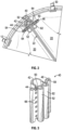
FIG. 1 is a perspective view of a mechanically-expandable prosthetic heart valve, according to one embodiment. -
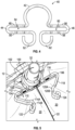
FIG. 2 is a top plan view illustrating a portion of the prosthetic heart valve ofFIG. 1 . -
FIG. 3 is a perspective view of a commissure clamp, according to one embodiment. -
FIG. 4 is a top plan view of the commissure clamp ofFIG. 3 . -
FIG. 5 is a perspective view illustrating a portion of the prosthetic heart valve ofFIG. 1 including another embodiment of a commissure clamp. -
FIG. 6 is a perspective view of another embodiment of a commissure clamp formed from a wire member. -
FIGS. 7-9 illustrate the commissure clamp ofFIG. 6 positioned on an actuator component of a mechanically-expandable prosthetic heart valve. -
FIG. 10 is a rear perspective view of an actuator component. -
FIG. 11 is a front elevation view of the commissure clamp ofFIG.6 positioned on an actuator component. -
FIG. 12 is a top plan view of a portion of a mechanically-expandable prosthetic heart valve illustrating a commissure formed using the commissure clamp ofFIG. 6 . -
FIG. 13 is a cross-sectional top plan view of a portion of a mechanically-expandable prosthetic heart valve illustrating a commissure formed using the commissure clamp ofFIG. 6 , and in which the leaflets are folded to form cuffs. -
FIGS. 14-16 illustrate another embodiment of a commissure clamp. -
FIGS. 17 and 18 illustrate the commissure clamp ofFIG. 14 positioned on an actuator component of a mechanically-expandable prosthetic heart valve. -
FIG. 19 is a rear perspective view of the actuator component ofFIGS. 17 and 18 . -
FIG. 20A is a perspective view of a commissure support element including a collar portion and two members extending from the collar portion to define a leaflet-receiving space, according to one embodiment. -
FIG. 20B is a perspective view of another embodiment of a commissure support element. -
FIG. 21 is a perspective view of an actuator component. -
FIGS. 22 and 23 are perspective views illustrating placement of the commissure support element ofFIG. 20A on the actuator component ofFIG. 21 . -
FIGS. 24A-24D and25 are various views of a commissure formed with the commissure support element ofFIG. 20A on the actuator component ofFIG. 21 , according to one embodiment. -
FIG. 26 is a perspective view of another embodiment of a commissure support element including projections on the inner perimeter of the collar portion. -
FIG. 27 is a top plan view of the commissure support element ofFIG. 26 coupled to an actuator component. -
FIGS. 28 and 29 are perspective views of additional embodiments of the commissure support element ofFIG. 26 . -
FIG. 30 is a perspective view of a commissure support element according to another embodiment. -
FIG. 31 is a side elevation view of a commissure formed with the commissure support element ofFIG. 30 . -
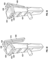
FIG. 32 is a perspective view of another embodiment of a commissure support element coupled to a corresponding actuator component. -
FIG. 33 is a side elevation view of the commissure support element and the actuator component ofFIG. 32 illustrating the coupling portion of the commissure support element. -
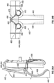
FIG. 34 is a side elevation view of the commissure support element and the actuator component ofFIG. 32 , according to another embodiment. -
FIGS. 35 and36 are top plan views illustrating connection of the commissure support element ofFIG. 32 to the actuator component. -
FIG. 37 is a front elevation view of another embodiment of a commissure support element. -
FIG. 38 is a front elevation view of another embodiment of a commissure support element in which the first and second members extend upwardly from the coupling portion. -
FIG. 39 is a perspective view of the commissure support element ofFIG. 38 coupled to an actuator element. -
FIGS. 40 and 41 are side elevation views schematically illustrating forces developed by leaflets coupled to the commissure support element ofFIG. 38 at various angles. -
FIG. 42 is a perspective view of an assembly including the commissure support element ofFIG. 38 and a commissure plate coupled to an actuator component. -
FIGS. 43 and 44 illustrate another embodiment of a curved commissure support element in which the coupling members are attached to an actuator component and the first and second members extend in a direction toward the outflow end of the prosthetic valve. -
FIG. 45 is a front elevation view of a commissure support element with the first and second members tied together with sutures, according to another embodiment. -
FIG. 46 is a perspective view of a commissure illustrating the first and second members of a commissure support element tied together with sutures, according to another embodiment. -
FIG. 47 is a front elevation view of a commissure support element including notches for retaining sutures, according to another embodiment. -
FIG. 48 is a front elevation view of a commissure support element in which the first and second members include opposing projections, according to another embodiment. -
FIG. 49 is a front elevation view of a commissure support element in which the first and second members include complementary clasp members, according to one embodiment. -
FIG. 50A is a front elevation view of a commissure support element in which the first and second members include flexible leaflet-engaging portions, according to one embodiment. -
FIG. 50B is a cross-sectional top plan view schematically illustrating rotation of the flexible leaflet-engaging portions ofFIG. 50A . -
FIG. 51 is a front elevation view of a commissure support element in which the first and second members include a plurality of opposed projections, according to one embodiment. -
FIG. 52 is a front elevation view of a commissure support element in which the first and second members include opposed projections and clasps. -
FIG. 53 is a front elevation view of a commissure support element in which the first and second members include notches and opposed projections, according to another embodiment. - The present disclosure pertains to prosthetic heart valves including commissure support elements, such as commissure clamps, for clamping the edges or tab portions of two adjacent leaflets together to form a commissure. In certain embodiments, the commissure clamps can comprise, or can be made from, wire form members that are bent or curved to assume the selected shape. In the case of mechanically-expandable prosthetic heart valves, the wire form commissure clamps can be positioned around actuator assemblies or components of the frame. The commissure clamps can be elastic structures, and can clamp the leaflets together, as well as against the actuator component and/or other portions of the frame. Due to the relatively small diameter of the wire members, the commissure clamps can clamp the leaflets together without significantly increasing the overall crimp profile of the valve. In embodiments in which the commissure clamps are elastically deformable, the leaflets and commissure clamps can be assembled together, and then the commissure clamps can be temporarily elastically deformed for positioning on the actuator components of the prosthetic valve frame.
- In certain embodiments the commissure support elements can comprise a coupling portion configured to be coupled to a post, such as an actuator component of a mechanically-expandable valve, and a pair of members extending from the post along the longitudinal axis of the prosthetic valve. The members can be spaced apart from each other, and can define a leaflet-receiving region configured to receive the leaflets of a commissure. The members can be coupled together at a location offset from the coupling portion in the inflow direction or the outflow direction. In certain embodiments, the coupling portion can comprise a collar portion that is disposed around the actuator component. In certain embodiments, the coupling portion comprises a pair of coupling members that can be received in corresponding channels or openings defined in the actuator component. The commissure support elements can be configured to reduce the stresses on the leaflets where the leaflets are attached to the commissure support elements, while also maintaining a low crimp profile of the collapsed prosthetic valve.
-
FIG. 1 illustrates a mechanically-expandableprosthetic heart valve 10, according to one embodiment. Theprosthetic valve 10 can include an annular stent orframe 12, and aleaflet structure 14 situated within and coupled to theframe 12. Theframe 12 can include aninflow end 16 and anoutflow end 18. The leaflet structure can comprise a plurality ofleaflets 20, such as three leaflets arranged to collapse in a tricuspid arrangement similar to the aortic valve, such that the leaflets formcommissures 22 where respectiveoutflow edge portions 24 of the leaflets contact each other. Alternatively, the prosthetic valve can include twoleaflets 20 configured to collapse in a bicuspid arrangement similar to the mitral valve, or more than three leaflets, depending upon the particular application. - The
frame 12 can include a plurality of interconnected lattice struts 26 arranged in a lattice-type pattern and forming a plurality ofapices 28 at theoutflow end 18 of the prosthetic valve. Thestruts 26 can also formsimilar apices 28 at theinflow end 16 of the prosthetic valve. The lattice struts 26 can be pivotably coupled to one another by hinges 30 located where the struts overlap each other, and also at theapices 28. The hinges 30 can allow thestruts 26 to pivot relative to one another as theframe 12 is expanded or contracted, such as during assembly, preparation, or implantation of theprosthetic valve 10. The hinges 30 can comprise rivets or pins that extend through apertures formed in thestruts 26 at the locations where the struts overlap each other. Additional details regarding theframe 12 and devices and techniques for radially expanding and collapsing the frame can be found inU.S. Publication No. 2018/0153689 , which is incorporated herein by reference. - As illustrated in
FIG. 1 , theframe 12 can comprise a plurality ofactuator components 32 that can also function as release-and-locking units (also referred to as locking assemblies) configured to radially expand and contract the frame. In the illustrated configuration, theframe 12 can comprise threeactuator components 32 configured as posts and coupled to theframe 12 at circumferentially spaced locations, although the frame may include more or fewer actuator components depending upon the particular application. Each of theactuator components 32 generally can comprise an inner member 34, such as an inner tubular member, and anouter member 36, such as an outer tubular member concentrically disposed about the inner member 34. The inner members 34 and theouter members 36 can be moveable longitudinally relative to each other in a telescoping manner to radially expand and contract theframe 12, as further described inU.S. Publication No. 2018/0153689 incorporated by reference above. - In the illustrated configuration, the inner members 34 can have distal end portions 38 coupled to the
inflow end 16 of the frame 12 (e.g., with a coupling element such as a pin member). In the illustrated embodiment, each of the inner members 34 are coupled to the frame atrespective apices 28 at theinflow end 16 of the frame. Theouter members 36 can be coupled toapices 28 at theoutflow end 18 of theframe 12 at, for example, a mid-portion of the outer member, as shown inFIG. 1 , or at a proximal end portion of the outer member, as desired. - The inner member 34 and the
outer member 36 can telescope relative to each other between a fully contracted state (corresponding to a fully radially expanded state of the prosthetic valve) and a fully extended state (corresponding to a fully radially compressed state of the prosthetic valve). In the fully extended state, the inner member 34 is fully extended from theouter member 36. In this manner, theactuator components 32 allow the prosthetic valve to be fully expanded or partially expanded to different diameters and retain the prosthetic valve in the partially or fully expanded state. - In alternative embodiments, the
actuator components 32 can be screw actuators configured to radially expand and compress theframe 12 by rotation of one of the components of the actuators. For example, the inner members 34 can be configured as screws having external threads that engage internal threads of corresponding outer components. Further details regarding screw actuators are disclosed inU.S. Publication No. 2018/0153689 . - Referring to
FIG. 1 , theprosthetic valve 10 can include a plurality of commissure support elements configured as commissure clasps or clamps 40. In the illustrated configuration, the prosthetic valve includes acommissure clamp 40 positioned at eachcommissure 22 and configured to grip theleaflets 20 of the commissure at a location spaced radially inwardly of theframe 12. -
FIGS. 2-4 illustrate arepresentative commissure clamp 40 in greater detail. Thecommissure clamp 40 can include a main portion orcoupling portion 42 configured as a cylindrically-shaped recessed portion or collar, and first andsecond clamp members coupling portion 40. As best shown inFIG. 4 , thefirst clamp member 44 can include afirst portion 48 extending away from thecoupling portion 42. Theclamp member 44 can be curved (e.g., by 180°) such that asecond portion 50 extends from thefirst portion 48 parallel to and spaced apart from thefirst portion 48 in a direction back toward thecoupling portion 42. Athird portion 52 can extend from thesecond portion 50, and can curve around (e.g., by 180°) such that an end portion of thethird portion 52 is adjacent a mid-portion of thesecond portion 50. The first andsecond portions space 54 therebetween. Thesecond clamp member 46 can be symmetrical with thefirst member 44, and can include first andsecond portions space 60 opposite the leaflet-receivingspace 54 and in communication with the leaflet-receivingspace 54. A curvedthird portion 62 can extend from thesecond portion 58 similar to theportion 52 of thefirst member 44. As shown inFIG. 3 , the inward-facing surfaces of thesecond portions openings 66. - Referring again to
FIG. 1 , the commissure clamps 40 can be situated on theactuator components 32 such that theouter members 36 are received in thecoupling portions 42 of the commissure clamps, and such that the leaflet-receivingspaces coupling portion 42 can be sized and shaped to frictionally engage and/or clamp onto the outer surface of theouter member 36 of theactuator component 32 so as to secure thecommissure clamp 40 to theouter member 36. In lieu of or in addition to frictional or clamping forces, thecoupling portion 42 can be welded to theouter member 36, or secured to theouter member 36 using an adhesive, sutures and/or mechanical fasteners. - As shown in
FIGS. 1 and2 ,commissure tabs 64 of theleaflets 20 can be inserted into the leaflet-receivingspaces commissure tab 64 of oneleaflet 20 can be folded around thethird portion 52 and inserted into the leaflet-receivingspace 54 such that a portion of the commissure tab extends radially between thethird portions members space 54 extends circumferentially along the frame. Thecommissure tab 64 of theother leaflet 20 can be folded and inserted into the leaflet-receivingspace 60 in a similar manner. In certain configurations, theleaflets 20 can be sutured to the commissure clamps 40 through the openings 66 (FIG. 3 ). - The curved
third portions leaflets 20 of eachcommissure 22 at a location that is offset radially inwardly from the strut members of theframe 12. In this manner, theleaflets 20 can articulate about axes offset from theframe 12 as they coapt and move away from each other during valve operation. For example, in the illustrated configuration theleaflets 20 can articulate about thethird portions second clamp members portions members -
FIG. 5 illustrates another embodiment of acommissure clamp 100 that can be used in combination with theprosthetic valve 10 ofFIG. 1 . InFIG. 5 , thecommissure clamp 100 is shown in an open configuration prior to crimping or closing of the clamping arms to clamp theleaflets 20. Thecommissure clamp 100 can include a main portion configured as acoupling portion 102 defining a cylindrically-shaped recess that is shaped to be placed around an actuator component. The commissure clamp can further comprise first andsecond clamp members coupling portion 102. Thefirst clamp member 104 can include afirst portion 108 extending outwardly from thecoupling portion 102, and asecond portion 110 extending at an angle to thefirst portion 108 such that the first andsecond portions second portion 110 can include one or more curved portions configured as leaflet-engaging portions 114. In the illustrated embodiment, thefirst clamp member 104 includes two leaflet-engagingportions portion 114B is offset from the leaflet-engagingportion 114A in a direction radially inward toward the center of the prosthetic valve in the position illustrated inFIG. 5 . - The
second clamp member 106 can be configured similar to thefirst clamp member 104, with afirst portion 116 extending from thecoupling portion 102 in the opposite direction from thefirst portion 108 of thefirst clamp member 104. Thesecond clamp member 106 can further include asecond portion 118 extending at an angle to thefirst portion 116. Thesecond portion 118 can include two curved leaflet-engagingportions portions first member 104. In the configuration illustrated inFIG. 5 , the leaflet-engagingportion 120B can be offset from the leaflet-engagingportion 120A in a direction radially inward toward the center of the prosthetic valve, similar to the leaflet-engagingportion 114B. - The
second portions second clamp members second portions respective clamp members FIG. 5 to a closed position wherein theportion 110 is parallel to theportion 108 and theportion 118 is parallel to theportion 116, similar to the embodiment ofFIG. 4 . In the closed configuration, the leaflet-engagingportion 114A can clamp theleaflet 20 on the left side ofFIG. 5 against theportion 108, and the leaflet-engagingportion 120A can clamp theleaflet 20 on the right side ofFIG. 5 against theportion 116. - Meanwhile, the
leaflets 20 can also be clamped or pressed together between the leaflet-engagingportions curved end portions respective members leaflets 20 can articulate about axes adjacent theend portions frame 12. - In other embodiments, the
clamp members FIG. 5 , and the leaflet-engagingportions leaflets 20 at a first location, and the leaflet-engagingportions leaflets 20 can articulate about axes adjacent the leaflet-engagingportions frame 12. - Additionally, in certain configurations, clamping the leaflets at multiple locations, such as between the leaflet-engaging
portion 114A and theportion 108 on the left side ofFIG. 5 , between the leaflet-engagingportion 120A and theportion 116 on the right side ofFIG. 5 , between theportions end portions clamp 100 against the leaflets. In some embodiments, the leaflet-engagingportions U.S. Application No. 15/978,459, filed on May 14, 2018 -
FIG. 6 illustrates another embodiment of a commissure clamp 200 (also referred to as a commissure support element) comprising a relatively small diameter, wire-form body ormember 202. In certain embodiments, themember 202 can be a thin, flexible, wire or rod with a single or multiple layers of the same or different materials, and can be bent or formed into a variety of shapes. For example, in the configuration illustrated inFIG. 6 , thewire member 202 is bent or formed such that the clamp comprises a first ring, coupling portion, orcollar portion 204, and a second coupling portion orcollar portion 206. The first andsecond collar portions wire member 202, and can extend between and interconnect thecollar portions first collar portion 204 can at least partially enclose a space oropening 212, and thesecond collar portion 206 can at least partially enclose a space oropening 214. - In the illustrated embodiment, the
first collar portion 204 can comprise a relatively straight rear or radiallyoutward portion 216, and thesecond collar portion 206 can comprise a corresponding straightrear portion 218. Therear portion 216 can be coupled to theclamp members side portions collar portion 204. Theportions rear portion 216 away from theclamp members second collar portion 206 can compriseportions portions - The
wire body 202 can be formed from any of a variety of elastically deformable materials and/or plastically deformable materials such as metals including nitinol, stainless steel, cobalt-chromium, etc., or polymeric materials. Exemplary polymeric materials can include ultra-high-molecular-weight polyethylene (UHMWPE) (e.g., Dyneema®), high-molecular-weight polyethylene (HMWPE), or polyether ether ketone (PEEK), polytetrafluoroethylene (PTFE), expanded polytetrafluoroethylene (ePTFE), ethylene tetrafluoroethylene (ETFE), nylon, polyethylene, polyether block amide (e.g., Pebax), and/or combinations of any of the above. In some embodiments, the wire body can comprise multiple layers such as, for example, an inner metal layer and one or more polymeric outer layers. - In particular embodiments, a clamp 200 (and the other embodiments of clamps disclosed herein) can be formed by bending a piece of wire (e.g., a straight piece of wire) into the shape shown in
FIG. 6 and securing the free ends of the wire together, such as by welding. In alternative embodiments, other techniques and/or methods can be used to form a clamp 200 (and the other embodiments of clamps disclosed herein). For example, a clamp can be formed by molding (e.g., injection molding), machining (e.g., laser cutting), or 3D printing. -
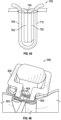
FIGS. 7-10 are various views illustrating thecommissure clamp 200 situated on anactuator component 228. Theactuator component 228 can be, for example, the outer member of an actuator of a mechanically-expandable prosthetic heart valve, similar to theouter members 36 of theactuator components 32 of theprosthetic valve 10 ofFIG. 1 . In the illustrated embodiment, theactuator component 228 can have a rectangular cross-section, although in other embodiments the actuator component may have a round cross-section, or a cross-section having any other selected shape. Desirably, thecollar portions longitudinal axis 237 of the actuator component. Thecommissure clamp 200 can be positioned on theactuator component 228 such that the clampingmembers surface 230 of theactuator component 228, and therear portions FIG. 8 ) of the actuator component. - Referring to
FIG. 10 , in certain embodiments theactuator components 228 can comprise grooves orchannels portions FIG. 9 , in certain embodiments theportions longitudinal axis 237 of theactuator component 228. For example,FIG. 9 illustrates theportions inward surface 230 of theactuator component 228 can define an axially-extending groove orchannel 238. - In certain embodiments, the leaflets of a commissure can be assembled together with the commissure clamps prior to positioning the commissure clamps in a valve frame. For example, in some embodiments the leaflets, or tab portions thereof, can be folded around and optionally attached (e.g., sutured) to the
clamp members wire member 202 comprises a flexible or elastically deformable material, the clampingmembers members FIG. 11 . Thus, the assembled commissure clamp and leaflets can be coupled to the frame by opening theclamp members FIG. 11 , and situating thecommissure clamp 200 around theactuator component 228. Thecommissure clamp 200 is shown positioned around theactuator component 228 inFIG. 11 without the leaflets for purposes of illustration. - For example,
FIG. 12 illustrates a portion of an assembledcommissure 264 in which atab portion 242 of aleaflet 240 is folded around the clampingmember 208, and clamped between the clampingmember 208 and theactuator component 228. On the opposite side, atab portion 246 of aleaflet 244 is folded around the clampingmember 210 and clamped against theactuator component member 228 by the clampingmember 210. In certain embodiments, the non-deformed or natural size of thecollar portions actuator component 228 such that the collar portions are in an expanded state when placed around the actuator component, thereby causing themembers leaflets members actuator component 228 and do not extend into the lumen of the prosthetic valve, thecommissure clamp 200 can provide a relatively low-profile leaflet attachment solution that does not significantly increase the crimp profile of the valve, and which is relatively easy to assemble. In other embodiments, thecommissure clamp 200 can be placed around theactuator component 228 first, followed by insertion of theleaflets - In certain embodiments, the tab portions of the leaflets can be folded around or beside the clamping members of the commissure clamp to stabilize the commissure and prevent rotation of the leaflets during valve operation. For example,
FIG. 13 illustrates an embodiment in which a reinforcing member configured as afabric strip 248 is wrapped around the clampingmember 208 and forms aloop 250. Thefabric strip 248 can extend from theloop 250, and can be positioned on or around the radially inward-facing surface of theleaflet tab 242. Theleaflet tab 242 can be folded on itself to form acuff 252 having afirst layer 260 and asecond layer 262. More particularly, thecuff 252 can be folded about a fold line extending into the plane of the page inFIG. 13 such that a folded edge 254 of thecuff 252 can be oriented radially inwardly generally toward the center of the prosthetic valve, and the open side orfore edge 256 of the cuff can be oriented radially outward toward theactuator component 228. The construction can be sutured together withsuture 258. Thesuture 258 can secure thefabric loop 250 around the clampingmember 208. Thesuture 258 can also extend through bothlayers cuff 252, and both corresponding layers of thefabric strip 248 disposed around thecuff 252. In this manner, thecuff 252, and more particularly thefabric strip 248 and thelayer 262 of the leaflet tab, can abut or bear against theactuator component member 228, and can resist rotation and/or sliding of theleaflet 240 around the clampingmember 208 as the leaflet opens and closes during valve operation. Thefore edge 256 of the cuff can be open, as illustrated inFIG. 13 , or may be closed, depending upon the particular application. A similar construction can be formed around the clampingmember 210 with a reinforcing member, suture, and thetab portion 246 of theleaflet 244. -
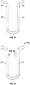
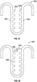
FIGS. 14-16 illustrate another embodiment of acommissure clamp 300. Thecommissure clamp 300 can be formed from a relatively thin, wire-form body ormember 302, similar to the embodiment ofFIG. 6 . Thewire member 302 can be bent or formed such that theclamp 300 comprises a first coupling portion orcollar portion 304, a second coupling portion orcollar portion 306. First and second clamping members, or connecting members, 308 and 310 can extend between and interconnect thecollar portions Portions first collar portion 304 can be curved, and angled downwardly toward thesecond collar portion 306. In the illustrated embodiment,portions second collar portion 306 can be curved, and can be angled upwardly toward thefirst collar portion 304. With reference toFIG. 15 , at the rear of thecollar portion 304 opposite the clampingmembers wire member 302 can be bent to form aloop 320. Theloop 320 can comprise aclosed end portion 322 oriented upwardly in the figure, and anopen end portion 324 facing downwardly toward thesecond collar portion 306. Thewire member 302 can be bent to form asimilar loop 326 at the rear of thesecond collar portion 306 oriented in the opposite direction from theloop 320. -
FIGS. 17 and 18 illustrate thecommissure clamp 300 positioned on anactuator component 328 of, for example, a mechanically-expandable valve similar to thevalve 10 ofFIG. 1 . Referring toFIGS. 17 and 19 , in certain embodiments theactuator component 328 can comprise a channel or groove 330 in its radially-inward surface 332, and/or agroove 334 in its radially-outward surface 336. Thegrooves actuator component 328. Referring toFIG. 19 , the radially-outward surface 336 can also comprise channels orgrooves groove 334. When thecommissure clamp 300 is disposed on theactuator component 328, theloops groove 334. Theportions first collar portion 304 can be received in thegrooves 338, and theportions collar portion 306 can be received in thegrooves 340. The grooves on both sides of theactuator component 328 help align the commissure clamp at its proper location on the actuator component during assembly, assist in retaining the commissure clamp in place on the actuator component, and minimize the extent that portions of the clamp extend from the actuator component in a radial direction so as to further minimize the crimped profile of the prosthetic valve. - The clamping
members actuator component 228 and clamp leaflets against the actuator component, similar to the embodiments described above. -
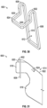
FIG. 20A illustrates another embodiment of acommissure support element 400 comprising a unitary or wire-form body 402. Thecommissure support element 400 can comprise an annular or curved coupling portion orcollar portion 404 at least partially enclosing a first area orcoupling region 406. Thecommissure support element 400 can further comprise first andsecond members collar portion 404 at an angle to the plane of the collar portion (e.g., 90°). More particularly, thefirst member 408 can comprise afirst end portion 412 coupled to thecollar portion 404 and adistal end portion 414. Thesecond member 410 can comprise afirst end portion 416 coupled to the collar portion opposite thefirst end portion 412 of the first member, and asecond end portion 418. Thesecond end portions member 420 extending therebetween. Themember 420 can be straight or curved. Members orportions 434 and 436 (FIG. 23 ) can space or offset the first andsecond members FIGS. 22 and 23 . - Referring again to
FIG. 20A , the first andsecond members window 422 between them that extends between thecollar portion 404 and themember 420. The wire-form body 402 can have a rectangular cross-section, as shown inFIG. 20A , or may be round or cylindrical, as shown inFIG. 20B . Themember 420 connecting the first andsecond members FIG. 20B . - In certain embodiments, the
commissure support element 400 can be configured for attachment to a post, such as an actuator component of a mechanically-expandable prosthetic heart valve configured according to any of the embodiments described herein.FIG. 21 illustrates a representative example of anactuator component 424, which may be configured according to any of the actuator components described herein, and further configured to receive thecommissure support element 400. Theactuator component 424 can define a groove, slot, orrecess 426 at theoutflow end 428 of the component on a radiallyoutward surface 430 of the component. The cross-section of the actuator component 424 (or of the outer housing thereof) can have a shape or aspect ratio corresponding to the shape of the coupling region 406 (e.g., rectangular or square, with or without rounded corners, or curved or cylindrical, etc.). -
FIGS. 22 and 23 illustrate placement of thecommissure support element 400 on theactuator component 424. Referring toFIG. 22 , a radially outward (relative to the frame of which the actuator component is a part) portion ormember 432 of thecollar portion 404 can be located or situated in therecess 426. Theelement 400 can then be rotated such that the remaining portions of thecollar portion 404 are brought into engagement with theactuator component 424 with the first andsecond members recess 426 can help to retain the commissure support element in place on the actuator component. In certain embodiments, thecollar portion 404 and theactuator component 424 can be configured such that the collar portion snaps into place or is held in the use position to aid in retaining the commissure support element on the actuator component. When thecommissure support element 400 is coupled to theactuator component 424, the first andsecond members - In certain embodiments, the
commissure support element 400 can be formed or bent from a wire member, and/or can be cut (e.g., laser cut) from a plate or sheet. Thecommissure support element 400 can comprise a single or multiple layers of the same or different materials (e.g., metals, polymers, etc.), as described above. -
FIGS. 24A-24D and25 illustrate twoleaflets commissure support element 400 to form acommissure 442. Each of the leaflets can comprise at least one leaflet tab or commissure tab on each side, which can be inserted through the leaflet-receiving window 422 (FIG. 20A ) of the commissure support element and secured to the commissure support element, to theactuator component 424, and/or to the commissure tab of the adjacent leaflet. For example, referring toFIG. 24A , theleaflet 440 can comprise a commissure tab 450 (e.g., a lower tab and/or an upper tab) inserted through the leaflet-receivingwindow 422, and folded around thesecond member 410. A portion of thecommissure tab 450 can contact or lie against the radially-inward surface 446 of the actuator element. A portion of thecommissure tab 450 can be folded to form a fold orcuff 448. Referring toFIG. 25 , a leaflet tab 444 (e.g., a lower tab and/or an upper tab) of theleaflet 438 can be inserted through the leaflet-receivingwindow 422 and folded around thefirst member 408 to form a cuff in a similar manner. In certain embodiments, the leaflet tabs can space thesecond end portions 414 and 418 (FIG. 20A ) of the first andsecond members actuator component 424. - In certain embodiments, the
leaflet tabs window 422 and theactuator component 424, such as by sutures 452 (FIG. 25 ). The leaflets can further be attached to the first andsecond members 408, 410 (e.g., to the second end portions of the members) bysutures 454, although in other embodiments thesutures 454 may be omitted. -
FIG. 24B illustrates a top plan view of thecommissure assembly 442. The leaflet tab and/ortabs 444 of theleaflet 438 can be wrapped or folded around theaxial member 408 such that there are threelayers FIG. 24C ). Thetab 450 of theleaflet 440 can be wrapped or can extend around theaxial member 410. In certain embodiments, upper tabs of the leaflets can be folded downwardly at a location radially outward of themembers stitch protector member 456 can be disposed around theaxial member 408 between the axial member and the layers of theleaflet tab 444. A first attachment line, stitch, line, orsuture line 460 can secure thelayers FIG. 24B ). Asecond suture line 462 can extend through the stitch protector member, through at least the leaflet tab layers 458B and 458C, and through awedge member 464 disposed radially outwardly of thecommissure support element 400. Thewedge member 464 can be disposed between theleaflet tabs leaflet tab 450 can be folded similarly, with astitch protector layer 466 disposed around theaxial member 410, asuture line 468 extending through thelayers axial member 410, and asuture line 470 extending through thesuture protection member 466, theleaflet tab 450, and thewedge member 464.FIGS. 24C and 24D provide a perspective view and a rear elevation view (e.g., looking radially inwardly) of thecommissure 442. - In certain embodiments, the
commissure support element 400 can provide certain advantages, such as ease of manufacturing, ease of attachment to the actuator component, and/or ease of assembly of the commissure. -
FIG. 26 illustrates another embodiment of acommissure support element 500 comprising a unitary or wire-form body similar to theelement 400 ofFIG. 20A . The commissure support element can include a curved coupling portion orcollar portion 502, and a leaflet-receivingwindow 504 defined by first andsecond members collar portion 502, and across member 510 extending between the first and second members at the opposite end of thewindow 504 from thecollar portion 502. - The inner perimeter of the
collar portion 502 can comprise a first inwardly-extending projection orprotrusion 512 and a second inwardly-extending projection orprotrusion 514 on the opposite side of the collar from the first projection and oriented generally toward the first projection. Referring toFIG. 27 , thecollar portion 502 of thecommissure attachment element 500 can be configured for attachment to a post oractuator component 516 of a mechanically-expandable prosthetic heart valve adapted to receive the collar portion. For example, theactuator component 516 can comprise a notch, slot, orrecess 518 shaped to correspond to theprojection 512 and a notch, slot, orrecess 520 shaped to correspond to theprojection 514. Theprojections recesses arrow 521. Thus, theprojections recesses member 522 of thecollar portion 502, allowing therear member 522 to be made thinner. This, in turn, can decrease the crimped diameter or profile of the prosthetic heart valve. The side portions of the collar member from which the projections extend can also be thicker to accommodate the forces. - In
FIG. 26 , the first andsecond members cross member 510. However, in certain embodiments thecross member 510 can be omitted, as in the embodiment ofFIG. 27 . -
FIG. 28 illustrates another configuration of thecommissure support element 500 in which the first andsecond members cross member 510 include a plurality of openings 524 (e.g., at the inflow and outflow ends of themembers 506 and 508). Suture(s) can be inserted or threaded through the openings to attach the commissure support element to an actuator component, and/or to attach leaflets to the commissure support element. For example, in certain embodiments sutures can be threaded or looped between theupper openings 524 such that the sutures extend above the leaflet tabs to retain the leaflets in position, and/or to draw the upper portions of themembers -
FIG. 29 illustrates another embodiment of thecommissure support element 500 in which the support element comprises a planar member orplate member 526 extending from thecollar portion 502 perpendicular, or substantially perpendicular, to the collar portion. Theplate member 526 can comprise a plurality ofopenings 528. In the illustrated embodiment, theopenings 528 are arranged in two vertical columns of four openings, although in other embodiments theplate member 526 can have any number of openings arranged in any arrangement including a single opening or no openings. The leaflet tabs of a commissure can be wrapped around theplate member 526. In certain embodiments, the leaflet tabs can be secured with sutures through theopenings 528. In certain embodiments, sutures can be inserted through theopenings 528 to attach the commissure support member and/or the commissure to an actuator component. In other embodiments, the first and second members ofFIG. 28 can comprise openings arranged in columns similar toFIG. 29 . -
FIG. 30 illustrates another embodiment of acommissure support element 600 configured similarly to thesupport element 400 ofFIG. 20A . Thecommissure support element 600 comprises U-shapedcurved member 602 extending between thecollar portion 604 and the firstaxial member 606. The support element further comprises a similarcurved member 608 extending between thecollar portion 604 and the secondaxial member 610. Thecurved members collar portion 604, which can lengthen the first andsecond members window 612. The apices of thecurved members members second members commissure support element 600 can be made from a wire-form member, and/or can be laser cut from a sheet of material and bent, curved, or folded into the specified shape, as described above. - As noted above, the
curved members second members window 612. In certain embodiments, the longer leaflet-receiving window can reduce stress on the leaflets and the corresponding risk of tearing during valve operation. For example,FIG. 31 illustrates a side elevation view of acommissure 614 includingleaflets 616 received in thecommissure support element 600. The actuator component and frame of the prosthetic valve are omitted for clarity. The longer leaflet-receiving window 612 (FIG. 30 ) can allow the window to accommodateleaflet tabs 618 which includeadditional tabs 620 disposed along theoutflow edge 622 of theleaflets 616. In the illustrated configuration, theoutflow edge 622 can slope downwardly in the direction of the inflow end of the valve. During diastole, theleaflets 616 can tend to extend radially inwardly to coapt with each other, which can exert corresponding stresses, represented schematically byarrows 624, on the leaflets at the location of attachment to thecommissure support element 600. This can also result in the application of force to the commissure support element. Theangled outflow edge 622 of the leaflets can result in a non-uniform stress distribution along the attachment of the leaflets to the leaflet-receivingwindow 612. Theadditional leaflet tabs 620, and/or lengthenedleaflet tabs 618, together with the longer leaflet-receivingwindow 612, can result in a more even stress distribution along the leaflet tabs at the location(s) of attachment to the commissure support element. Including theadditional leaflet tabs 620 can also result in the development of maximum stresses within the bodies of the leaflets, rather than at the outflow edges, reducing the risk of tearing. - Although the configuration illustrated in
FIG. 30 shows thecurved members side members collar portion 604 resulting in a spacing equal to or substantially equal to the length of the major axis of thecollar portion 604, the curved members may also be positioned closer together. For example, thecollar portion 602 can be configured similarly to thecollar portion 404 ofFIG. 20A , and the curved members can extend from the location of attachment of themembers members -
FIGS. 32 and 33 illustrate another embodiment of acommissure support element 700 configured as a unitary wire-form body 702 including a coupling portion 704 (FIG. 33 ) and a leaflet-receiving window 706 (FIG. 32 ) defined by axially-extending first andsecond members FIG. 33 , thecoupling portion 704 can comprise a pair ofcoupling members coupling member 712 can be coupled to the firstaxial member 708 by a curved portion ormember 716, and thecoupling member 714 can be coupled to the secondaxial member 710 by a curved portion ormember 718. In certain embodiments, thecoupling portions axial members coupling members actuator 722 is a part, although other configurations are possible. In the illustrated embodiment, the angular or circumferential spacing between thecoupling members axial members members curved members - The first and second
axial members FIG. 32 ). Themember 720 can be curved or straight. Themembers window 706, which can be open at the top. Referring toFIG. 33 , in certain embodiments one of thecoupling members FIG. 33 thecoupling member 712 is longer than thecoupling member 714, although the opposite configuration can also be implemented. Thecoupling members FIG. 34 . - Referring again to
FIG. 32 , thecommissure support element 700 can be received by or coupled to a post oractuator component 722 of a mechanically-expandable prosthetic heart valve, which can be configured similarly to any of the actuator components described herein. Theactuator component 722 can comprise a pair of tubular openings orchannels coupling members channels outflow end portion 728 of the actuator component, although the channels may be located anywhere around the perimeter of the actuator component and at any location along its length. Thecommissure support element 700 can be configured such that when coupled to theactuator component 722, thecurved members upper surface 730 of the actuator component, although the support element may also be disposed elsewhere along the length of the actuator component between the inflow and outflow end portions of the actuator component. - In certain embodiments, the axial length of the leaflet-receiving
window 706 can correspond to the length of the leaflet tabs of the leaflets of the commissure in order to restrain axial movement of the leaflet tabs. The length of thecurved members axial members inward surface 732 of the actuator component. The distance between theaxial members surface 732 of the actuator component can be selected to allow the leaflet tabs to extend between themembers surface 732, and to enable clamping of the leaflet tabs by themembers surface 732. The spacing between themembers - The
commissure support element 700 can be formed from a wire-form body as described above, or can be laser cut from a plate or sheet and bent, folded, and/or formed into the specified shape. Thecommissure support element 700 can comprise a metal material, a polymeric material, and/or combinations or layers thereof. -
FIGS. 35 and36 illustrate the steps of coupling thecommissure support member 700 to theactuator component 722, according to one embodiment. InFIG. 35 the coupling member 712 (FIG. 33 ) can be inserted into the correspondingchannel 724 with the commissure support element rotated such that thecoupling member 714 is disposed radially inwardly of theactuator component 722. In embodiments where thecoupling member 712 is longer than thecoupling member 714, thecoupling member 712 may be inserted into the actuator component first. With thecoupling member 712 at least partially advanced into thechannel 724, the commissure support element can be rotated about thecoupling member 712 to align thecoupling member 714 with thechannel 726. The commissure support element can then be advanced in the direction of the inflow end of the prosthetic valve such that thecoupling members channels -
FIG. 37 illustrates another embodiment of acommissure support element 700 in which thecoupling members protrusions protrusions actuator component 722 in order to retain the commissure support element in place on the actuator component. - In other embodiments, the first and second
axial members window 706 is V-shaped. In yet other embodiments, the first and secondaxial members axial members - In certain embodiments, the commissure support elements described herein can be coupled to the actuator components such that the first and second axial members extend from the coupling portion upwardly in the direction of the inflow end of the prosthetic valve. For example,
FIG. 38 illustrates another embodiment of thecommissure support element 700 configured for attachment to an actuator element with themember 720 located at the outflow end of the element, andFIG. 39 shows theelement 700 coupled to a modified embodiment of theactuator component 722. More particularly, thechannels inflow end 736 and theoutflow end 728 of the actuator component, such as offset from theoutflow surface 730 in a direction toward thehinge pin member 738, or located between thepin member 738 and thesurface 730. When the commissure support element is inserted into thechannels curved members axial members - Referring to
FIGS. 40 and 41 , in certain embodiments the angle of the first andsecond members actuator component 722 can be varied. For example, referring toFIG. 40 , the first andsecond members actuator component 722. Referring toFIG. 41 , in certain embodiments the first andsecond members actuator component 722 and radially inwardly toward the central axis of the prosthetic valve (FIG. 1 ). In certain embodiments, where the first and secondaxial members curved members leaflets 746 and thecommissure support element 700 during valve operation, and particularly during diastole, as indicated schematically inFIGS. 40 and 41 . -
FIG. 42 illustrates another embodiment in which a commissure member orplate 740 is coupled to theactuator component 722. Thecommissure plate 740 can comprise a portion orflange 742 comprising a plurality ofopenings 744. In certain embodiments, thecommissure plate 740 can comprise a similarly configured flange on both sides of the actuator element, or on only one side. In certain embodiments thecommissure plate 740 can be sutured to theactuator component 722 by sutures extending through theopenings 744. In certain embodiments, thecommissure plate 740 can include thechannels commissure plate 740 can be integrally formed with thecommissure support element 700, or with theactuator component 722. The leaflets of the commissure can also be sutured to thecommissure plate 740 through theopenings 744. -
FIGS. 43 and 44 illustrate another embodiment of thecommissure support element 700 in which thecoupling members actuator component 722 and extend in a direction toward the inflow end of the prosthetic valve, while the first andsecond members axial members - The commissure support elements described herein can also include any of a variety of features configured to enable the commissure support elements to engage the leaflets of the commissure. For example,
FIG. 45 illustrates acommissure support element 700 comprisingsuture 748 wrapped around the outflow ends of the first and secondaxial members leaflets 750 to press the members against theleaflets 750.FIG. 47 illustrates another configuration of the commissure supportelement comprising notches 752 in theaxial members sutures 748. -
FIG. 46 illustrates acommissure support element 800 configured similarly to thesupport element 400 comprisingsutures 802 wrapped aroundmembers collar portion 808 to the axial members. -
FIG. 48 illustrates another embodiment of acommissure support element 900 configured similarly to thesupport element 700, wherein the first and secondaxial members protrusions FIG. 45 ). -
FIG. 49 illustrates another embodiment of acommissure support member 1000 configured similarly to thesupport element 700, and in which the first and secondaxial members complementary clasp members clasp members axial members clasp members axial members -
FIG. 50A illustrates another embodiment of acommissure support element 1100 configured similarly to thesupport element 700, wherein the first and secondaxial members flexible tab portions tab portions FIG. 50B is a schematic cross-sectional view of the first and secondaxial members flexible tab portions flexible tab portions flexible tab portions axial members -
FIG. 51 illustrates another embodiment of acommissure support element 1200 configured similarly to thesupport element 700, wherein the first and secondaxial members tabs 1206 on the inner aspect of the members and arranged in an opposing manner. Theprojections 1206 can be configured to frictionally engage leaflets inserted between the axial members. - The features described above may be combined in any of various combinations. In one non-limiting example,
FIG. 52 illustrates an embodiment of acommissure support element 1300 comprisingclasp elements clasps FIG. 49 in combination withprojections 1306 similar to theprojections 1206 ofFIG. 51 .FIG. 53 illustrates another embodiment in which thecommissure support element 1400 comprisessuture retaining notches 1402 for retaining sutures andprotrusions 1404 configured to maintain a minimum spacing between theaxial members - As noted above, any of the commissure support elements disclosed herein can be formed by bending a piece of wire (e.g., a straight piece of wire) into the specified shape and securing the free ends of the wire together, such as by welding. The commissure support elements can also be formed using other techniques including, for example, molding (e.g., injection molding), machining (e.g., laser cutting), and/or 3D printing, and bending or folding the elements into the specified shape as needed.
- Although the commissure support elements disclosed herein have been described as being mounted on an actuator component of a prosthetic valve, any of the commissure support elements disclosed herein can be mounted on other portions of a prosthetic valve. For example, a frame of a prosthetic valve can have axially extending posts that are separate from the actuator components for mounting the commissure support elements. In one specific embodiment, a frame can have a plurality of posts corresponding to the number of commissures (e.g., three posts for three commissures), with each post being mounted to the inner surface of the frame (e.g., to selected
struts 26 of the frame) between twoadjacent actuator components 32. - Further, the commissure support elements described herein may also be used with prosthetic heart valves that do not have actuators, such as self-expandable prosthetic heart valves or plastically-expandable prosthetic heart valves (e.g., such as those that are expanded to their functional size by inflating a balloon). Examples of self-expandable prosthetic heart valves can be found in
U.S. Patent No. 8,652,202 ,U.S. Patent No. 9,155,619 U.S. Publication No. 2014/0343670 , which are incorporated herein by reference. Examples of plastically-expandable prosthetic heart valves can be found inU.S. Patent No. 9,393,110 U.S. Publication No. 2018/0028310 , which are incorporated herein by reference. - For purposes of this description, certain aspects, advantages, and novel features of the embodiments of this disclosure are described herein. The disclosed methods, apparatus, and systems should not be construed as being limiting in any way. Instead, the present disclosure is directed toward all novel and nonobvious features and aspects of the various disclosed embodiments, alone and in various combinations and sub-combinations with one another. The methods, apparatus, and systems are not limited to any specific aspect or feature or combination thereof, nor do the disclosed embodiments require that any one or more specific advantages be present or problems be solved.
- Although the operations of some of the disclosed embodiments are described in a particular, sequential order for convenient presentation, it should be understood that this manner of description encompasses rearrangement, unless a particular ordering is required by specific language set forth below. For example, operations described sequentially may in some cases be rearranged or performed concurrently. Moreover, for the sake of simplicity, the attached figures may not show the various ways in which the disclosed methods can be used in conjunction with other methods. Additionally, the description sometimes uses terms like "provide" or "achieve" to describe the disclosed methods. These terms are high-level abstractions of the actual operations that are performed. The actual operations that correspond to these terms may vary depending on the particular implementation and are readily discernible by one of ordinary skill in the art.
- As used in this application and in the claims, the singular forms "a," "an," and "the" include the plural forms unless the context clearly dictates otherwise. Additionally, the term "includes" means "comprises." Further, the terms "coupled" and "associated" generally mean electrically, electromagnetically, and/or physically (e.g., mechanically or chemically) coupled or linked and does not exclude the presence of intermediate elements between the coupled or associated items absent specific contrary language.
- In the context of the present application, the terms "lower" and "upper" are used interchangeably with the terms "inflow" and "outflow", respectively. Thus, for example, the lower end of a prosthetic valve is its inflow end and the upper end of the prosthetic valve is its outflow end.
- As used herein, the term "proximal" refers to a position, direction, or portion of a device that is closer to the user and further away from the implantation site. As used herein, the term "distal" refers to a position, direction, or portion of a device that is further away from the user and closer to the implantation site. Thus, for example, proximal motion of a device is motion of the device toward the user, while distal motion of the device is motion of the device away from the user. The terms "longitudinal" and "axial" refer to an axis extending in the proximal and distal directions, unless otherwise expressly defined.
- As used herein, the terms "integrally formed" and "unitary construction" refer to a construction that does not include any welds, fasteners, or other means for securing separately formed pieces of material to each other.
- Unless otherwise indicated, all numbers expressing quantities of components, molecular weights, percentages, temperatures, forces, times, and so forth, as used in the specification or claims are to be understood as being modified by the term "about." Accordingly, unless otherwise indicated, implicitly or explicitly, the numerical parameters set forth are approximations that can depend on the desired properties sought and/or limits of detection under test conditions/methods familiar to those of ordinary skill in the art. When directly and explicitly distinguishing embodiments from discussed prior art, the embodiment numbers are not approximates unless the word "about" is recited. Furthermore, not all alternatives recited herein are equivalents.
- In view of the many possible embodiments to which the principles of the disclosure may be applied, it should be recognized that the illustrated embodiments are only preferred examples and should not be taken as limiting the scope of the disclosure. Rather, the scope of the disclosure is at least as broad as the following claims. We therefore claim all that comes within the scope and spirit of these claims.
- The application further comprises the following embodiments:
- 1. A prosthetic heart valve, comprising:
- an annular frame comprising a plurality of angled strut members, the frame being radially collapsible to a collapsed configuration and radially expandable to an expanded configuration, the frame having an inflow end and an outflow end;
- a leaflet structure positioned at least partially within the frame, the leaflet structure comprising a plurality of leaflets arranged to form a plurality of commissures; and
- a plurality of commissure support elements, each commissure support element being positioned at one of the commissures, each of the commissure support elements comprising a coupling portion coupled to the frame and first and second members coupled to the coupling portion and extending in a direction toward the inflow end of the frame or toward the outflow end of the frame, the leaflets of each commissure being received between the first and second members of the respective commissure support element.
- 2. The prosthetic heart valve of embodiment 1, wherein the coupling portion comprises an annular collar portion.
- 3. The prosthetic heart valve of embodiment 2, further comprising a plurality of axially extending posts coupled to an inner surface of the frame and wherein the collar portion of the commissure support element at each commissure is disposed around the post at the commissure.
- 4. The prosthetic heart valve of embodiment 3, wherein the first and second members are coupled together distally of the collar portion and define a leaflet-receiving space through which leaflets are received.
- 5. The prosthetic heart valve of embodiment 4, wherein the first and second members are coupled together radially inwardly of the post.
- 6. The prosthetic heart valve of embodiment 5, wherein:
- the first and second members are spaced radially inwardly from the post; and
- leaflets of the commissures are sutured to the first and second members of the respective commissure support elements in a space between the post and the first and second members.
- 7. The prosthetic heart valve of embodiment 5 or embodiment 6, wherein the first and second members are coupled to the collar portion by curved members that curve in a direction of the outflow end of the frame.
- 8. The prosthetic heart valve of any of embodiments 5-7, wherein the collar portion comprises at least one protrusion configured to engage a corresponding recess in the post.
- 9. The prosthetic heart valve of any of embodiments 5-8, wherein each of the first and second members comprise at least one opening.
- 10. The prosthetic heart valve of any of embodiments 5-9, wherein the posts comprise recesses configured to receive the collar portions of the commissure support elements.
- 11. The prosthetic heart valve of any preceding embodiment, wherein the coupling portion is rectangular.
- 12. The prosthetic heart valve of embodiment 4, wherein:
- the collar portion is a first collar portion; and
- the first and second members are coupled together radially outwardly of the post to form a second collar portion longitudinally spaced apart from the first collar portion.
- 13. The prosthetic heart valve of
embodiment 12, wherein the first and second members of each commissure support element are clamping members rotatable away from the post to receive a leaflet. - 14. The prosthetic heart valve of
embodiment 12 or embodiment 13, wherein the posts comprise grooves configured to receive the first and second collar portions of the commissure support elements. - 15. The prosthetic heart valve of any of embodiment 12-14, wherein the first and second collar portions are angled toward each other.
- 16. The prosthetic heart valve of any of embodiments 12-15, wherein each leaflet is folded to form a cuff that is circumferentially offset from the respective clamping member that clamps the leaflet against the frame.
- 17. The prosthetic heart valve of
embodiment 16, wherein the cuff of each leaflet is configured to contact the frame to prevent rotation of the leaflet about the respective clamping member by which it is clamped against the frame during operation of the prosthetic heart valve. - 18. The prosthetic heart valve of
embodiment 16 or embodiment 17, wherein the cuffs comprise folded edges oriented radially inward toward a center of the prosthetic heart valve. - 19. The prosthetic heart valve of any of embodiments 12-17, wherein the first and second collar portions of the commissure support element have a shape that conforms to a shape of the posts.
- 20. The prosthetic heart valve of embodiment 1, wherein the coupling portion comprises a first coupling member and a second coupling member configured to engage the frame.
- 21. The prosthetic heart valve of
embodiment 20, further comprising a plurality of axially extending posts coupled to an inner surface of the frame and wherein the first coupling member and the second coupling member are received in the post at the commissure. - 22. The prosthetic heart valve of embodiment 21, wherein the post defines channels configured to receive the first coupling member and the second coupling member.
- 23. The prosthetic heart valve of embodiment 21 or
embodiment 22, wherein the first and second members extend in a direction toward the outflow end of the frame. - 24. The prosthetic heart valve of any of embodiments 21-23, wherein the first and second coupling members comprise projections configured to engage the post.
- 25. The prosthetic heart valve of any of embodiments 1-24, wherein the first member comprises a clasp configured to engage a clasp of the second member.
- 26. The prosthetic heart valve of any of embodiments 1-25, further comprising suture extending between the first and second members to clamp the leaflets between the first and second members.
- 27. The prosthetic heart valve of any of embodiments 1-26, wherein the first and second members of the commissure support elements each comprise flexible tab portions resiliently engaging the leaflets at each respective commissure.
- 28. The prosthetic heart valve of any of embodiments 1-27, wherein the first and second members of the commissure support elements comprise projections that engage the leaflets of the respective commissure.
- 29. The prosthetic heart valve of any of embodiments 3-19 and 21, wherein:
- the frame is a mechanically expandable frame and the posts comprise components of actuators configured to radially expand and collapse the frame; and
- the collar portion of the commissure support element at each commissure is disposed around the actuator component at the commissure.
- 30. A prosthetic heart valve, comprising:
- an annular frame including a plurality of angled strut members, the frame being radially collapsible to a collapsed configuration and radially expandable to an expanded configuration;
- a leaflet structure positioned at least partially within the frame, the leaflet structure comprising a plurality of leaflets arranged to form a plurality of commissures; and
- a plurality of commissure clamps, each commissure clamp being positioned at one of the commissures, each of the commissure clamps comprising a wire form member curved to form a first collar portion and a second collar portion, the first and second collar portions being spaced apart from each other along a longitudinal axis of the prosthetic heart valve and interconnected by first and second clamping members formed by the wire form member and extending between the first and second collar portions;
- wherein at each respective commissure, one leaflet of the commissure is clamped against the frame by the first clamp member, and the other leaflet of the commissure is clamped against the frame by the second clamp member.
- 31. The prosthetic heart valve of
embodiment 30, further comprising a plurality of axially extending posts coupled to an inner surface of the frame and wherein the first and second collar portions of the commissure clamp at each commissure are disposed around the post at the commissure. - 32. The prosthetic heart valve of embodiment 31, wherein:
- the frame is a mechanically expandable frame and the posts comprise components of actuators configured to radially expand and compress the frame; and
- the first and second collar portions of the commissure clamp at each commissure are disposed around the actuator component at the commissure.
- 33. The prosthetic heart valve of any of embodiments 30-32, wherein the first and second clamping members of each commissure clamp are rotatable away from the actuator component to receive a leaflet.
- 34. The prosthetic heart valve of any of embodiments 31-33, wherein the posts comprise grooves configured to receive the first and second collar portions of the commissure clamps.
- 35. The prosthetic heart valve of any of embodiments 30-34, wherein the first and second collar portions are angled toward each other.
- 36. The prosthetic heart valve of any of embodiments 30-35, wherein each leaflet is folded to form a cuff that is circumferentially offset from the respective clamping member that clamps the leaflet against the frame.
- 37. The prosthetic heart valve of
embodiments 36, wherein the cuff of each leaflet is configured to contact the frame to prevent rotation of the leaflet about the respective clamping member by which it is clamped against the frame during operation of the prosthetic heart valve. - 38. The prosthetic heart valve of
embodiment 36 or embodiment 37, wherein the cuffs comprise folded edges oriented radially inward toward a center of the prosthetic heart valve. - 39. The prosthetic heart valve of any of
embodiments 31, 32 and 34, wherein the collar portions of the commissure clamps have a shape that conforms to a shape of the posts. - 40. A prosthetic heart valve, comprising:
- an annular mechanically-expandable frame comprising a plurality of angled strut members, the frame comprising a plurality of actuator components configured to radially collapse the frame to a collapsed configuration and radially expand the frame to an expanded configuration, the frame having an inflow end and an outflow end;
- a leaflet structure positioned at least partially within the frame, the leaflet structure comprising a plurality of leaflets arranged to form a plurality of commissures; and
- a plurality of commissure support elements, each commissure support element being positioned at one of the commissures, each of the commissure support elements comprising a coupling portion coupled to an actuator of the frame and first and second members coupled to the coupling portion and extending in a direction along the longitudinal axis of the frame, the leaflets of each commissure being received between the first and second members of the respective commissure support element;
- wherein the first and second members are spaced apart along at least a portion of their length and define a leaflet-receiving space through which leaflets are received; and
- wherein the first and second members are coupled together at a location spaced apart from the collar portion in a direction toward the inflow end of the frame or toward the outflow end of the frame.
- 41. The prosthetic heart valve of
embodiment 40, wherein the first and second members are coupled together radially inwardly of the actuator. - 42. The prosthetic heart valve of
embodiment 40, wherein:- the coupling portion is a first coupling portion; and
- the first and second members are coupled together radially outwardly of the post to form a second collar portion longitudinally spaced apart from the first collar portion.
Claims (15)
- A prosthetic heart valve (10), comprising:an annular frame (12) having an inflow end (16) and an outflow end (18);a leaflet structure (14) positioned at least partially within the frame (12), the leaflet structure (14) comprising a plurality of leaflets (20) arranged to form a plurality of commissures (22); anda plurality of commissure clamps (200) for clamping the edges or tab portions of two adjacent leaflets (20) together to form a commissure, wherein each commissure clamp (200) comprises a wire form member (202).
- The prosthetic heart valve (10) of claim 1, wherein each of the commissure clamps (200) comprises a coupling portion (204) coupled to a post and first and second members (208, 210) coupled to the coupling portion (204), and preferably extending in a direction along the longitudinal axis of the frame (12).
- The prosthetic heart valve (10) of claim 2, wherein leaflets (20) of each commissure (22) are received between the first and second members (208, 210) of the respective commissure clamp (200).
- The prosthetic heart valve (10) of claim 2 or 3, wherein the first and second members (208, 210) are spaced apart along at least a portion of their length and define a leaflet-receiving space through which leaflets are received.
- The prosthetic heart valve (10) of claim 4, wherein the first and second members (208, 210) are coupled together at a location offset from the coupling portion (204) in the inflow direction or the outflow direction.
- The prosthetic heart valve of claim 4, wherein the first and second members (208, 210) are coupled together at a location spaced apart from the collar portion in a direction toward the inflow end of the frame (12) or toward the outflow end of the frame (12).
- The prosthetic heart valve (10) of any of claims 1 to 6, wherein the wire form member (202) is bent or formed such that the clamp (200) comprises a first collar portion (204) and a second collar portion (206).
- The prosthetic heart valve (10) of claim 7, wherein the first and second collar portions (204, 206) are axially spaced apart from each other by the first and second members (208, 210), wherein the first and second members (208, 210) are preferably formed from the wire form member (202).
- The prosthetic heart valve (10) of claim 7 or 8, wherein the first collar portion (204) comprises a relatively straight rear portion (216), and the second collar portion (206) comprises a corresponding straight rear portion (218).
- The prosthetic heart valve (10) of claim 9, wherein the rear portions (216, 218) are each coupled to the first and second members (208, 210) by respective radially extending side portions (220, 222, 224, 226), which are preferably curved or u-shaped in the plane of the respective collar portion (204, 206).
- The prosthetic heart valve (10) of any of claims 1 to 10, wherein the frame (12) is a mechanically-expandable frame (12) comprising a plurality of angled strut members (26), the frame (12) comprising a plurality of actuator components (32) configured to radially collapse the frame (12) to a collapsed configuration and radially expand the frame (12) to an expanded configuration.
- The prosthetic heart valve (10) of claim 11, wherein the actuator components (32) function as locking assemblies.
- The prosthetic heart valve (10) of claim 11 or 12, wherein the actuator components (32) are configured as posts and coupled to the frame (12) at circumferentially spaced locations.
- The prosthetic heart valve (10) of any of claims 11 to 13, wherein each of the actuator components (32) comprises an inner member (34) and an outer member (36).
- The prosthetic heart valve (10) of claim 14, wherein the inner member (34) is an inner tubular member, and wherein the outer member (36) is an outer tubular member concentrically disposed about the inner member (34).
Applications Claiming Priority (3)
| Application Number | Priority Date | Filing Date | Title |
|---|---|---|---|
| US201862767412P | 2018-11-14 | 2018-11-14 | |
| PCT/US2019/061392 WO2020102487A1 (en) | 2018-11-14 | 2019-11-14 | Prosthetic heart valve having commissure support element |
| EP19817061.5A EP3880127B1 (en) | 2018-11-14 | 2019-11-14 | Prosthetic heart valve having commissure support element |
Related Parent Applications (1)
| Application Number | Title | Priority Date | Filing Date |
|---|---|---|---|
| EP19817061.5A Division EP3880127B1 (en) | 2018-11-14 | 2019-11-14 | Prosthetic heart valve having commissure support element |
Publications (2)
| Publication Number | Publication Date |
|---|---|
| EP4397278A2 true EP4397278A2 (en) | 2024-07-10 |
| EP4397278A3 EP4397278A3 (en) | 2024-09-11 |
Family
ID=68808596
Family Applications (2)
| Application Number | Title | Priority Date | Filing Date |
|---|---|---|---|
| EP19817061.5A Active EP3880127B1 (en) | 2018-11-14 | 2019-11-14 | Prosthetic heart valve having commissure support element |
| EP24158262.6A Pending EP4397278A3 (en) | 2018-11-14 | 2019-11-14 | Prosthetic heart valve having commissure support element |
Family Applications Before (1)
| Application Number | Title | Priority Date | Filing Date |
|---|---|---|---|
| EP19817061.5A Active EP3880127B1 (en) | 2018-11-14 | 2019-11-14 | Prosthetic heart valve having commissure support element |
Country Status (11)
| Country | Link |
|---|---|
| US (1) | US12690963B2 (en) |
| EP (2) | EP3880127B1 (en) |
| JP (2) | JP7577059B2 (en) |
| KR (1) | KR20210091756A (en) |
| CN (2) | CN215425315U (en) |
| AU (1) | AU2019381720A1 (en) |
| CA (1) | CA3118699A1 (en) |
| CR (1) | CR20210227A (en) |
| SG (1) | SG11202104805TA (en) |
| WO (1) | WO2020102487A1 (en) |
| ZA (1) | ZA202102972B (en) |
Families Citing this family (14)
| Publication number | Priority date | Publication date | Assignee | Title |
|---|---|---|---|---|
| CA3118699A1 (en) * | 2018-11-14 | 2020-05-22 | Edwards Lifesciences Corporation | Prosthetic heart valve having commissure support element |
| WO2020180485A1 (en) * | 2019-03-04 | 2020-09-10 | Edwards Lifesciences Corporation | Commissure attachment for prosthetic heart valve |
| US11672654B2 (en) * | 2019-07-31 | 2023-06-13 | St. Jude Medical, Cardiology Division, Inc. | Alternate stent CAF design for TAVR |
| EP4069144A1 (en) * | 2019-12-06 | 2022-10-12 | Edwards Lifesciences Corporation | Prosthetic heart valves with commissure post protrusions for commissure assembly position locking |
| EP4061283B1 (en) | 2020-01-10 | 2024-12-04 | Edwards Lifesciences Corporation | Assembly methods for a prosthetic heart valve leaflet |
| CN216962745U (en) * | 2020-07-13 | 2022-07-15 | 爱德华兹生命科学公司 | Prosthetic valve |
| CN115989008A (en) | 2020-07-21 | 2023-04-18 | 爱德华兹生命科学公司 | Prosthetic heart valve with H-shaped commissure window and method of assembly thereof |
| EP4663170A3 (en) | 2020-08-12 | 2026-03-04 | Edwards Lifesciences Corporation | Prosthetic heart valve |
| EP4210634B1 (en) | 2020-09-09 | 2025-07-16 | Edwards Lifesciences Corporation | Tapered prosthetic heart valves with valvular structures forming tapered flow channels |
| WO2022076492A1 (en) * | 2020-10-06 | 2022-04-14 | Edwards Lifesciences Corporation | Commissure locking member |
| CN220025308U (en) | 2020-11-11 | 2023-11-17 | 爱德华兹生命科学公司 | Artificial heart valves and components |
| EP4326195A1 (en) | 2021-04-22 | 2024-02-28 | Edwards Lifesciences Corporation | Prosthetic heart valves with ratcheting lock mechanisms, and methods for fabrication and use |
| US20260215912A1 (en) * | 2023-01-25 | 2026-07-30 | Medtronic, Inc. | Prosthetic heart valve |
| US20260207325A1 (en) * | 2025-01-20 | 2026-07-23 | King Saud University | Tri-leaflet mechanical heart valve |
Citations (8)
| Publication number | Priority date | Publication date | Assignee | Title |
|---|---|---|---|---|
| US5411522A (en) | 1993-08-25 | 1995-05-02 | Linvatec Corporation | Unitary anchor for soft tissue fixation |
| US6730118B2 (en) | 2001-10-11 | 2004-05-04 | Percutaneous Valve Technologies, Inc. | Implantable prosthetic valve |
| US8652202B2 (en) | 2008-08-22 | 2014-02-18 | Edwards Lifesciences Corporation | Prosthetic heart valve and delivery apparatus |
| US20140343670A1 (en) | 2013-05-20 | 2014-11-20 | Edwards Lifesciences Corporation | Prosthetic heart valve delivery apparatus |
| US9155619B2 (en) | 2011-02-25 | 2015-10-13 | Edwards Lifesciences Corporation | Prosthetic heart valve delivery apparatus |
| US9393110B2 (en) | 2010-10-05 | 2016-07-19 | Edwards Lifesciences Corporation | Prosthetic heart valve |
| US20180028310A1 (en) | 2016-08-01 | 2018-02-01 | Edwards Lifesciences Corporation | Prosthetic heart valve |
| US20180153689A1 (en) | 2016-12-06 | 2018-06-07 | Edwards Lifesciences Corporation | Mechanically expanding heart valve and delivery apparatus therefor |
Family Cites Families (304)
| Publication number | Priority date | Publication date | Assignee | Title |
|---|---|---|---|---|
| GB1127325A (en) | 1965-08-23 | 1968-09-18 | Henry Berry | Improved instrument for inserting artificial heart valves |
| US3587115A (en) | 1966-05-04 | 1971-06-28 | Donald P Shiley | Prosthetic sutureless heart valves and implant tools therefor |
| US3548417A (en) | 1967-09-05 | 1970-12-22 | Ronnie G Kischer | Heart valve having a flexible wall which rotates between open and closed positions |
| USRE30912E (en) | 1968-09-16 | 1982-04-27 | Hancock Laboratories, Inc. | Stent for heart valve |
| US3671979A (en) | 1969-09-23 | 1972-06-27 | Univ Utah | Catheter mounted artificial heart valve for implanting in close proximity to a defective natural heart valve |
| US3657744A (en) | 1970-05-08 | 1972-04-25 | Univ Minnesota | Method for fixing prosthetic implants in a living body |
| US3714671A (en) | 1970-11-30 | 1973-02-06 | Cutter Lab | Tissue-type heart valve with a graft support ring or stent |
| US3755823A (en) | 1971-04-23 | 1973-09-04 | Hancock Laboratories Inc | Flexible stent for heart valve |
| GB1402255A (en) | 1971-09-24 | 1975-08-06 | Smiths Industries Ltd | Medical or surgical devices of the kind having an inflatable balloon |
| US4035849A (en) | 1975-11-17 | 1977-07-19 | William W. Angell | Heart valve stent and process for preparing a stented heart valve prosthesis |
| CA1069652A (en) | 1976-01-09 | 1980-01-15 | Alain F. Carpentier | Supported bioprosthetic heart valve with compliant orifice ring |
| US4056854A (en) | 1976-09-28 | 1977-11-08 | The United States Of America As Represented By The Department Of Health, Education And Welfare | Aortic heart valve catheter |
| US4297749A (en) | 1977-04-25 | 1981-11-03 | Albany International Corp. | Heart valve prosthesis |
| US4265694A (en) | 1978-12-14 | 1981-05-05 | The United States Of America As Represented By The Department Of Health, Education And Welfare | Method of making unitized three leaflet heart valve |
| US4222126A (en) | 1978-12-14 | 1980-09-16 | The United States Of America As Represented By The Secretary Of The Department Of Health, Education & Welfare | Unitized three leaflet heart valve |
| US4574803A (en) | 1979-01-19 | 1986-03-11 | Karl Storz | Tissue cutter |
| GB2056023B (en) | 1979-08-06 | 1983-08-10 | Ross D N Bodnar E | Stent for a cardiac valve |
| US4373216A (en) | 1980-10-27 | 1983-02-15 | Hemex, Inc. | Heart valves having edge-guided occluders |
| US4388735A (en) | 1980-11-03 | 1983-06-21 | Shiley Inc. | Low profile prosthetic xenograft heart valve |
| US4339831A (en) | 1981-03-27 | 1982-07-20 | Medtronic, Inc. | Dynamic annulus heart valve and reconstruction ring |
| US4470157A (en) | 1981-04-27 | 1984-09-11 | Love Jack W | Tricuspid prosthetic tissue heart valve |
| US4345340A (en) | 1981-05-07 | 1982-08-24 | Vascor, Inc. | Stent for mitral/tricuspid heart valve |
| US4406022A (en) | 1981-11-16 | 1983-09-27 | Kathryn Roy | Prosthetic valve means for cardiovascular surgery |
| SE445884B (en) | 1982-04-30 | 1986-07-28 | Medinvent Sa | DEVICE FOR IMPLANTATION OF A RODFORM PROTECTION |
| IT1212547B (en) | 1982-08-09 | 1989-11-30 | Iorio Domenico | INSTRUMENT FOR SURGICAL USE INTENDED TO MAKE INTERVENTIONS FOR THE IMPLANTATION OF BIOPROTESIS IN HUMAN ORGANS EASIER AND SAFER |
| GB8300636D0 (en) | 1983-01-11 | 1983-02-09 | Black M M | Heart valve replacements |
| US4535483A (en) | 1983-01-17 | 1985-08-20 | Hemex, Inc. | Suture rings for heart valves |
| US4612011A (en) | 1983-07-22 | 1986-09-16 | Hans Kautzky | Central occluder semi-biological heart valve |
| US4787899A (en) | 1983-12-09 | 1988-11-29 | Lazarus Harrison M | Intraluminal graft device, system and method |
| US4627436A (en) | 1984-03-01 | 1986-12-09 | Innoventions Biomedical Inc. | Angioplasty catheter and method for use thereof |
| US4592340A (en) | 1984-05-02 | 1986-06-03 | Boyles Paul W | Artificial catheter means |
| US5007896A (en) | 1988-12-19 | 1991-04-16 | Surgical Systems & Instruments, Inc. | Rotary-catheter for atherectomy |
| US4883458A (en) | 1987-02-24 | 1989-11-28 | Surgical Systems & Instruments, Inc. | Atherectomy system and method of using the same |
| US4979939A (en) | 1984-05-14 | 1990-12-25 | Surgical Systems & Instruments, Inc. | Atherectomy system with a guide wire |
| DE3426300A1 (en) | 1984-07-17 | 1986-01-30 | Doguhan Dr.med. 6000 Frankfurt Baykut | TWO-WAY VALVE AND ITS USE AS A HEART VALVE PROSTHESIS |
| DE3442088A1 (en) | 1984-11-17 | 1986-05-28 | Beiersdorf Ag, 2000 Hamburg | HEART VALVE PROSTHESIS |
| SU1271508A1 (en) | 1984-11-29 | 1986-11-23 | Горьковский государственный медицинский институт им.С.М.Кирова | Artificial heart valve |
| US4759758A (en) | 1984-12-07 | 1988-07-26 | Shlomo Gabbay | Prosthetic heart valve |
| FR2587614B1 (en) | 1985-09-23 | 1988-01-15 | Biomasys Sa | PROSTHETIC HEART VALVE |
| US4733665C2 (en) | 1985-11-07 | 2002-01-29 | Expandable Grafts Partnership | Expandable intraluminal graft and method and apparatus for implanting an expandable intraluminal graft |
| DE3640745A1 (en) | 1985-11-30 | 1987-06-04 | Ernst Peter Prof Dr M Strecker | Catheter for producing or extending connections to or between body cavities |
| CH672247A5 (en) | 1986-03-06 | 1989-11-15 | Mo Vysshee Tekhnicheskoe Uchil | |
| US4878906A (en) | 1986-03-25 | 1989-11-07 | Servetus Partnership | Endoprosthesis for repairing a damaged vessel |
| US4777951A (en) | 1986-09-19 | 1988-10-18 | Mansfield Scientific, Inc. | Procedure and catheter instrument for treating patients for aortic stenosis |
| US4762128A (en) | 1986-12-09 | 1988-08-09 | Advanced Surgical Intervention, Inc. | Method and apparatus for treating hypertrophy of the prostate gland |
| US4878495A (en) | 1987-05-15 | 1989-11-07 | Joseph Grayzel | Valvuloplasty device with satellite expansion means |
| US4796629A (en) | 1987-06-03 | 1989-01-10 | Joseph Grayzel | Stiffened dilation balloon catheter device |
| US4829990A (en) | 1987-06-25 | 1989-05-16 | Thueroff Joachim | Implantable hydraulic penile erector |
| US4851001A (en) | 1987-09-17 | 1989-07-25 | Taheri Syde A | Prosthetic valve for a blood vein and an associated method of implantation of the valve |
| US5266073A (en) | 1987-12-08 | 1993-11-30 | Wall W Henry | Angioplasty stent |
| US5032128A (en) | 1988-07-07 | 1991-07-16 | Medtronic, Inc. | Heart valve prosthesis |
| DE8815082U1 (en) | 1988-11-29 | 1989-05-18 | Biotronik Meß- und Therapiegeräte GmbH & Co Ingenieurbüro Berlin, 1000 Berlin | Heart valve prosthesis |
| US4856516A (en) | 1989-01-09 | 1989-08-15 | Cordis Corporation | Endovascular stent apparatus and method |
| US4966604A (en) | 1989-01-23 | 1990-10-30 | Interventional Technologies Inc. | Expandable atherectomy cutter with flexibly bowed blades |
| US4994077A (en) | 1989-04-21 | 1991-02-19 | Dobben Richard L | Artificial heart valve for implantation in a blood vessel |
| US5609626A (en) | 1989-05-31 | 1997-03-11 | Baxter International Inc. | Stent devices and support/restrictor assemblies for use in conjunction with prosthetic vascular grafts |
| JP3127378B2 (en) | 1989-05-31 | 2001-01-22 | バクスター インターナショナル インコーポレーテッド | Biological valve prosthesis |
| US5047041A (en) | 1989-08-22 | 1991-09-10 | Samuels Peter B | Surgical apparatus for the excision of vein valves in situ |
| US4986830A (en) | 1989-09-22 | 1991-01-22 | Schneider (U.S.A.) Inc. | Valvuloplasty catheter with balloon which remains stable during inflation |
| US5089015A (en) | 1989-11-28 | 1992-02-18 | Promedica International | Method for implanting unstented xenografts and allografts |
| US5591185A (en) | 1989-12-14 | 1997-01-07 | Corneal Contouring Development L.L.C. | Method and apparatus for reprofiling or smoothing the anterior or stromal cornea by scraping |
| US5037434A (en) | 1990-04-11 | 1991-08-06 | Carbomedics, Inc. | Bioprosthetic heart valve with elastic commissures |
| US5059177A (en) | 1990-04-19 | 1991-10-22 | Cordis Corporation | Triple lumen balloon catheter |
| US5411552A (en) | 1990-05-18 | 1995-05-02 | Andersen; Henning R. | Valve prothesis for implantation in the body and a catheter for implanting such valve prothesis |
| DK124690D0 (en) | 1990-05-18 | 1990-05-18 | Henning Rud Andersen | FAT PROTECTION FOR IMPLEMENTATION IN THE BODY FOR REPLACEMENT OF NATURAL FLEET AND CATS FOR USE IN IMPLEMENTING A SUCH FAT PROTECTION |
| US5085635A (en) | 1990-05-18 | 1992-02-04 | Cragg Andrew H | Valved-tip angiographic catheter |
| US5152771A (en) | 1990-12-31 | 1992-10-06 | The Board Of Supervisors Of Louisiana State University | Valve cutter for arterial by-pass surgery |
| US5282847A (en) | 1991-02-28 | 1994-02-01 | Medtronic, Inc. | Prosthetic vascular grafts with a pleated structure |
| JPH05184611A (en) | 1991-03-19 | 1993-07-27 | Kenji Kusuhara | Valve annulus support device and its mounting method |
| US5295958A (en) | 1991-04-04 | 1994-03-22 | Shturman Cardiology Systems, Inc. | Method and apparatus for in vivo heart valve decalcification |
| US5167628A (en) | 1991-05-02 | 1992-12-01 | Boyles Paul W | Aortic balloon catheter assembly for indirect infusion of the coronary arteries |
| US5397351A (en) | 1991-05-13 | 1995-03-14 | Pavcnik; Dusan | Prosthetic valve for percutaneous insertion |
| US5370685A (en) | 1991-07-16 | 1994-12-06 | Stanford Surgical Technologies, Inc. | Endovascular aortic valve replacement |
| US5769812A (en) | 1991-07-16 | 1998-06-23 | Heartport, Inc. | System for cardiac procedures |
| US5584803A (en) | 1991-07-16 | 1996-12-17 | Heartport, Inc. | System for cardiac procedures |
| US5558644A (en) | 1991-07-16 | 1996-09-24 | Heartport, Inc. | Retrograde delivery catheter and method for inducing cardioplegic arrest |
| US5192297A (en) | 1991-12-31 | 1993-03-09 | Medtronic, Inc. | Apparatus and method for placement and implantation of a stent |
| US5756476A (en) | 1992-01-14 | 1998-05-26 | The United States Of America As Represented By The Department Of Health And Human Services | Inhibition of cell proliferation using antisense oligonucleotides |
| US5163953A (en) | 1992-02-10 | 1992-11-17 | Vince Dennis J | Toroidal artificial heart valve stent |
| US5683448A (en) | 1992-02-21 | 1997-11-04 | Boston Scientific Technology, Inc. | Intraluminal stent and graft |
| US5628792A (en) | 1992-03-13 | 1997-05-13 | Jcl Technic Ab | Cardiac valve with recessed valve flap hinges |
| US5332402A (en) | 1992-05-12 | 1994-07-26 | Teitelbaum George P | Percutaneously-inserted cardiac valve |
| DE4327825C2 (en) | 1992-11-24 | 1996-10-02 | Mannesmann Ag | Throttle check element |
| US6346074B1 (en) | 1993-02-22 | 2002-02-12 | Heartport, Inc. | Devices for less invasive intracardiac interventions |
| GB9312666D0 (en) | 1993-06-18 | 1993-08-04 | Vesely Ivan | Bioprostetic heart valve |
| CA2125258C (en) | 1993-08-05 | 1998-12-22 | Dinah B Quiachon | Multicapsule intraluminal grafting system and method |
| US5545209A (en) | 1993-09-30 | 1996-08-13 | Texas Petrodet, Inc. | Controlled deployment of a medical device |
| US5480424A (en) | 1993-11-01 | 1996-01-02 | Cox; James L. | Heart valve replacement using flexible tubes |
| US5609627A (en) | 1994-02-09 | 1997-03-11 | Boston Scientific Technology, Inc. | Method for delivering a bifurcated endoluminal prosthesis |
| US5728068A (en) | 1994-06-14 | 1998-03-17 | Cordis Corporation | Multi-purpose balloon catheter |
| US5554185A (en) | 1994-07-18 | 1996-09-10 | Block; Peter C. | Inflatable prosthetic cardiovascular valve for percutaneous transluminal implantation of same |
| US5639274A (en) | 1995-06-02 | 1997-06-17 | Fischell; Robert E. | Integrated catheter system for balloon angioplasty and stent delivery |
| US5716417A (en) | 1995-06-07 | 1998-02-10 | St. Jude Medical, Inc. | Integral supporting structure for bioprosthetic heart valve |
| US5571175A (en) | 1995-06-07 | 1996-11-05 | St. Jude Medical, Inc. | Suture guard for prosthetic heart valve |
| DE19532846A1 (en) | 1995-09-06 | 1997-03-13 | Georg Dr Berg | Valve for use in heart |
| US5591195A (en) | 1995-10-30 | 1997-01-07 | Taheri; Syde | Apparatus and method for engrafting a blood vessel |
| DE19546692C2 (en) | 1995-12-14 | 2002-11-07 | Hans-Reiner Figulla | Self-expanding heart valve prosthesis for implantation in the human body via a catheter system |
| FR2742994B1 (en) | 1995-12-28 | 1998-04-03 | Sgro Jean-Claude | INTRACORPOREAL LIGHT SURGICAL TREATMENT ASSEMBLY |
| US5855602A (en) | 1996-09-09 | 1999-01-05 | Shelhigh, Inc. | Heart valve prosthesis |
| EP0808614B1 (en) | 1996-05-23 | 2003-02-26 | Samsung Electronics Co., Ltd. | Flexible self-expandable stent and method for making the same |
| US5855601A (en) | 1996-06-21 | 1999-01-05 | The Trustees Of Columbia University In The City Of New York | Artificial heart valve and method and device for implanting the same |
| US6217585B1 (en) | 1996-08-16 | 2001-04-17 | Converge Medical, Inc. | Mechanical stent and graft delivery system |
| US5749890A (en) | 1996-12-03 | 1998-05-12 | Shaknovich; Alexander | Method and system for stent placement in ostial lesions |
| NL1004827C2 (en) | 1996-12-18 | 1998-06-19 | Surgical Innovations Vof | Device for regulating blood circulation. |
| EP0850607A1 (en) | 1996-12-31 | 1998-07-01 | Cordis Corporation | Valve prosthesis for implantation in body channels |
| GB9701479D0 (en) | 1997-01-24 | 1997-03-12 | Aortech Europ Ltd | Heart valve |
| US5957949A (en) | 1997-05-01 | 1999-09-28 | World Medical Manufacturing Corp. | Percutaneous placement valve stent |
| US6206917B1 (en) | 1997-05-02 | 2001-03-27 | St. Jude Medical, Inc. | Differential treatment of prosthetic devices |
| US5855597A (en) | 1997-05-07 | 1999-01-05 | Iowa-India Investments Co. Limited | Stent valve and stent graft for percutaneous surgery |
| US6245102B1 (en) | 1997-05-07 | 2001-06-12 | Iowa-India Investments Company Ltd. | Stent, stent graft and stent valve |
| US5925063A (en) | 1997-09-26 | 1999-07-20 | Khosravi; Farhad | Coiled sheet valve, filter or occlusive device and methods of use |
| US6769161B2 (en) | 1997-10-16 | 2004-08-03 | Scimed Life Systems, Inc. | Radial stent crimper |
| US5910170A (en) | 1997-12-17 | 1999-06-08 | St. Jude Medical, Inc. | Prosthetic heart valve stent utilizing mounting clips |
| AU2011699A (en) | 1997-12-29 | 1999-07-19 | Ivan Vesely | System for minimally invasive insertion of a bioprosthetic heart valve |
| US6530952B2 (en) | 1997-12-29 | 2003-03-11 | The Cleveland Clinic Foundation | Bioprosthetic cardiovascular valve system |
| EP0935978A1 (en) | 1998-02-16 | 1999-08-18 | Medicorp S.A. | Angioplasty and stent delivery catheter |
| US6174327B1 (en) | 1998-02-27 | 2001-01-16 | Scimed Life Systems, Inc. | Stent deployment apparatus and method |
| EP0943300A1 (en) | 1998-03-17 | 1999-09-22 | Medicorp S.A. | Reversible action endoprosthesis delivery device. |
| US6527979B2 (en) | 1999-08-27 | 2003-03-04 | Corazon Technologies, Inc. | Catheter systems and methods for their use in the treatment of calcified vascular occlusions |
| US6334873B1 (en) | 1998-09-28 | 2002-01-01 | Autogenics | Heart valve having tissue retention with anchors and an outer sheath |
| DE19857887B4 (en) | 1998-12-15 | 2005-05-04 | Fraunhofer-Gesellschaft zur Förderung der angewandten Forschung e.V. | Anchoring support for a heart valve prosthesis |
| SG76636A1 (en) | 1998-12-22 | 2000-11-21 | Medinol Ltd | Apparatus and method for securing a stent on a balloon |
| FR2788217A1 (en) | 1999-01-12 | 2000-07-13 | Brice Letac | PROSTHETIC VALVE IMPLANTABLE BY CATHETERISM, OR SURGICAL |
| US6350277B1 (en) | 1999-01-15 | 2002-02-26 | Scimed Life Systems, Inc. | Stents with temporary retaining bands |
| EP1143882B1 (en) | 1999-01-26 | 2007-12-05 | Edwards Lifesciences Corporation | Flexible heart valve |
| US6896690B1 (en) | 2000-01-27 | 2005-05-24 | Viacor, Inc. | Cardiac valve procedure methods and devices |
| US6425916B1 (en) | 1999-02-10 | 2002-07-30 | Michi E. Garrison | Methods and devices for implanting cardiac valves |
| DE19907646A1 (en) | 1999-02-23 | 2000-08-24 | Georg Berg | Valve for blood vessels uses flap holders and counterpart holders on stent to latch together in place and all channeled for guide wire. |
| US6210408B1 (en) | 1999-02-24 | 2001-04-03 | Scimed Life Systems, Inc. | Guide wire system for RF recanalization of vascular blockages |
| US6231602B1 (en) | 1999-04-16 | 2001-05-15 | Edwards Lifesciences Corporation | Aortic annuloplasty ring |
| WO2000064381A2 (en) | 1999-04-28 | 2000-11-02 | St. Jude Medical, Inc. | Heart valve prostheses |
| EP1057460A1 (en) | 1999-06-01 | 2000-12-06 | Numed, Inc. | Replacement valve assembly and method of implanting same |
| US7628803B2 (en) | 2001-02-05 | 2009-12-08 | Cook Incorporated | Implantable vascular device |
| US6299637B1 (en) | 1999-08-20 | 2001-10-09 | Samuel M. Shaolian | Transluminally implantable venous valve |
| US6352547B1 (en) | 1999-09-22 | 2002-03-05 | Scimed Life Systems, Inc. | Stent crimping system |
| IT1307268B1 (en) | 1999-09-30 | 2001-10-30 | Sorin Biomedica Cardio Spa | DEVICE FOR HEART VALVE REPAIR OR REPLACEMENT. |
| US6689150B1 (en) | 1999-10-27 | 2004-02-10 | Atritech, Inc. | Filter apparatus for ostium of left atrial appendage |
| US7018406B2 (en) | 1999-11-17 | 2006-03-28 | Corevalve Sa | Prosthetic valve for transluminal delivery |
| FR2800984B1 (en) | 1999-11-17 | 2001-12-14 | Jacques Seguin | DEVICE FOR REPLACING A HEART VALVE PERCUTANEOUSLY |
| FR2815844B1 (en) | 2000-10-31 | 2003-01-17 | Jacques Seguin | TUBULAR SUPPORT FOR THE PERCUTANEOUS POSITIONING OF A REPLACEMENT HEART VALVE |
| DE19955490A1 (en) | 1999-11-18 | 2001-06-13 | Thermamed Gmbh | Medical heating device |
| US6458153B1 (en) | 1999-12-31 | 2002-10-01 | Abps Venture One, Ltd. | Endoluminal cardiac and venous valve prostheses and methods of manufacture and delivery thereof |
| US6682559B2 (en) | 2000-01-27 | 2004-01-27 | 3F Therapeutics, Inc. | Prosthetic heart valve |
| KR100880550B1 (en) | 2000-01-31 | 2009-01-30 | 쿠크 바이오텍, 인코포레이티드 | Valve instruments and heart valve instruments |
| DE10010074B4 (en) | 2000-02-28 | 2005-04-14 | Fraunhofer-Gesellschaft zur Förderung der angewandten Forschung e.V. | Device for fastening and anchoring heart valve prostheses |
| DE10010073B4 (en) | 2000-02-28 | 2005-12-22 | Fraunhofer-Gesellschaft zur Förderung der angewandten Forschung e.V. | Anchoring for implantable heart valve prostheses |
| US6454799B1 (en) | 2000-04-06 | 2002-09-24 | Edwards Lifesciences Corporation | Minimally-invasive heart valves and methods of use |
| US7510572B2 (en) | 2000-09-12 | 2009-03-31 | Shlomo Gabbay | Implantation system for delivery of a heart valve prosthesis |
| WO2002022054A1 (en) | 2000-09-12 | 2002-03-21 | Gabbay S | Valvular prosthesis and method of using same |
| US6461382B1 (en) | 2000-09-22 | 2002-10-08 | Edwards Lifesciences Corporation | Flexible heart valve having moveable commissures |
| DE10047614C2 (en) | 2000-09-26 | 2003-03-27 | Generis Gmbh | Device for building up models in layers |
| DE10049813C1 (en) | 2000-10-09 | 2002-04-18 | Universitaetsklinikum Freiburg | Instrument for the local removal of built-up matter at an aortic valve, in a human or animal heart, is a hollow catheter with a cutting unit at the far end within a closure cap for minimum invasion |
| DE10049815B4 (en) | 2000-10-09 | 2005-10-13 | Universitätsklinikum Freiburg | Device for local ablation of an aortic valve on the human or animal heart |
| DE10049812B4 (en) | 2000-10-09 | 2004-06-03 | Universitätsklinikum Freiburg | Device for filtering out macroscopic particles from the bloodstream during local removal of an aortic valve on the human or animal heart |
| DE10049814B4 (en) | 2000-10-09 | 2006-10-19 | Universitätsklinikum Freiburg | Device for supporting surgical procedures within a vessel, in particular for minimally invasive explantation and implantation of heart valves |
| US6482228B1 (en) | 2000-11-14 | 2002-11-19 | Troy R. Norred | Percutaneous aortic valve replacement |
| JP4328093B2 (en) | 2000-11-21 | 2009-09-09 | レックス メディカル リミテッド パートナーシップ | Percutaneous aortic valve |
| US6440764B1 (en) | 2000-11-22 | 2002-08-27 | Agere Systems Guardian Corp. | Enhancement of carrier concentration in As-containing contact layers |
| US6494909B2 (en) | 2000-12-01 | 2002-12-17 | Prodesco, Inc. | Endovascular valve |
| WO2002047575A2 (en) | 2000-12-15 | 2002-06-20 | Angiomed Gmbh & Co. Medizintechnik Kg | Stent with valve |
| US6716244B2 (en) | 2000-12-20 | 2004-04-06 | Carbomedics, Inc. | Sewing cuff assembly for heart valves |
| US6468660B2 (en) | 2000-12-29 | 2002-10-22 | St. Jude Medical, Inc. | Biocompatible adhesives |
| US6783542B2 (en) | 2001-02-22 | 2004-08-31 | Scimed Life Systems, Inc | Crimpable balloon/stent protector |
| US6488704B1 (en) | 2001-05-07 | 2002-12-03 | Biomed Solutions, Llc | Implantable particle measuring apparatus |
| US6503272B2 (en) | 2001-03-21 | 2003-01-07 | Cordis Corporation | Stent-based venous valves |
| US7374571B2 (en) | 2001-03-23 | 2008-05-20 | Edwards Lifesciences Corporation | Rolled minimally-invasive heart valves and methods of manufacture |
| US6733525B2 (en) | 2001-03-23 | 2004-05-11 | Edwards Lifesciences Corporation | Rolled minimally-invasive heart valves and methods of use |
| ATE319388T1 (en) | 2001-03-30 | 2006-03-15 | Terumo Corp | STENT |
| WO2002087474A1 (en) | 2001-05-01 | 2002-11-07 | Imperial Medical Devices Limited | Valve prosthesis |
| US6936067B2 (en) | 2001-05-17 | 2005-08-30 | St. Jude Medical Inc. | Prosthetic heart valve with slit stent |
| EP1427469A4 (en) | 2001-08-22 | 2007-03-28 | Hasan Semih Oktay | Flexible mems actuated controlled expansion stent |
| US6740105B2 (en) | 2001-11-23 | 2004-05-25 | Mind Guard Ltd. | Expandable delivery appliance particularly for delivering intravascular devices |
| US7182779B2 (en) | 2001-12-03 | 2007-02-27 | Xtent, Inc. | Apparatus and methods for positioning prostheses for deployment from a catheter |
| US7141064B2 (en) | 2002-05-08 | 2006-11-28 | Edwards Lifesciences Corporation | Compressed tissue for heart valve leaflets |
| US20040024452A1 (en) | 2002-08-02 | 2004-02-05 | Kruse Steven D. | Valved prostheses with preformed tissue leaflets |
| US6878162B2 (en) | 2002-08-30 | 2005-04-12 | Edwards Lifesciences Ag | Helical stent having improved flexibility and expandability |
| US7137184B2 (en) | 2002-09-20 | 2006-11-21 | Edwards Lifesciences Corporation | Continuous heart valve support frame and method of manufacture |
| US7316710B1 (en) | 2002-12-30 | 2008-01-08 | Advanced Cardiovascular Systems, Inc. | Flexible stent |
| US7571133B2 (en) | 2003-03-10 | 2009-08-04 | Chicago Mercantile Exchange, Inc. | Derivatives trading methods that use a variable order price and a hedge transaction |
| US7399315B2 (en) | 2003-03-18 | 2008-07-15 | Edwards Lifescience Corporation | Minimally-invasive heart valve with cusp positioners |
| US7096554B2 (en) | 2003-04-04 | 2006-08-29 | Boston Scientific Scimed, Inc. | Protective loading of stents |
| WO2004096100A1 (en) | 2003-04-24 | 2004-11-11 | Cook Incorporated | Artificial valve prosthesis with improved flow dynamics |
| EP1635736A2 (en) | 2003-06-05 | 2006-03-22 | FlowMedica, Inc. | Systems and methods for performing bi-lateral interventions or diagnosis in branched body lumens |
| US7959665B2 (en) | 2003-07-31 | 2011-06-14 | Abbott Cardiovascular Systems Inc. | Intravascular stent with inverted end rings |
| US8021421B2 (en) | 2003-08-22 | 2011-09-20 | Medtronic, Inc. | Prosthesis heart valve fixturing device |
| US20050075725A1 (en) | 2003-10-02 | 2005-04-07 | Rowe Stanton J. | Implantable prosthetic valve with non-laminar flow |
| US20050075713A1 (en) | 2003-10-06 | 2005-04-07 | Brian Biancucci | Minimally invasive valve replacement system |
| US20060259137A1 (en) | 2003-10-06 | 2006-11-16 | Jason Artof | Minimally invasive valve replacement system |
| US9579194B2 (en) | 2003-10-06 | 2017-02-28 | Medtronic ATS Medical, Inc. | Anchoring structure with concave landing zone |
| CA2552857A1 (en) | 2003-12-04 | 2005-06-23 | Brigham And Women's Hospital, Inc. | Aortic valve annuloplasty rings |
| US20050137686A1 (en) | 2003-12-23 | 2005-06-23 | Sadra Medical, A Delaware Corporation | Externally expandable heart valve anchor and method |
| US7959666B2 (en) | 2003-12-23 | 2011-06-14 | Sadra Medical, Inc. | Methods and apparatus for endovascularly replacing a heart valve |
| US8182528B2 (en) | 2003-12-23 | 2012-05-22 | Sadra Medical, Inc. | Locking heart valve anchor |
| US8052749B2 (en) | 2003-12-23 | 2011-11-08 | Sadra Medical, Inc. | Methods and apparatus for endovascular heart valve replacement comprising tissue grasping elements |
| EP1718246A4 (en) | 2004-02-05 | 2009-11-18 | Childrens Medical Center | CATHETER DELIVERY OF A REPLACEMENT CARDIAC VALVE |
| US7225518B2 (en) | 2004-02-23 | 2007-06-05 | Boston Scientific Scimed, Inc. | Apparatus for crimping a stent assembly |
| US7207204B2 (en) | 2004-02-26 | 2007-04-24 | Boston Scientific Scimed, Inc. | Crimper |
| WO2005084595A1 (en) | 2004-02-27 | 2005-09-15 | Cardiacmd, Inc. | Prosthetic heart valve delivery systems and methods |
| ITTO20040135A1 (en) | 2004-03-03 | 2004-06-03 | Sorin Biomedica Cardio Spa | CARDIAC VALVE PROSTHESIS |
| EP3308744B2 (en) | 2004-03-11 | 2023-08-02 | Percutaneous Cardiovascular Solutions Pty Limited | Percutaneous heart valve prosthesis |
| US20060004323A1 (en) | 2004-04-21 | 2006-01-05 | Exploramed Nc1, Inc. | Apparatus and methods for dilating and modifying ostia of paranasal sinuses and other intranasal or paranasal structures |
| BRPI0510107A (en) | 2004-04-23 | 2007-09-25 | 3F Therapeutics Inc | implantable protein valve |
| EP1768630B1 (en) | 2004-06-16 | 2015-01-07 | Machine Solutions, Inc. | Stent crimping device |
| US7462191B2 (en) | 2004-06-30 | 2008-12-09 | Edwards Lifesciences Pvt, Inc. | Device and method for assisting in the implantation of a prosthetic valve |
| US7276078B2 (en) | 2004-06-30 | 2007-10-02 | Edwards Lifesciences Pvt | Paravalvular leak detection, sealing, and prevention |
| CA2580053C (en) | 2004-09-14 | 2014-07-08 | Edwards Lifesciences Ag. | Device and method for treatment of heart valve regurgitation |
| EP2491891A3 (en) | 2004-10-02 | 2013-03-20 | Endoheart AG | Devices for embolic protection and mitral valve repair |
| US7316148B2 (en) | 2005-02-15 | 2008-01-08 | Boston Scientific Scimed, Inc. | Protective sheet loader |
| US8062359B2 (en) | 2005-04-06 | 2011-11-22 | Edwards Lifesciences Corporation | Highly flexible heart valve connecting band |
| SE531468C2 (en) | 2005-04-21 | 2009-04-14 | Edwards Lifesciences Ag | An apparatus for controlling blood flow |
| US7914569B2 (en) | 2005-05-13 | 2011-03-29 | Medtronics Corevalve Llc | Heart valve prosthesis and methods of manufacture and use |
| JP4912395B2 (en) | 2005-05-24 | 2012-04-11 | エドワーズ ライフサイエンシーズ コーポレイション | Rapid placement prosthetic heart valve |
| US7681430B2 (en) | 2005-05-25 | 2010-03-23 | Boston Scientific Scimed, Inc. | Method and apparatus for reducing a stent |
| US7238200B2 (en) | 2005-06-03 | 2007-07-03 | Arbor Surgical Technologies, Inc. | Apparatus and methods for making leaflets and valve prostheses including such leaflets |
| US7780723B2 (en) | 2005-06-13 | 2010-08-24 | Edwards Lifesciences Corporation | Heart valve delivery system |
| US20080058856A1 (en) | 2005-06-28 | 2008-03-06 | Venkatesh Ramaiah | Non-occluding dilation device |
| US8167932B2 (en) | 2005-10-18 | 2012-05-01 | Edwards Lifesciences Corporation | Heart valve delivery system with valve catheter |
| US8449606B2 (en) | 2005-10-26 | 2013-05-28 | Cardiosolutions, Inc. | Balloon mitral spacer |
| US8778017B2 (en) | 2005-10-26 | 2014-07-15 | Cardiosolutions, Inc. | Safety for mitral valve implant |
| US7785366B2 (en) | 2005-10-26 | 2010-08-31 | Maurer Christopher W | Mitral spacer |
| US8764820B2 (en) | 2005-11-16 | 2014-07-01 | Edwards Lifesciences Corporation | Transapical heart valve delivery system and method |
| CA2631662C (en) | 2005-12-07 | 2014-08-05 | Arbor Surgical Technologies, Inc. | Connection systems for two piece prosthetic heart valve assemblies |
| US20070213813A1 (en) | 2005-12-22 | 2007-09-13 | Symetis Sa | Stent-valves for valve replacement and associated methods and systems for surgery |
| US9078781B2 (en) | 2006-01-11 | 2015-07-14 | Medtronic, Inc. | Sterile cover for compressible stents used in percutaneous device delivery systems |
| CN101415379B (en) | 2006-02-14 | 2012-06-20 | 萨德拉医学公司 | Systems for delivering medical implants |
| US8147541B2 (en) | 2006-02-27 | 2012-04-03 | Aortx, Inc. | Methods and devices for delivery of prosthetic heart valves and other prosthetics |
| US8219229B2 (en) | 2006-03-02 | 2012-07-10 | Edwards Lifesciences Corporation | Virtual heart valve |
| WO2007123658A1 (en) | 2006-03-28 | 2007-11-01 | Medtronic, Inc. | Prosthetic cardiac valve formed from pericardium material and methods of making same |
| JP5016667B2 (en) | 2006-04-29 | 2012-09-05 | メドトロニック,インコーポレイテッド | Multi-membered prosthetic heart valve assembly, apparatus using the same, and method of using the same |
| US20080021546A1 (en) | 2006-07-18 | 2008-01-24 | Tim Patz | System for deploying balloon-expandable heart valves |
| WO2008015257A2 (en) | 2006-08-02 | 2008-02-07 | Syntach Ag | Luminal implant with large expansion ratio |
| US8052750B2 (en) | 2006-09-19 | 2011-11-08 | Medtronic Ventor Technologies Ltd | Valve prosthesis fixation techniques using sandwiching |
| US8029556B2 (en) | 2006-10-04 | 2011-10-04 | Edwards Lifesciences Corporation | Method and apparatus for reshaping a ventricle |
| US8052732B2 (en) | 2006-11-14 | 2011-11-08 | Medtronic Vascular, Inc. | Delivery system for stent-graft with anchoring pins |
| US7832251B2 (en) | 2006-11-15 | 2010-11-16 | Abbott Laboratories | Patterned mold for medical device |
| US8236045B2 (en) | 2006-12-22 | 2012-08-07 | Edwards Lifesciences Corporation | Implantable prosthetic valve assembly and method of making the same |
| EP2111190B1 (en) | 2007-01-19 | 2013-10-09 | Medtronic, Inc. | Stented heart valve devices for atrioventricular valve replacement |
| EP2109418A4 (en) | 2007-01-26 | 2013-03-06 | 3F Therapeutics Inc | Methods and systems for reducing paravalvular leakage in heart valves |
| US20080183271A1 (en) | 2007-01-31 | 2008-07-31 | Abbott Laboratories | Compliant crimping sheath |
| US20080208327A1 (en) | 2007-02-27 | 2008-08-28 | Rowe Stanton J | Method and apparatus for replacing a prosthetic valve |
| US7896915B2 (en) | 2007-04-13 | 2011-03-01 | Jenavalve Technology, Inc. | Medical device for treating a heart valve insufficiency |
| US8388673B2 (en) | 2008-05-02 | 2013-03-05 | Abbott Cardiovascular Systems Inc. | Polymeric stent |
| US8002817B2 (en) | 2007-05-04 | 2011-08-23 | Abbott Cardiovascular Systems Inc. | Stents with high radial strength and methods of manufacturing same |
| US20080294247A1 (en) | 2007-05-25 | 2008-11-27 | Medical Entrepreneurs Ii, Inc. | Prosthetic Heart Valve |
| JP5367700B2 (en) | 2007-06-04 | 2013-12-11 | セント ジュード メディカル インコーポレイテッド | Prosthetic heart valve |
| US9566178B2 (en) | 2010-06-24 | 2017-02-14 | Edwards Lifesciences Cardiaq Llc | Actively controllable stent, stent graft, heart valve and method of controlling same |
| US9814611B2 (en) | 2007-07-31 | 2017-11-14 | Edwards Lifesciences Cardiaq Llc | Actively controllable stent, stent graft, heart valve and method of controlling same |
| WO2009029199A1 (en) | 2007-08-24 | 2009-03-05 | St. Jude Medical, Inc. | Prosthetic aortic heart valves |
| DE102007043830A1 (en) | 2007-09-13 | 2009-04-02 | Lozonschi, Lucian, Madison | Heart valve stent |
| EP3028670B1 (en) | 2007-09-26 | 2023-12-20 | St. Jude Medical, LLC | Collapsible prosthetic heart valves |
| US8647381B2 (en) | 2007-10-25 | 2014-02-11 | Symetis Sa | Stents, valved-stents, and methods and systems for delivery thereof |
| ATE543461T1 (en) | 2007-11-05 | 2012-02-15 | St Jude Medical | FOLDABLE AND EXTENDABLE HEART VALVE PROSTHESIS WITH NON-EXTENDABLE STENT COLUMNS AND RECOLLECTION FUNCTION |
| HRP20211382T1 (en) | 2007-12-14 | 2021-12-24 | Edwards Lifesciences Corporation | Leaflet attachment frame for a prosthetic valve |
| DK2254514T3 (en) | 2008-01-24 | 2018-12-17 | Medtronic Inc | STENTS FOR HEART VALVE PROSTHESIS |
| US8313525B2 (en) | 2008-03-18 | 2012-11-20 | Medtronic Ventor Technologies, Ltd. | Valve suturing and implantation procedures |
| US8128686B2 (en) | 2008-04-18 | 2012-03-06 | Cook Medical Technologies Llc | Branched vessel prosthesis |
| US20090276040A1 (en) | 2008-05-01 | 2009-11-05 | Edwards Lifesciences Corporation | Device and method for replacing mitral valve |
| US9061119B2 (en) | 2008-05-09 | 2015-06-23 | Edwards Lifesciences Corporation | Low profile delivery system for transcatheter heart valve |
| ES2386239T3 (en) | 2008-05-16 | 2012-08-14 | Sorin Biomedica Cardio S.R.L. | Atraumatic cardiovalvular prosthesis |
| US8291570B2 (en) | 2008-05-30 | 2012-10-23 | Boston Scientific Scimed, Inc. | Methods for abluminally coating medical devices |
| PT4233799T (en) | 2008-06-06 | 2024-08-08 | Edwards Lifesciences Corp | Low profile transcatheter heart valve |
| US8323335B2 (en) | 2008-06-20 | 2012-12-04 | Edwards Lifesciences Corporation | Retaining mechanisms for prosthetic valves and methods for using |
| ES2570592T3 (en) | 2008-07-15 | 2016-05-19 | St Jude Medical | Collapsible and re-expandable prosthetic heart valve sleeve designs and complementary technological applications |
| CN104771248B (en) | 2008-07-21 | 2018-06-05 | 爱德华兹生命科学卡迪尔克有限责任公司 | Repositionable intracavitary support construction and its application |
| AU2009295960A1 (en) | 2008-09-29 | 2010-04-01 | Cardiaq Valve Technologies, Inc. | Heart valve |
| EP2358297B1 (en) | 2008-11-21 | 2019-09-11 | Percutaneous Cardiovascular Solutions Pty Limited | Heart valve prosthesis |
| CA2961053C (en) | 2009-04-15 | 2019-04-30 | Edwards Lifesciences Cardiaq Llc | Vascular implant and delivery system |
| US8075611B2 (en) | 2009-06-02 | 2011-12-13 | Medtronic, Inc. | Stented prosthetic heart valves |
| US8348998B2 (en) | 2009-06-26 | 2013-01-08 | Edwards Lifesciences Corporation | Unitary quick connect prosthetic heart valve and deployment system and methods |
| US8439970B2 (en) | 2009-07-14 | 2013-05-14 | Edwards Lifesciences Corporation | Transapical delivery system for heart valves |
| US8449599B2 (en) | 2009-12-04 | 2013-05-28 | Edwards Lifesciences Corporation | Prosthetic valve for replacing mitral valve |
| US8795354B2 (en) | 2010-03-05 | 2014-08-05 | Edwards Lifesciences Corporation | Low-profile heart valve and delivery system |
| US8641757B2 (en) | 2010-09-10 | 2014-02-04 | Edwards Lifesciences Corporation | Systems for rapidly deploying surgical heart valves |
| WO2012040655A2 (en) | 2010-09-23 | 2012-03-29 | Cardiaq Valve Technologies, Inc. | Replacement heart valves, delivery devices and methods |
| US8845720B2 (en) * | 2010-09-27 | 2014-09-30 | Edwards Lifesciences Corporation | Prosthetic heart valve frame with flexible commissures |
| US8568475B2 (en) | 2010-10-05 | 2013-10-29 | Edwards Lifesciences Corporation | Spiraled commissure attachment for prosthetic valve |
| US8888843B2 (en) | 2011-01-28 | 2014-11-18 | Middle Peak Medical, Inc. | Device, system, and method for transcatheter treatment of valve regurgitation |
| US8945209B2 (en) | 2011-05-20 | 2015-02-03 | Edwards Lifesciences Corporation | Encapsulated heart valve |
| US8795357B2 (en) | 2011-07-15 | 2014-08-05 | Edwards Lifesciences Corporation | Perivalvular sealing for transcatheter heart valve |
| US20130023984A1 (en) * | 2011-07-20 | 2013-01-24 | Edwards Lifesciences Corporation | Commissure modification of prosthetic heart valve frame for improved leaflet attachment |
| US20130331929A1 (en) | 2011-09-09 | 2013-12-12 | Endoluminal Sciences Pty Ltd. | Means for Controlled Sealing of Endovascular Devices |
| US20130190857A1 (en) | 2011-09-09 | 2013-07-25 | Endoluminal Sciences Pty Ltd. | Means for controlled sealing of endovascular devices |
| US9827093B2 (en) * | 2011-10-21 | 2017-11-28 | Edwards Lifesciences Cardiaq Llc | Actively controllable stent, stent graft, heart valve and method of controlling same |
| ES3021845T3 (en) * | 2011-12-09 | 2025-05-27 | Edwards Lifesciences Corp | Prosthetic heart valve having improved commissure supports |
| EP3300697A1 (en) | 2012-01-10 | 2018-04-04 | Jennifer K. White | Articulated support structure with secondary strut features |
| US20130274873A1 (en) | 2012-03-22 | 2013-10-17 | Symetis Sa | Transcatheter Stent-Valves and Methods, Systems and Devices for Addressing Para-Valve Leakage |
| US9132007B2 (en) | 2013-01-10 | 2015-09-15 | Medtronic CV Luxembourg S.a.r.l. | Anti-paravalvular leakage components for a transcatheter valve prosthesis |
| US9439763B2 (en) | 2013-02-04 | 2016-09-13 | Edwards Lifesciences Corporation | Prosthetic valve for replacing mitral valve |
| US9636222B2 (en) | 2013-03-12 | 2017-05-02 | St. Jude Medical, Cardiology Division, Inc. | Paravalvular leak protection |
| US8986375B2 (en) | 2013-03-12 | 2015-03-24 | Medtronic, Inc. | Anti-paravalvular leakage component for a transcatheter valve prosthesis |
| CN105517509B (en) | 2013-03-13 | 2017-08-08 | 爱德华兹生命科学卡迪尔克有限责任公司 | Articulated commissural valve stents and methods |
| US9326856B2 (en) | 2013-03-14 | 2016-05-03 | St. Jude Medical, Cardiology Division, Inc. | Cuff configurations for prosthetic heart valve |
| US20140330372A1 (en) | 2013-05-03 | 2014-11-06 | Medtronic, Inc. | Medical Devices for Implanting in a Valve and Associated Methods |
| WO2015038458A1 (en) | 2013-09-12 | 2015-03-19 | St. Jude Medical, Cardiology Division, Inc. | Stent designs for prosthetic heart valves |
| CA2934975A1 (en) * | 2013-11-11 | 2015-05-14 | Edwards Lifesciences Cardiaq Llc | Systems and methods for manufacturing a stent frame |
| US10098734B2 (en) | 2013-12-05 | 2018-10-16 | Edwards Lifesciences Corporation | Prosthetic heart valve and delivery apparatus |
| CN109758266B (en) | 2014-12-18 | 2021-01-01 | W.L.戈尔及同仁股份有限公司 | Prosthetic valve with mechanically coupled leaflets |
| US9937037B2 (en) * | 2014-12-18 | 2018-04-10 | W. L. Gore & Associates, Inc. | Prosthetic valved conduits with mechanically coupled leaflets |
| US10426617B2 (en) | 2015-03-06 | 2019-10-01 | Boston Scientific Scimed, Inc. | Low profile valve locking mechanism and commissure assembly |
| US9974650B2 (en) | 2015-07-14 | 2018-05-22 | Edwards Lifesciences Corporation | Prosthetic heart valve |
| US10080653B2 (en) * | 2015-09-10 | 2018-09-25 | Edwards Lifesciences Corporation | Limited expansion heart valve |
| US11135056B2 (en) | 2017-05-15 | 2021-10-05 | Edwards Lifesciences Corporation | Devices and methods of commissure formation for prosthetic heart valve |
| US10869759B2 (en) | 2017-06-05 | 2020-12-22 | Edwards Lifesciences Corporation | Mechanically expandable heart valve |
| CA3118699A1 (en) * | 2018-11-14 | 2020-05-22 | Edwards Lifesciences Corporation | Prosthetic heart valve having commissure support element |
-
2019
- 2019-11-14 CA CA3118699A patent/CA3118699A1/en active Pending
- 2019-11-14 EP EP19817061.5A patent/EP3880127B1/en active Active
- 2019-11-14 CN CN201921973532.8U patent/CN215425315U/en active Active
- 2019-11-14 AU AU2019381720A patent/AU2019381720A1/en not_active Abandoned
- 2019-11-14 CN CN201980074770.1A patent/CN112996461B/en active Active
- 2019-11-14 KR KR1020217017670A patent/KR20210091756A/en active Pending
- 2019-11-14 JP JP2021526337A patent/JP7577059B2/en active Active
- 2019-11-14 SG SG11202104805TA patent/SG11202104805TA/en unknown
- 2019-11-14 WO PCT/US2019/061392 patent/WO2020102487A1/en not_active Ceased
- 2019-11-14 EP EP24158262.6A patent/EP4397278A3/en active Pending
- 2019-11-14 CR CR20210227A patent/CR20210227A/en unknown
-
2021
- 2021-05-03 ZA ZA2021/02972A patent/ZA202102972B/en unknown
- 2021-05-13 US US17/320,004 patent/US12690963B2/en active Active
-
2024
- 2024-06-06 JP JP2024092332A patent/JP2024124411A/en active Pending
Patent Citations (8)
| Publication number | Priority date | Publication date | Assignee | Title |
|---|---|---|---|---|
| US5411522A (en) | 1993-08-25 | 1995-05-02 | Linvatec Corporation | Unitary anchor for soft tissue fixation |
| US6730118B2 (en) | 2001-10-11 | 2004-05-04 | Percutaneous Valve Technologies, Inc. | Implantable prosthetic valve |
| US8652202B2 (en) | 2008-08-22 | 2014-02-18 | Edwards Lifesciences Corporation | Prosthetic heart valve and delivery apparatus |
| US9393110B2 (en) | 2010-10-05 | 2016-07-19 | Edwards Lifesciences Corporation | Prosthetic heart valve |
| US9155619B2 (en) | 2011-02-25 | 2015-10-13 | Edwards Lifesciences Corporation | Prosthetic heart valve delivery apparatus |
| US20140343670A1 (en) | 2013-05-20 | 2014-11-20 | Edwards Lifesciences Corporation | Prosthetic heart valve delivery apparatus |
| US20180028310A1 (en) | 2016-08-01 | 2018-02-01 | Edwards Lifesciences Corporation | Prosthetic heart valve |
| US20180153689A1 (en) | 2016-12-06 | 2018-06-07 | Edwards Lifesciences Corporation | Mechanically expanding heart valve and delivery apparatus therefor |
Also Published As
| Publication number | Publication date |
|---|---|
| CN112996461A (en) | 2021-06-18 |
| CN112996461B (en) | 2024-02-27 |
| US12690963B2 (en) | 2026-07-28 |
| JP2022507421A (en) | 2022-01-18 |
| SG11202104805TA (en) | 2021-06-29 |
| CA3118699A1 (en) | 2020-05-22 |
| CR20210227A (en) | 2021-08-18 |
| US20210259833A1 (en) | 2021-08-26 |
| EP3880127B1 (en) | 2024-02-21 |
| ZA202102972B (en) | 2022-08-31 |
| KR20210091756A (en) | 2021-07-22 |
| JP2024124411A (en) | 2024-09-12 |
| AU2019381720A1 (en) | 2021-05-27 |
| EP3880127A1 (en) | 2021-09-22 |
| EP4397278A3 (en) | 2024-09-11 |
| CN215425315U (en) | 2022-01-07 |
| JP7577059B2 (en) | 2024-11-01 |
| WO2020102487A1 (en) | 2020-05-22 |
Similar Documents
| Publication | Publication Date | Title |
|---|---|---|
| EP3880127B1 (en) | Prosthetic heart valve having commissure support element | |
| US12318285B2 (en) | Mechanically expandable heart valve | |
| US12201522B2 (en) | Mechanically expandable heart valve | |
| US12433747B2 (en) | Commissure attachment for prosthetic heart valve | |
| EP3784172B1 (en) | Mechanically expandable heart valve with leaflet clamps | |
| WO2021158722A1 (en) | Prosthetic heart valve leaflet commissure assemblies and methods | |
| CN114449980A (en) | Prosthetic heart valve with commissure post protrusions for commissure assembly position locking | |
| WO2025221856A1 (en) | Prosthetic valves and unitary valvular structures thereof | |
| US12611301B2 (en) | Commissure locking member | |
| HK40026597A (en) | Mechanically expandable heart valve |
Legal Events
| Date | Code | Title | Description |
|---|---|---|---|
| PUAI | Public reference made under article 153(3) epc to a published international application that has entered the european phase |
Free format text: ORIGINAL CODE: 0009012 |
|
| STAA | Information on the status of an ep patent application or granted ep patent |
Free format text: STATUS: THE APPLICATION HAS BEEN PUBLISHED |
|
| AC | Divisional application: reference to earlier application |
Ref document number: 3880127 Country of ref document: EP Kind code of ref document: P |
|
| AK | Designated contracting states |
Kind code of ref document: A2 Designated state(s): AL AT BE BG CH CY CZ DE DK EE ES FI FR GB GR HR HU IE IS IT LI LT LU LV MC MK MT NL NO PL PT RO RS SE SI SK SM TR |
|
| PUAL | Search report despatched |
Free format text: ORIGINAL CODE: 0009013 |
|
| AK | Designated contracting states |
Kind code of ref document: A3 Designated state(s): AL AT BE BG CH CY CZ DE DK EE ES FI FR GB GR HR HU IE IS IT LI LT LU LV MC MK MT NL NO PL PT RO RS SE SI SK SM TR |
|
| RIC1 | Information provided on ipc code assigned before grant |
Ipc: A61F 2/24 20060101AFI20240805BHEP |
|
| P01 | Opt-out of the competence of the unified patent court (upc) registered |
Free format text: CASE NUMBER: APP_53359/2024 Effective date: 20240925 |
|
| STAA | Information on the status of an ep patent application or granted ep patent |
Free format text: STATUS: REQUEST FOR EXAMINATION WAS MADE |
|
| 17P | Request for examination filed |
Effective date: 20250311 |