EP4397278A2 - Herzklappenprothese mit kommissurenunterstützungselement - Google Patents
Herzklappenprothese mit kommissurenunterstützungselement Download PDFInfo
- Publication number
- EP4397278A2 EP4397278A2 EP24158262.6A EP24158262A EP4397278A2 EP 4397278 A2 EP4397278 A2 EP 4397278A2 EP 24158262 A EP24158262 A EP 24158262A EP 4397278 A2 EP4397278 A2 EP 4397278A2
- Authority
- EP
- European Patent Office
- Prior art keywords
- commissure
- members
- frame
- prosthetic heart
- heart valve
- Prior art date
- Legal status (The legal status is an assumption and is not a legal conclusion. Google has not performed a legal analysis and makes no representation as to the accuracy of the status listed.)
- Pending
Links
- 210000003709 heart valve Anatomy 0.000 title claims abstract description 109
- 230000008878 coupling Effects 0.000 claims abstract description 95
- 238000010168 coupling process Methods 0.000 claims abstract description 95
- 238000005859 coupling reaction Methods 0.000 claims abstract description 95
- 230000000712 assembly Effects 0.000 claims description 3
- 238000000429 assembly Methods 0.000 claims description 3
- 238000000034 method Methods 0.000 description 18
- 239000010410 layer Substances 0.000 description 14
- 239000000463 material Substances 0.000 description 11
- 230000033001 locomotion Effects 0.000 description 6
- 238000001356 surgical procedure Methods 0.000 description 6
- 230000008901 benefit Effects 0.000 description 5
- 239000004744 fabric Substances 0.000 description 5
- 238000010276 construction Methods 0.000 description 4
- 238000002513 implantation Methods 0.000 description 4
- 238000005452 bending Methods 0.000 description 3
- 230000002950 deficient Effects 0.000 description 3
- 238000009826 distribution Methods 0.000 description 3
- 229910052751 metal Inorganic materials 0.000 description 3
- 239000002184 metal Substances 0.000 description 3
- 230000001012 protector Effects 0.000 description 3
- 230000008439 repair process Effects 0.000 description 3
- 238000010146 3D printing Methods 0.000 description 2
- 239000004705 High-molecular-weight polyethylene Substances 0.000 description 2
- MWCLLHOVUTZFKS-UHFFFAOYSA-N Methyl cyanoacrylate Chemical compound COC(=O)C(=C)C#N MWCLLHOVUTZFKS-UHFFFAOYSA-N 0.000 description 2
- 208000031481 Pathologic Constriction Diseases 0.000 description 2
- 239000004696 Poly ether ether ketone Substances 0.000 description 2
- 229920002614 Polyether block amide Polymers 0.000 description 2
- 230000000295 complement effect Effects 0.000 description 2
- 201000010099 disease Diseases 0.000 description 2
- 208000037265 diseases, disorders, signs and symptoms Diseases 0.000 description 2
- 229920000840 ethylene tetrafluoroethylene copolymer Polymers 0.000 description 2
- 229920000295 expanded polytetrafluoroethylene Polymers 0.000 description 2
- 238000001746 injection moulding Methods 0.000 description 2
- 238000003698 laser cutting Methods 0.000 description 2
- 238000003754 machining Methods 0.000 description 2
- 150000002739 metals Chemical class 0.000 description 2
- 238000000465 moulding Methods 0.000 description 2
- 229920002530 polyetherether ketone Polymers 0.000 description 2
- -1 polytetrafluoroethylene Polymers 0.000 description 2
- 229920001343 polytetrafluoroethylene Polymers 0.000 description 2
- 239000004810 polytetrafluoroethylene Substances 0.000 description 2
- 230000003014 reinforcing effect Effects 0.000 description 2
- 239000002356 single layer Substances 0.000 description 2
- 230000036262 stenosis Effects 0.000 description 2
- 208000037804 stenosis Diseases 0.000 description 2
- 238000003466 welding Methods 0.000 description 2
- 208000017667 Chronic Disease Diseases 0.000 description 1
- 229910000684 Cobalt-chrome Inorganic materials 0.000 description 1
- 239000004677 Nylon Substances 0.000 description 1
- 239000004698 Polyethylene Substances 0.000 description 1
- 229920010741 Ultra High Molecular Weight Polyethylene (UHMWPE) Polymers 0.000 description 1
- WAIPAZQMEIHHTJ-UHFFFAOYSA-N [Cr].[Co] Chemical compound [Cr].[Co] WAIPAZQMEIHHTJ-UHFFFAOYSA-N 0.000 description 1
- 239000000853 adhesive Substances 0.000 description 1
- 230000001070 adhesive effect Effects 0.000 description 1
- 210000001765 aortic valve Anatomy 0.000 description 1
- 238000013459 approach Methods 0.000 description 1
- 230000004323 axial length Effects 0.000 description 1
- 210000004763 bicuspid Anatomy 0.000 description 1
- 230000017531 blood circulation Effects 0.000 description 1
- 230000002612 cardiopulmonary effect Effects 0.000 description 1
- 230000008859 change Effects 0.000 description 1
- 230000004087 circulation Effects 0.000 description 1
- 239000010952 cobalt-chrome Substances 0.000 description 1
- 238000004891 communication Methods 0.000 description 1
- 238000002788 crimping Methods 0.000 description 1
- 238000013461 design Methods 0.000 description 1
- 238000001514 detection method Methods 0.000 description 1
- 238000011161 development Methods 0.000 description 1
- 230000018109 developmental process Effects 0.000 description 1
- 238000005516 engineering process Methods 0.000 description 1
- QHSJIZLJUFMIFP-UHFFFAOYSA-N ethene;1,1,2,2-tetrafluoroethene Chemical group C=C.FC(F)=C(F)F QHSJIZLJUFMIFP-UHFFFAOYSA-N 0.000 description 1
- 230000006870 function Effects 0.000 description 1
- 208000018578 heart valve disease Diseases 0.000 description 1
- 208000014674 injury Diseases 0.000 description 1
- 238000003780 insertion Methods 0.000 description 1
- 230000037431 insertion Effects 0.000 description 1
- 230000003993 interaction Effects 0.000 description 1
- 238000012423 maintenance Methods 0.000 description 1
- 238000004519 manufacturing process Methods 0.000 description 1
- 239000007769 metal material Substances 0.000 description 1
- 210000004115 mitral valve Anatomy 0.000 description 1
- 230000007935 neutral effect Effects 0.000 description 1
- HLXZNVUGXRDIFK-UHFFFAOYSA-N nickel titanium Chemical compound [Ti].[Ti].[Ti].[Ti].[Ti].[Ti].[Ti].[Ti].[Ti].[Ti].[Ti].[Ni].[Ni].[Ni].[Ni].[Ni].[Ni].[Ni].[Ni].[Ni].[Ni].[Ni].[Ni].[Ni].[Ni] HLXZNVUGXRDIFK-UHFFFAOYSA-N 0.000 description 1
- 229910001000 nickel titanium Inorganic materials 0.000 description 1
- 229920001778 nylon Polymers 0.000 description 1
- 229920000573 polyethylene Polymers 0.000 description 1
- 229920000642 polymer Polymers 0.000 description 1
- 238000002360 preparation method Methods 0.000 description 1
- 230000008569 process Effects 0.000 description 1
- 230000008707 rearrangement Effects 0.000 description 1
- 238000011084 recovery Methods 0.000 description 1
- 239000000243 solution Substances 0.000 description 1
- 239000010935 stainless steel Substances 0.000 description 1
- 229910001220 stainless steel Inorganic materials 0.000 description 1
- 238000012360 testing method Methods 0.000 description 1
- 238000002560 therapeutic procedure Methods 0.000 description 1
- 230000008733 trauma Effects 0.000 description 1
- 229920000785 ultra high molecular weight polyethylene Polymers 0.000 description 1
Images









Classifications
-
- A—HUMAN NECESSITIES
- A61—MEDICAL OR VETERINARY SCIENCE; HYGIENE
- A61F—FILTERS IMPLANTABLE INTO BLOOD VESSELS; PROSTHESES; DEVICES PROVIDING PATENCY TO, OR PREVENTING COLLAPSING OF, TUBULAR STRUCTURES OF THE BODY, e.g. STENTS; ORTHOPAEDIC, NURSING OR CONTRACEPTIVE DEVICES; FOMENTATION; TREATMENT OR PROTECTION OF EYES OR EARS; BANDAGES, DRESSINGS OR ABSORBENT PADS; FIRST-AID KITS
- A61F2/00—Filters implantable into blood vessels; Prostheses, i.e. artificial substitutes or replacements for parts of the body; Appliances for connecting them with the body; Devices providing patency to, or preventing collapsing of, tubular structures of the body, e.g. stents
- A61F2/02—Prostheses implantable into the body
- A61F2/24—Heart valves ; Vascular valves, e.g. venous valves; Heart implants, e.g. passive devices for improving the function of the native valve or the heart muscle; Transmyocardial revascularisation [TMR] devices; Valves implantable in the body
- A61F2/2412—Heart valves ; Vascular valves, e.g. venous valves; Heart implants, e.g. passive devices for improving the function of the native valve or the heart muscle; Transmyocardial revascularisation [TMR] devices; Valves implantable in the body with soft flexible valve members, e.g. tissue valves shaped like natural valves
-
- A—HUMAN NECESSITIES
- A61—MEDICAL OR VETERINARY SCIENCE; HYGIENE
- A61F—FILTERS IMPLANTABLE INTO BLOOD VESSELS; PROSTHESES; DEVICES PROVIDING PATENCY TO, OR PREVENTING COLLAPSING OF, TUBULAR STRUCTURES OF THE BODY, e.g. STENTS; ORTHOPAEDIC, NURSING OR CONTRACEPTIVE DEVICES; FOMENTATION; TREATMENT OR PROTECTION OF EYES OR EARS; BANDAGES, DRESSINGS OR ABSORBENT PADS; FIRST-AID KITS
- A61F2/00—Filters implantable into blood vessels; Prostheses, i.e. artificial substitutes or replacements for parts of the body; Appliances for connecting them with the body; Devices providing patency to, or preventing collapsing of, tubular structures of the body, e.g. stents
- A61F2/02—Prostheses implantable into the body
- A61F2/24—Heart valves ; Vascular valves, e.g. venous valves; Heart implants, e.g. passive devices for improving the function of the native valve or the heart muscle; Transmyocardial revascularisation [TMR] devices; Valves implantable in the body
- A61F2/2409—Support rings therefor, e.g. for connecting valves to tissue
-
- A—HUMAN NECESSITIES
- A61—MEDICAL OR VETERINARY SCIENCE; HYGIENE
- A61F—FILTERS IMPLANTABLE INTO BLOOD VESSELS; PROSTHESES; DEVICES PROVIDING PATENCY TO, OR PREVENTING COLLAPSING OF, TUBULAR STRUCTURES OF THE BODY, e.g. STENTS; ORTHOPAEDIC, NURSING OR CONTRACEPTIVE DEVICES; FOMENTATION; TREATMENT OR PROTECTION OF EYES OR EARS; BANDAGES, DRESSINGS OR ABSORBENT PADS; FIRST-AID KITS
- A61F2/00—Filters implantable into blood vessels; Prostheses, i.e. artificial substitutes or replacements for parts of the body; Appliances for connecting them with the body; Devices providing patency to, or preventing collapsing of, tubular structures of the body, e.g. stents
- A61F2/02—Prostheses implantable into the body
- A61F2/24—Heart valves ; Vascular valves, e.g. venous valves; Heart implants, e.g. passive devices for improving the function of the native valve or the heart muscle; Transmyocardial revascularisation [TMR] devices; Valves implantable in the body
- A61F2/2412—Heart valves ; Vascular valves, e.g. venous valves; Heart implants, e.g. passive devices for improving the function of the native valve or the heart muscle; Transmyocardial revascularisation [TMR] devices; Valves implantable in the body with soft flexible valve members, e.g. tissue valves shaped like natural valves
- A61F2/2418—Scaffolds therefor, e.g. support stents
-
- A—HUMAN NECESSITIES
- A61—MEDICAL OR VETERINARY SCIENCE; HYGIENE
- A61F—FILTERS IMPLANTABLE INTO BLOOD VESSELS; PROSTHESES; DEVICES PROVIDING PATENCY TO, OR PREVENTING COLLAPSING OF, TUBULAR STRUCTURES OF THE BODY, e.g. STENTS; ORTHOPAEDIC, NURSING OR CONTRACEPTIVE DEVICES; FOMENTATION; TREATMENT OR PROTECTION OF EYES OR EARS; BANDAGES, DRESSINGS OR ABSORBENT PADS; FIRST-AID KITS
- A61F2/00—Filters implantable into blood vessels; Prostheses, i.e. artificial substitutes or replacements for parts of the body; Appliances for connecting them with the body; Devices providing patency to, or preventing collapsing of, tubular structures of the body, e.g. stents
- A61F2/02—Prostheses implantable into the body
- A61F2/24—Heart valves ; Vascular valves, e.g. venous valves; Heart implants, e.g. passive devices for improving the function of the native valve or the heart muscle; Transmyocardial revascularisation [TMR] devices; Valves implantable in the body
- A61F2/2427—Devices for manipulating or deploying heart valves during implantation
-
- A—HUMAN NECESSITIES
- A61—MEDICAL OR VETERINARY SCIENCE; HYGIENE
- A61F—FILTERS IMPLANTABLE INTO BLOOD VESSELS; PROSTHESES; DEVICES PROVIDING PATENCY TO, OR PREVENTING COLLAPSING OF, TUBULAR STRUCTURES OF THE BODY, e.g. STENTS; ORTHOPAEDIC, NURSING OR CONTRACEPTIVE DEVICES; FOMENTATION; TREATMENT OR PROTECTION OF EYES OR EARS; BANDAGES, DRESSINGS OR ABSORBENT PADS; FIRST-AID KITS
- A61F2220/00—Fixations or connections for prostheses classified in groups A61F2/00 - A61F2/26 or A61F2/82 or A61F9/00 or A61F11/00 or subgroups thereof
- A61F2220/0025—Connections or couplings between prosthetic parts, e.g. between modular parts; Connecting elements
- A61F2220/0033—Connections or couplings between prosthetic parts, e.g. between modular parts; Connecting elements made by longitudinally pushing a protrusion into a complementary-shaped recess, e.g. held by friction fit
-
- A—HUMAN NECESSITIES
- A61—MEDICAL OR VETERINARY SCIENCE; HYGIENE
- A61F—FILTERS IMPLANTABLE INTO BLOOD VESSELS; PROSTHESES; DEVICES PROVIDING PATENCY TO, OR PREVENTING COLLAPSING OF, TUBULAR STRUCTURES OF THE BODY, e.g. STENTS; ORTHOPAEDIC, NURSING OR CONTRACEPTIVE DEVICES; FOMENTATION; TREATMENT OR PROTECTION OF EYES OR EARS; BANDAGES, DRESSINGS OR ABSORBENT PADS; FIRST-AID KITS
- A61F2220/00—Fixations or connections for prostheses classified in groups A61F2/00 - A61F2/26 or A61F2/82 or A61F9/00 or A61F11/00 or subgroups thereof
- A61F2220/0025—Connections or couplings between prosthetic parts, e.g. between modular parts; Connecting elements
- A61F2220/0091—Connections or couplings between prosthetic parts, e.g. between modular parts; Connecting elements connected by a hinged linkage mechanism, e.g. of the single-bar or multi-bar linkage type
Definitions
- the human heart can suffer from various valvular diseases. These valvular diseases can result in significant malfunctioning of the heart and ultimately require replacement of the native valve with an artificial valve.
- valvular diseases can result in significant malfunctioning of the heart and ultimately require replacement of the native valve with an artificial valve.
- a prosthetic valve is configured to be implanted in a much less invasive procedure by way of catheterization.
- U.S. Patent Nos. 5,411,522 and 6,730,118 which are incorporated herein by reference, describe collapsible transcatheter heart valves that can be percutaneously introduced in a compressed state on a catheter and expanded in the desired position by balloon inflation or by utilization of a self-expanding frame or stent.
- first and second members are spaced radially inwardly from the post, and leaflets of the commissures are sutured to the first and second members of the respective commissure support elements in a space between the post and the first and second members.
- the prosthetic heart valve further comprises a plurality of axially extending posts coupled to an inner surface of the frame, and the first coupling member and the second coupling member are received in the post at the commissure.
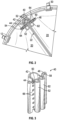
- the clamp members 104 and 106 can remain in the configuration illustrated in FIG. 5 , and the leaflet-engaging portions 114A and 120A can cooperate to clamp the leaflets 20 at a first location, and the leaflet-engaging portions 114B and 120B can clamp the leaflets at a second location adjacent the first location.
- the leaflets 20 can articulate about axes adjacent the leaflet-engaging portions 114B and 120B, and offset radially inwardly from the frame 12.
- clamping the leaflets at multiple locations can increase the overall clamping force of the clamp 100 against the leaflets.
- the leaflet-engaging portions 114A and 120A can also provide elastic strain-recovery shape-maintenance functionality, which is described in greater detail in U.S. Application No. 15/978,459, filed on May 14, 2018 , which is incorporated herein by reference.
- the tab portions of the leaflets can be folded around or beside the clamping members of the commissure clamp to stabilize the commissure and prevent rotation of the leaflets during valve operation.
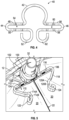
- FIG. 13 illustrates an embodiment in which a reinforcing member configured as a fabric strip 248 is wrapped around the clamping member 208 and forms a loop 250.
- the fabric strip 248 can extend from the loop 250, and can be positioned on or around the radially inward-facing surface of the leaflet tab 242.
- the leaflet tab 242 can be folded on itself to form a cuff 252 having a first layer 260 and a second layer 262. More particularly, the cuff 252 can be folded about a fold line extending into the plane of the page in FIG.
- the commissure clamp 300 When the commissure clamp 300 is disposed on the actuator component 328, the loops 320 and 326 can be received in the groove 334.
- the portions 312 and 314 of the first collar portion 304 can be received in the grooves 338, and the portions 316 and 318 of the collar portion 306 can be received in the grooves 340.
- the grooves on both sides of the actuator component 328 help align the commissure clamp at its proper location on the actuator component during assembly, assist in retaining the commissure clamp in place on the actuator component, and minimize the extent that portions of the clamp extend from the actuator component in a radial direction so as to further minimize the crimped profile of the prosthetic valve.
- the clamping members 308 and 310 can be movable between an open position and a closed position in order to position the commissure clamp around the actuator component 228 and clamp leaflets against the actuator component, similar to the embodiments described above.
- FIG. 24B illustrates a top plan view of the commissure assembly 442.
- the leaflet tab and/or tabs 444 of the leaflet 438 can be wrapped or folded around the axial member 408 such that there are three layers 458A, 458B, and 458C ( FIG. 24C ).
- the tab 450 of the leaflet 440 can be wrapped or can extend around the axial member 410.
- upper tabs of the leaflets can be folded downwardly at a location radially outward of the members 408 and 410.
- a stitch protector member 456 can be disposed around the axial member 408 between the axial member and the layers of the leaflet tab 444.
- the inner perimeter of the collar portion 502 can comprise a first inwardly-extending projection or protrusion 512 and a second inwardly-extending projection or protrusion 514 on the opposite side of the collar from the first projection and oriented generally toward the first projection.
- the collar portion 502 of the commissure attachment element 500 can be configured for attachment to a post or actuator component 516 of a mechanically-expandable prosthetic heart valve adapted to receive the collar portion.
- the actuator component 516 can comprise a notch, slot, or recess 518 shaped to correspond to the projection 512 and a notch, slot, or recess 520 shaped to correspond to the projection 514.
- the projections 512 and 514 can be configured to contact the radially inward surfaces of the recesses 518 and 520, such as during diastole. During diastole, the leaflets of the commissure can tend to pull the commissure support element radially inwardly in the direction of arrow 521. Thus, the projections 512 and 514 can contact the walls of the recesses 518 and 520 of the actuator component to brace the support element and prevent significant motion of the support element. This interaction can also relieve a substantial proportion of the stress or force applied to the rear (e.g., radially outward) member 522 of the collar portion 502, allowing the rear member 522 to be made thinner. This, in turn, can decrease the crimped diameter or profile of the prosthetic heart valve. The side portions of the collar member from which the projections extend can also be thicker to accommodate the forces.
- first and second members 506 and 508 are coupled together at their inflow ends by the cross member 510.
- the cross member 510 can be omitted, as in the embodiment of FIG. 27 .
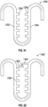
- FIG. 28 illustrates another configuration of the commissure support element 500 in which the first and second members 506 and 508 and/or the cross member 510 include a plurality of openings 524 (e.g., at the inflow and outflow ends of the members 506 and 508).
- Suture(s) can be inserted or threaded through the openings to attach the commissure support element to an actuator component, and/or to attach leaflets to the commissure support element.
- sutures can be threaded or looped between the upper openings 524 such that the sutures extend above the leaflet tabs to retain the leaflets in position, and/or to draw the upper portions of the members 506 and 508 toward one another to apply pressure to the leaflet tabs.
- sutures can be inserted through the openings 528 to attach the commissure support member and/or the commissure to an actuator component.
- the first and second members of FIG. 28 can comprise openings arranged in columns similar to FIG. 29 .
- the curved members 602 and 608 can lengthen the first and second members 606 and 610. This, in turn, can lengthen the leaflet-receiving window 612.
- the longer leaflet-receiving window can reduce stress on the leaflets and the corresponding risk of tearing during valve operation.
- FIG. 31 illustrates a side elevation view of a commissure 614 including leaflets 616 received in the commissure support element 600. The actuator component and frame of the prosthetic valve are omitted for clarity.
- the longer leaflet-receiving window 612 ( FIG. 30 ) can allow the window to accommodate leaflet tabs 618 which include additional tabs 620 disposed along the outflow edge 622 of the leaflets 616.
- the additional leaflet tabs 620, and/or lengthened leaflet tabs 618, together with the longer leaflet-receiving window 612, can result in a more even stress distribution along the leaflet tabs at the location(s) of attachment to the commissure support element. Including the additional leaflet tabs 620 can also result in the development of maximum stresses within the bodies of the leaflets, rather than at the outflow edges, reducing the risk of tearing.
- the curved members 602 and 608 may also be positioned closer together.
- the collar portion 602 can be configured similarly to the collar portion 404 of FIG. 20A , and the curved members can extend from the location of attachment of the members 408 and 410.
- Such a configuration can be configured to lock or snap into place on the actuator component, as described above.
- Curved members such as the members 602 and 608 can be incorporated into any of the commissure support element embodiments described herein.
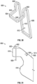
- FIGS. 32 and 33 illustrate another embodiment of a commissure support element 700 configured as a unitary wire-form body 702 including a coupling portion 704 ( FIG. 33 ) and a leaflet-receiving window 706 ( FIG. 32 ) defined by axially-extending first and second members 708 and 710.
- the coupling portion 704 can comprise a pair of coupling members 712 and 714.
- the coupling member 712 can be coupled to the first axial member 708 by a curved portion or member 716
- the coupling member 714 can be coupled to the second axial member 710 by a curved portion or member 718.
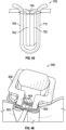
- the commissure support element 700 can be received by or coupled to a post or actuator component 722 of a mechanically-expandable prosthetic heart valve, which can be configured similarly to any of the actuator components described herein.
- the actuator component 722 can comprise a pair of tubular openings or channels 724 and 726 configured to receive the coupling members 712 and 714, respectively.
- the channels 724 and 726 can be located on the sides of the actuator component at the outflow end portion 728 of the actuator component, although the channels may be located anywhere around the perimeter of the actuator component and at any location along its length.
- the commissure support element 700 can be configured such that when coupled to the actuator component 722, the curved members 716 and 718 extend above (e.g., in the outflow direction) an upper surface 730 of the actuator component, although the support element may also be disposed elsewhere along the length of the actuator component between the inflow and outflow end portions of the actuator component.
- FIGS. 35 and 36 illustrate the steps of coupling the commissure support member 700 to the actuator component 722, according to one embodiment.
- the coupling member 712 ( FIG. 33 ) can be inserted into the corresponding channel 724 with the commissure support element rotated such that the coupling member 714 is disposed radially inwardly of the actuator component 722.
- the coupling member 712 may be inserted into the actuator component first. With the coupling member 712 at least partially advanced into the channel 724, the commissure support element can be rotated about the coupling member 712 to align the coupling member 714 with the channel 726.
- the commissure support element can then be advanced in the direction of the inflow end of the prosthetic valve such that the coupling members 712 and 714 are inserted into the corresponding channels 724 and 726 by a specified distance.
- inserting the coupling members into the actuator component one at a time can simplify the assembly process, although the coupling members may also be advanced into the openings at the same time.
- first and second axial members 708 and 710 can be angled toward each other such that the leaflet-receiving window 706 is V-shaped.
- first and second axial members 708 and 710 can overlap at any location along their lengths (e.g., to form an "X" or cross).
- the first and second axial members 708 and 710 can be pulled apart or opened in order to receive the leaflets of a commissure, and can return to the overlapped configuration to press the leaflets together.
- the commissure support elements described herein can be coupled to the actuator components such that the first and second axial members extend from the coupling portion upwardly in the direction of the inflow end of the prosthetic valve.
- FIG. 38 illustrates another embodiment of the commissure support element 700 configured for attachment to an actuator element with the member 720 located at the outflow end of the element
- FIG. 39 shows the element 700 coupled to a modified embodiment of the actuator component 722.
- the channels 724 and 726 can be located between the inflow end 736 and the outflow end 728 of the actuator component, such as offset from the outflow surface 730 in a direction toward the hinge pin member 738, or located between the pin member 738 and the surface 730.
- the curved members 716 and 718 can curve upwardly such that the first and second axial members 708 and 710 extend in the direction of the outflow end of the prosthetic valve.
- the angle of the first and second members 708 and 710 relative to the actuator component 722 can be varied.
- the first and second members 708 and 710 can be parallel, or substantially parallel, to the longitudinal axis of the actuator component 722.
- the first and second members 708 and 710 can be flexible, and can be angled away from the actuator component 722 and radially inwardly toward the central axis of the prosthetic valve ( FIG. 1 ).
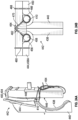
- the angle of the axial members can change during valve operation, for example by flexing about the curved members 716 and 718. This can allow a more even stress distribution along the attachment between the leaflets 746 and the commissure support element 700 during valve operation, and particularly during diastole, as indicated schematically in FIGS. 40 and 41 .
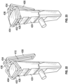
- FIG. 42 illustrates another embodiment in which a commissure member or plate 740 is coupled to the actuator component 722.
- the commissure plate 740 can comprise a portion or flange 742 comprising a plurality of openings 744.
- the commissure plate 740 can comprise a similarly configured flange on both sides of the actuator element, or on only one side.
- the commissure plate 740 can be sutured to the actuator component 722 by sutures extending through the openings 744.
- the commissure plate 740 can include the channels 724 and 726 for receiving the coupling members of the commissure support element.
- the commissure plate 740 can be integrally formed with the commissure support element 700, or with the actuator component 722. The leaflets of the commissure can also be sutured to the commissure plate 740 through the openings 744.
- FIG. 45 illustrates a commissure support element 700 comprising suture 748 wrapped around the outflow ends of the first and second axial members 708, 710 above the leaflets 750 to press the members against the leaflets 750.
- FIG. 47 illustrates another configuration of the commissure support element comprising notches 752 in the axial members 708 and 710 to retain the sutures 748.
- FIG. 46 illustrates a commissure support element 800 configured similarly to the support element 400 comprising sutures 802 wrapped around members 804 and 806 coupling the collar portion 808 to the axial members.
- FIG. 48 illustrates another embodiment of a commissure support element 900 configured similarly to the support element 700, wherein the first and second axial members 902 and 904 comprise opposing protrusions 906 and 908 that can contact each other to limit the degree to which the axial members may deflect toward one another (e.g., when suture is tied around them as in FIG. 45 ).
- FIG. 49 illustrates another embodiment of a commissure support member 1000 configured similarly to the support element 700, and in which the first and second axial members 1002, 1004 comprise complementary clasp members 1006 and 1008.
- the clasp members 1006 and 1008 can prevent the axial members 1002 and 1004 from moving apart.
- the length of the clasp members 1006 and 1008 can determine the spacing of the axial members 1002 and 1004, and the pressure applied to leaflets received between them.
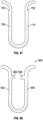
- FIG. 50A illustrates another embodiment of a commissure support element 1100 configured similarly to the support element 700, wherein the first and second axial members 1102 and 1104 comprise flexible tab portions 1106 and 1108 extending along at least a portion of the length of the axial members, and extending inwardly toward each other across the leaflet-receiving window 1110.
- the tab portions 1106 and 1108 can comprise a flexible material, and can be sized such that when leaflets are inserted between the axial members, the tab portions rotate or flex radially inwardly (or radially outwardly) to resiliently engage the leaflets.
- 50B is a schematic cross-sectional view of the first and second axial members 1102 and 1104 showing the flexible tab portions 1106 and 1108 in their neutral, undeflected position, and in their rotated or deflected position 1106' and 1108'.
- the flexible tab portions 1106 and 1108 can rotate about their central axes.
- the flexible tab portions 1106 and 1108 can be integrally formed with the first and second axial members 1102 and 1104, or separately formed and attached to the axial members, depending upon the particular characteristics desired.
- FIG. 52 illustrates an embodiment of a commissure support element 1300 comprising clasp elements 1302 and 1304 similar to the clasps 1006 and 1008 of FIG. 49 in combination with projections 1306 similar to the projections 1206 of FIG. 51 .
- FIG. 53 illustrates another embodiment in which the commissure support element 1400 comprises suture retaining notches 1402 for retaining sutures and protrusions 1404 configured to maintain a minimum spacing between the axial members 1406 and 1408. Any combination of any number of the features described herein is contemplated by this disclosure.
- any of the commissure support elements disclosed herein can be formed by bending a piece of wire (e.g., a straight piece of wire) into the specified shape and securing the free ends of the wire together, such as by welding.
- the commissure support elements can also be formed using other techniques including, for example, molding (e.g., injection molding), machining (e.g., laser cutting), and/or 3D printing, and bending or folding the elements into the specified shape as needed.
- a frame of a prosthetic valve can have axially extending posts that are separate from the actuator components for mounting the commissure support elements.
- a frame can have a plurality of posts corresponding to the number of commissures (e.g., three posts for three commissures), with each post being mounted to the inner surface of the frame (e.g., to selected struts 26 of the frame) between two adjacent actuator components 32.
- commissure support elements described herein may also be used with prosthetic heart valves that do not have actuators, such as self-expandable prosthetic heart valves or plastically-expandable prosthetic heart valves (e.g., such as those that are expanded to their functional size by inflating a balloon).
- actuators such as self-expandable prosthetic heart valves or plastically-expandable prosthetic heart valves (e.g., such as those that are expanded to their functional size by inflating a balloon).
- self-expandable prosthetic heart valves can be found in U.S. Patent No. 8,652,202 , U.S. Patent No. 9,155,619 , and U.S. Publication No. 2014/0343670 , which are incorporated herein by reference.
- plastically-expandable prosthetic heart valves can be found in U.S. Patent No. 9,393,110 , and U.S. Publication No. 2018/0028310 , which are incorporated herein by reference.
- integrally formed and unitary construction refer to a construction that does not include any welds, fasteners, or other means for securing separately formed pieces of material to each other.
Landscapes
- Health & Medical Sciences (AREA)
- Cardiology (AREA)
- Engineering & Computer Science (AREA)
- Biomedical Technology (AREA)
- Heart & Thoracic Surgery (AREA)
- Transplantation (AREA)
- Oral & Maxillofacial Surgery (AREA)
- Vascular Medicine (AREA)
- Life Sciences & Earth Sciences (AREA)
- Animal Behavior & Ethology (AREA)
- General Health & Medical Sciences (AREA)
- Public Health (AREA)
- Veterinary Medicine (AREA)
- Prostheses (AREA)
Applications Claiming Priority (3)
| Application Number | Priority Date | Filing Date | Title |
|---|---|---|---|
| US201862767412P | 2018-11-14 | 2018-11-14 | |
| PCT/US2019/061392 WO2020102487A1 (en) | 2018-11-14 | 2019-11-14 | Prosthetic heart valve having commissure support element |
| EP19817061.5A EP3880127B1 (de) | 2018-11-14 | 2019-11-14 | Herzklappenprothese mit kommissurstützelement |
Related Parent Applications (1)
| Application Number | Title | Priority Date | Filing Date |
|---|---|---|---|
| EP19817061.5A Division EP3880127B1 (de) | 2018-11-14 | 2019-11-14 | Herzklappenprothese mit kommissurstützelement |
Publications (2)
| Publication Number | Publication Date |
|---|---|
| EP4397278A2 true EP4397278A2 (de) | 2024-07-10 |
| EP4397278A3 EP4397278A3 (de) | 2024-09-11 |
Family
ID=68808596
Family Applications (2)
| Application Number | Title | Priority Date | Filing Date |
|---|---|---|---|
| EP19817061.5A Active EP3880127B1 (de) | 2018-11-14 | 2019-11-14 | Herzklappenprothese mit kommissurstützelement |
| EP24158262.6A Pending EP4397278A3 (de) | 2018-11-14 | 2019-11-14 | Herzklappenprothese mit kommissurenunterstützungselement |
Family Applications Before (1)
| Application Number | Title | Priority Date | Filing Date |
|---|---|---|---|
| EP19817061.5A Active EP3880127B1 (de) | 2018-11-14 | 2019-11-14 | Herzklappenprothese mit kommissurstützelement |
Country Status (11)
| Country | Link |
|---|---|
| US (1) | US20210259833A1 (de) |
| EP (2) | EP3880127B1 (de) |
| JP (2) | JP7577059B2 (de) |
| KR (1) | KR20210091756A (de) |
| CN (2) | CN215425315U (de) |
| AU (1) | AU2019381720A1 (de) |
| CA (1) | CA3118699A1 (de) |
| CR (1) | CR20210227A (de) |
| SG (1) | SG11202104805TA (de) |
| WO (1) | WO2020102487A1 (de) |
| ZA (1) | ZA202102972B (de) |
Families Citing this family (13)
| Publication number | Priority date | Publication date | Assignee | Title |
|---|---|---|---|---|
| EP3880127B1 (de) * | 2018-11-14 | 2024-02-21 | Edwards Lifesciences Corporation | Herzklappenprothese mit kommissurstützelement |
| EP3934582A1 (de) * | 2019-03-04 | 2022-01-12 | Edwards Lifesciences Corporation | Nahtbefestigungsfunktion für eine herzklappenprothese |
| EP4003230B1 (de) * | 2019-07-31 | 2024-12-04 | St. Jude Medical, Cardiology Division, Inc. | Wechselstent-caf-design für tavr |
| EP4069144A1 (de) * | 2019-12-06 | 2022-10-12 | Edwards Lifesciences Corporation | Herzklappenprothesen mit kommissurenständerprotrusionen zur arretierung der kommissurenanordnungsposition |
| WO2021141878A1 (en) | 2020-01-10 | 2021-07-15 | Edwards Lifesciences Corporation | Assembly methods for a prosthetic heart valve leaflet |
| CN216962745U (zh) * | 2020-07-13 | 2022-07-15 | 爱德华兹生命科学公司 | 一种假体瓣膜 |
| WO2022020229A1 (en) | 2020-07-21 | 2022-01-27 | Edwards Lifesciences Corporation | Prosthetic heart valves with h-shaped commissure windows and methods for assembly thereof |
| EP4178490B1 (de) | 2020-08-12 | 2025-10-15 | Edwards Lifesciences Corporation | Herzklappenprothese |
| EP4609836A3 (de) | 2020-09-09 | 2025-11-19 | Edwards Lifesciences Corporation | Konische herzklappenprothesen mit klappenstrukturen zur formung konischer strömungskanäle |
| EP4225212A1 (de) * | 2020-10-06 | 2023-08-16 | Edwards Lifesciences Corporation | Kommissurverriegelungselement |
| WO2022103845A1 (en) | 2020-11-11 | 2022-05-19 | Edwards Lifesciences Corporation | Prosthetic heart valves with sealing frames to reduce paravalvular leakage |
| CN217793469U (zh) | 2021-04-22 | 2022-11-15 | 爱德华兹生命科学公司 | 具有齿合锁定机构的假体心脏瓣膜及其组件 |
| WO2024158597A2 (en) * | 2023-01-25 | 2024-08-02 | Medtronic, Inc. | Prosthetic heart valve |
Citations (8)
| Publication number | Priority date | Publication date | Assignee | Title |
|---|---|---|---|---|
| US5411522A (en) | 1993-08-25 | 1995-05-02 | Linvatec Corporation | Unitary anchor for soft tissue fixation |
| US6730118B2 (en) | 2001-10-11 | 2004-05-04 | Percutaneous Valve Technologies, Inc. | Implantable prosthetic valve |
| US8652202B2 (en) | 2008-08-22 | 2014-02-18 | Edwards Lifesciences Corporation | Prosthetic heart valve and delivery apparatus |
| US20140343670A1 (en) | 2013-05-20 | 2014-11-20 | Edwards Lifesciences Corporation | Prosthetic heart valve delivery apparatus |
| US9155619B2 (en) | 2011-02-25 | 2015-10-13 | Edwards Lifesciences Corporation | Prosthetic heart valve delivery apparatus |
| US9393110B2 (en) | 2010-10-05 | 2016-07-19 | Edwards Lifesciences Corporation | Prosthetic heart valve |
| US20180028310A1 (en) | 2016-08-01 | 2018-02-01 | Edwards Lifesciences Corporation | Prosthetic heart valve |
| US20180153689A1 (en) | 2016-12-06 | 2018-06-07 | Edwards Lifesciences Corporation | Mechanically expanding heart valve and delivery apparatus therefor |
Family Cites Families (12)
| Publication number | Priority date | Publication date | Assignee | Title |
|---|---|---|---|---|
| CN101415379B (zh) * | 2006-02-14 | 2012-06-20 | 萨德拉医学公司 | 用于输送医疗植入物的系统 |
| US8845720B2 (en) * | 2010-09-27 | 2014-09-30 | Edwards Lifesciences Corporation | Prosthetic heart valve frame with flexible commissures |
| US8795357B2 (en) * | 2011-07-15 | 2014-08-05 | Edwards Lifesciences Corporation | Perivalvular sealing for transcatheter heart valve |
| US20130023984A1 (en) * | 2011-07-20 | 2013-01-24 | Edwards Lifesciences Corporation | Commissure modification of prosthetic heart valve frame for improved leaflet attachment |
| US9827093B2 (en) * | 2011-10-21 | 2017-11-28 | Edwards Lifesciences Cardiaq Llc | Actively controllable stent, stent graft, heart valve and method of controlling same |
| EP4049625B1 (de) * | 2011-12-09 | 2025-01-08 | Edwards Lifesciences Corporation | Herzklappenprothese mit verbesserten kommissurstützen |
| EP3068346B1 (de) * | 2013-11-11 | 2021-03-03 | Edwards Lifesciences CardiAQ LLC | Verfahren zur herstellung eines stentrahmens für eine klappenprothese |
| US9855141B2 (en) * | 2014-12-18 | 2018-01-02 | W. L. Gore & Associates, Inc. | Prosthetic valves with mechanically coupled leaflets |
| CN109758266B (zh) * | 2014-12-18 | 2021-01-01 | W.L.戈尔及同仁股份有限公司 | 带有机械联接的瓣叶的假体瓣膜 |
| US10426617B2 (en) | 2015-03-06 | 2019-10-01 | Boston Scientific Scimed, Inc. | Low profile valve locking mechanism and commissure assembly |
| US10080653B2 (en) * | 2015-09-10 | 2018-09-25 | Edwards Lifesciences Corporation | Limited expansion heart valve |
| EP3880127B1 (de) * | 2018-11-14 | 2024-02-21 | Edwards Lifesciences Corporation | Herzklappenprothese mit kommissurstützelement |
-
2019
- 2019-11-14 EP EP19817061.5A patent/EP3880127B1/de active Active
- 2019-11-14 WO PCT/US2019/061392 patent/WO2020102487A1/en not_active Ceased
- 2019-11-14 AU AU2019381720A patent/AU2019381720A1/en not_active Abandoned
- 2019-11-14 CA CA3118699A patent/CA3118699A1/en active Pending
- 2019-11-14 KR KR1020217017670A patent/KR20210091756A/ko active Pending
- 2019-11-14 CN CN201921973532.8U patent/CN215425315U/zh active Active
- 2019-11-14 EP EP24158262.6A patent/EP4397278A3/de active Pending
- 2019-11-14 JP JP2021526337A patent/JP7577059B2/ja active Active
- 2019-11-14 CN CN201980074770.1A patent/CN112996461B/zh active Active
- 2019-11-14 CR CR20210227A patent/CR20210227A/es unknown
- 2019-11-14 SG SG11202104805TA patent/SG11202104805TA/en unknown
-
2021
- 2021-05-03 ZA ZA2021/02972A patent/ZA202102972B/en unknown
- 2021-05-13 US US17/320,004 patent/US20210259833A1/en active Pending
-
2024
- 2024-06-06 JP JP2024092332A patent/JP2024124411A/ja active Pending
Patent Citations (8)
| Publication number | Priority date | Publication date | Assignee | Title |
|---|---|---|---|---|
| US5411522A (en) | 1993-08-25 | 1995-05-02 | Linvatec Corporation | Unitary anchor for soft tissue fixation |
| US6730118B2 (en) | 2001-10-11 | 2004-05-04 | Percutaneous Valve Technologies, Inc. | Implantable prosthetic valve |
| US8652202B2 (en) | 2008-08-22 | 2014-02-18 | Edwards Lifesciences Corporation | Prosthetic heart valve and delivery apparatus |
| US9393110B2 (en) | 2010-10-05 | 2016-07-19 | Edwards Lifesciences Corporation | Prosthetic heart valve |
| US9155619B2 (en) | 2011-02-25 | 2015-10-13 | Edwards Lifesciences Corporation | Prosthetic heart valve delivery apparatus |
| US20140343670A1 (en) | 2013-05-20 | 2014-11-20 | Edwards Lifesciences Corporation | Prosthetic heart valve delivery apparatus |
| US20180028310A1 (en) | 2016-08-01 | 2018-02-01 | Edwards Lifesciences Corporation | Prosthetic heart valve |
| US20180153689A1 (en) | 2016-12-06 | 2018-06-07 | Edwards Lifesciences Corporation | Mechanically expanding heart valve and delivery apparatus therefor |
Also Published As
| Publication number | Publication date |
|---|---|
| CR20210227A (es) | 2021-08-18 |
| JP7577059B2 (ja) | 2024-11-01 |
| WO2020102487A1 (en) | 2020-05-22 |
| CN215425315U (zh) | 2022-01-07 |
| JP2024124411A (ja) | 2024-09-12 |
| CA3118699A1 (en) | 2020-05-22 |
| JP2022507421A (ja) | 2022-01-18 |
| CN112996461B (zh) | 2024-02-27 |
| EP3880127A1 (de) | 2021-09-22 |
| ZA202102972B (en) | 2022-08-31 |
| AU2019381720A1 (en) | 2021-05-27 |
| SG11202104805TA (en) | 2021-06-29 |
| US20210259833A1 (en) | 2021-08-26 |
| EP3880127B1 (de) | 2024-02-21 |
| CN112996461A (zh) | 2021-06-18 |
| EP4397278A3 (de) | 2024-09-11 |
| KR20210091756A (ko) | 2021-07-22 |
Similar Documents
| Publication | Publication Date | Title |
|---|---|---|
| EP3880127B1 (de) | Herzklappenprothese mit kommissurstützelement | |
| US12318285B2 (en) | Mechanically expandable heart valve | |
| US12201522B2 (en) | Mechanically expandable heart valve | |
| US12433747B2 (en) | Commissure attachment for prosthetic heart valve | |
| EP3784172B1 (de) | Mechanisch expandierbare herzklappe mit segelklemmen | |
| WO2021158722A1 (en) | Prosthetic heart valve leaflet commissure assemblies and methods | |
| WO2025221856A1 (en) | Prosthetic valves and unitary valvular structures thereof | |
| US12611301B2 (en) | Commissure locking member | |
| HK40026597A (en) | Mechanically expandable heart valve |
Legal Events
| Date | Code | Title | Description |
|---|---|---|---|
| PUAI | Public reference made under article 153(3) epc to a published international application that has entered the european phase |
Free format text: ORIGINAL CODE: 0009012 |
|
| STAA | Information on the status of an ep patent application or granted ep patent |
Free format text: STATUS: THE APPLICATION HAS BEEN PUBLISHED |
|
| AC | Divisional application: reference to earlier application |
Ref document number: 3880127 Country of ref document: EP Kind code of ref document: P |
|
| AK | Designated contracting states |
Kind code of ref document: A2 Designated state(s): AL AT BE BG CH CY CZ DE DK EE ES FI FR GB GR HR HU IE IS IT LI LT LU LV MC MK MT NL NO PL PT RO RS SE SI SK SM TR |
|
| PUAL | Search report despatched |
Free format text: ORIGINAL CODE: 0009013 |
|
| AK | Designated contracting states |
Kind code of ref document: A3 Designated state(s): AL AT BE BG CH CY CZ DE DK EE ES FI FR GB GR HR HU IE IS IT LI LT LU LV MC MK MT NL NO PL PT RO RS SE SI SK SM TR |
|
| RIC1 | Information provided on ipc code assigned before grant |
Ipc: A61F 2/24 20060101AFI20240805BHEP |
|
| P01 | Opt-out of the competence of the unified patent court (upc) registered |
Free format text: CASE NUMBER: APP_53359/2024 Effective date: 20240925 |
|
| STAA | Information on the status of an ep patent application or granted ep patent |
Free format text: STATUS: REQUEST FOR EXAMINATION WAS MADE |
|
| 17P | Request for examination filed |
Effective date: 20250311 |