CN114449980A - Prosthetic heart valve with commissure post protrusions for commissure assembly position locking - Google Patents
Prosthetic heart valve with commissure post protrusions for commissure assembly position locking Download PDFInfo
- Publication number
- CN114449980A CN114449980A CN202080067964.1A CN202080067964A CN114449980A CN 114449980 A CN114449980 A CN 114449980A CN 202080067964 A CN202080067964 A CN 202080067964A CN 114449980 A CN114449980 A CN 114449980A
- Authority
- CN
- China
- Prior art keywords
- commissure
- support post
- tab
- commissure support
- assembly
- Prior art date
- Legal status (The legal status is an assumption and is not a legal conclusion. Google has not performed a legal analysis and makes no representation as to the accuracy of the status listed.)
- Pending
Links
Images


Classifications
-
- A—HUMAN NECESSITIES
- A61—MEDICAL OR VETERINARY SCIENCE; HYGIENE
- A61F—FILTERS IMPLANTABLE INTO BLOOD VESSELS; PROSTHESES; DEVICES PROVIDING PATENCY TO, OR PREVENTING COLLAPSING OF, TUBULAR STRUCTURES OF THE BODY, e.g. STENTS; ORTHOPAEDIC, NURSING OR CONTRACEPTIVE DEVICES; FOMENTATION; TREATMENT OR PROTECTION OF EYES OR EARS; BANDAGES, DRESSINGS OR ABSORBENT PADS; FIRST-AID KITS
- A61F2/00—Filters implantable into blood vessels; Prostheses, i.e. artificial substitutes or replacements for parts of the body; Appliances for connecting them with the body; Devices providing patency to, or preventing collapsing of, tubular structures of the body, e.g. stents
- A61F2/02—Prostheses implantable into the body
- A61F2/24—Heart valves ; Vascular valves, e.g. venous valves; Heart implants, e.g. passive devices for improving the function of the native valve or the heart muscle; Transmyocardial revascularisation [TMR] devices; Valves implantable in the body
- A61F2/2412—Heart valves ; Vascular valves, e.g. venous valves; Heart implants, e.g. passive devices for improving the function of the native valve or the heart muscle; Transmyocardial revascularisation [TMR] devices; Valves implantable in the body with soft flexible valve members, e.g. tissue valves shaped like natural valves
- A61F2/2418—Scaffolds therefor, e.g. support stents
-
- A—HUMAN NECESSITIES
- A61—MEDICAL OR VETERINARY SCIENCE; HYGIENE
- A61F—FILTERS IMPLANTABLE INTO BLOOD VESSELS; PROSTHESES; DEVICES PROVIDING PATENCY TO, OR PREVENTING COLLAPSING OF, TUBULAR STRUCTURES OF THE BODY, e.g. STENTS; ORTHOPAEDIC, NURSING OR CONTRACEPTIVE DEVICES; FOMENTATION; TREATMENT OR PROTECTION OF EYES OR EARS; BANDAGES, DRESSINGS OR ABSORBENT PADS; FIRST-AID KITS
- A61F2/00—Filters implantable into blood vessels; Prostheses, i.e. artificial substitutes or replacements for parts of the body; Appliances for connecting them with the body; Devices providing patency to, or preventing collapsing of, tubular structures of the body, e.g. stents
- A61F2/02—Prostheses implantable into the body
- A61F2/24—Heart valves ; Vascular valves, e.g. venous valves; Heart implants, e.g. passive devices for improving the function of the native valve or the heart muscle; Transmyocardial revascularisation [TMR] devices; Valves implantable in the body
- A61F2/2427—Devices for manipulating or deploying heart valves during implantation
- A61F2/2436—Deployment by retracting a sheath
-
- A—HUMAN NECESSITIES
- A61—MEDICAL OR VETERINARY SCIENCE; HYGIENE
- A61F—FILTERS IMPLANTABLE INTO BLOOD VESSELS; PROSTHESES; DEVICES PROVIDING PATENCY TO, OR PREVENTING COLLAPSING OF, TUBULAR STRUCTURES OF THE BODY, e.g. STENTS; ORTHOPAEDIC, NURSING OR CONTRACEPTIVE DEVICES; FOMENTATION; TREATMENT OR PROTECTION OF EYES OR EARS; BANDAGES, DRESSINGS OR ABSORBENT PADS; FIRST-AID KITS
- A61F2/00—Filters implantable into blood vessels; Prostheses, i.e. artificial substitutes or replacements for parts of the body; Appliances for connecting them with the body; Devices providing patency to, or preventing collapsing of, tubular structures of the body, e.g. stents
- A61F2/02—Prostheses implantable into the body
- A61F2/24—Heart valves ; Vascular valves, e.g. venous valves; Heart implants, e.g. passive devices for improving the function of the native valve or the heart muscle; Transmyocardial revascularisation [TMR] devices; Valves implantable in the body
- A61F2/2427—Devices for manipulating or deploying heart valves during implantation
- A61F2/2439—Expansion controlled by filaments
-
- A—HUMAN NECESSITIES
- A61—MEDICAL OR VETERINARY SCIENCE; HYGIENE
- A61F—FILTERS IMPLANTABLE INTO BLOOD VESSELS; PROSTHESES; DEVICES PROVIDING PATENCY TO, OR PREVENTING COLLAPSING OF, TUBULAR STRUCTURES OF THE BODY, e.g. STENTS; ORTHOPAEDIC, NURSING OR CONTRACEPTIVE DEVICES; FOMENTATION; TREATMENT OR PROTECTION OF EYES OR EARS; BANDAGES, DRESSINGS OR ABSORBENT PADS; FIRST-AID KITS
- A61F2/00—Filters implantable into blood vessels; Prostheses, i.e. artificial substitutes or replacements for parts of the body; Appliances for connecting them with the body; Devices providing patency to, or preventing collapsing of, tubular structures of the body, e.g. stents
- A61F2/02—Prostheses implantable into the body
- A61F2/24—Heart valves ; Vascular valves, e.g. venous valves; Heart implants, e.g. passive devices for improving the function of the native valve or the heart muscle; Transmyocardial revascularisation [TMR] devices; Valves implantable in the body
- A61F2/2442—Annuloplasty rings or inserts for correcting the valve shape; Implants for improving the function of a native heart valve
- A61F2/2463—Implants forming part of the valve leaflets
-
- A—HUMAN NECESSITIES
- A61—MEDICAL OR VETERINARY SCIENCE; HYGIENE
- A61F—FILTERS IMPLANTABLE INTO BLOOD VESSELS; PROSTHESES; DEVICES PROVIDING PATENCY TO, OR PREVENTING COLLAPSING OF, TUBULAR STRUCTURES OF THE BODY, e.g. STENTS; ORTHOPAEDIC, NURSING OR CONTRACEPTIVE DEVICES; FOMENTATION; TREATMENT OR PROTECTION OF EYES OR EARS; BANDAGES, DRESSINGS OR ABSORBENT PADS; FIRST-AID KITS
- A61F2250/00—Special features of prostheses classified in groups A61F2/00 - A61F2/26 or A61F2/82 or A61F9/00 or A61F11/00 or subgroups thereof
- A61F2250/0004—Special features of prostheses classified in groups A61F2/00 - A61F2/26 or A61F2/82 or A61F9/00 or A61F11/00 or subgroups thereof adjustable
- A61F2250/001—Special features of prostheses classified in groups A61F2/00 - A61F2/26 or A61F2/82 or A61F9/00 or A61F11/00 or subgroups thereof adjustable for adjusting a diameter
Abstract
A prosthetic heart valve includes an expandable annular frame and a valve structure. The annular frame has an inflow end and an outflow end spaced from the inflow end in an axial direction of the frame. The ring frame may also include a plurality of commissure support posts. The valve structure is supported within the annular frame and includes a plurality of valve leaflets. Each leaflet has a pair of tabs. The lugs of adjacent leaflets mate together to form a commissure lug assembly. Each commissure lug assembly is coupled to a respective one of the commissure support posts. Each commissure support post has a first portion with one or more protrusions disposed in an axial direction of the frame to limit axial movement of the respective commissure tab assembly.
Description
Cross Reference to Related Applications
This application claims the benefit of U.S. provisional application No. 62/945,029 entitled "Prosthetic Heart Valve Assemblies and Methods," filed on 6.12.2019, which is incorporated herein by reference in its entirety.
Technical Field
The present disclosure relates to prosthetic heart valves, and in particular, to attaching a commissure assembly of a valve structure of a prosthetic heart valve to a commissure post of a frame of the prosthetic heart valve.
Background
The human heart may suffer from various valvular diseases. These valve diseases can lead to significant cardiac dysfunction and ultimately require repair of the native valve or replacement of the native valve with a prosthetic valve. There are many known prosthetic devices (e.g., stents) and prosthetic valves, and many known methods of implanting these devices and valves in humans. Percutaneous minimally invasive surgical methods are used in a variety of procedures to deliver prosthetic medical devices to locations within the body that are not readily accessible by surgery or where access without surgery is desirable. In one particular example, a prosthetic heart valve can be mounted on a distal end of a delivery device in a crimped state and advanced through a patient's vasculature (e.g., through the femoral artery and aorta) until the prosthetic valve reaches an implantation site in the heart. The prosthetic valve is then expanded to its functional size, for example, by inflating a balloon on which the prosthetic valve is mounted, thereby actuating a mechanical actuator that applies an expansion force to the prosthetic valve, or by deploying the prosthetic valve from a sheath of a delivery device, such that the prosthetic valve is able to self-expand to its functional size.
Prosthetic valves that rely on mechanical actuators for expansion may be referred to as "mechanically expandable" prosthetic heart valves. The actuator typically takes the form of a cable, suture, wire, and/or shaft configured to transmit the expansion force from the handle of the delivery device to the prosthetic valve.
An expandable transcatheter heart valve may include a cylindrical metal frame or stent and prosthetic leaflets mounted within the frame. The leaflets can be attached to the commissure posts of the frame via the commissure tab assemblies. Each commissure tab assembly can be pre-assembled by attaching the tabs of adjacent leaflets to one another. The outermost portions of the commissure components can be wrapped around the commissure posts, and then the commissure components can be attached to the respective commissure posts of the frame with sutures.
This commissure mounting method can present manufacturing challenges because accurate positioning of the commissure components on the commissure posts can be difficult, and the location of the commissure components on the commissure posts can change during component handling, crimping, or valve expansion. Undesirable placement of the commissure components relative to the commissure posts can include rotation of the commissure components over the commissure posts such that the leaflet placement is no longer centered within the frame, sliding of the commissure components axially along the commissure posts such that a portion of the commissure components slide off the edges of the commissure posts (which can occur during valve crimping), and/or sliding of the commissure components axially along the commissure posts such that a portion of the commissure components are pressed against the frame commissures (which can also occur during valve crimping).
Accordingly, there is a need for improved prosthetic heart valves and methods for securing a leaflet assembly to a frame of a prosthetic heart valve.
Disclosure of Invention
Described herein are embodiments of prosthetic heart valves and methods for assembling prosthetic heart valves. In some embodiments, an expandable annular frame for a prosthetic heart valve may include a plurality of commissure support posts. Each commissure support post has projections that extend in a direction perpendicular to the longitudinal axis of the annular frame and limit movement of the commissure support posts of the commissure tab assembly along the leaflets of the valve structure. In some embodiments, the protrusion extends radially inward or in a circumferential direction of the annular frame. In some embodiments, sutures can be passed through one or more apertures of the projections, or through open slots formed by the projections, to further secure the commissure tab assemblies to the commissure support posts. In some embodiments, each commissure support post includes protrusions that limit movement of the commissure tab assemblies at opposite end portions of the commissure tab assemblies.
In one representative embodiment, a prosthetic heart valve can include an expandable annular frame and a valve structure. The annular frame can have a longitudinal axis and can include a plurality of commissure support posts. The valve structure can be supported by the frame and can include a plurality of leaflets. Each leaflet can have a pair of tabs. The lugs of adjacent leaflets can be mated together to form a commissure lug assembly. There can be one commissure post for each commissure tab assembly. Each commissure tab assembly is coupleable to a respective commissure support post, with one tab being at least partially wrapped around the commissure support post in a first direction and the other tab being at least partially wrapped around the commissure support post in a second direction. At least a first portion of each commissure support post may include at least one first projection extending in a direction perpendicular to the longitudinal axis and configured to limit axial movement of the respective commissure lug assembly in a downstream direction.
In another exemplary embodiment, a method of assembling a prosthetic heart valve can include positioning a commissure lug assembly on a respective commissure support post of an expandable annular frame having a longitudinal axis. Each commissural support post can have a first portion and a second portion. The first portion can be closer to an axial end of the annular frame than the second portion. The method can further include coupling each commissure lug assembly to a respective commissure support post. The arrangement can include wrapping one leaflet tab of the commissure tab assembly at least partially around the respective commissure support column in a first direction and wrapping the other leaflet tab of the commissure tab assembly at least partially around the respective commissure support column in a second direction. At least a first portion of each commissure support post may include at least one first projection extending in a direction perpendicular to the longitudinal axis and configured to limit movement of the respective commissure lug assembly toward the axial end portion of the ring frame.
In another representative embodiment, a prosthetic heart valve includes an annular frame and a valve structure. The annular frame is radially collapsible and expandable between a radially compressed configuration and a radially expanded configuration. The annular frame can have an inflow end and an outflow end separated from the inflow end in an axial direction of the frame. The ring frame may include a plurality of commissure support posts. The valve structure can be supported within the annular frame and can include a plurality of leaflets. Each leaflet can have a pair of tabs. The lugs of adjacent leaflets can be mated together to form a commissure lug assembly. There can be one commissure support post for each commissure lug assembly. Each commissure tab assembly can be coupled to a respective commissure support post, with one tab wrapping at least partially around the commissure support post in a first direction and the other tab wrapping at least partially around the commissure support post in a second direction. Each commissural support post can have a first portion with a pair of first projections projecting in opposite directions along a circumferential direction of the annular frame. For each commissure support post, a corresponding commissure lug assembly can be disposed in the axial direction between the first portion and the inflow end of the annular frame. For each commissure support post, the pair of first protrusions can be axially arranged so as to limit axial movement of the respective commissure lug assembly in the downstream direction.
In another representative embodiment, a prosthetic heart valve includes an annular frame and a valve structure. The annular frame is radially collapsible and expandable between a radially compressed configuration and a radially expanded configuration. The annular frame can have an inflow end and an outflow end separated from the inflow end in an axial direction of the frame. The ring frame may include a plurality of commissure support posts. The valve structure can be supported within the annular frame and can include a plurality of leaflets. Each leaflet can have a pair of tabs. The lugs of adjacent leaflets can be mated together to form a commissure lug assembly. There can be one commissure support post for each commissure lug assembly. Each commissure tab assembly can be coupled to a respective commissure support post, with one tab wrapping at least partially around the commissure support post in a first direction and the other tab wrapping at least partially around the commissure support post in a second direction. Each commissure support post can have a first portion with a first protrusion that protrudes in a radial direction of the annular frame towards an interior of the annular frame. For each commissure support post, a corresponding commissure lug assembly can be disposed in the axial direction between the first portion and the inflow end of the annular frame. For each commissure support post, the first projection can be axially arranged so as to limit axial movement of the respective commissure lug assembly in the downstream direction.
In another representative embodiment, a prosthetic heart valve includes an annular frame and a valve structure. The annular frame is radially collapsible and expandable between a radially compressed configuration and a radially expanded configuration. The annular frame can have an inflow end and an outflow end separated from the inflow end in an axial direction of the frame. The ring frame may include a plurality of commissure support posts. The valve structure can be supported within the annular frame and can include a plurality of leaflets. Each leaflet can have a pair of tabs. The lugs of adjacent leaflets can be mated together to form a commissure lug assembly. There is one commissure support post for each commissure lug assembly. Each commissure tab assembly can be coupled to a respective commissure support post, with one tab wrapping at least partially around the commissure support post in a first direction and the other tab wrapping at least partially around the commissure support post in a second direction. Each commissural support post can have a first portion with a pair of first projections projecting in opposite directions along a circumferential direction of the annular frame. Each first protrusion may have a neck portion with a first width and an end portion with a second width greater than the first width. The neck portion can be disposed in a circumferential direction between the end portion and a central portion of the first portion of the respective commissure support post such that at least one slot is formed between a surface of the central portion and a facing surface of the end portion. For each commissure support post, a corresponding commissure lug assembly can be disposed in the axial direction between the first portion and the inflow end of the annular frame. For each commissure support post, the pair of first protrusions can be axially arranged so as to limit axial movement of the respective commissure lug assembly in the downstream direction.
In another representative embodiment, a prosthetic heart valve includes an annular frame and a valve structure. The annular frame is radially collapsible and expandable between a radially compressed configuration and a radially expanded configuration. The annular frame can have an inflow end and an outflow end separated from the inflow end in an axial direction of the frame. The ring frame may include a plurality of commissure support posts. The valve structure can be supported within the annular frame and can include a plurality of leaflets. Each leaflet can have a pair of tabs. The lugs of adjacent leaflets can be mated together to form a commissure lug assembly. There can be one commissure support post for each commissure lug assembly. Each commissure tab assembly can be coupled to a respective commissure support post, with one tab wrapping at least partially around the commissure support post in a first direction and the other tab wrapping at least partially around the commissure support post in a second direction. Each commissure support post can have a first portion with a first protrusion that protrudes in a radial direction of the annular frame towards an interior of the annular frame. Each first protrusion may have a neck portion with a first width and an end portion with a second width greater than the first width. The neck portion can be disposed in a radial direction between the end portion and a central portion of the first portion of the respective commissure support post such that at least one slot is formed between a surface of the central portion and a facing surface of the end portion. For each commissure support post, a corresponding commissure lug assembly can be disposed in the axial direction between the first portion and the inflow end of the annular frame. For each commissure support post, the first projection can be axially arranged so as to limit axial movement of the respective commissure lug assembly in the downstream direction.
In another representative embodiment, a prosthetic heart valve includes an annular frame and a valve structure. The annular frame is radially collapsible and expandable between a radially compressed configuration and a radially expanded configuration. The annular frame can have an inflow end and an outflow end separated from the inflow end in an axial direction of the frame. The ring frame may include a plurality of commissure support posts. The valve structure can be supported within the annular frame and can include a plurality of leaflets. Each leaflet can have a pair of tabs. The lugs of adjacent leaflets can be mated together to form a commissure lug assembly. Each commissure lug assembly can be coupled to a respective commissure support post. The annular frame may include a member for limiting axial movement of the commissure lug assemblies.
In another representative embodiment, a method of assembling a prosthetic heart valve can include positioning commissure tab assemblies of leaflets of a valve structure on respective commissure support posts of an annular frame. The annular frame is radially collapsible and expandable between a radially compressed configuration and a radially expanded configuration. The annular frame can have an inflow end and an outflow end separated from the inflow end in an axial direction of the frame. The ring frame may include a plurality of commissure support posts. There can be one commissure support post for each commissure lug assembly. The valve structure may include a plurality of leaflets. Each leaflet can have a pair of tabs. Each commissure tab assembly can be formed from a pair of tabs of adjacent leaflets. The method can further include coupling each commissure lug assembly to its respective commissure support post. Each commissural support post can have a first portion with a pair of first projections projecting in opposite directions along a circumferential direction of the annular frame. For each commissure support post, a corresponding commissure lug assembly can be disposed in the axial direction between the first portion and the inflow end of the annular frame. For each commissure support post, the pair of first protrusions can be axially arranged so as to limit axial movement of the respective commissure lug assembly in the downstream direction.
In another representative embodiment, a method of assembling a prosthetic heart valve can include positioning commissure tab assemblies of leaflets of a valve structure on respective commissure support posts of an annular frame. The annular frame is radially collapsible and expandable between a radially compressed configuration and a radially expanded configuration. The annular frame can have an inflow end and an outflow end separated from the inflow end in an axial direction of the frame. The ring frame may include a plurality of commissure support posts. There can be one commissure support post for each commissure lug assembly. The valve structure may include a plurality of leaflets. Each leaflet can have a pair of tabs. Each commissure tab assembly can be formed from a pair of tabs of adjacent leaflets. The method can further include coupling each commissure lug assembly to its respective commissure support post. Each commissure support post can have a first portion with a first protrusion that protrudes in a radial direction of the annular frame towards an interior of the annular frame. For each commissure support post, a corresponding commissure lug assembly can be disposed in the axial direction between the first portion and the inflow end of the annular frame. For each commissure support post, a first projection can be disposed in the axial direction to limit axial movement of the respective commissure lug assembly in the downstream direction.
In another representative embodiment, a method of assembling a prosthetic heart valve can include positioning commissure tab assemblies of leaflets of a valve structure at respective commissure support posts of an annular frame. The annular frame is radially collapsible and expandable between a radially compressed configuration and a radially expanded configuration. The annular frame can have an inflow end and an outflow end separated from the inflow end in an axial direction of the frame. The ring frame may include a plurality of commissure support posts. There can be one commissure support post for each commissure lug assembly. The valve structure may include a plurality of leaflets. Each leaflet can have a pair of tabs. Each commissure tab assembly can be formed from a pair of tabs of adjacent leaflets. The method can further include coupling each commissure lug assembly to its respective commissure support post. Each commissural support post can have a first portion with a pair of first projections projecting in opposite directions along a circumferential direction of the annular frame. Each first protrusion may have a neck portion with a first width and an end portion with a second width greater than the first width. The neck portion can be disposed in a circumferential direction between the end portion and a central portion of the first portion of the respective commissure support post such that at least one slot is formed between a surface of the central portion and a facing surface of the end portion. For each commissure support post, a corresponding commissure lug assembly can be disposed in the axial direction between the first portion and the inflow end of the annular frame. For each commissure support post, the pair of first protrusions can be axially arranged so as to limit axial movement of the respective commissure lug assembly in the downstream direction.
In another representative embodiment, a method of assembling a prosthetic heart valve can include positioning commissure tab assemblies of leaflets of a valve structure on respective commissure support posts of an annular frame. The annular frame is radially collapsible and expandable between a radially compressed configuration and a radially expanded configuration. The annular frame can have an inflow end and an outflow end separated from the inflow end in an axial direction of the frame. The ring frame may include a plurality of commissure support posts. There can be one commissure support post for each commissure lug assembly. The valve structure may include a plurality of leaflets. Each leaflet can have a pair of tabs. Each commissure tab assembly can be formed from a pair of tabs of adjacent leaflets. The method can further include coupling each commissure lug assembly to its respective commissure support post. Each commissural support post can have a first portion with a pair of first protrusions that project toward the interior of the annular frame in the circumferential direction of the annular frame. Each first protrusion may have a neck portion with a first width and an end portion with a second width greater than the first width. The neck portion can be disposed in a radial direction between the end portion and a central portion of the first portion of the respective commissure support post such that at least one slot is formed between a surface of the central portion and a facing surface of the end portion. For each commissure support post, a corresponding commissure lug assembly can be disposed in the axial direction between the first portion and the inflow end of the annular frame. For each commissure support post, the first projection can be axially arranged so as to limit axial movement of the respective commissure lug assembly in the downstream direction.
In another representative embodiment, a method of assembling a prosthetic heart valve can include positioning commissure tab assemblies of leaflets of a valve structure on respective commissure support posts of an annular frame. The annular frame is radially collapsible and expandable between a radially compressed configuration and a radially expanded configuration. The annular frame can have an inflow end and an outflow end separated from the inflow end in an axial direction of the frame. The ring frame may include a plurality of commissure support posts. The valve structure may include a plurality of leaflets. Each leaflet can have a pair of tabs. Each commissure tab assembly can be formed from a pair of tabs of adjacent leaflets. The method can further include coupling each commissure lug assembly to its respective commissure support post. The annular frame may include a member for limiting axial movement of the commissure lug assemblies.
Any of the various innovations of the present disclosure can be used in combination or alone. This summary is provided to introduce a selection of concepts in a simplified form that are further described below in the detailed description. This summary is not intended to identify key features or essential features of the claimed subject matter, nor is it intended to be used to limit the scope of the claimed subject matter. The foregoing and other objects, features and advantages of the invention will become more apparent from the following detailed description of the preferred embodiments with reference to the accompanying drawings.
Drawings
Fig. 1 is a perspective view of an exemplary embodiment of a prosthetic heart valve.
Fig. 2 is a plan view of a single leaflet used to form a leaflet assembly of a prosthetic heart valve.
Figures 3A-3B are schematic views of various stages of assembly of the commissure lug assemblies to the commissure support posts, as viewed along a representative solid longitudinal axis of the prosthetic heart valve.
Figure 3C is a schematic view of the commissure tab assemblies secured to the commissure support posts as viewed in a radial direction from the exterior of the prosthetic heart valve.
Figures 4A-4B illustrate perspective views of a first example of a commissural support post without an installed and installed commissural lug assembly, respectively.
Figures 5A-5B illustrate perspective views of a second example of an articulating support post without an articulating lug assembly installed and installed, respectively.
Figures 6A-6B illustrate perspective views of a third example of an articulating support post without an articulating lug assembly installed and installed, respectively.
Figures 7A-7B illustrate perspective views of a fourth example of a commissural support post without an commissural tab assembly installed and installed, respectively.
Figures 8A-8B illustrate perspective views of a fifth example of a commissural support post without an installed and installed commissural lug assembly, respectively.
Figures 9A-9B illustrate perspective views of a sixth example of an articulating support post without an articulating lug assembly installed and installed, respectively.
Figures 10A-10B show perspective views of a seventh example of an articulating support post without an articulating lug assembly installed and installed, respectively.
11A-11B illustrate perspective views of an eighth example of an articulating support post without an articulating lug assembly mounted and installed, respectively.
Fig. 12A illustrates an exemplary prosthetic valve delivery device that can be used to implant the prosthetic heart valve of fig. 1.
Fig. 12B illustrates a perspective view of the distal portions of the delivery device and prosthetic valve shown in fig. 1 to illustrate the prosthetic valve in a radially expanded state.
Detailed Description
Examples of prosthetic heart valves, annular frames with commissure support posts, and leaflet assemblies for prosthetic heart valves, and methods for assembling the leaflet assemblies such that the commissure support posts of the annular frame form the prosthetic heart valve, are described herein. A prosthetic heart valve can include an annular frame with commissure support posts and a valve structure formed of leaflet assemblies supported by the frame. The leaflet assembly may include a plurality of leaflets, each leaflet having a pair of tabs. The lugs of adjacent leaflets can be coupled together to form a commissure lug assembly, and the leaflet assemblies can be supported by the frame via commissure lug assemblies that are respectively coupled to the commissure support posts. The commissure support posts can have one or more protrusions that extend radially inward or circumferentially. These protrusions can limit the movement of the respective commissure tab assemblies along their commissure support posts. In some embodiments, the commissure tab assemblies may be further coupled to the commissure support posts via one or more sutures extending through apertures in or slots formed by the protrusions. As a result, the position of the leaflet assembly for the prosthetic heart valve can be effectively locked in place during assembly and use of the prosthetic heart valve, and time and effort for securing the leaflet assembly to the frame of the prosthetic heart valve may be reduced.
Fig. 1 illustrates an exemplary prosthetic heart valve 10 according to one or more embodiments of the disclosed subject matter. The prosthetic heart valve 10 is radially compressible and expandable between a radially compressed configuration for delivery into a patient and a radially expanded configuration (shown in fig. 1). In certain embodiments, the prosthetic heart valve 10 can be implanted within the native aortic annulus, although it can also be implanted at other locations in the heart, including within the native mitral, native pulmonary, or native tricuspid valves.
The prosthetic heart valve 10 can include an annular stent or frame 12 having a first axial end 14 and a second axial end 16. In the depicted embodiment, the first axial end 14 may be an inflow end and the second axial end 16 may be an outflow end. The outflow end 16 can be coupled to a delivery device for delivering the prosthetic heart valve and implanting it within the native aortic valve, which is a trans-femoral retrograde delivery method. Thus, in the delivery configuration of the prosthetic heart valve, the outflow end 16 is the most proximal end of the prosthetic valve. In other embodiments, the inflow end 14 can be coupled to a delivery device, depending on the particular native valve to be replaced and the delivery technique used (e.g., trans-septal, trans-apical, etc.). For example, when delivering the prosthetic heart valve to the native mitral valve via a spaced delivery method, the inflow end 14 can be coupled to a delivery device (and thus the most proximal end of the prosthetic heart valve in the delivery configuration).
As shown in fig. 1, the frame 12 may include a plurality of interconnected struts 28 (e.g., an angled strut array) arranged in a lattice-type pattern. The struts 28 are shown positioned diagonally, or offset at an angle relative to the longitudinal axis of the prosthetic heart valve 10 and radially offset from the longitudinal axis of the prosthetic heart valve 10 when the prosthetic heart valve 10 is in the expanded configuration. In other embodiments, the struts 28 may be offset by a different amount than depicted in fig. 1, or some or all of the struts 28 may be positioned parallel to the longitudinal axis of the prosthetic heart valve 10.
In the embodiment illustrated in fig. 1, struts 28 are pivotably coupled to one another at one or more pivot lugs along the length of each strut. For example, each strut 28 can be formed with apertures at opposite ends of the strut and apertures spaced along the length of the strut. Respective hinges can be formed where the struts 28 overlap one another via fasteners or pivot members, such as rivets or pins 30 extending through apertures. The hinges can allow the struts 28 to pivot relative to one another when the frame 12 is radially expanded or compressed, such as during assembly, preparation, or implantation of the prosthetic heart valve 10. The frame 12 or components thereof (e.g., struts 28 and/or pins 30) can be made from any of a variety of suitable materials, such as stainless steel, cobalt-chromium alloys, or nickel-titanium alloys ("NiTi"), such as nitinol.
In some embodiments, the frame 12 can be constructed by forming individual components (e.g., posts and fasteners of the frame) and then mechanically assembling and connecting the individual components together. In other embodiments, the struts 28 are not coupled to one another with respective hinges, but rather may pivot or flex relative to one another to allow radial expansion and collapse of the frame 12. For example, the frame 12 can be formed (e.g., via laser cutting, electroforming, or physical vapor deposition) from a single piece of material (e.g., a metal tube). More details regarding the construction of frames and prosthetic heart valves are described in U.S. patent nos. 10,603,165 and 10,806,573, U.S. patent application publication nos. 2018/0344456 and 2020/0188099, U.S. patent application No. 17/005,058, and international publication No. WO-2020/081893, each of which is incorporated herein by reference in its entirety.
The prosthetic heart valve 10 can also include a plurality of actuators 80 mounted to an interior surface of the frame 12 and spaced around the interior surface of the frame 12. The actuator can be configured to apply respective expansion and compression forces to the frame in order to radially expand or compress the prosthetic valve. For example, in the illustrated embodiment, the actuators 80 are linear actuators, each including an inner member 90 (or piston) and an outer member 92 (or cylinder). The inner member 90 is pivotably coupled to a joint of the frame, such as at the first axial end 14, while the outer member 92 is pivotably coupled to another joint of the frame closer to the second axial end 16. Moving the inner member 90 proximally relative to the outer member 92 and/or moving the outer member 92 distally relative to the inner member 90 can be effective to radially expand the prosthetic valve. Conversely, moving the inner member 90 distally relative to the outer member 92 and/or moving the outer member 92 proximally relative to the inner member 90 can be effective to radially compress the prosthetic valve. The actuator 80 can include a locking mechanism configured to hold the prosthetic valve in an expanded state within the patient.
In some embodiments, each actuator 80 can be configured to form a releasable connection with one or more respective actuators of a delivery device of a transcatheter delivery system. The actuator of the delivery device can transmit a force from the handle of the delivery device to the actuator 80 for expanding or compressing the prosthetic valve. Further details of the actuator, locking mechanism, and delivery device for actuating the actuator can be found in U.S. patent nos. 10,603,165 and 10,806,573 and U.S. patent application publication No. 2018/0325665, each of which is incorporated by reference herein in its entirety. Any of the actuators and locking mechanisms disclosed in the previously filed applications can be incorporated into any of the prosthetic valves disclosed herein. Further, any of the delivery devices disclosed in the previously filed applications can be used to deliver and implant any of the prosthetic valves disclosed herein.
For example, referring to fig. 12A-12B, a delivery device 400 that may be used to deliver and implant a prosthetic heart valve, such as prosthetic heart valve 10, in a patient's heart. The delivery device 400 can have a handle 410, an outer elongate shaft 420 (also referred to herein as a catheter) extending distally from the handle 410, an input torque shaft 424 extending distally from the handle 410 through the outer shaft 420, a gear mechanism 430 (e.g., a gear box) operably connected to a distal end portion of the input torque shaft 424, a plurality of output torque shafts 440, and a nose cone 450. The nose cone 450 can be mounted on the distal end portion of an innermost shaft 452 that serves as a guidewire lumen that can extend coaxially through the input torque shaft 424 and can have a proximal end portion that is connected to the handle 410. A guidewire can extend through the guidewire lumen and a distal end of the delivery device can be advanced over the guidewire to an implantation location. Each output torque shaft 440 can have a proximal end portion connected to gear mechanism 430 and a distal end portion releasably connected to a respective screw of actuator 80. Each output torque shaft 440 can have, for example, a rod, a rigid tube, a cable, a laser cut tube, a hypotube, or any other elongated annular structure (e.g., any tubular or cylindrical structure). A proximal portion of the input torque shaft 424 is operatively connected to an actuator, such as a motor 412, housed within the handle 410 or coupled to the handle 410. The motor 412 may be, for example, an electric motor powered by a battery, which can also be housed within the handle 410. Alternatively, the motor 412 may be a hydraulically or pneumatically driven motor. The motor 412 is operable to actuate or rotate the input torque shaft 424, which input torque shaft 424 in turn actuates or rotates the output torque shaft 440 via the gear mechanism 430, which gear mechanism 430 in turn actuates the prosthetic heart valve to radially expand or compress. Further details regarding the configuration and operation of delivery devices for delivering and implanting prosthetic heart valves can be found in U.S. patent nos. 9,827,093, 10,076,638, and 10,806,573, all of which are incorporated herein by reference.
In some embodiments, the frame 12 or components thereof (e.g., struts and/or fasteners) can be made from any of a variety of suitable plastically-expandable materials (e.g., stainless steel, etc.) or self-expanding materials (e.g., nickel titanium alloys (NiTi), such as nitinol), as is known in the art. In such a configuration, suitable plastically expandable materials that may be used to form the frame 12 include, but are not limited to, stainless steel, biocompatible, high strength alloys (e.g., cobalt-chromium or nickel-cobalt-chromium alloys), polymers, or combinations thereof. In a particular embodiment, the frame 12 is made of a nickel-cobalt-chromium-molybdenum alloy, such as Alloy (SPS Technologies, jenknown, Pennsylvania) which corresponds to UNS R30035 alloy (encompassed by ASTM F562-02). By weight, the amount of the water-soluble polymer,
 the alloy/UNS R30035 alloy contains 35% nickel, 35% cobalt, 20% chromium and 10% molybdenum. When constructed of a plastically-expandable material, the frame 12 (and thus the prosthetic valve 10) can be crimped to a radially-collapsed configuration on a delivery catheter and then expanded within the patient by an inflatable balloon or equivalent expansion mechanism. Details of exemplary delivery devices that can be used to deliver and implant plastically-expandable prosthetic valves are disclosed in U.S. patent nos. 9,339,384, 10,076,638, and 10,588,744, all of which are incorporated herein by reference. When constructed of self-expanding materialsIn time, the frame 12 (and thus the prosthetic valve 10) can be crimped into a radially collapsed configuration and restrained in the collapsed configuration by insertion into a sheath or equivalent mechanism of a delivery catheter. Once inside the body, the prosthetic valve can be advanced from the delivery sheath, which allows the prosthetic valve to expand to its functional size. Details of exemplary delivery devices that can be used to deliver and implant self-expanding prosthetic valves are disclosed in U.S. patent nos. 8,652,202 and 9,867,700, which are incorporated herein by reference.
In some embodiments, each actuator 80 may be used to support a respective commissure 24 (described below). Thus, the actuator 80 may include commissure support posts for supporting and securing the commissures 24 of the valve structure 18 to the frame 12. In some embodiments, as shown in fig. 1, the commissures 24 can be directly mounted (e.g., stitched) to the commissure support posts of the actuator 80 of the frame 12 via the corresponding commissure lug assembly 26. Alternatively or additionally, the frame 12 of the heart valve 10 may include commissure support posts as a separate structure from the actuator 80. For example, the commissures 24 can be mounted to commissure support posts, which are support posts or posts of the frame 12 separate from the actuator 80. In this configuration, the commissure support posts can be referred to as commissure posts or commissure lock posts. In some embodiments, the commissure support posts (or subsections thereof that couple the commissures 24) may be generally aligned with a longitudinal axis of the frame 12 or extend in a direction that is generally parallel to the longitudinal axis of the frame 12.
The prosthetic heart valve 10 can also include a valve structure 18 coupled to the frame 12 and configured to regulate the flow of blood through the prosthetic heart valve 10 from the inflow end 14 to the outflow end 16. The valve structure 18 may include a leaflet assembly formed, for example, of one or more leaflets 22 (three leaflets 22 in the illustrated embodiment) made of a flexible material. In the illustrated embodiment of fig. 1, the valve structure is a tricuspid valve structure having three leaflets, with commissures equally distributed around the circumference of the annular frame (e.g., along the circumferential direction of the annular frame). Alternatively, in some embodiments, the valve structure may be a mitral valve structure having two leaflets, with commissures on diametrically opposite sides of the annular frame from each other.
The leaflets 22 of the leaflet assembly can be made, in whole or in part, of a biological material, a biocompatible synthetic material, or other such material. Suitable biological materials may include, for example, bovine pericardium (or pericardium from other sources). More details regarding transcatheter prosthetic heart valves, including the manner in which the valve structure can be coupled to the frame 12 of the prosthetic heart valve 10, can be found in, for example, U.S. patent nos. 6,730,118, 7,393,360, 7,510,575, 7,993,394, and 8,652,202, and U.S. patent application publication No. 2018/0325665, all of which are incorporated herein by reference in their entirety.
The prosthetic heart valve 10 can also include one or more skirts or sealing members. For example, as shown in fig. 1, the prosthetic heart valve 10 can include an inner skirt 20 mounted on an interior surface of the frame 12. As shown in fig. 1, the inner skirt 20 is a circumferential inner skirt that spans the entire circumference of the interior surface of the frame 12. The inner skirt 20 may serve as a sealing member to prevent or reduce paravalvular leakage (e.g., when the valve is placed at the implantation site) and as an attachment surface to anchor the leaflets 22 to the frame 12.
The prosthetic heart valve 10 can also include an outer skirt mounted on an outer surface of the frame 12 (not shown in fig. 1). The outer skirt can serve as a sealing member for the prosthetic valve by sealing tissue of the native valve annulus and helping to reduce paravalvular leaks through the prosthetic valve. The inner and outer skirts may be formed of any of a variety of suitable biocompatible materials, including any of a variety of synthetic materials (e.g., PET) or natural tissue (e.g., pericardial tissue). The inner and outer skirts can be mounted to the frame using sutures, adhesives, welding, and/or other means for attaching the skirts to the frame.
As shown in fig. 2, each leaflet 22 can include a main cusp edge portion 134, an upper edge portion 136, and two leaflet tabs (also referred to as commissure tabs) 132 located at opposite ends of the cusp edge portion 134. The tip edge portion 134, the leaflet tabs 132, and the upper edge portion 136 can be disposed about the outer perimeter of the leaflet 22, with the upper edge portion 136 extending between two leaflet tabs 132 at the upper edge of the leaflet 22 and the tip edge portion 134 extending between two leaflet tabs 132 at the lower edge of the leaflet 22. As used herein, "upper" and "lower" may be relative to a central longitudinal axis of the prosthetic heart valve 10 when the leaflet assembly is mounted and coupled to the frame 12 of the prosthetic heart valve 10.
In some embodiments, the tip edge portion 134 has a curved fan shape (as shown in fig. 2). Thus, the tip edge portion 134 is able to bend between two leaflet tabs 132. Fig. 2 further illustrates the centerline 102 of each individual leaflet 22, which can also be the centerline of the leaflet assembly. For example, the centerlines 102 of each leaflet 22 can overlap when assembled. Further, as shown in fig. 2, the leaflet ears 132 can be disposed at opposite ends of the cusp edge portion 134, across from each other the centerline 102. In some embodiments, the leaflets and/or components of the leaflet assembly can have symmetry with respect to the centerline 102.
The leaflets 22 can be arranged to form commissures 24, which commissures 24 can be coupled to respective commissure support posts, securing at least a portion of the leaflet assembly to the frame 12. For example, as shown in fig. 3A, the commissure lug assembly 150 can be pre-assembled prior to attaching it to the frame 12 by connecting the respective lugs 132a, 132b of a pair of adjacent leaflets 22a, 22b together. In some embodiments, the commissure tab assembly 150 may include one or more coupling members 140 coupled to the leaflet tabs 132a, 132 b. For example, the coupling member 140 may be a flexible fabric or cloth strip. The coupling members 140 may be configured to protect the leaflets from portions of the frame 12 or actuator 80 and/or to secure the lugs 132a, 132b to each other and to the commissure support posts 160. Thus, the coupling members 140 can extend between the leaflets 22a, 22b and the commissure support posts 160, as illustrated in fig. 3A-3D. The coupling member 140 and tabs 132a, 132b may be coupled together in various ways, such as, but not limited to, sutures or adhesives.
In some embodiments, the commissure tab assembly 150 can be pre-assembled by placing the leaflet tabs 132a, 132b adjacent to one another, as illustrated in fig. 3A. The coupling member 140 can be wrapped around the free ends of the leaflet ears 132a, 132b (i.e., distal to the centerline 102 of each leaflet 22). In some embodiments, portions of the coupling member 140 can be disposed between facing surfaces at the free ends of the leaflet ears 132a, 132B, as shown in fig. 3B. In some embodiments, the stiffening members can optionally be disposed adjacent the outer surfaces of the leaflet ears 132a, 132B in regions 142a, 142B that can be disposed radially adjacent to the coupling members 140 at locations between the facing surfaces of the leaflet ears 132a, 132B (e.g., when the commissure tab assembly 150 is wrapped around the commissure support posts 160), as illustrated in fig. 3B. The optional stiffening members can be formed from any material that provides structural support to the commissure tab assemblies 150, such as, but not limited to, thick sutures (e.g., Ethibond) or cloth or fabric strips.
In some embodiments, as illustrated in fig. 3A, pre-assembly of the commissure tab assembly 150 can include one suture extending along the primary suture 144a through the left lateral side of the coupling member 140 and the left leaflet tab 132a, and another suture extending along the primary suture 144b through the right lateral side of the coupling member 140 and the right leaflet tab 132 b. Additional sutures can be extended along the secondary sutures to further secure the coupling member 140 to the respective tabs 132a, 132 b. For example, as illustrated in fig. 3A, the suture can extend along the secondary suture 146a through the folded portion of the left lateral side of the coupling member 140, the left leaflet tab 132a, and the middle portion of the coupling member 140. Another suture can similarly extend along the secondary suture 146b through the folded portion of the right side of the coupling member 140, the right leaflet tab 132b, and the middle portion of the coupling member 140.
In some embodiments, as illustrated in fig. 3B-3C, pre-assembled commissure lug assemblies 150 can be attached to respective commissure support posts 160. While the leaflet lugs 132a, 132b of the pre-assembled commissure lug assembly may initially extend radially relative to the frame 12, the lugs 132a, 132b can be flared circumferentially outward from one another as illustrated in fig. 3A in preparation for contacting the central region 152 of the flared commissure lug assembly 150 with the radially inner surface of the commissure support posts 160. The flared tabs 132a, 132B can then be wrapped at least partially around the commissure support posts 160, as shown in fig. 3B-3C. For example, one lug 132a can wrap partially around the commissure support posts 160 in a first direction (e.g., clockwise in fig. 3C), while the other lug 132b can wrap partially around the commissure support posts 160 in an opposite second direction (e.g., counterclockwise in fig. 3C).
The commissure tab assembly 150 can then be coupled to the commissure support posts 160 to support the leaflet assembly within the frame 12. In some embodiments, as illustrated in fig. 3B-3C, one or more sutures can extend along the third suture 162 to connect the opposing ends 154a, 154B of the commissure tab assembly 150 together, e.g., the portions of the coupling member 140 that overlie the respective ends of the leaflet tabs 132a, 132B. For example, as shown in fig. 3C, one or more sutures along the third suture 162 can form a "shoelace" stitch along the radially outer surface of the commissure support posts 160, with a respective end of each suture being tied off.
3A-3C illustrate a particular arrangement and coupling of components for pre-assembling the commissure lug assembly 150 in accordance with one or more contemplated embodiments, other arrangements, couplings, and/or components for pre-assembling are possible. Indeed, the folding of the coupling member 140, the location or presence of the stiffening members, and/or the presence, location or number of sutures 144a, b, 146a, b, and 162 may be different than illustrated in fig. 3A-3C. For example, one or more of the sutures 144a, b and 146a, b can be omitted to facilitate different forms of coupling, such as adhesive bonding.
In addition, although fig. 3B-3C illustrate a particular arrangement and coupling of the commissure tab assemblies 150 with the commissure support posts 160, other arrangements and/or couplings of the commissure tab assemblies with the commissure support posts 160 are possible. For example, the arrangement of the leaflet ears 132a, 132B, the coupling members 140, and/or the reinforcement members on the commissure support posts 160, the cross-sectional shape of the commissure support posts 160, and/or the presence, location, or number of third sutures 162 may be different than illustrated in fig. 3B-3C. Further, in some embodiments, the leaflet assembly need not be pre-assembled at the commissures prior to mounting the leaflet assembly onto the frame; any of the commissure configurations disclosed herein can be formed when the leaflets are mounted to the frame.
In some embodiments, the commissure support posts may include one or more protrusions (also referred to as extensions or protuberances) configured to limit axial movement of the mounted commissure lug assemblies along the commissure support posts. In some embodiments, the commissure tab assemblies may be further secured to the protrusions, for example, by one or more sutures passing through apertures or slots formed by the protrusions to limit axial movement along the commissure support posts and/or rotational movement about the commissure support posts.
Referring to fig. 4A, a first example of a commissural support post 200 is illustrated. The commissure support posts 200 can have a radially inner side 206 and a radially outer side 202, the radially inner side 206 facing inwardly toward the centerline of the annular frame, the radially outer side 202 facing outwardly toward the exterior of the annular frame and toward the patient's anatomy when the prosthetic heart valve is implanted. A pair of opposing sides 204a, 204b connect lateral side 202 to medial side 206 at their respective edges. In some embodiments, the commissure support posts 200 can have one or more longitudinally extending internal lumens 212, the internal lumens 212 being disposed at a location spaced radially outward from the projections 230. For example, when the commissure support posts 200 are part of the actuator 80 of the ring frame 12, the interior lumen 212 can be an actuation lumen or a locking lumen sized to receive an actuator member (e.g., the inner member 90) and/or a locking member.
The commissure support posts 200 also include at least one protrusion 230 at the first end portion 208 thereof. In the illustrated embodiment of fig. 4A, at least one protrusion 230 protrudes inward in the radial direction 216 from the inner side 206 of the commissure support posts 200 such that at least a portion of the protrusion 230 is closer to the center of the frame 12 than the commissure support posts 200. At a second portion 210 distal to the first end portion 208, the commissure support posts 200 do not include any protrusions. In some embodiments, the first end portion 208 can be closer to the outflow end 16 of the annular frame 12 than the second portion 210. In other embodiments, the first end portion 208 can be closer to the inflow end 14 of the annular frame 12 than the second portion 210.
Although fig. 4A illustrates a particular location of the protrusion 230 coinciding with an end of the commissure support post 200, in some embodiments, the protrusion 230 can be located at other locations along the length of the commissure support post 200 such that the commissure support post 200 extends in the axial direction 220 both above and below the protrusion 230. In such an embodiment, the upper surface of the protrusion 230 will not coincide or be coplanar with the upper surface of the commissure support posts 200; however, the protrusion 230 will be disposed closer to the first end portion 208 than the second portion 210.
In the illustrated embodiment of fig. 4A-4B, the protrusion 230 includes at least one aperture or through-hole 214 through which a suture or other attachment member may pass. In some embodiments, the protrusion 230 is provided with a plurality of apertures 214, each aperture 214 being configured to receive a passage therethrough of a respective suture or other attachment member. Although the apertures 214 are shown in fig. 4A as extending in the longitudinal direction 220 (also referred to as the axial direction) with openings at the top and bottom surfaces of the protrusions 230, in some embodiments the apertures could instead extend in the circumferential direction 218 with openings at the circumferential surface of the protrusions 230.
The commissure tab assembly 228 can be coupled to the commissure support post 200 between the first end portion 208 and the second portion 210, as shown in figure 4B. Commissure tab assembly 228 can be configured similar to commissure tab assembly 150 discussed above and illustrated in fig. 3A-3B. For example, the commissure tab assembly 228 may include a pair of adjacent leaflets 222a, 222b coupled together at tab portions 224a, 224 b. Similar to the commissure lug assembly 150, cover members can be coupled to the ends of the lug portions 224a, 224b, and optional stiffening members can be coupled to the lug portions 224a, 224b at locations adjacent the inner side 206 of the commissure support posts 200. However, for simplicity of illustration, only the leaflet member of the commissure tab assembly 228 is shown in figure 4B.
In the embodiment illustrated in fig. 4B, the commissure lug assembly 228 can be coupled to the commissure support posts in a manner similar to that discussed above and illustrated in fig. 3B-3C. For example, the free ends of the lug portions 224a, 224b of the commissure lug assemblies 228 can be flared in the circumferential direction 218 and then wrapped around at least the medial and circumferential sides 206, 204a, 204b of the commissure support post 200. The free ends of tab portions 224a, 224B can be attached to one another using sutures, as shown in figures 3B-3C. The edges of the leaflets 222a, 222b can be disposed adjacent to the bottom surface of the projection 230 and optionally in contact with the bottom surface of the projection 230. The protrusions 230 thus restrict the commissure tab assembly 228 (and thus the leaflets 222a, 222b) from moving in the longitudinal direction 220 toward the first end portion 208.
In some embodiments, such as illustrated in fig. 4B, one or more sutures 226a, 226B can extend through the aperture 214 of the projection 230 and a corresponding portion of the commissure tab assembly 228 in order to secure the commissure tab assembly 228 to the projection 230. For example, the sutures 226a, 226b can be threaded through the commissure tab assembly 228 at the portion where the optional reinforcement member is disposed, at the portion of the leaflet tab portions 224a, 224b adjacent to the circumferential direction 218 and spaced outwardly from the location where the reinforcement member is disposed along the circumferential direction 218, or at any other location along the commissure tab assembly 228. The sutures 226a, 226b can thus prevent, or at least limit, rotation of the commissure tab assembly 228 about the commissure support post 200, thereby maintaining the leaflet assembly in central alignment within the annular frame 12.
In some embodiments, the commissure support posts can be provided with one or more additional protrusions at the opposite axial ends of the commissure tab assemblies to further limit movement of the commissure tab assemblies in the longitudinal direction. Referring to fig. 5A, a second example of a commissural support post 240 is illustrated. The commissural support post 240 has a similar structure to the commissural support post 200 of fig. 4A, but has at least one additional protrusion 232 at the second portion 210 of the post 240 axially spaced from the protrusion 230. The second portion 210 may be an end portion of the post 240 or a middle portion of the post (in which case the protrusion 232 is located along the middle portion of the post), depending on the overall length of the post. In the following description, the second portion 210 is referred to as an end portion of the pillar; however, it should be understood that the protrusion 232 can be located at any position axially spaced from the protrusion 230 along the post. In the embodiment illustrated in fig. 5A, both of the projections 230 and 232 project inwardly in the radial direction 216 from the inner side 206 of the commissure support posts 240 such that at least a portion of each projection 230, 232 is closer to the center 240 of the frame 12 than the commissure support posts 240.
In the illustrated embodiment of fig. 5A-5B, the protrusion 230 includes at least one aperture or through-hole 214 through which a suture or other attachment member may pass. Similarly, the protrusion 232 includes at least one aperture or through hole 234 through which a suture or other attachment member can pass. In some embodiments, each protrusion 230, 232 is provided with a plurality of respective apertures 214, 234, each configured to receive a channel through which a respective suture or other attachment member passes. Although the apertures 214, 234 are shown in fig. 5A as extending in the longitudinal direction 220 with openings at the top and bottom surfaces of the protrusions 230, 232, in some embodiments, one or both of the apertures 214, 234 can instead extend in the circumferential direction 218 with openings 230, 232 at the circumferential surface of the respective protrusion.
As illustrated in fig. 5B, the commissure lug assembly 228 can be coupled to the commissure support post 240 between the first end portion 208 and the second portion 210, and in particular between the protrusions 230 and 232. The construction of the commissure lug assembly 228 and its assembly with the commissure support post 240 can be similar to that described above with respect to fig. 4B. For example, the free ends of the lug portions 224a, 224b of the commissure lug assemblies 228 can be flared in the circumferential direction 218 and then wrapped around at least the medial and circumferential sides 206, 204a, 204b of the commissure support posts 240. The free ends of tab portions 224a, 224B can be attached to one another using sutures, as shown in figures 3B-3C.
The edges of the leaflets 222a, 222b can be disposed adjacent to the bottom surface of the projection 230 and optionally in contact with the bottom surface of the projection 230. Similarly, the opposing edges of the leaflets 222a, 222b can be disposed adjacent to the top surface of the projection 232, and optionally in contact with the top surface of the projection 232. Thus, the protrusions 230 thus restrict the commissure tab assemblies 228 (and thus the leaflets 222a, 222b) from moving in the longitudinal direction 220 toward the first end portion 208, while the protrusions 232 restrict the commissure tab assemblies 228 (and thus the leaflets 222a, 222b) from moving in the longitudinal direction 220 toward the second portion 210.
In some embodiments, such as illustrated in fig. 5B, one or more sutures 226a, 226B may extend through the aperture 214 of the projection 230 and a corresponding portion of the commissure tab assembly 228 in order to secure the commissure tab assembly 228 to the projection 230. Alternatively or additionally, one or more sutures 236a, 236b can extend through the aperture 234 of the projection 232 and a corresponding portion of the commissure tab assembly 228 to secure the commissure tab assembly 228 to the projection 232. For example, the sutures 226a, 226b, 236a, 236b can be threaded through the commissure tab assembly 228 at the portion where the reinforcement member is disposed, at the portion of the leaflet tab portions 224a, 224b adjacent to the circumferential direction 218 and spaced outwardly from the location along the circumferential direction 218 at which the reinforcement member is disposed, or at any other location along the commissure tab assembly 228. The sutures 226a, 226b, 236a, and/or 236b can thus prevent, or at least limit, rotation of the commissure tab assembly 228 about the commissure support posts 240, thereby maintaining the leaflet assembly in central alignment within the annular frame 12.
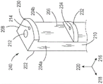
In some embodiments, the commissural support posts can be provided with one or more protrusions that project circumferentially rather than radially. Referring to fig. 6A, a third example of a commissural support post 260 is illustrated. The commissure support posts 260 have a similar structure as the commissure support posts 200 of fig. 4A. For example, the commissure support posts 260 have a radially inner side 266 and a radially outer side 262, the radially inner side 266 facing inwardly toward the centerline of the annular frame, and the radially outer side 262 facing outwardly toward the exterior of the annular frame and, when the prosthetic heart valve is implanted, toward the patient's anatomy. A pair of opposing sides 264a, 264b connect lateral side 262 to medial side 266 at their respective edges.
However, instead of the protrusion 230 protruding inward in the radial direction 216, the first end portion 268 of the commissure support posts 260 includes side protrusions 280a, 280b that protrude away from the respective sides 264a, 264b of the commissure support posts 260 in the circumferential direction 218. At a second portion 270, distal from the first end portion 268, the commissure support posts 260 do not include any protrusions. In some embodiments, the commissure support posts 260 can have one or more longitudinally extending internal lumens 272, the internal lumens 272 being disposed at circumferentially spaced locations between the protrusions 280a, 280 b. For example, when the commissure support posts 260 are part of the actuator 80 of the ring frame 12, the interior lumens 272 can be actuation lumens or locking lumens.
Although fig. 6A illustrates specific locations of the side projections 280a, 280b coinciding with the ends of the commissure support posts 260, in some embodiments, the side projections 280a, 280b can be located at other locations along the length of the commissure support posts 260 such that the commissure support posts 260 extend above and below the side projections 280a, 280b in the longitudinal direction 220. In such an embodiment, the upper surfaces of the side projections 280a, 280b will not coincide with or be coplanar with the upper surfaces of the commissure support posts 260; however, each side projection 280a, 280b will be disposed closer to the first end portion 268 than the second portion 270.
In some embodiments, each side projection 280a, 280b includes at least one aperture or through-hole 274 through which a suture or other attachment member can pass. In the illustrated embodiment of fig. 6A-6B, each side projection 280a, 280B is provided with a plurality of apertures 274, each configured to receive a passage therethrough of a respective suture or other attachment member. Although each aperture 274 is shown in fig. 6A as extending in the longitudinal direction 220 with openings at the top and bottom surfaces of the respective side projections 280a, 280b, in some embodiments, each aperture 274 can alternatively extend in the radial direction 216 with openings at the radially inner and outer surfaces of the respective side projections 280a, 280 b.
As illustrated in fig. 6B, the commissure tab assembly 228 can be coupled to the commissure support post 260 between the first end portion 268 and the second portion 270. The construction of the commissure lug assembly 228 and its assembly with the commissure support posts 260 can be similar to that described above with respect to fig. 4B. For example, the free ends of the lug portions 224a, 224b of the commissure lug assemblies 228 can be flared in the circumferential direction 218 and then wrapped around at least the inner and circumferential sides 266, 264a, 264b of the commissure support posts 260. The free ends of lug portions 224a, 224B can be attached to one another using sutures, as shown in fig. 3B-3C. The edge of lug portion 224a can be disposed adjacent to and optionally in contact with the bottom surface of side projection 280a, while the edge of lug portion 224b can be disposed adjacent to and optionally in contact with the bottom surface of side projection 280 a. The lateral projections 280a, 280b thus restrict the commissure tab assembly 228 (and thus the leaflets 222a, 222b) from moving in the longitudinal direction 220 toward the first end portion 268.
In some embodiments, such as illustrated in FIG. 6B, one or more sutures 276 may extend through the aperture 274 of each side projection 280a, 280B and the corresponding portion of the commissure tab assembly 228 to secure the commissure tab assembly 228 to the projections 280a, 280B. For example, the suture 276 can be threaded through the commissure tab assemblies 228 at portions that contact the respective sides 264a, 264b of the commissure support posts 260. The sutures 276 are thus able to prevent, or at least limit, rotation of the commissure tab assemblies 228 about the commissure support posts 260, thereby maintaining the central alignment of the leaflet assembly within the annular frame 12.
In some embodiments, the commissural posts may be provided with one or more additional lateral protrusions at the opposite axial ends of the commissural tab assembly to further limit the movement of the commissural tab assembly in the longitudinal direction. Referring to fig. 7A, a fourth example of a commissural support post 290 is illustrated. The commissural support post 290 has a similar structure to the commissural support post 260 of fig. 6A, but the commissural support post 290 is provided with at least one additional pair of side tabs 282a, 282b axially spaced from the side tabs 280a, 280b, such as at the second portion 270 of the post. In the embodiment illustrated in fig. 7A, each side projection 280a, 280b, 282a, 282b projects away from the respective side 264a, 264b of the commissure support posts 290 in the circumferential direction 218.
In some embodiments, each side projection 280a, 280b includes at least one aperture or through hole 274 through which a suture or other attachment member can pass, and each side projection 282a, 282b includes at least one aperture or through hole 284 through which a suture or other attachment member can pass. In the illustrated embodiment of fig. 7A-7B, each side projection 280a, 280B is provided with a plurality of apertures 274, each aperture 274 configured to receive a passage therethrough of a respective suture or other attachment member, and each side projection 282a, 282B is provided with a plurality of apertures 284, each aperture configured to receive a passage therethrough of a respective suture or other attachment member. Although each aperture 274, 284 is shown in fig. 7A as extending in the longitudinal direction 220 with openings in the top and bottom surfaces of the respective side projections 280a, 280b, 282a, 282b, in some embodiments, each aperture 274, 284 can alternatively extend in the radial direction 216 with openings in the radially inner and radially-outer surfaces of the respective side projections 280a, 280b, 282a, 282 b.
As illustrated in fig. 7B, the commissure tab assembly 228 can be coupled to the commissure support post 290 between the first end portion 268 and the second portion 270, particularly between the side projections 280a, 280B at one end and the side projections 282a, 282B at the other end. The construction of the commissure lug assemblies 228 and their assembly with the commissure support posts 290 can be similar to that described above with respect to figure 4B. For example, the free ends of the lug portions 224a, 224b of the commissure lug assemblies 228 can be flared in the circumferential direction 218 and then wrapped around at least the inner and circumferential sides 266, 264a, 264b of the commissure support posts 290. The free ends of tab portions 224a, 224B can be attached to one another using sutures, as shown in figures 3B-3C.
The edge of lug portion 224a can be disposed adjacent to and optionally in contact with the bottom surface of side projection 280a, while the edge of lug portion 224b can be disposed adjacent to and optionally in contact with the bottom surface of side projection 280 b. Similarly, the opposite edge of lug portion 224a can be disposed adjacent to and optionally in contact with the top surface of side projection 282a, while the opposite edge of lug portion 224b can be disposed adjacent to and optionally in contact with the top surface of side projection 282 b. Thus, the lateral projections 280a, 280b restrict the commissure tab assembly 228 (and thus the leaflets 222a, 222b) from moving in the longitudinal direction 220 toward the first end portion 268, while the lateral projections 282a, 282b restrict the commissure tab assembly 228 (and thus the leaflets 222a, 22b) from moving in the longitudinal direction 220 toward the second portion 270.
In some embodiments, as shown in FIG. 7B, one or more sutures 276 can extend through the aperture 274 of each side projection 280a, 280B and the corresponding portion of the commissure tab assembly 228 to secure the commissure tab assembly 228 to the projections 280a, 280B. Alternatively or additionally, one or more sutures 286 can extend through the apertures 284 of the side projections 282a, 282b and corresponding portions of the commissure tab assembly 228 to secure the commissure tab assembly 228 to the projections 282a, 282 b. For example, the sutures 276, 286 can be threaded through the commissure tab assemblies 228 at portions that contact the respective sides 264a, 264b of the commissure support posts 290. The sutures 276, 286 can thus prevent, or at least limit, rotation of the commissure tab assembly 228 about the commissure support posts 290, thereby maintaining the leaflet assembly in central alignment within the annular frame 12.
In some embodiments, one or more protrusions of the commissure support posts can form slots or recessed slots through which sutures can pass, rather than through holes or apertures. Referring to fig. 8A, a fifth example of such a commissural support post 300 is illustrated. The commissure support posts 300 have a similar structure as the commissure support posts 260 of figure 6A. For example, the commissure support posts 300 have a radially inner side 306 and a radially outer side 302, the radially inner side 306 facing inwardly toward the centerline of the annular frame, and the radially outer side 302 facing outwardly toward the exterior of the annular frame and toward the patient's anatomy when the prosthetic heart valve is implanted. A pair of opposing sides 304a, 304b connect lateral side 302 to medial side 306 at their respective edges.
However, instead of the side projections 280a, 280b having respective apertures 274, the first end portion 308 of the commissure support posts 300 includes side projections 314a, 314b without any apertures. Rather, each side projection 314a, 314b includes a respective narrow width neck portion 316a, 316b and a larger width end portion 318a, 318 b. Each side protrusion 314a, 314b protrudes in the circumferential direction 218 away from the respective side 304a, 304b of the commissure support posts 300. Thus, a pair of radially extending slots 320a, 320b separated from each other by a neck portion 316a are formed between the protrusion 314a and the sides 304a of the commissural supports 300 (e.g., the central portion of the commissural supports 300). Similarly, a pair of radially extending slots 320c, 320d separated from each other by a neck portion 316b are formed between the protrusion 314b and the side 304b of the commissural support 300 (e.g., a central portion of the commissural support 300). Alternatively, each end portion 318a, 318b can be arranged 316a, 316b relative to the neck portion such that only a single slot is formed between the protrusions 314a, 314b and the respective side 304a, 304b of the commissure support posts 300.
At a second end portion 310 distal from the first end portion 308, the commissural support posts 300 do not include any protrusions. In some embodiments, the commissural support posts 300 can have one or more longitudinally extending internal lumens 312 disposed at circumferentially spaced locations between the protuberances 314a, 314 b. For example, when the commissure support posts 300 are part of the actuator 80 of the ring frame 12, the interior lumen 312 can be an actuation lumen or a locking lumen.
Although fig. 8A illustrates specific locations of the side projections 314a, 314b coincident with the ends of the commissure support posts 300, in some embodiments, the side projections 314a, 314b can be located at other locations along the length of the commissure support posts 300, such that the commissure support posts 300 extend above and below the side projections 314a, 314b in the longitudinal direction 220. In such an embodiment, the upper surfaces of the side projections 314a, 314b will not coincide with or be coplanar with the upper surfaces of the commissure support posts 300; however, each side projection 314a, 314b will be disposed closer to the first end portion 308 than the second end portion 310.
As illustrated in fig. 8B, the commissure lug assembly 228 can be coupled to the commissure support post 300 between a first end portion 308 and a second end portion 310. The construction of the commissure lug assembly 228 and its assembly with the commissure support post 300 can be similar to that described above with respect to fig. 4B. For example, the free ends of the lug portions 224a, 224b of the commissure lug assemblies 228 can be flared in the circumferential direction 218 and then wrapped around at least the inner side 306 and circumferential sides 304a, 304b of the commissure support post 300. The free ends of tab portions 224a, 224B can be attached to one another using sutures, as shown in figures 3B-3C. The edge of lug portion 224a can be disposed adjacent to, and optionally in contact with, the bottom surface of side projection 314a (e.g., neck portion 316a), while the edge of lug portion 224b can be disposed adjacent to, and optionally in contact with, the bottom surface of side projection 314b (e.g., neck portion 316 b). The lateral projections 314a, 314b thus restrict the commissure tab assembly 228 (and thus the leaflets 222a, 222b) from moving in the longitudinal direction 220 toward the first end portion 308.
In some embodiments, as illustrated in fig. 8B, one or more sutures 322 can extend through the slots formed by each side projection 314a, 314B and can be wrapped at least partially around the respective neck portion 316a, 316B to secure the commissure tab assemblies 228 to the projections 314a, 314B. For example, the suture 322 can extend through the slot 320a, wrap over the neck portion 316a, extend through the slot 320b, and pass through the leaflet tabs 224a that contact the sides 304a of the commissural support post 300. Similarly, another suture 322 (or the same suture, not shown) can extend through the slot 320c, wrap over the neck portion 316b, extend through the slot 320d, and pass through the leaflet tabs 224b that contact the sides 304b of the commissural support post 300. The sutures 322 are thus able to prevent, or at least limit, rotation of the commissure tab assemblies 228 about the commissure support posts 300, thereby maintaining the leaflet assembly's centered alignment within the annular frame 12.
In some embodiments, the commissural posts may be provided with one or more additional lateral protrusions at the opposite axial ends of the commissural tab assembly to further limit the movement of the commissural tab assembly in the longitudinal direction. Referring to fig. 9A, a sixth example of a commissural support post 330 is illustrated. The commissural support posts 330 have a similar structure to the commissural support posts 300 of fig. 8A, but have at least one additional pair of lateral protrusions 334a, 334b at their second end portions 310.
Each side projection 334a, 334b includes a respective narrow width neck portion and a larger width end portion 338a, 338b and is spaced apart from the respective side 304a, 304b of the commissure support post 330 (e.g., a central portion of the commissure support post 330) in the circumferential direction 218. Thus, another pair of radially extending slots 340a, 340b separated from each other by a neck portion 336a are formed between the protrusion 334a and the sides 304a of the commissure support posts 330 (e.g., a central portion of the commissure support posts 330). Similarly, a pair of radially extending slots (only 340d visible in fig. 9A) separated from each other by a neck portion (not visible in fig. 9A-9B) are formed between the protrusion 334B and the side 304B of the commissure support posts 330 (e.g., a central portion of the commissure support posts 330). Alternatively, each end portion 338a, 338b can be arranged relative to a respective neck portion such that only a single slot is formed between the protrusions 334a, 334b and the respective side 304a, 304b of the commissure support posts 330.
As illustrated in fig. 9B, the commissure lug assembly 228 can be coupled to the commissure support posts 330 between the first end portion 308 and the second end portion 310, particularly between the side projections 314a, 314B at one end and the side projections 334a, 334B at the other end. The construction of the commissure lug assembly 228 and its assembly with the commissure support posts 330 can be similar to that described above with respect to fig. 4B. For example, the free ends of the lug portions 224a, 224b of the commissure lug assemblies 228 can be flared in the circumferential direction 218 and then wrapped around at least the inner side 306 and circumferential sides 304a, 304b of the commissure support posts 330. The free ends of tab portions 224a, 224B can be attached to one another using sutures, as shown in figures 3B-3C.
The edge of lug portion 224a can be disposed adjacent to and optionally in contact with the bottom surface of side projection 314a (e.g., neck portion 316a), while the edge of lug portion 224b can be disposed adjacent to and optionally in contact with the bottom surface of side projection 314b (e.g., neck portion 316 b). Similarly, the opposite edge of lug portion 224a can be disposed adjacent to and optionally in contact with the top surface of side projection 334a (e.g., neck portion 336a), while the opposite edge of lug portion 224b can be disposed adjacent to and optionally in contact with the top surface of side projection 334b (e.g., neck portion between end portion 338b and side 304 b). Thus, the lateral projections 314a, 314b restrict the commissure tab assemblies 228 (and thus the leaflets 222a, 222b) from moving in the longitudinal direction 220 toward the first end portion 308, while the lateral projections 334a, 334b restrict the commissure tab assemblies 228 (and thus the leaflets 222a, 222b) from moving in the longitudinal direction 220 toward the second end portion 310.
As discussed above with respect to FIG. 8B, one or more sutures 322 may extend through the slots 320a-320d formed by the side projections 314a, 314B to secure the commissure tab assemblies thereto. In some embodiments, such as illustrated in fig. 9B, one or more sutures 342 can extend through the slots formed by each side projection 334a, 334B and can be wrapped at least partially around the respective neck portion to secure the commissure tab assembly 228 to the projections 334a, 334B. For example, the suture 342 can extend through the radially outer side slot 340a, wrap under the neck portion 336a, extend through the radially inner side slot 340b, and pass through the leaflet tabs 224a that contact the side 304a of the commissure support post 330. Similarly, another suture (or the same suture 342) can extend through the radially outer side slot, wrap under the neck portion (between end portion 338b and side 304 b), extend through the radially inner side slot 320d, and pass through the leaflet tab 224b, which contacts the side 304b of the commissure support post 330. The suture 342 can thus further prevent, or at least further limit, rotation of the commissure tab assembly 228 about the commissure support post 330, thereby maintaining the leaflet assembly in central alignment within the annular frame 12.
In some embodiments, the commissural supports can be provided with one or more protrusions that form circumferentially extending slots rather than radially extending slots and that protrude radially rather than circumferentially. Referring to fig. 10A, a seventh example of a commissural support post 350 is illustrated. The commissure support posts 350 have a similar structure as the commissure support posts 300 of figure 8A. For example, the commissure support posts 350 have a radially inner side 356 and a radially outer side 352, the radially inner side 356 facing inwardly toward the centerline of the ring frame, and the radially outer side 352 facing outwardly toward the exterior of the ring frame and toward the patient's anatomy when the prosthesis is installed. The heart valve is implanted. A pair of opposing sides 354a, 354b connect lateral side 352 to medial side 356 at their respective edges.
However, instead of the circumferentially projecting tabs 314a, 314b, the first end portion 358 of the commissure support posts 350 includes a tab 364 that projects inwardly in the radial direction 216 and away from the inner side surface 356 of the commissure support posts 350. At a second portion 360 distal from the first end portion 358, the commissure support posts 350 do not include any protrusions. In some embodiments, the commissure support posts 350 can have one or more longitudinally extending inner lumens 362, the inner lumens 362 being disposed at a location spaced radially outward from the projections 364. For example, when the commissure support posts 350 are part of the actuator 80 of the ring frame 12, the interior lumen 362 can be an actuation lumen or a locking lumen.
The protrusion 364 includes a narrower width neck portion 366 and a larger width end portion 368 and projects away from the inner side 356 of the commissure support post 350 along the radial direction 216. Thus, a pair of circumferentially extending slots 370a, 370b separated from one another by the neck portion 366 are formed between the protrusion 364 and the side 356 of the commissure support post 350 (e.g., a central portion of the commissure support post 350). Alternatively, the end portion 368 can be disposed relative to the neck portion 366 such that only a single slot is formed between the protrusion 364 and the side 356 of the commissure support posts 350.
Although fig. 10A illustrates a particular location of the protrusion 364 coinciding with the end of the commissure support posts 350, in some embodiments, the protrusion 364 can be located at other locations along the length of the commissure support posts 350 such that the commissure support posts 350 extend above and below the protrusion 364 in the longitudinal direction 220. In such an embodiment, the upper surface of the protrusion 364 will not coincide with or be coplanar with the upper surface of the commissure support posts 350; however, the protrusion 364 will be disposed closer to the first end portion 358 than the second portion 360.
As illustrated in fig. 10B, the commissure tab assembly 228 can be coupled to the commissure support post 350 between the first and second portions 358, 360. The construction of the commissure lug assembly 228 and its assembly with the commissure support posts 350 may be similar to that described above with respect to fig. 4A. For example, the free ends of the lug portions 224a, 224b of the commissure lug assemblies 228 can be flared in the circumferential direction 218 and then wrapped around at least the inner and circumferential sides 356, 354a, 354b of the commissure support posts 350. The free ends of tab portions 224a, 224B can be attached to one another using sutures, as shown in figures 3B-3C. The edges of the leaflets 222a, 222b can be disposed adjacent to, and optionally in contact with, the bottom surface (e.g., neck portion 366 and/or end portion 368) of the projection 364. The protrusions 364 thus restrict the commissure tab assembly 228 (and thus the leaflets 222a, 222b) from moving in the longitudinal direction 220 toward the first end portion 358.
In some embodiments, such as illustrated in fig. 10B, one or more sutures 372 can extend through the slots formed by the protrusions 364 and can be wrapped at least partially around the neck portion 366 to secure the commissure tab assembly 228 to the protrusions 364. For example, the suture 372 can extend through the left slot 370a, wrap over the neck portion 366, extend through the right slot 370b, and pass through portions of the commissure tab assembly 228. For example, the suture 372 can be threaded through the commissure tab assembly 228 at the portion where the optional reinforcement member is disposed, at the portion of the leaflet tab portions 224a, 224b that face or contact the inner surface 356, or at any other location along the commissures. The sutures 372 can thus prevent, or at least limit, rotation of the commissure tab assemblies 228 about the commissure support posts 350, thereby maintaining the leaflet assembly in central alignment within the annular frame 12.
In some embodiments, the commissure support posts can be provided with one or more additional protrusions at the opposite axial ends of the commissure tab assemblies to further limit movement of the commissure tab assemblies in the longitudinal direction. Referring to fig. 11A, an eighth example of a commissural support post 380 is illustrated. The commissure support posts 380 have a similar structure as the commissure support posts 350 of fig. 10A, but the commissure support posts 380 have at least one additional protrusion 382 axially spaced from the protrusion 364, such as at the second portion 360 of the post. The additional projection 382 includes a narrower width neck portion 384 and a larger width end portion 386, and projects inwardly in the radial direction 216 and away from the inner side surface 356 of the commissure support posts 380. Thus, another pair of circumferentially extending slots 388a, 388b, separated from one another by a neck portion 384, are formed between the projection 382 and the side surface 356 of the commissure support post 380 (e.g., a central portion of the commissure support post 380). Alternatively, the end portion 386 can be disposed relative to the neck portion 384 such that only a single slot is formed between the projection 382 and the inner side surface 356 of the commissure support posts 380.
As illustrated in fig. 11B, the commissure lug assembly 228 can be coupled to the commissure support posts 380 between the first end portion 358 and the second portion 360, particularly between the protrusions 364 at one end and the protrusions 382 at the other end. The construction of the commissure lug assembly 228 and its assembly with the commissure support posts 330 can be similar to that described above with respect to fig. 4B. For example, the free ends of the lug portions 224a, 224b of the commissure lug assemblies 228 can be flared in the circumferential direction 218 and then wrapped around at least the inner and circumferential sides 356, 354a, 354b of the commissure support posts 380. The free ends of tab portions 224a, 224B can be attached to one another using sutures, as shown in figures 3B-3C. The edges of the leaflets 222a, 222b can be disposed adjacent to, and optionally in contact with, the bottom surface (e.g., neck portion 366 and/or end portion 368) of the projection 364. Similarly, the opposing edges of the leaflets 222a, 222b can be disposed adjacent to, and optionally in contact with, the top surface of the projection 382 (e.g., neck portion 384 and/or end portion 386). Thus, the protrusions 364 restrict the commissure tab assembly 228 (and thus the leaflets 222a, 222b) from moving in the longitudinal direction 220 toward the first end portion 358, while the protrusions 382 restrict the commissure tab assembly 228 (and thus the leaflets 222a, 222b) from moving in the longitudinal direction 220 toward the second portion 360.
One or more sutures 372 can extend through the slots 370a, 370b formed by the protrusions 364 and can be wrapped at least partially around the neck portion 366 to secure the clutch lug assembly 228 to the protrusions 364. Alternatively or additionally, one or more sutures 390 can extend through slots 388a, 388b formed by the projection 382 and can be wrapped at least partially around the neck portion 384 to secure the commissure tab assembly 228 to the projection 382. For example, the suture 390 can extend through the left slot 388a, wrap under the neck portion 384, extend through the right slot 388b, and pass through portions of the commissure tab assembly 228. For example, the suture 390 can pass through the commissure tab assembly 228 at the portion where the optional reinforcement member is disposed, at the portion of the leaflet tab portions 224a, 224b facing or contacting the inner surface 356, or at any other location along the commissures. The sutures 372, 390 thus can prevent, or at least limit, rotation of the commissure tab assemblies 228 about the commissure support posts 380, thereby maintaining the central alignment of the leaflet assembly within the annular frame 12.
Although specific shapes and configurations of the commissure support posts have been illustrated in the figures and described in the above examples, embodiments of the disclosed subject matter are not so limited. Indeed, in some embodiments, the commissural support posts may have a cross-sectional geometry (e.g., in a plane perpendicular to the longitudinal axis of the ring frame) that is circular, elliptical, hexagonal, octagonal, or any other shape. However, in some embodiments, it may be preferred that the corners and/or edges of the commissural support posts be rounded (e.g., with a radius) or chamfered, e.g., to avoid catching or tearing of sutures or leaflets. Moreover, while particular shapes and configurations of the projections of the commissure support posts have been illustrated in the figures and described in the examples above, different shapes and/or configurations are possible according to one or more contemplated embodiments. For example, the width of the radially extending protrusions in the circumferential direction can be less than the width of the commissure support posts, and/or the width of the circumferentially extending protrusions in the radial direction can be less than the width of the commissure support posts. The size and shape of each commissure support post and the projections thereon can take into account any desired clearance, particularly when the heart valve is in a fully collapsed or crimped state, e.g., to allow for a minimized cross-sectional diameter heart valve, for implantation within a patient and/or to avoid interfering with the operation of various components of the valve, such as the operation of the leaflets once implanted.
Although a particular number of protuberances for the commissure support posts have been illustrated in the figures and described in the examples above, fewer or additional protuberances may be included in the commissure support posts in embodiments of the disclosed subject matter. For example, a commissural support post with multiple circumferentially extending projections can alternatively have a single circumferentially extending projection. In another example, the single radially extending protrusion of the commissure support posts can be replaced by a plurality of radially extending protrusions with radially extending gaps therebetween. In yet another example, a single circumferentially extending protrusion at one or both sides of a commissural support post can be replaced by a plurality of circumferentially extending protrusions, with circumferentially extending gaps between them.
Although specific numbers, sizes, and shapes of apertures and slots have been illustrated in the figures and described in the examples above, other numbers, sizes, and/or shapes are possible in accordance with one or more contemplated embodiments. For example, multiple apertures in the protrusion can be combined together to form a single larger aperture or slot. Typically, the aperture is sized to allow a needle carrying a suture to pass therethrough. Conversely, because the slot remains open at one end, the width of the slot can be based on the cross-sectional dimension of the suture passing therethrough rather than on the needle, which has a diameter greater than the cross-sectional dimension of the suture.
In some embodiments, features illustrated separately in different figures or described above as separate examples can still be combined together. For example, in some embodiments, the commissure support posts can have a radially extending protrusion and a circumferentially extending protrusion at the same end. Alternatively or additionally, the commissure support posts can have one type of protrusion (e.g., a radially extending protrusion) at a first end and a different type of protrusion (e.g., a pair of circumferentially extending protrusions) at a second end. In some embodiments, the projections of the commissure support posts can have apertures for passing sutures therethrough, and can also have narrow neck portions for forming slots for passing the same or different sutures therethrough. In some embodiments, the radially and circumferentially extending projections at the same end of the commissure support posts can be combined together in a single continuous geometry (e.g., the cross-sectional shape of the commissure support posts is entirely contained within the cross-sectional shape of the single projection in plan view).
In some embodiments, the size of the protrusion can be reduced or eliminated altogether, facilitating an aperture formed directly in the body of the commissure support posts. For example, the commissural support posts may include holes or apertures that extend across the entire radial or circumferential width of the post. One or more sutures can then be passed through the apertures to secure the commissure tab assemblies in place on the commissure support posts. However, in embodiments where the commissure support posts may be part of a locking or actuator assembly, such through-holes should be positioned to avoid interfering with the locking or actuation mechanism (e.g., by avoiding the internal lumen 212 in fig. 4A). Alternatively or additionally, the commissure support posts may include a curved internal path with a first opening on an exposed upper surface of the post and a second opening on a radially inner or circumferential sidewall. The suture may extend through the internal passageway and through the commissure tab assembly to secure the assembly in place on the post.
Additional description of related embodiments
Clause 1. a prosthetic heart valve, comprising:
an annular frame radially collapsible and expandable between a radially compressed configuration and a radially expanded configuration, the annular frame having an inflow end and an outflow end separated from the inflow end along an axial direction of the frame, the annular frame comprising a plurality of commissure support posts; and
a valve structure supported within the annular frame and including a plurality of leaflets, each leaflet having a pair of tabs, the tabs of adjacent leaflets mating together to form a commissure tab assembly,
where there is one commissure support post for each commissure lug assembly,
each commissure tab assembly coupled to a corresponding commissure support post, one tab at least partially wrapped around the commissure support post in a first direction and the other tab at least partially wrapped around the commissure support post in a second direction,
each commissure support post having a first portion with a pair of first protrusions protruding in opposite directions in a circumferential direction of the ring frame,
for each commissure support post, the corresponding commissure lug assembly disposed between the first portion and the inflow end of the annular frame in the axial direction,
for each commissure support post, the pair of first projections are arranged in the axial direction to limit axial movement of the respective commissure lug assembly in a downstream direction.
Clause 2. the prosthetic heart valve of clause 1, wherein for each commissure support post, the first portion is the end portion thereof closest to the outflow end of the annular frame.
Clause 3. the prosthetic heart valve of any of clauses 1-2, wherein each commissure post has a second portion with a pair of second protrusions that project in opposite directions along the circumferential direction of the annular frame.
The prosthetic heart valve of claim 3, wherein for each commissure support post, the corresponding commissure tab assembly is disposed between the first portion and the second portion in the axial direction, and the pair of second protrusions is disposed in the axial direction so as to limit axial movement of the respective commissure tab assembly in an upstream direction.
Clause 5. the prosthetic heart valve of any of clauses 3-4, wherein for each commissure support post, the second portion is between the first portion and an end portion of the commissure support post closest to the inflow end of the annular frame.
Clause 6. the prosthetic heart valve of any of clauses 3-5, wherein for each commissure support post, each second protrusion includes at least one aperture, and the tab of the corresponding commissure tab assembly is coupled to the seam support post via one or more sutures that pass through the apertures of the pair of second protrusions.
Clause 7. the prosthetic heart valve of clause 6, wherein for each second projection, each aperture is a hole or opening that extends through a thickness of the respective second projection along the axial direction.
Clause 8. the prosthetic heart valve of any of clauses 1-7, wherein for each commissure support post, each first protrusion includes at least one aperture, and the tab of the corresponding commissure tab assembly is coupled to the seam support post via one or more sutures that pass through the apertures of the pair of first protrusions.
Clause 9. the prosthetic heart valve of clause 8, wherein for each first projection, each aperture is a hole or opening that extends through a thickness of the respective first projection along the axial direction.
an annular frame radially collapsible and expandable between a radially compressed configuration and a radially expanded configuration, the annular frame having an inflow end and an outflow end separated from the inflow end along an axial direction of the frame, the annular frame comprising a plurality of commissure support posts; and
a valve structure supported within the annular frame and including a plurality of leaflets, each leaflet having a pair of tabs, the tabs of adjacent leaflets mating together to form a commissure tab assembly,
with one commissure support post per commissure lug assembly,
each commissure tab assembly coupled to the corresponding commissure support post, one tab at least partially wrapped around the commissure support post in a first direction and the other tab at least partially wrapped around the commissure support post in a second direction,
each commissure support post having a first portion with a pair of first protrusions protruding toward an interior of the ring frame in a circumferential direction of the ring frame,
for each commissure support post, the corresponding commissure lug assembly disposed between the first portion and the inflow end of the annular frame in the axial direction,
for each commissure support post, the first projection is arranged in the axial direction so as to limit axial movement of the respective commissure lug assembly in a downstream direction.
Clause 11 the prosthetic heart valve of clause 10, wherein for each commissure support post, the first portion is the end portion thereof closest to the outflow end of the annular frame.
The prosthetic heart valve of clause 13, where, for each commissure support post, the corresponding commissure tab assembly is disposed between the first portion and the second portion in the axial direction, and the second protrusion is disposed in the axial direction so as to limit axial movement of the corresponding commissure tab assembly in an upstream direction.
Clause 15 the prosthetic heart valve of any of clauses 12-14, wherein for each commissure support post, the second protrusion comprises at least one aperture, and the tab of the corresponding commissure tab assembly is coupled to the commissure support post via one or more sutures passing through the at least one aperture of the second protrusion.
The prosthetic heart valve of clause 17. the prosthetic heart valve of clause 10-16, wherein, for each commissure support post, the first projection comprises at least one aperture, and the tab of the corresponding commissure tab assembly is coupled to the commissure support post via one or more sutures that pass through the at least one aperture of the first projection.
Clause 19. a prosthetic heart valve, comprising:
an annular frame radially collapsible and expandable between a radially compressed configuration and a radially expanded configuration, the annular frame having an inflow end and an outflow end separated from the inflow end along an axial direction of the frame, the annular frame comprising a plurality of commissure support posts; and
a valve structure supported within the annular frame and including a plurality of leaflets, each leaflet having a pair of tabs, the tabs of adjacent leaflets mating together to form a commissure tab assembly,
with one commissure support post per commissure lug assembly,
each commissure tab assembly coupled to the corresponding commissure support post, one tab at least partially wrapped around the commissure support post in a first direction and the other tab at least partially wrapped around the commissure support post in a second direction,
each commissure support post having a first portion with a pair of first projections projecting in opposite directions in a circumferential direction of the annular frame, each first projection having a neck portion with a first width and an end portion with a second width greater than the first width, the neck portion being disposed in the circumferential direction between the end portion and a central portion of the first portion of the respective commissure support post such that at least one slot is formed between a surface of the central portion and a facing surface of the end portion,
for each commissure support post, the corresponding commissure lug assembly disposed between the first portion and the inflow end of the annular frame in the axial direction, and
for each commissure support post, the pair of first protrusions are arranged in the axial direction so as to limit axial movement of the respective commissure lug assembly in a downstream direction.
Clause 21. the prosthetic heart valve of any one of clauses 19-20, wherein each commissure post has a second portion with a pair of second projections projecting in opposite directions along the circumferential direction of the annular frame, each second projection having a second neck portion with a third width and a second end portion with a fourth width greater than the third width, the second neck portion disposed between the second end portion and a second central portion of the second portion of the respective commissure support post along the circumferential direction such that at least one second slot is formed between a surface of the second central portion and a facing surface of the second end portion.
The prosthetic heart valve of clause 22, wherein for each commissure support post, the corresponding commissure tab assembly is disposed between the first portion and the second portion in the axial direction, and the pair of second protrusions is disposed in the axial direction so as to limit axial movement of the corresponding commissure tab assembly in an upstream direction.
Clause 23. the prosthetic heart valve of any of clauses 21-22, wherein for each commissure support post, the second portion is between the first portion and an end portion of the commissure support post closest to the inflow end of the annular frame.
Clause 25. the prosthetic heart valve of any of clauses 21-24, wherein for each second protrusion, the second neck portion is disposed relative to the corresponding second end portion such that a pair of second slots are formed on opposite sides of the second neck portion.
Clause 27. the prosthetic heart valve of any of clauses 19-26, wherein for each first projection, the neck portion is disposed relative to the corresponding end portion such that a pair of the slots are formed on opposite sides of the neck portion.
an annular frame radially collapsible and expandable between a radially compressed configuration and a radially expanded configuration, the annular frame having an inflow end and an outflow end separated from the inflow end along an axial direction of the frame, the annular frame comprising a plurality of commissure support posts; and
a valve structure supported within the annular frame and including a plurality of leaflets, each leaflet having a pair of tabs, the tabs of adjacent leaflets mating together to form a commissure tab assembly,
with one commissure support post per commissure lug assembly,
each commissure tab assembly coupled to the corresponding commissure support post, one tab at least partially wrapped around the commissure support post in a first direction and the other tab at least partially wrapped around the commissure support post in a second direction,
each commissure support post having a first portion with a pair of first projections projecting in a radial direction of the ring frame toward an interior of the ring frame, each first projection having a neck portion with a first width and an end portion with a second width greater than the first width, the neck portion being disposed in the radial direction between the end portion and a central portion of the first portion of the respective commissure support post such that at least one slot is formed between a surface of the central portion and a facing surface of the end portion,
for each commissure support post, the corresponding commissure lug assembly disposed between the first portion and the inflow end of the annular frame in the axial direction, and
for each commissure support post, the first projection is arranged in an axial direction so as to limit axial movement of the respective commissure lug assembly in a downstream direction.
Clause 29. the prosthetic heart valve of clause 28, wherein for each commissure support post, the first portion is the end portion thereof closest to the outflow end of the annular frame.
The prosthetic heart valve of clause 31, wherein for each commissure support post, the corresponding commissure tab assembly is disposed between the first portion and the second portion in the axial direction, and the second protrusion is disposed in the axial direction so as to limit axial movement of the corresponding commissure tab assembly in an upstream direction.
Clause 32. the prosthetic heart valve of any of clauses 30-31, wherein for each commissure support post, the second portion is between the first portion and an end portion of the commissure support post closest to the inflow end of the annular frame.
Clause 33. the prosthetic heart valve of any of clauses 30-32, wherein for each commissure support post, the tab of the corresponding commissure tab assembly is coupled to the commissure support post via one or more sutures passing through the at least one second slot formed by the second protrusion.
Clause 34. the prosthetic heart valve of any of clauses 30-33, wherein for each second projection, the second neck portion is disposed relative to the corresponding second end portion such that a pair of the second slots are formed on opposite sides of the second neck portion.
The prosthetic heart valve of clause 35. the prosthetic heart valve of clause 28-34, wherein for each commissure support post, the tab of the corresponding commissure tab assembly is coupled to the commissure support post via one or more sutures passing through at least one slot formed by passing through the first protrusion.
Clause 36. the prosthetic heart valve of any of clauses 28-35, wherein for each first projection, the neck portion is disposed relative to the corresponding end portion such that a pair of the slots are formed on opposite sides of the neck portion.
Clause 37. a prosthetic heart valve, comprising:
an annular frame radially collapsible and expandable between a radially compressed configuration and a radially expanded configuration, the annular frame having an inflow end and an outflow end separated from the inflow end along an axial direction of the frame, the annular frame comprising a plurality of commissure support posts; and
a valve structure supported within the annular frame and comprising a plurality of leaflets, each leaflet having a pair of tabs, the tabs of adjacent leaflets mating together to form a commissure tab assembly, each commissure tab assembly coupled to the respective commissure support post,
wherein the annular frame includes a means for limiting axial movement of the commissure lug assembly.
The prosthetic heart valve of clause 38. the prosthetic heart valve of clause 37, wherein each commissure tab assembly is coupled to the corresponding commissure support post, one of the tabs wrapping at least partially around the commissure support post in a first direction and the other tab wrapping at least partially around the commissure support post in a second direction.
Clause 39. the prosthetic heart valve of any of clauses 37-38, wherein the means for limiting axial movement is constructed and arranged to limit axial movement of the commissure tab assembly in the downstream direction, the upstream direction, or both.
Clause 40 the prosthetic heart valve of any one of clauses 37-39, wherein the means for limiting axial movement comprises one or more protrusions protruding from respective central portions of the commissure support posts in a circumferential or radial direction of the annular frame.
Clause 41. the prosthetic heart valve of any of clauses 1-40, wherein the commissure support posts are part of an actuator assembly that actuates the annular frame between the radially compressed configuration and the radially expanded configuration.
Clause 42. the prosthetic heart valve of any of clauses 1-41, wherein: each commissure support post has a first surface facing an interior of the ring frame, a second surface facing an exterior of the ring frame, and opposing side surfaces extending between the first and second surfaces, and portions of a commissure tab assembly wrap around at least the first and side surfaces of the respective commissure support post.
Clause 43. the prosthetic heart valve of any of clauses 1-42, wherein the valve structure is a mitral valve structure with two leaflets and two commissure tab assemblies, and the valve structure is coupled to the annular frame via the commissure tab assemblies on diametrically opposite sides of the annular frame from each other.
Clause 44. the prosthetic heart valve of any of clauses 1-42, wherein the valve structure is a tricuspid valve structure having three leaflets and three commissure tab assemblies, and the valve structure is coupled to the annular frame via the three commissure tab assemblies equally spaced along a circumferential direction of the annular frame.
Clause 45. the prosthetic heart valve of any of clauses 1-44, wherein the annular frame is formed of a plastically-expandable material or a self-expanding material.
Clause 46. the prosthetic heart valve of any of clauses 1-45, wherein the annular frame comprises an array of angled struts articulated together by one or more pivots.
Clause 47. the prosthetic heart valve of any of clauses 1-46, wherein the prosthetic heart valve is configured for implantation in an existing heart valve in a patient.
Clause 48. the prosthetic heart valve of any of clauses 1-47, wherein the prosthetic heart valve is configured for implantation at an aortic position or a mitral position.
Clause 49. an assembly, comprising:
a delivery device comprising an elongate shaft; and
the prosthetic heart valve of any of clauses 1-48 is mounted on the elongate shaft in a radially compressed configuration for delivery into a patient.
Clause 50. a method of implanting a prosthetic heart valve in a patient, the method comprising:
inserting a distal end of a delivery device into a vasculature of a patient, the delivery device comprising an elongate shaft, the prosthetic heart valve according to any of clauses 1-48 releasably mounted on the elongate shaft of the delivery device in a radially compressed configuration;
advancing the prosthetic heart valve to a desired implantation site; and
expanding the prosthetic heart valve to the radially expanded configuration using the delivery device to implant the prosthetic heart valve at a desired implantation site.
Clause 51. a method of implanting a prosthetic heart valve in a patient, the method comprising:
inserting a distal end of a delivery device into a vasculature of a patient, the delivery device comprising an elongate shaft, the prosthetic heart valve according to any of clauses 1-48 releasably mounted on the elongate shaft of the delivery device in a radially compressed configuration;
advancing the prosthetic heart valve to a desired implantation site; and
deploying the prosthetic heart valve from the delivery device such that the prosthetic heart valve self-expands to the radially expanded configuration, thereby implanting the prosthetic heart valve at a desired implantation site.
Clause 52. the method of any one of clauses 50-51, wherein the advancing to the desired implantation site is in a transfemoral, transventricular, transapical, or transseptal manner.
Clause 53. a method of assembling a prosthetic heart valve, comprising:
disposing commissure tab assemblies of leaflets of a valve structure on respective commissure support posts of an annular frame, the annular frame being radially collapsible and expandable between a radially compressed configuration and a radially expanded configuration, the annular frame having an inflow end and an outflow end spaced from the inflow end in an axial direction of the frame, the annular frame including a plurality of commissure support posts, each commissure tab assembly having one commissure support post, the valve structure including a plurality of leaflets, each leaflet having a pair of tabs, each commissure tab assembly being formed by a pair of tabs of adjacent leaflets; and
coupling each commissure lug assembly to its respective commissure support post,
wherein each commissural support post has a first portion with a pair of first protrusions protruding in opposite directions in a circumferential direction of the ring frame,
wherein for each commissure support post, the corresponding commissure lug assembly is disposed between the first portion and the inflow end of the annular frame in the axial direction,
wherein for each commissure support post, the pair of first protrusions are arranged along the axial direction so as to limit axial movement of the respective commissure lug assemblies in a downstream direction, an
Wherein the arrangement comprises:
wrapping a leaflet tab of the commissure tab assembly at least partially around the respective commissure support column in a first direction; and
wrapping the other leaflet tab of the commissure tab assembly at least partially around the respective commissure support post in a second direction.
Clause 54. the method of clause 53, wherein for each commissure support post, the first portion is the end portion thereof closest to the outflow end of the annular frame.
Clause 55. the method of any one of clauses 53-54, wherein each commissure post has a second portion with a pair of second protrusions that project in opposite directions along the circumferential direction of the ring frame.
Clause 56. the method of clause 55, wherein disposing the commissure tab assemblies on the respective commissure posts comprises: for each commissure support post, providing the respective commissure tab assembly between the first portion and the second portion along the axial direction, and for each commissure support post, the pair of second protrusions are arranged along the axial direction so as to limit axial movement of the respective commissure tab assembly in an upstream direction.
Clause 57. the method of any of clauses 55-56, wherein for each commissure support post, the second portion is between the first portion and an end portion of the commissure support post closest to the inflow end of the annular frame.
Clause 58. the method of any one of clauses 55-57, wherein: for each commissure support post, each second projection includes at least one aperture, and coupling each commissure tab assembly to its respective commissure support post includes, for each commissure support post, passing one or more sutures through the apertures of the pair of second projections.
Clause 59. the method of clause 58, wherein for each second protrusion, each aperture is a hole or opening that extends through a thickness of the respective second protrusion along the axial direction.
Clause 60. the method of any one of clauses 53-59, wherein: for each commissure support post, each first projection includes at least one aperture, and coupling each commissure tab assembly to its respective commissure support post includes, for each commissure support post, passing one or more sutures through the apertures of the pair of first projections.
Clause 61. the method of clause 60, wherein for each first protrusion, each aperture is a hole or opening extending through a thickness of the respective first protrusion in the axial direction.
Clause 62. a method of assembling a prosthetic heart valve, comprising:
disposing commissure tab assemblies of leaflets of a valve structure on respective commissure support posts of an annular frame, the annular frame being radially collapsible and expandable between a radially compressed configuration and a radially expanded configuration, the annular frame having an inflow end and an outflow end spaced from the inflow end in an axial direction of the frame, the annular frame including a plurality of commissure support posts, each commissure tab assembly having one commissure support post, the valve structure including a plurality of leaflets, each leaflet having a pair of tabs, each commissure tab assembly being formed by a pair of tabs of adjacent leaflets; and
coupling each commissure lug assembly to its respective commissure support post,
wherein each commissural support post has a first portion with a first protrusion that protrudes in a radial direction of the ring frame towards an interior of the ring frame,
wherein for each commissure support post, the corresponding commissure lug assembly is disposed between the first portion and the inflow end of the annular frame in the axial direction,
wherein for each commissure support post, the first projection is axially arranged so as to limit axial movement of the respective commissure lug assembly in a downstream direction, an
Wherein the arrangement comprises:
wrapping a leaflet tab of the commissure tab assembly at least partially around the respective commissure support column in a first direction; and
wrapping the other leaflet tab of the commissure tab assembly at least partially around the respective commissure support post in a second direction.
Clause 63. the method of clause 62, wherein for each commissure support post, the first portion is the end portion thereof closest to the outflow end of the annular frame.
Clause 64. the method of any one of clauses 62-63, wherein each commissure post has a second portion with a second protrusion that protrudes in a radial direction toward the interior of the ring frame.
Clause 65. the method of clause 64, wherein disposing the commissure tab assemblies on the respective commissure posts comprises: for each commissure support post, the corresponding commissure tab assembly is disposed in the axial direction between the first portion and the second portion, and for each commissure support post, the second projection is disposed in the axial direction to limit axial movement of the respective commissure tab assembly in an upstream direction.
Clause 66. the method of any one of clauses 64-65, wherein for each commissure support post, the second portion is between the first portion and an end portion of the commissure support post closest to the inflow end of the annular frame.
Clause 67. the method of any one of clauses 64-66, wherein: for each commissure support post, the second projection includes at least one aperture, and coupling each commissure tab assembly to its respective commissure support post includes, for each commissure support post, passing one or more sutures through the at least one aperture of the second projection.
Clause 68. the method of clause 67, wherein for each second protrusion, each aperture is a hole or opening extending through a thickness of the respective second protrusion in the axial direction.
Clause 69. the method of any one of clauses 62-68, wherein:
for each commissure support post, each first protrusion includes at least one aperture, an
Coupling each commissure lug assembly to its respective commissure support post includes, for each commissure support post, passing one or more sutures through at least one aperture of the first protrusion.
Clause 70. the method of clause 69, wherein for each first protrusion, each aperture is a hole or opening extending through a thickness of the respective first protrusion in the axial direction.
Clause 71. a method of assembling a prosthetic heart valve, comprising:
disposing commissure tab assemblies of leaflets of a valve structure on respective commissure support posts of an annular frame, the annular frame being radially collapsible and expandable between a radially compressed configuration and a radially expanded configuration, the annular frame having an inflow end and an outflow end spaced from the inflow end in an axial direction of the frame, the annular frame including a plurality of commissure support posts, each commissure tab assembly having one commissure support post, the valve structure including a plurality of leaflets, each leaflet having a pair of tabs, each commissure tab assembly being formed by a pair of tabs of adjacent leaflets; and
coupling each commissure lug assembly to its respective commissure support post,
wherein each commissure support post has a first portion with a pair of first protrusions protruding in opposite directions in a circumferential direction of the ring frame, each first protrusion having a neck portion with a first width and an end portion with a second width greater than the first width, the neck portion being disposed between the end portion and a central portion of the first portion of the respective commissure support post in the circumferential direction such that at least one slot is formed between a surface of the central portion and a facing surface of the end portion,
wherein for each commissure support post, the corresponding commissure lug assembly is disposed between the first portion and the inflow end of the annular frame in the axial direction, and
wherein for each commissure support post, the pair of first protrusions are arranged in the axial direction so as to limit axial movement of the respective commissure lug assembly in a downstream direction.
Wherein the arrangement comprises:
wrapping a leaflet tab of the commissure tab assembly at least partially around the respective commissure support column in a first direction; and
wrapping the other leaflet tab of the commissure tab assembly at least partially around the respective commissure support post in a second direction.
Clause 72. the method of clause 71, wherein for each commissure support post, the first portion is the end portion thereof closest to the outflow end of the annular frame.
Clause 73. the method of any one of clauses 71-72, wherein each commissure post has a second portion with second projections projecting in an opposite direction along the circumferential direction of the ring frame, each second projection having a second neck portion with a third width and a second end portion with a fourth width greater than the third width, the second neck portion being disposed between the second end portion and a second central portion of the second portion of the respective commissure support post along the circumferential direction such that at least one second slot is formed between a surface of the second central portion and a facing surface of the second end portion.
The method of clause 74. according to claim 73, wherein disposing the commissure tab assemblies on the respective commissure posts comprises: for each commissure support post, disposing the corresponding commissure tab assembly between the first portion and the second portion in the axial direction, and for each commissure support post, the pair of second protrusions are arranged in the axial direction so as to limit axial movement of the respective commissure tab assembly in an upstream direction.
Clause 75. the method of any one of clauses 73-74, wherein for each commissure support post, the second portion is between the first portion and an end portion of the commissure support post closest to the inflow end of the annular frame.
Clause 76. the method of any of clauses 73-75, wherein coupling each commissure tab assembly to its respective commissure support post comprises, for each commissure support post, passing one or more sutures through the second slots formed by the pair of second protrusions.
Clause 77. the method of clause 76, wherein for each second projection, the second neck portion is disposed relative to the corresponding second end portion such that a pair of second slots are formed on opposite sides of the second neck portion.
Clause 78. the method of any of clauses 71-77, wherein coupling each commissure tab assembly to its respective commissure support post comprises, for each commissure support post, passing one or more sutures through the slots formed by the pair of first protrusions.
Clause 79. the method of clause 78, wherein for each first protrusion, the neck portion is disposed relative to the corresponding end portion such that a pair of slots are formed on opposite sides of the neck portion.
disposing commissure tab assemblies of leaflets of a valve structure on respective commissure support posts of an annular frame, the annular frame being radially collapsible and expandable between a radially compressed configuration and a radially expanded configuration, the annular frame having an inflow end and an outflow end spaced from the inflow end in an axial direction of the frame, the annular frame including a plurality of commissure support posts, each commissure tab assembly having one commissure support post, the valve structure including a plurality of leaflets, each leaflet having a pair of tabs, each commissure tab assembly being formed by a pair of tabs of adjacent leaflets; and
coupling each commissure lug assembly to its respective commissure support post,
wherein each commissure support post has a first portion with a first protrusion protruding in a radial direction of the ring frame towards an interior of the ring frame, each first protrusion having a neck portion with a first width and an end portion with a second width greater than the first width, the neck portion being disposed in the radial direction between the end portion and a central portion of the first portion of the respective commissure support post such that at least one slot is formed between a surface of the central portion and a facing surface of the end portion,
wherein for each commissure support post, the corresponding commissure lug assembly is disposed between the first portion and the inflow end of the annular frame in the axial direction, and
wherein for each commissure support post, the first projection is arranged in an axial direction so as to limit axial movement of the respective commissure lug assembly in a downstream direction.
Wherein the arrangement comprises:
wrapping a leaflet tab of the commissure tab assembly at least partially around the respective commissure support column in a first direction; and
wrapping the other leaflet tab of the commissure tab assembly at least partially around the respective commissure support post in a second direction.
Clause 81. the method of clause 80, wherein for each commissure support post, the first portion is the end portion thereof closest to the outflow end of the annular frame.
Clause 82. the method of any of clauses 80-81, wherein each commissure post has a second portion with a second protrusion protruding in a radial direction toward the interior of the ring frame, each second protrusion having a second neck portion with a third width and a second end portion with a fourth width greater than the third width, the second neck portion disposed in the radial direction between the second end portion and a second central portion of the second portion of the respective commissure support post such that at least one second slot is formed between a surface of the second central portion and a facing surface of the second end portion.
Clause 83. the method of clause 82, wherein disposing the commissure tab assemblies on the respective commissure posts comprises: for each commissure support post, disposing the corresponding commissure tab assembly between the first portion and the second portion in the axial direction, and for each commissure support post, the second projection is arranged in the axial direction so as to limit axial movement of the respective commissure tab assembly in an upstream direction.
Clause 84. the method of any of clauses 82-83, wherein for each commissure support post, the second portion is between the first portion and an end portion of the commissure support post closest to the inflow end of the annular frame.
Clause 85. the method of any of clauses 82-84, wherein coupling each commissure tab assembly to its respective commissure support post comprises, for each commissure support post, passing one or more sutures through the at least one second slot formed by the second protrusion.
Clause 86. the method of clause 85, wherein for each second projection, the second neck portion is disposed relative to the corresponding second end portion such that a pair of second slots are formed on opposite sides of the second neck portion.
Clause 87. the method of any of clauses 80-86, wherein coupling each commissure tab assembly to its respective commissure support post comprises, for each commissure support post, passing one or more sutures through the slots formed by the first protrusions.
Clause 88. the method of clause 87, wherein for each first protrusion, the neck portion is disposed relative to the corresponding end portion such that a pair of the slots are formed on opposite sides of the neck portion.
Clause 89. a method of assembling a prosthetic heart valve, comprising:
disposing commissure tab assemblies of leaflets of a valve structure on respective commissure support posts of an annular frame, the annular frame being radially collapsible and expandable between a radially compressed configuration and a radially expanded configuration, the annular frame having an inflow end and an outflow end spaced from the inflow end in an axial direction of the frame, the annular frame including a plurality of commissure support posts, the valve structure including a plurality of leaflets, each leaflet having a pair of tabs, each commissure tab assembly being formed by a pair of tabs of adjacent leaflets; and
coupling each commissure lug assembly to its respective commissure support post,
wherein the annular frame includes a means for limiting axial movement of the commissure lug assembly.
Clause 90. the method of clause 89, wherein disposing the commissure tab assemblies on the respective commissure support posts comprises: wrapping a leaflet tab of the commissure tab assembly at least partially around the respective commissure support column in a first direction; and wrapping the other leaflet tab of the commissure tab assembly at least partially around the respective commissure support post in a second direction.
Clause 91. the method of any of clauses 89-90, wherein the means for limiting axial movement is constructed and arranged to limit axial movement of the commissure tab assembly in the downstream direction, the upstream direction, or both.
Clause 93. the method of any of clauses 53-92, wherein the commissure support posts are part of an actuator assembly that actuates the annular frame between the radially compressed configuration and the radially expanded configuration.
Clause 94. the method of any one of clauses 53-93, wherein: each commissure support post has a first surface facing an interior of the ring frame, a second surface facing an exterior of the ring frame, and an opposite side surface extending between the first and second surfaces, and positioning the commissure lug assemblies on the respective commissure support posts such that portions of the commissure lug assemblies wrap around at least the first and side surfaces of the respective commissure support posts.
Clause 95. the method of any of clauses 53-94, wherein the valve structure is a mitral valve structure with two leaflets and two commissure tab assemblies, and the commissure support posts are on diametrically opposite sides of the annular frame from each other.
Clause 96. the method of any of clauses 53-94, wherein the valve structure is a tricuspid valve structure with three leaflets and three commissure tab assemblies, and the commissure support posts are equally spaced around the circumference of the annular frame.
Clause 97. the method of any one of clauses 53-96, wherein the annular frame is formed from a plastically-expandable material or a self-expanding material.
Clause 98. the method of any one of clauses 53-97, wherein the ring frame comprises an array of angled struts articulated together by one or more pivots.
Clause 100. a prosthetic heart valve, comprising:
an expandable annular frame having a longitudinal axis and comprising a plurality of commissure support posts; and
a valve structure supported by the frame and comprising a plurality of leaflets, each leaflet having a pair of tabs, the tabs of adjacent leaflets of the leaflet assembly mating together to form a commissure tab assembly,
with one commissure support post per commissure lug assembly,
wherein each commissure tab assembly is coupled to the corresponding commissure support post, one tab at least partially wrapped around the commissure support post in a first direction and the other tab at least partially wrapped around the commissure support post in a second direction, an
Wherein at least the first portion of each commissure support post includes at least one first projection extending in a direction perpendicular to the longitudinal axis and configured to limit axial movement of the respective commissure tab assembly in a downstream direction.
Clause 101. the prosthetic heart valve of clause 100, wherein for each commissure support post, the first portion is an outflow end portion thereof.
Clause 103. the prosthetic heart valve according to any one of clauses 100-102, wherein one or more of the first protrusions protrude in a circumferential direction of the annular frame.
Clause 104. the prosthetic heart valve of clause 103, wherein: one or more of the first protrusions have a first portion with a first width and a second portion with a second width greater than the first width, the first portion being closer to a center of the respective commissure support post than the second portion such that at least one slot is formed between a surface of the respective commissure support post and a facing surface of the second portion, and the commissure tab assembly is coupled to the respective commissure support post via a suture that passes through a portion of the commissure tab assembly and through the at least one slot.
Item 105 the prosthetic heart valve of any of items 103-104, wherein one or more of the commissure support posts comprises a pair of the first protrusions protruding in the circumferential direction, one of the pair being on an opposite side of the commissure support post from the other of the pair in the circumferential direction.
Item 106. the prosthetic heart valve of any one of items 100 and 105, wherein: one or more of the first protrusions include at least one aperture, and the commissure tab assemblies are coupled to the respective commissure support posts via a suture that passes through one or more tabs and through the at least one aperture of the first protrusion.
Item 107. the prosthetic heart valve of any of items 100-106, wherein a second portion of one or more of the commissure support posts includes at least one second projection extending in a direction perpendicular to the longitudinal axis and configured to limit movement of the respective commissure tab assembly in an upstream direction.
Clause 108. the prosthetic heart valve of clause 107, wherein one or more of the second protrusions protrude radially inward of the annular frame.
Item 109. the prosthetic heart valve of any one of items 107-108, wherein one or more of the second protrusions protrude in a circumferential direction of the annular frame.
Clause 110. the prosthetic heart valve of clause 109, wherein: one or more of the second protrusions have a first portion with a first width and a second portion with a second width greater than the first width, the first portion being closer to a center of the respective commissure support post than the second portion such that at least one slot is formed between a surface of the respective commissure support post and a facing surface of the second portion, and the commissure tab assembly is coupled to the respective commissure support post via a suture that passes through a portion of the commissure tab assembly and through the at least one slot.
Item 111 the prosthetic heart valve of any of items 109 and 110, wherein one or more of the commissure support posts comprises a pair of the second protrusions protruding in the circumferential direction, one of the pair being on an opposite side of the commissure support post from the other of the pair in the circumferential direction.
Item 112. the prosthetic heart valve according to any one of items 107-111, wherein: one or more of the second protrusions include at least one aperture, and each commissure tab assembly is coupled to the respective commissure support post via a suture that passes through the tab and through the at least one aperture of the second protrusion.
Clause 113 the prosthetic heart valve of any of clauses 111-112, wherein the commissure support posts are part of an actuator assembly that actuates the annular frame from an insertable, unexpanded state to a mounted, expanded state.
Clause 114. the prosthetic heart valve according to any one of clauses 100-113, wherein: each commissure support post has a first surface facing an interior of the ring frame, a second surface facing an exterior of the ring frame, and opposing side surfaces extending between the first and second surfaces, and portions of the commissure lug assemblies wrap around at least the first and side surfaces of the respective commissure support posts.
Clause 115 the prosthetic heart valve of any one of clauses 100 and 114, wherein the first direction is opposite the second direction.
Clause 116. a method of assembling a prosthetic heart valve, comprising:
positioning commissure tab assemblies of a valve structure on respective commissure support posts of an expandable annular frame having a longitudinal axis, each commissure support post having a first portion and a second portion, the first portion being closer to an outflow end of the annular frame than the second portion; and
coupling each commissure lug assembly to the respective commissure support posts,
wherein the arrangement comprises:
wrapping a leaflet tab of the commissure tab assembly at least partially around the respective commissure support post in a first direction; and
wrapping the other leaflet tab of the commissure tab assembly at least partially around the respective commissure support post in a second direction, and
wherein at least a first portion of each commissure support post comprises at least one first protrusion extending in a direction perpendicular to the longitudinal axis and configured to limit movement of the respective commissure tab assembly toward the outflow end of the annular frame.
Clause 117. the method of clause 116, wherein the first direction is opposite the second direction.
Clause 118. the method according to any one of clauses 116-117, comprising: prior to the arranging, coupling the plurality of leaflets together at their adjacent tabs to form the leaflet assembly, the coupled tabs forming the respective commissure tab assemblies.
Item 119. the method of any one of items 116 and 118, wherein one or more of the first protrusions protrude radially inward of the annular frame.
Item 120. the method of any one of items 116-119, wherein one or more of the first protrusions protrude in a circumferential direction of the annular frame.
Clause 121. the method of clause 120, wherein: one or more of the first projections have a first portion with a first width and a second portion with a second width greater than the first width, the first portion being closer to a center of the respective commissure support post than the second portion such that at least one slot is formed between a surface of the respective commissure support post and a facing surface of the second portion, and coupling the commissure tab assembly includes passing a suture through one or more of the leaflet tabs and through the at least one slot formed by the first projections of the respective commissure support post.
Clause 122. the method of any of clauses 120-121, wherein one or more of the commissure support posts comprises a pair of the first protrusions protruding in the circumferential direction, one of the pair being on an opposite side of the commissure support post from the other of the pair in the circumferential direction.
Item 123. the method of any of item 116-122, wherein the coupling each commissure tab assembly comprises attaching the commissure tab assembly to the at least one first protrusion of the respective commissure post via a suture.
Clause 124. the method of clause 123, wherein one or more of the first protrusions comprises at least one aperture, and the coupling the commissure tab assembly comprises passing the suture through one or more of the leaflet tabs and through the at least one aperture of the first protrusions.
Item 125. the method of any of item 116-124, wherein the second portion of one or more of the commissure support posts comprises at least one second projection extending in a direction perpendicular to the longitudinal axis and configured to limit movement of the respective commissure tab assembly away from the axial end of the ring frame.
Clause 126. the method of clause 125, wherein the arranging comprises positioning each commissure tab assembly between the first and second protrusions of the respective commissure support posts in an axial direction of the ring frame.
Item 127. the method of any one of items 125-126, wherein one or more of the second protrusions protrude radially towards the interior of the annular frame.
Item 128. the method according to any one of items 125-127, wherein the one or more second protrusions protrude in the circumferential direction of the annular frame.
Clause 129. the method of clause 128, wherein one or more of the commissure support posts comprises a pair of the second protrusions protruding in the circumferential direction, one of the pair being on opposite sides of the commissure support post from the other of the pair in the circumferential direction
Item 130. the method of any of item 125-129, wherein the coupling each commissure tab assembly comprises attaching the commissure tab assembly to the corresponding commissure support post via a suture.
Clause 131. the method of clause 130, wherein one or more of the second protrusions comprise at least one aperture, and the attaching the commissure tab assembly comprises passing the suture through one or more of the leaflet tabs and through the at least one aperture of the second protrusion.
General notes
All of the features described herein are independent of each other and can be used in combination with any other feature described herein except where structurally impossible. For example, the inwardly directed protrusions 364 of fig. 10A-11B and/or the inwardly directed protrusions 382 of fig. 11A-11B can be used in combination with any of the circumferentially directed protrusions described with reference to fig. 6A-9B. In another example, the inwardly directed protrusions 230 of fig. 4A-5B and/or the inwardly directed protrusions 232 of fig. 5A-5B can be used in combination with any of the circumferentially directed protrusions described with respect to fig. 6A-9B.
For the purposes of this specification, certain aspects, advantages and novel features of the embodiments of the disclosure are described herein. The disclosed methods, apparatus, and systems should not be construed as limiting in any way. Rather, the present disclosure is directed to all novel and non-obvious features and aspects of the various disclosed embodiments, presented separately and in various combinations and sub-combinations with one another. The methods, apparatus and systems are not limited to any specific aspect or feature or combination thereof, nor do the disclosed embodiments require that any one or more specific advantages be present or problems be solved. The techniques from any example can be combined with the techniques described in any one or more other examples.
Although the operations of some of the disclosed embodiments are described in a particular, sequential order for convenient presentation, it should be understood that this manner of description encompasses rearrangement, unless a particular order is required by specific language set forth below. For example, in some cases, operations described sequentially can be rearranged or performed concurrently. Moreover, for the sake of simplicity, the attached figures may not show the various ways in which the disclosed methods can be used in conjunction with other methods. Further, the specification sometimes uses terms such as "provide" or "implement" to describe the disclosed methods. These terms are high-level abstractions of the actual operations that are performed. The actual operations corresponding to these terms can vary depending on the particular implementation and are readily discernable by one of ordinary skill in the art.
As used herein with reference to prosthetic heart valve assemblies and implants and the structure of prosthetic heart valves, "proximal" refers to a location, direction, or portion of a component that is closer to the user and the handle of the delivery system or a device that is located outside the patient's body, while "distal" refers to a location, direction, or portion of a component that is further from the user and the handle and closer to the implantation site. Unless otherwise specifically defined, the terms "longitudinal" and "axial" refer to an axis extending in the proximal and distal directions.
The terms "axial direction," "radial direction," and "circumferential direction" are used herein to describe the arrangement and assembly of components relative to the geometry of the frame of the prosthetic heart valve. These terms have been used to facilitate description, but the disclosed embodiments are not strictly limited to this description. In particular, where a component or action is described with respect to a particular direction, that includes directions parallel to the specified direction and slight deviations therefrom. Therefore, the description of a component extending in the axial direction of the frame does not require that the component be aligned with the center of the frame. Instead, the component can extend substantially in a direction parallel to the central axis of the frame.
As used herein, the terms "integrally formed" and "unitary construction" refer to constructions that do not include any welds, fasteners, or other means for securing the separately formed pieces of material to one another.
As used herein, operations that occur "concurrently" or "simultaneously" generally occur at the same time as one another, although delays in the occurrence of operations relative to one another due to, for example, spacing between components are expressly within the scope of the above terms, with no specific language being reversed.
As used in this application and the claims, the singular forms "a," "an," and "the" include the plural forms unless the context clearly dictates otherwise. In addition, the term "comprising" means "including". Furthermore, the term "coupled" generally refers to a physical, mechanical, chemical, electromagnetic, and/or electrical coupling or linking, and does not exclude the presence of intervening elements between the coupled or associated items, unless specifically stated to the contrary. As used herein, "and/or" means "and" or "and" or ". "
Directions and other relevant references may be used to facilitate discussion of the drawings and principles herein, but are not intended to be limiting. For example, certain terms can be used, such as "inner," "outer," "upper," "lower," "inner," "outer," "top," "bottom," "inward," "outward," "left," "right," and the like. Where applicable, such terms are used to provide some clear description when dealing with relative relationships, particularly with respect to the illustrated examples. However, such terms are not intended to imply absolute relationships, positions, and/or orientations. For example, for an object, an "upper" portion can become a "lower" portion simply by turning the object over. Nonetheless, it is still the same part and the object is still the same.
In view of the many possible embodiments to which the principles of the disclosed technology may be applied, it should be recognized that the illustrated examples are only preferred examples and should not be taken as limiting the scope of the disclosed technology. Rather, the scope of the invention is defined by the appended claims. We therefore claim our invention in all of its aspects that fall within the scope and spirit of these claims.
Claims (37)
1. A prosthetic heart valve, comprising:
an annular frame radially collapsible and expandable between a radially compressed configuration and a radially expanded configuration, the annular frame having an inflow end and an outflow end separated from the inflow end along an axial direction of the frame, the annular frame comprising a plurality of commissure support posts; and
a valve structure supported within the annular frame and comprising a plurality of leaflets, each leaflet having a pair of tabs, the tabs of adjacent leaflets mating together to form a commissure tab assembly,
where there is one commissure support post for each commissure tab assembly,
each commissure tab assembly coupled to a corresponding commissure support post, one tab at least partially wrapped around the commissure support post in a first direction and the other tab at least partially wrapped around the commissure support post in a second direction,
each commissure support post having a first portion with a pair of first protrusions protruding in opposite directions in a circumferential direction of the ring frame,
for each commissure support post, a corresponding commissure lug assembly disposed between the first portion and the inflow end of the ring frame in the axial direction,
for each commissure support post, the pair of first protrusions are arranged in the axial direction so as to limit axial movement of the respective commissure lug assembly in a downstream direction.
2. The prosthetic heart valve of claim 1, wherein:
each of the coupling posts has a second portion with a pair of second protrusions protruding in opposite directions in the circumferential direction of the ring frame,
for each commissure support post, a corresponding commissure lug assembly is disposed between the first portion and the second portion in the axial direction, and
for each commissure support post, the pair of second protrusions are arranged in the axial direction to limit axial movement of the respective commissure lug assembly in the upstream direction.
3. The prosthetic heart valve of claim 2, wherein for each commissure support post:
each second projection includes at least one aperture, and
the lugs of the corresponding commissure lug assemblies are coupled to the commissure support posts via one or more sutures passing through the apertures of the pair of second protrusions.
4. The prosthetic heart valve of any of claims 1-3, wherein for each commissure support post:
each first protrusion includes at least one aperture, and
the lugs of the corresponding commissure lug assemblies are coupled to the commissure support posts via one or more sutures passing through the apertures of the pair of first protrusions.
5. A prosthetic heart valve, comprising:
an annular frame radially collapsible and expandable between a radially compressed configuration and a radially expanded configuration, the annular frame having an inflow end and an outflow end separated from the inflow end along an axial direction of the frame, the annular frame comprising a plurality of commissure support posts; and
a valve structure supported within the annular frame and including a plurality of leaflets, each leaflet having a pair of tabs, the tabs of adjacent leaflets mating together to form a commissure tab assembly,
where there is one commissure support post for each commissure tab assembly,
each commissure tab assembly coupled to a corresponding commissure support post, one tab at least partially wrapped around the commissure support post in a first direction and the other tab at least partially wrapped around the commissure support post in a second direction,
each commissure support post having a first portion with a pair of first protrusions projecting in a radial direction of the ring frame toward an interior of the ring frame,
for each commissure support post, a corresponding commissure lug assembly disposed between the first portion and the inflow end of the ring frame in the axial direction, and
for each commissure support post, the first projection is arranged in the axial direction to limit axial movement of the commissure lug assembly in a downstream direction.
6. The prosthetic heart valve of claim 5, wherein:
each of the coupling posts has a second portion with a second protrusion protruding toward an inside of the ring frame in the radial direction.
For each commissure support post, a corresponding commissure lug assembly disposed between the first portion and the second portion in the axial direction,
for each commissure support post, the second projection is disposed along the axial direction to limit axial movement of the respective commissure lug assembly in the upstream direction.
7. The prosthetic heart valve of claim 6, wherein for each commissure support post:
the second protrusion includes at least one aperture, and
the lugs of the corresponding commissure lug assemblies are coupled to the commissure support posts via one or more sutures passing through the at least one aperture of the second protrusion.
8. The prosthetic heart valve of any of claims 5-7, wherein for each commissure support post:
the first protrusion includes at least one aperture, and
the tab of the corresponding commissure tab assembly is coupled to the commissure support post via one or more sutures passing through the at least one aperture of the first protrusion.
9. A prosthetic heart valve, comprising:
an annular frame radially collapsible and expandable between a radially compressed configuration and a radially expanded configuration, the annular frame having an inflow end and an outflow end separated from the inflow end along an axial direction of the frame, the annular frame comprising a plurality of commissure support posts; and
a valve structure supported within the annular frame and comprising a plurality of leaflets, each leaflet having a pair of tabs, the tabs of adjacent leaflets mating together to form a commissure tab assembly,
wherein for each commissure lug assembly, there is one commissure support post,
each commissure tab assembly coupled to a corresponding commissure support post, one tab at least partially wrapped around the commissure support post in a first direction and the other tab at least partially wrapped around the commissure support post in a second direction,
each commissure support post having a first portion with a pair of first protrusions projecting in opposite directions in a circumferential direction of the annular frame, each first protrusion having a neck portion with a first width and an end portion with a second width greater than the first width, the neck portion being disposed in the circumferential direction between the end portion and a central portion of the first portion of the respective commissure support post such that at least one slot is formed between a surface of the central portion and a facing surface of the end portion,
for each commissure support post, a corresponding commissure lug assembly disposed between the first portion and the inflow end of the ring frame in the axial direction, and
for each commissure support post, the pair of first protrusions are arranged in the axial direction to limit axial movement of the respective commissure lug assembly in a downstream direction.
10. The prosthetic heart valve of claim 9, wherein:
each commissure post having a second portion with a pair of second protrusions protruding in opposite directions in the circumferential direction of the ring frame, each second protrusion having a second neck portion with a third width and a second end portion with a fourth width greater than the third width, the second neck portion being disposed in the circumferential direction between the second end portion and a second central portion of the second portion of the respective commissure support post such that at least one second slot is formed between a surface of the second central portion and a facing surface of the second end portion,
for each commissure support post, a corresponding commissure lug assembly is disposed between the first portion and the second portion in the axial direction, and
for each commissure support post, the pair of second protrusions are disposed along the axial direction to limit axial movement of the respective commissure lug assembly in the upstream direction.
11. The prosthetic heart valve of claim 10, wherein for each commissure support post, the tab of the corresponding commissure tab assembly is coupled to the commissure support post via one or more sutures passing through the second slot formed by the pair of second protrusions.
12. The prosthetic heart valve of any of claims 9-11, wherein for each commissure support post, the tab of the corresponding commissure tab assembly is coupled to the commissure support post via one or more sutures passing through the slots formed by the pair of first protrusions.
13. A prosthetic heart valve, comprising:
an annular frame radially collapsible and expandable between a radially compressed configuration and a radially expanded configuration, the annular frame having an inflow end and an outflow end separated from the inflow end along an axial direction of the frame, the annular frame comprising a plurality of commissure support posts; and
a valve structure supported within the annular frame and comprising a plurality of leaflets, each leaflet having a pair of tabs, the tabs of adjacent leaflets mating together to form a commissure tab assembly,
where for each commissure lug assembly, there is one commissure support post,
each commissure tab assembly coupled to a corresponding commissure support post, one tab at least partially wrapped around the commissure support post in a first direction and the other tab at least partially wrapped around the commissure support post in a second direction,
each commissure support post having a first portion with a first protrusion projecting in a radial direction of the ring frame towards an interior of the ring frame, each first protrusion having a neck portion with a first width and an end portion with a second width greater than the first width, the neck portion being disposed in the radial direction between the end portion and a central portion of the first portion of the respective commissure support post such that at least one slot is formed between a surface of the central portion and a facing surface of the end portion,
for each commissure support post, a corresponding commissure lug assembly disposed between the first portion and the inflow end of the ring frame in the axial direction, and
for each commissure support post, the first projection is arranged in the axial direction to limit axial movement of the respective commissure lug assembly in a downstream direction.
14. The prosthetic heart valve of claim 13, wherein:
each commissure post having a second portion with a second protrusion projecting in the radial direction toward the interior of the ring frame, each second protrusion having a second neck portion with a third width and a second end portion with a fourth width greater than the third width, the second neck portion being disposed in the radial direction between the second end portion and a second central portion of the second portion of the respective commissure support post such that at least one second slot is formed between a surface of the second central portion and a facing surface of the second end portion,
for each commissure support post, a corresponding commissure lug assembly is disposed between the first portion and the second portion in the axial direction, and
for each commissure support post, the second projection is disposed along the axial direction to limit axial movement of the respective commissure lug assembly in the upstream direction.
15. The prosthetic heart valve of claim 14, wherein for each commissure support post, the tab of the corresponding commissure tab assembly is coupled to the commissure support post via one or more sutures passing through the at least one second slot formed by the second protrusion.
16. The prosthetic heart valve of any of claims 13-15, wherein for each commissure support post, the tab of the corresponding commissure tab assembly is coupled to the commissure support post via one or more sutures passing through the at least one slot formed by the first protrusion.
17. A prosthetic heart valve, comprising:
an annular frame radially collapsible and expandable between a radially compressed configuration and a radially expanded configuration, the annular frame having an inflow end and an outflow end separated from the inflow end along an axial direction of the frame, the annular frame comprising a plurality of commissure support posts; and
a valve structure supported within the annular frame and comprising a plurality of leaflets, each leaflet having a pair of tabs, the tabs of adjacent leaflets mating together to form a commissure tab assembly, each commissure tab assembly coupled to a respective commissure support post,
wherein the annular frame includes a means for limiting axial movement of the commissure lug assembly.
18. The prosthetic heart valve of claim 17, wherein each commissure tab assembly is coupled to a corresponding commissure support post, one tab being at least partially wrapped around the commissure support post in a first direction and the other tab being at least partially wrapped around the commissure support post in a second direction.
19. The prosthetic heart valve of any of claims 17-18, wherein the means for limiting axial movement is constructed and arranged to limit axial movement of the commissure tab assembly in a downstream direction, an upstream direction, or both.
20. The prosthetic heart valve of any of claims 17-19, wherein the means for limiting axial movement comprises one or more protrusions protruding from respective central portions of the commissure support posts in a circumferential or radial direction of the annular frame.
21. The prosthetic heart valve of any of claims 1-20, wherein the commissure support posts are part of an actuator assembly that actuates the annular frame between the radially compressed configuration and the radially expanded configuration.
22. A method of assembling a prosthetic heart valve, comprising:
disposing commissure tab assemblies of leaflets of a valve structure on respective commissure support posts of an annular frame, the annular frame being radially collapsible and expandable between a radially compressed configuration and a radially expanded configuration, the annular frame having an inflow end and an outflow end spaced from the inflow end in an axial direction of the frame, the annular frame including a plurality of the commissure support posts, there being one commissure support post for each commissure tab assembly, the valve structure including a plurality of leaflets, each leaflet having a pair of tabs, each commissure tab assembly being formed by a pair of tabs of adjacent leaflets; and
coupling each commissure lug assembly to its respective commissure support post,
wherein each commissural support post has a first portion with a pair of first protrusions protruding in opposite directions in a circumferential direction of the ring frame,
wherein for each commissure support post, a corresponding commissure lug assembly is disposed between the first portion and the inflow end of the annular frame in the axial direction,
wherein for each commissure support post, the pair of first protrusions are arranged in the axial direction to limit axial movement of the respective commissure lug assembly in a downstream direction, an
Wherein the setting comprises:
wrapping a leaflet tab of the commissure tab assemblies at least partially around the respective commissure support posts in a first direction; and
wrapping the other leaflet tab in the commissure tab assembly at least partially around the respective commissure support post in a second direction.
23. The method of claim 22, wherein each commissure post has a second portion with a pair of second protrusions that project in opposite directions in the circumferential direction of the ring frame, and wherein disposing the commissure tab assemblies on the respective commissure posts comprises:
for each commissural support post, disposing a respective commissural lug assembly between the first portion and the second portion in the axial direction, and
for each commissure support post, the pair of second protrusions are arranged in the axial direction to limit axial movement of the respective commissure lug assembly in the upstream direction.
24. The method of claim 23, wherein:
each second protrusion includes at least one aperture for each commissure support post, an
Coupling each commissure tab assembly to its respective commissure support post includes, for each commissure support post, passing one or more sutures through the apertures of the pair of second protrusions.
25. The method of any one of claims 22-24, wherein:
for each commissural support post, each first projection comprises at least one aperture, an
Coupling each commissure tab assembly to its respective commissure support post includes, for each commissure support post, passing one or more sutures through the apertures of the pair of first protrusions.
26. A method of assembling a prosthetic heart valve, comprising:
disposing commissure tab assemblies of leaflets of a valve structure on respective commissure support posts of an annular frame, the annular frame being radially collapsible and expandable between a radially compressed configuration and a radially expanded configuration, the annular frame having an inflow end and an outflow end spaced from the inflow end in an axial direction of the frame, the annular frame including a plurality of the commissure support posts, there being one commissure support post for each commissure tab assembly, the valve structure including a plurality of leaflets, each leaflet having a pair of tabs, each commissure tab assembly being formed by a pair of tabs of adjacent leaflets; and
coupling each commissure lug assembly to its respective commissure support post,
wherein each commissure support post has a first portion with a first protrusion protruding in a radial direction of the ring frame towards an interior of the ring frame,
wherein for each commissure support post, a corresponding commissure lug assembly is disposed between the first portion and the inflow end of the annular frame in the axial direction,
wherein for each commissure support post, the first projection is axially arranged to limit axial movement of the respective commissure lug assembly in a downstream direction, and
wherein the setting comprises:
wrapping a leaflet tab of the commissure tab assemblies at least partially around the respective commissure support posts in a first direction; and
wrapping the other leaflet tab in the commissure tab assembly at least partially around the respective commissure support post in a second direction.
27. The method of claim 26, wherein each commissure post has a second portion with a second protrusion that protrudes in the radial direction toward the interior of the ring frame, wherein disposing the commissure tab assemblies on the respective commissure posts comprises:
for each commissural support post, disposing a corresponding commissural lug assembly between the first portion and the second portion in the axial direction, and
for each commissure support post, the second projection is disposed along the axial direction to limit axial movement of the respective commissure lug assembly in the upstream direction.
28. The method of claim 27, wherein:
for each commissure support post, the second protrusion includes at least one aperture, an
Coupling each commissure lug assembly to its respective commissure support post includes, for each commissure support post, passing one or more sutures through at least one aperture of the second protrusion.
29. The method of any one of claims 26-28, wherein:
for each commissural support post, each first projection comprises at least one aperture, an
Coupling each commissure tab assembly to its respective commissure support post includes, for each commissure support post, passing one or more sutures through the at least one aperture of the first protrusion.
30. A method of assembling a prosthetic heart valve, comprising:
disposing commissure tab assemblies of leaflets of a valve structure on respective commissure support posts of an annular frame, the annular frame being radially collapsible and expandable between a radially compressed configuration and a radially expanded configuration, the annular frame having an inflow end and an outflow end spaced from the inflow end in an axial direction of the frame, the annular frame including a plurality of commissure support posts, one commissure support post for each commissure tab assembly, the valve structure including a plurality of leaflets, each leaflet having a pair of tabs, each commissure tab assembly being formed by a pair of tabs of adjacent leaflets; and
coupling each commissure lug assembly to its respective commissure support post,
wherein each commissure support post has a first portion with a pair of first protrusions protruding in opposite directions in a circumferential direction of the ring frame, each first protrusion having a neck portion with a first width and an end portion with a second width greater than the first width, the neck portion being disposed between the end portion and a central portion of the first portion of the respective commissure support post in the circumferential direction such that at least one slot is formed between a surface of the central portion and a facing surface of the end portion,
wherein for each commissure support post, a corresponding commissure lug assembly is disposed between the first portion and the inflow end of the ring frame in the axial direction, an
Wherein for each commissure support post, the pair of first protrusions are arranged in the axial direction to limit axial movement of the respective commissure lug assembly in a downstream direction.
Wherein the setting comprises:
wrapping a leaflet tab of the commissure tab assemblies at least partially around the respective commissure support posts in a first direction; and
wrapping the other leaflet tab in the commissure tab assembly at least partially around the respective commissure support post in a second direction.
31. The method of claim 30, wherein:
each commissure post has a second portion with second protrusions protruding in an opposite direction along the circumferential direction of the ring frame, each second protrusion having a second neck portion with a third width and a second end portion with a fourth width greater than the third width, the second neck portion being disposed between the second end portion and a second central portion of the second portion of the respective commissure support post along the circumferential direction such that at least one second slot is formed between a surface of the second central portion and a facing surface of the second end portion, and
wherein disposing the commissure tab assemblies on respective commissure posts comprises:
for each commissural support post, disposing a corresponding commissural lug assembly between the first portion and the second portion in the axial direction, and
for each commissure support post, the pair of second protrusions are arranged in the axial direction to limit axial movement of the respective commissure lug assembly in the upstream direction.
32. The method of claim 31 wherein the coupling each commissure tab assembly to its respective commissure support post comprises, for each commissure support post, passing one or more sutures through the second slots formed by the pair of second protrusions.
33. The method of any one of claims 30-32 wherein the coupling each commissure tab assembly to its respective commissure support post comprises, for each commissure support post, passing one or more sutures through the slots formed by the pair of first protrusions.
34. A method of assembling a prosthetic heart valve, comprising:
disposing commissure tab assemblies of leaflets of a valve structure on respective commissure support posts of an annular frame, the annular frame being radially collapsible and expandable between a radially compressed configuration and a radially expanded configuration, the annular frame having an inflow end and an outflow end spaced from the inflow end in an axial direction of the frame, the annular frame including a plurality of commissure support posts, one commissure support post for each commissure tab assembly, the valve structure including a plurality of leaflets, each leaflet having a pair of tabs, each commissure tab assembly being formed by a pair of tabs of adjacent leaflets; and
coupling each commissure lug assembly to its respective commissure support post,
wherein each commissure support post has a first portion with a first protrusion protruding in a radial direction of the ring frame towards an interior of the ring frame, each first protrusion having a neck portion with a first width and an end portion with a second width greater than the first width, the neck portion being disposed in the radial direction between the end portion and a central portion of the first portion of the respective commissure support post such that at least one slot is formed between a surface of the central portion and a facing surface of the end portion,
wherein for each commissure support post, a corresponding commissure lug assembly is disposed between the first portion and the inflow end of the ring frame in the axial direction, an
Wherein for each commissure support post, the first projection is arranged in the axial direction to limit axial movement of the respective commissure lug assembly in the downstream direction.
Wherein the setting comprises:
wrapping a leaflet tab of the commissure tab assemblies at least partially around the respective commissure support posts in a first direction; and
wrapping the other leaflet tab in the commissure tab assembly at least partially around the respective commissure support post in a second direction.
35. The method of claim 34, wherein each commissure post has a second portion with a second protrusion protruding in the radial direction toward the interior of the ring frame, each second protrusion having a second neck portion with a third width and a second end portion with a fourth width greater than the third width, the second neck portion being disposed in the radial direction between the second end portion and a second central portion of the second portion of the respective commissure support post such that at least one second slot is formed between a surface of the second central portion and a facing surface of the second end portion, and
wherein positioning the commissure tab assemblies on the respective commissure posts comprises:
for each commissural support post, disposing a corresponding commissural lug assembly between the first portion and the second portion in the axial direction, and
for each commissure support post, the second projection is arranged in the axial direction to limit axial movement of the respective commissure lug assembly in the upstream direction.
36. The method of claim 35 wherein the coupling each commissure tab assembly to its respective commissure support post comprises, for each commissure support post, passing one or more sutures through the at least one second slot formed by the second protrusion.
37. The method of any one of claims 34-36 wherein the coupling each commissure tab assembly to its respective commissure support post comprises, for each commissure support post, passing one or more sutures through slots formed by the first protrusions.
Applications Claiming Priority (3)
| Application Number | Priority Date | Filing Date | Title |
|---|---|---|---|
| US201962945029P | 2019-12-06 | 2019-12-06 | |
| US62/945,029 | 2019-12-06 | ||
| PCT/US2020/062225 WO2021113143A1 (en) | 2019-12-06 | 2020-11-25 | Prosthetic heart valves with commissure post protrusions for commissure assembly position locking |
Publications (1)
| Publication Number | Publication Date |
|---|---|
| CN114449980A true CN114449980A (en) | 2022-05-06 |
Family
ID=73855561
Family Applications (1)
| Application Number | Title | Priority Date | Filing Date |
|---|---|---|---|
| CN202080067964.1A Pending CN114449980A (en) | 2019-12-06 | 2020-11-25 | Prosthetic heart valve with commissure post protrusions for commissure assembly position locking |
Country Status (6)
| Country | Link |
|---|---|
| US (1) | US20220280289A1 (en) |
| EP (1) | EP4069144A1 (en) |
| JP (1) | JP2023504329A (en) |
| CN (1) | CN114449980A (en) |
| CA (1) | CA3143007A1 (en) |
| WO (1) | WO2021113143A1 (en) |
Families Citing this family (3)
| Publication number | Priority date | Publication date | Assignee | Title |
|---|---|---|---|---|
| PT2628464T (en) | 2007-12-14 | 2020-03-05 | Edwards Lifesciences Corp | Prosthetic valve |
| US11833034B2 (en) | 2016-01-13 | 2023-12-05 | Shifamed Holdings, Llc | Prosthetic cardiac valve devices, systems, and methods |
| EP4129237A1 (en) * | 2021-08-06 | 2023-02-08 | Epygon SAS | Improvements relating to prosthetic valves |
Family Cites Families (17)
| Publication number | Priority date | Publication date | Assignee | Title |
|---|---|---|---|---|
| US6893460B2 (en) | 2001-10-11 | 2005-05-17 | Percutaneous Valve Technologies Inc. | Implantable prosthetic valve |
| US7399315B2 (en) * | 2003-03-18 | 2008-07-15 | Edwards Lifescience Corporation | Minimally-invasive heart valve with cusp positioners |
| PL3476367T4 (en) | 2008-06-06 | 2023-07-17 | Edwards Lifesciences Corporation | Low profile transcatheter heart valve |
| US8652202B2 (en) | 2008-08-22 | 2014-02-18 | Edwards Lifesciences Corporation | Prosthetic heart valve and delivery apparatus |
| US9339384B2 (en) | 2011-07-27 | 2016-05-17 | Edwards Lifesciences Corporation | Delivery systems for prosthetic heart valve |
| US9827093B2 (en) | 2011-10-21 | 2017-11-28 | Edwards Lifesciences Cardiaq Llc | Actively controllable stent, stent graft, heart valve and method of controlling same |
| ES2699785T3 (en) | 2013-05-20 | 2019-02-12 | Edwards Lifesciences Corp | Device for the administration of cardiac prosthetic valve |
| CR20170245A (en) | 2014-12-05 | 2017-09-14 | Edwards Lifesciences Corp | DIRIGIBLE CATETER WITH TRACTION CABLE |
| US10588744B2 (en) | 2015-09-04 | 2020-03-17 | Edwards Lifesciences Corporation | Delivery system for prosthetic heart valve |
| US10603165B2 (en) | 2016-12-06 | 2020-03-31 | Edwards Lifesciences Corporation | Mechanically expanding heart valve and delivery apparatus therefor |
| US11135056B2 (en) | 2017-05-15 | 2021-10-05 | Edwards Lifesciences Corporation | Devices and methods of commissure formation for prosthetic heart valve |
| US10869759B2 (en) | 2017-06-05 | 2020-12-22 | Edwards Lifesciences Corporation | Mechanically expandable heart valve |
| US10806573B2 (en) | 2017-08-22 | 2020-10-20 | Edwards Lifesciences Corporation | Gear drive mechanism for heart valve delivery apparatus |
| CA3155761A1 (en) * | 2017-09-27 | 2019-04-04 | W.L. Gore & Associates, Inc. | Prosthetic valves with mechanically coupled leaflets |
| EP3687451B1 (en) * | 2017-09-27 | 2023-12-13 | Edwards Lifesciences Corporation | Prosthetic valve with expandable frame |
| CN214511420U (en) | 2018-10-19 | 2021-10-29 | 爱德华兹生命科学公司 | Implantable prosthetic device, medical device assembly, and delivery assembly |
| WO2020102487A1 (en) * | 2018-11-14 | 2020-05-22 | Edwards Lifesciences Corporation | Prosthetic heart valve having commissure support element |
-
2020
- 2020-11-25 CA CA3143007A patent/CA3143007A1/en active Pending
- 2020-11-25 WO PCT/US2020/062225 patent/WO2021113143A1/en unknown
- 2020-11-25 JP JP2021574304A patent/JP2023504329A/en active Pending
- 2020-11-25 CN CN202080067964.1A patent/CN114449980A/en active Pending
- 2020-11-25 EP EP20828199.8A patent/EP4069144A1/en active Pending
-
2022
- 2022-05-26 US US17/826,029 patent/US20220280289A1/en active Pending
Also Published As
| Publication number | Publication date |
|---|---|
| WO2021113143A1 (en) | 2021-06-10 |
| US20220280289A1 (en) | 2022-09-08 |
| EP4069144A1 (en) | 2022-10-12 |
| CA3143007A1 (en) | 2021-06-10 |
| JP2023504329A (en) | 2023-02-03 |
Similar Documents
| Publication | Publication Date | Title |
|---|---|---|
| EP2720641B1 (en) | Prosthetic heart valve with multi-layer stent | |
| US20220280289A1 (en) | Prosthetic heart valves with commissure post protrusions for commissure assembly position locking | |
| WO2020102487A1 (en) | Prosthetic heart valve having commissure support element | |
| CN117858681A (en) | Prosthetic heart valve | |
| US20230149159A1 (en) | Prosthetic heart valves with h-shaped commissure windows and methods for assembly thereof | |
| WO2021030044A1 (en) | Prosthetic heart valve having at least two types of struts | |
| US20220323209A1 (en) | Prosthetic heart valve leaflet assemblies and methods | |
| CN215651791U (en) | Prosthetic heart valve | |
| CN215651788U (en) | Prosthetic heart valve | |
| US20240091004A1 (en) | Hybrid frame for prosthetic heart valve | |
| US20220370198A1 (en) | Prosthetic heart valve leaflet commissure assemblies and methods | |
| US20220323211A1 (en) | Prosthetic heart valve leaflet assemblies and methods | |
| US20220323210A1 (en) | Prosthetic heart valve leaflet assemblies and methods | |
| US20230065795A1 (en) | Prosthetic heart valve leaflet commissure assemblies and methods | |
| EP4225212A1 (en) | Commissure locking member | |
| WO2021173561A1 (en) | Hybrid frame for prosthetic heart valve |
Legal Events
| Date | Code | Title | Description |
|---|---|---|---|
| PB01 | Publication | ||
| PB01 | Publication | ||
| SE01 | Entry into force of request for substantive examination | ||
| SE01 | Entry into force of request for substantive examination |