EP4389568A1 - Kraftfahrzeugbauteil umfassend zwei profile - Google Patents
Kraftfahrzeugbauteil umfassend zwei profile Download PDFInfo
- Publication number
- EP4389568A1 EP4389568A1 EP23205587.1A EP23205587A EP4389568A1 EP 4389568 A1 EP4389568 A1 EP 4389568A1 EP 23205587 A EP23205587 A EP 23205587A EP 4389568 A1 EP4389568 A1 EP 4389568A1
- Authority
- EP
- European Patent Office
- Prior art keywords
- profile
- another
- profiles
- motor vehicle
- connecting surface
- Prior art date
- Legal status (The legal status is an assumption and is not a legal conclusion. Google has not performed a legal analysis and makes no representation as to the accuracy of the status listed.)
- Pending
Links
- 238000004519 manufacturing process Methods 0.000 claims abstract description 7
- 239000000853 adhesive Substances 0.000 claims description 20
- 230000001070 adhesive effect Effects 0.000 claims description 20
- 238000000034 method Methods 0.000 claims description 8
- 238000005304 joining Methods 0.000 description 6
- 239000011324 bead Substances 0.000 description 5
- 238000003466 welding Methods 0.000 description 3
- 239000003795 chemical substances by application Substances 0.000 description 2
- 238000009826 distribution Methods 0.000 description 2
- 238000009434 installation Methods 0.000 description 2
- 238000004026 adhesive bonding Methods 0.000 description 1
- 230000001419 dependent effect Effects 0.000 description 1
- 238000011161 development Methods 0.000 description 1
- 230000018109 developmental process Effects 0.000 description 1
- 238000001125 extrusion Methods 0.000 description 1
Images



Classifications
-
- B—PERFORMING OPERATIONS; TRANSPORTING
- B62—LAND VEHICLES FOR TRAVELLING OTHERWISE THAN ON RAILS
- B62D—MOTOR VEHICLES; TRAILERS
- B62D27/00—Connections between superstructure or understructure sub-units
- B62D27/02—Connections between superstructure or understructure sub-units rigid
- B62D27/023—Assembly of structural joints
-
- B—PERFORMING OPERATIONS; TRANSPORTING
- B62—LAND VEHICLES FOR TRAVELLING OTHERWISE THAN ON RAILS
- B62D—MOTOR VEHICLES; TRAILERS
- B62D25/00—Superstructure or monocoque structure sub-units; Parts or details thereof not otherwise provided for
- B62D25/02—Side panels
- B62D25/025—Side sills thereof
-
- B—PERFORMING OPERATIONS; TRANSPORTING
- B62—LAND VEHICLES FOR TRAVELLING OTHERWISE THAN ON RAILS
- B62D—MOTOR VEHICLES; TRAILERS
- B62D21/00—Understructures, i.e. chassis frame on which a vehicle body may be mounted
- B62D21/15—Understructures, i.e. chassis frame on which a vehicle body may be mounted having impact absorbing means, e.g. a frame designed to permanently or temporarily change shape or dimension upon impact with another body
- B62D21/157—Understructures, i.e. chassis frame on which a vehicle body may be mounted having impact absorbing means, e.g. a frame designed to permanently or temporarily change shape or dimension upon impact with another body for side impacts
-
- B—PERFORMING OPERATIONS; TRANSPORTING
- B62—LAND VEHICLES FOR TRAVELLING OTHERWISE THAN ON RAILS
- B62D—MOTOR VEHICLES; TRAILERS
- B62D27/00—Connections between superstructure or understructure sub-units
- B62D27/02—Connections between superstructure or understructure sub-units rigid
-
- F—MECHANICAL ENGINEERING; LIGHTING; HEATING; WEAPONS; BLASTING
- F16—ENGINEERING ELEMENTS AND UNITS; GENERAL MEASURES FOR PRODUCING AND MAINTAINING EFFECTIVE FUNCTIONING OF MACHINES OR INSTALLATIONS; THERMAL INSULATION IN GENERAL
- F16B—DEVICES FOR FASTENING OR SECURING CONSTRUCTIONAL ELEMENTS OR MACHINE PARTS TOGETHER, e.g. NAILS, BOLTS, CIRCLIPS, CLAMPS, CLIPS OR WEDGES; JOINTS OR JOINTING
- F16B7/00—Connections of rods or tubes, e.g. of non-circular section, mutually, including resilient connections
-
- F—MECHANICAL ENGINEERING; LIGHTING; HEATING; WEAPONS; BLASTING
- F16—ENGINEERING ELEMENTS AND UNITS; GENERAL MEASURES FOR PRODUCING AND MAINTAINING EFFECTIVE FUNCTIONING OF MACHINES OR INSTALLATIONS; THERMAL INSULATION IN GENERAL
- F16S—CONSTRUCTIONAL ELEMENTS IN GENERAL; STRUCTURES BUILT-UP FROM SUCH ELEMENTS, IN GENERAL
- F16S3/00—Elongated members, e.g. profiled members; Assemblies thereof; Gratings or grilles
- F16S3/02—Elongated members, e.g. profiled members; Assemblies thereof; Gratings or grilles composed of two or more elongated members secured together side by side
-
- B—PERFORMING OPERATIONS; TRANSPORTING
- B62—LAND VEHICLES FOR TRAVELLING OTHERWISE THAN ON RAILS
- B62D—MOTOR VEHICLES; TRAILERS
- B62D27/00—Connections between superstructure or understructure sub-units
- B62D27/02—Connections between superstructure or understructure sub-units rigid
- B62D27/026—Connections by glue bonding
Definitions
- the present invention relates to a motor vehicle component, in particular a sill, comprising a first profile and a second profile.
- the invention also relates to a method for producing such a motor vehicle component.
- the sills of a motor vehicle can be formed from two or more hollow profiles extending in the longitudinal direction of the vehicle. Such profiles can be connected and joined to one another over large areas at connecting surfaces, such as adhesive surfaces.
- Such a motor vehicle component can in particular be a multi-part sill.
- the profiles can be manufactured using continuous manufacturing processes, such as extrusion.
- the profiles can be connected to one another at the longitudinal surfaces as connecting surfaces, for example by large-area gluing, riveting or welding.
- the motor vehicle component can thus be a sill composed of several extruded profiles.
- connection points such as punch rivets, resistance spot welding points, and/or large fastening surfaces, for example for bonding.
- a further object of the invention is to provide a simple and cost-effective method for producing such a motor vehicle component.
- a motor vehicle component in particular a sill, comprising a first profile and a second profile, wherein the first profile and the second profile each have a connecting surface, wherein the first and the second profile are joined to one another at their connecting surfaces with the aid of at least one connecting means, wherein the first profile and the second profile are positively connected to one another at one end of the connecting surface.
- a first profile and a second profile are joined together at a connecting surface.
- at least one connecting means is used, which is preferably a separate element, in addition to the two profiles, for example an adhesive, in order to bond the two connecting surfaces together.
- the connecting means can also be formed by the two profiles themselves, in particular as a positive connection of the two profiles to one another.
- the two profiles are joined via a component-integrated connection system that joins the ends of the connecting surfaces of the two profiles to one another, namely via a positive connection of the ends of the connecting surfaces of the two profiles to one another.
- the positive connection is formed at one end of the connecting surface, i.e. at one edge of the connecting surface, preferably exactly at one end or at one edge of the connecting surface, i.e. on one side, and in another embodiment at two opposite ends or edges of the connecting surface, i.e. on both sides at the ends of the connecting surface.
- first and second profiles are positively connected to one another at one end of the connecting surface, the other connection of the connecting surfaces can be reduced or simplified and connecting elements can be saved or the quality of the connection can be improved.
- the end of the connecting surface, at which the two profiles are positively connected to one another extends along a longitudinal direction, i.e. x-direction, of the two profiles.
- the two profiles are thus positively connected to one another over their length, preferably over essentially their entire length.
- This longitudinal direction of the profiles is preferably in the intended installation position in a motor vehicle also in the x-direction of the vehicle, rather than in the vehicle's longitudinal direction.
- the connecting surface and the positive connection can extend over at least 40%, preferably at least 60%, particularly preferably at least 80% of the length of the profile and/or in the installation position in a vehicle, the length of the vehicle.
- the first profile and the second profile are positively connected at the end of the connecting surface by a rotatable or pivotable connection connected to each other.
- the two profiles thus engage with each other in a rotatable or pivotable manner.
- the positive connection forms a rotation or pivot axis. This means that, for example, adhesive can be applied more precisely as a connecting agent to the connecting surface and the quality of the bond can be improved.
- the first profile and the second profile are positively connected to one another at the end of the connecting surface in such a way that the two profiles are fixed at least in the region of the end of the connecting surface at least in the two transverse directions to the longitudinal direction of the two profiles, i.e. in the y and z directions.
- the first profile and the second profile are fastened to one another by the connecting means or by further connecting means at the end that is opposite the end of the connecting surface at which the two profiles are positively connected to one another.
- the connecting means that serves to join the connecting surfaces can thus be used at this opposite end of the connecting surface, or another connecting means can be used in addition to a connecting means on the connecting surface, for example screws, rivets or clamps in addition to an adhesive.
- the further connecting means can also be formed by a positive connection of the two profiles to one another, in particular by a plug connection.
- the connecting means is adhesive and/or rivets, screws or welding.
- the connecting surface preferably has depressions, for example grooves, so that the connecting surface is divided into several smaller connecting surfaces by the depressions.
- the depressions can preferably extend in the longitudinal direction of the two profiles.
- a method according to the invention for producing such a motor vehicle component can provide that the first profile and the second profile are provided separately from one another, that the first profile and the second profile are then positively connected to one another at one end of the connecting surface and that the first and the second profile are then fastened to one another at their connecting surfaces by connecting means and/or are fastened to one another at least at the end that is opposite the end of the connecting surface at which the two profiles are positively connected to one another by the connecting means or by further connecting means.
- the first profile and the second profile are positively connected to one another at the end of the connecting surface, in particular one profile is hung or pushed into the other profile, wherein the two connecting surfaces are initially not aligned parallel to one another, and that the first and the second profile are then pivoted towards one another so that their connecting surfaces are aligned parallel to one another, and that during or after this, the two connecting surfaces are fastened to one another by connecting means, at least at the end that is opposite the end of the connecting surface at which the two profiles are positively connected to one another.
- a motor vehicle component according to the invention is shown, with a drive battery 9 attached thereto via a fastening means 8.
- the motor vehicle component is a two-part sill comprising a first profile 1 and a second profile 2, wherein the first profile 1 and the second profile 2 each have a connecting surface 3, wherein the first and the second profile 1, 2 are joined together at their connecting surfaces 3 with the aid of at least one connecting means 4, namely with adhesive.
- the connecting surfaces 3 of one or both profiles 1, 2 can have recesses 7, so that the connecting surface 3 can be divided into several smaller connecting surfaces 3 by the recesses 7.
- the first profile 1 and the second profile 2 are positively connected to one another at one end 5 of the connecting surface 3.
- This end 5 of the connecting surface 3 is in Fig. 1b shown in detail.
- the two profiles each have circular arc-shaped extensions at the ends 5 of the connecting surfaces 3, which lie one inside the other. This creates a positive connection between the two profiles 1, 2, which enables a pivoting movement about a pivot axis 10.
- the pivot axis 10 is aligned in this longitudinal direction of the profiles 1, 2.
- the first profile 1 and the second profile 2 are connected to each other at the end of the connecting surface 3 in such a form-fitting manner that the two Profiles 1, 2 in the area of the end 5 of the connecting surface 3 are fixed at least in the two transverse directions to the longitudinal direction of the two profiles 1, 2, i.e. in the y- and z-direction - see Fig. 1b .
- the first profile 1 and the second profile 2 can be fastened to one another at the end that is opposite the end 5 of the connecting surface 3 at which the two profiles 1, 2 are positively connected to one another, by the connecting means 4 or by further connecting means 6.
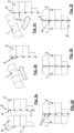
- Possible designs of a further connecting means 6 are shown in the Fig. 1c shown - one embodiment in the two upper figures and another embodiment in the two lower figures.
- the two profiles 1 and 2 are shown before joining (left) and after joining (right).
- the positive connection used here can use a flange pointing away from the connecting surface 3 (above) or be designed without such a flange (below).
- Fig.2 is a schematic representation of the joining process of a motor vehicle component according to the invention, in three process steps (from left to right).
- adhesive is applied as a connecting means 4 in the form of an adhesive bead to a connecting surface 3 of at least one of the profiles 1, 2.
- the two connecting surfaces 3 or the profiles 1, 2 are pivoted towards each other on a pivot axis 10, whereby the adhesive can be distributed well between the two connecting surfaces 3.
- Fig. 3 a to f show process steps in the manufacture of a motor vehicle component according to the invention according to Fig. 1a , namely a two-part sill.
- Fig. 3a only the second profile 2 is shown twice, namely on the left without applied adhesive beads and right with adhesive beads as connecting means 4, which were applied to the connecting surface 3 of the second profile 2.
- a first profile 1 is fed to the second profile 2.
- the first and the second profile 1, 2 are positively hooked into each other, whereby the remaining connecting surfaces 3 are still spaced apart from each other.
- the two profiles 1, 2 are then rotated around the pivot axis 10 ( Fig. 1b ) in the form-fitting connection at the end 5 of the connecting surfaces 3, for example the first profile 1 is pivoted towards the second profile 2.
- Fig. 3d It is shown how the adhesive beads are increasingly distributed over the connecting surfaces 3 as the two connecting surfaces 3 approach each other in sections, starting at the end 5 where the pivot axis is located (in Fig. 3c above). The distribution of the adhesive on the connecting surfaces 3 is thus particularly controlled.
- the connecting agent 4 the adhesive of all adhesive beads, is distributed over the connecting surfaces 3 in the areas where there is no recess 7.
- a connection can be made by one or more further connecting means 6 at the end of the connecting surfaces 3 that is opposite the end 5.
- This further connection can be made, for example, by clamping a flange between other components or by additional fastening elements or by an additional positive connection between the profiles 1 and 2.
- the further connecting means 6 can fix both profiles 1, 2, for example for the time it takes for the adhesive to harden and/or permanently.
- Fig.4 shows a three-dimensional representation of such a two-part sill according to the invention according to Fig. 1a , whereby the two profiles 1 and 2 are not yet joined together. Defined adhesive surfaces are created on the remaining connecting surfaces 3 between the horizontally extending recesses 7 in the longitudinal direction.
- connection technology can be saved on one side.
- a defined movement of the components relative to one another can be realized during the joining process.
- the adhesive surfaces can be brought together over an ever smaller angle until they are parallel ( Fig. 3a-f ). This results in a well-defined, reproducible adhesive distribution.
Landscapes
- Engineering & Computer Science (AREA)
- Mechanical Engineering (AREA)
- Chemical & Material Sciences (AREA)
- Combustion & Propulsion (AREA)
- Transportation (AREA)
- General Engineering & Computer Science (AREA)
- Body Structure For Vehicles (AREA)
- Standing Axle, Rod, Or Tube Structures Coupled By Welding, Adhesion, Or Deposition (AREA)
Abstract
Ein Kraftfahrzeugbauteil, insbesondere Schweller, umfassend ein erstes Profil (1) und ein zweites Profil (2), wobei das erste Profil (1) und das zweite Profil (2) jeweils eine Verbindungsfläche (3) aufweisen, wobei das erste und das zweite Profil (1, 2) an deren Verbindungsflächen (3) mit Hilfe zumindest eines Verbindungsmittels (4) aneinander gefügt sind, wobei das erste Profil und das zweite Profil an einem Ende (5) der Verbindungsfläche (3) formschlüssig miteinander verbunden sind und ein Verfahren zur Herstellung eines solchen Kraftfahrzeugbauteils.
Description
- Die vorliegende Erfindung betrifft ein Kraftfahrzeugbauteil, insbesondere einen Schweller, umfassend ein erstes Profil und ein zweites Profil. Die Erfindung betrifft auch ein Verfahren zur Herstellung eines solchen Kraftfahrzeugbauteils.
- Es ist bekannt, dass manche Kraftfahrzeugbauteile aus mehreren, oft langen Profilen zusammengebaut werden, insbesondere können beispielsweise die Schweller eines Kraftfahrzeugs aus zwei oder mehr sich in Fahrzeuglängsrichtung erstreckenden Hohlprofilen gebildet sein. Derartige Profile können großflächig an Verbindungsflächen, wie beispielsweise Klebeflächen, miteinander verbunden und gefügt sein. Ein solches Kraftfahrzeugbauteil kann insbesondere ein mehrteiliger Schweller sein. Die Profile können mittels kontinuierlichen Herstellungsprozessen, wie zum Beispiel Strangpressen gefertigt sein. Die Profile können an den Längsflächen als Verbindungsflächen miteinander verbunden sein, beispielsweise durch großflächiges Kleben, Nieten oder Schweißen. Das Kraftfahrzeugbauteil kann somit ein aus mehreren Strangpressprofilen zusammengesetzter Schweller sein.
- Um derartige Profile miteinander zu verbinden, wird eine hohe Anzahl von Verbindungspunkten, wie Stanzniete, Widerstandspunktschweißpunkte, und/oder große Befestigungsflächen beispielsweise für eine Verklebung benötigt.
- Es ist eine Aufgabe der Erfindung, ein Kraftfahrzeugbauteil, insbesondere einen Schweller, anzugeben, der aus mindestens zwei Profilen besteht, die auf einfachere und kostengünstigere Weise, zuverlässig aneinander gefügt sind. Eine weitere Aufgabe der Erfindung ist es, ein einfaches und kostengünstiges Verfahren zur Herstellung eines solchen Kraftfahrzeugbauteils anzugeben.
- Die Lösung der Aufgabe erfolgt durch ein Kraftfahrzeugbauteil, insbesondere Schweller, umfassend ein erstes Profil und ein zweites Profil, wobei das erste Profil und das zweite Profil jeweils eine Verbindungsfläche aufweisen, wobei das erste und das zweite Profil an deren Verbindungsflächen mit Hilfe zumindest eines Verbindungsmittels aneinander gefügt sind, wobei das erste Profil und das zweite Profil an einem Ende der Verbindungsfläche formschlüssig miteinander verbunden sind.
- Erfindungsgemäß sind ein erstes Profil und ein zweites Profil an einer Verbindungsfläche aneinander gefügt. Dazu wird zumindest ein Verbindungsmittel verwendet, das vorzugsweise ein separates Element ist, zusätzlich zu den beiden Profilen, beispielsweise ein Klebstoff, um die beiden Verbindungsflächen miteinander zu verkleben. Das Verbindungsmittel kann auch durch die beiden Profile selbst ausgebildet sein, insbesondere als formschlüssige Verbindung der beiden Profile aneinander. Zusätzlich zu diesem Verbindungsmittel für die Verbindungsflächen, erfolgt das Fügen der beiden Profile über ein bauteilintegriertes Verbindungssystem, dass die Enden der Verbindungsflächen der beiden Profile aneinander fügt, nämlich über eine formschlüssige Verbindung der Enden der Verbindungsflächen beiden Profile aneinander. Die formschlüssige Verbindung ist an einem Ende der Verbindungsfläche, also an einem Rand der Verbindungsfläche ausgebildet, und zwar bevorzugt genau an einem Ende bzw. an einem Rand der Verbindungsfläche, also einseitig, und in einer anderen Ausführungsform an zwei gegenüberliegenden Enden bzw. Rändern der Verbindungsfläche, also zweiseitig an den Enden der Verbindungsfläche.
- Dadurch, dass das erste und das zweite Profil an einem Ende der Verbindungsfläche formschlüssig miteinander verbunden sind, kann die sonstige Verbindung der Verbindungsflächen reduziert oder vereinfacht werden und Verbindungsmittel eingespart werden, oder die Qualität der Verbindung bessert werden.
- Weiterbildungen der Erfindung sind in den abhängigen Ansprüchen, der Beschreibung sowie den beigefügten Zeichnungen angegeben.
- Vorzugsweise erstreckt sich das Ende der Verbindungsfläche, an welchem die beiden Profile formschlüssig miteinander verbunden sind, entlang einer Längsrichtung, also x-Richtung, der beiden Profile. Die beiden Profile sind somit über deren Länge, bevorzugt über im Wesentlichen deren gesamte Länge, formschlüssig miteinander verbunden. Diese Längsrichtung der Profile liegt bevorzugt in der vorgesehenen Einbaulage in einem Kraftfahrzeug ebenfalls in x-Richtung des Fahrzeugs, als in Fahrzeuglängsrichtung. Die Verbindungsfläche und die formschlüssige Verbindung kann sich über mindestens 40%, bevorzugt mindestens 60 %, besonders bevorzugt mindestens 80% der Länge des Profils und/oder in Einbaulage in einem Fahrzeug der Länge des Fahrzeugs erstrecken.
- Bevorzugt sind das erste Profil und das zweite Profil an dem Ende der Verbindungsfläche durch eine dreh- oder schwenkbare Verbindung formschlüssig miteinander verbunden. Die beiden Profile greifen somit in einer dreh- oder schwenkbaren Weise ineinander ein. Die formschlüssige Verbindung bildet eine Dreh- oder Schwenkachse aus. Hierdurch kann beispielsweise Klebstoff als Verbindungsmittel an der Verbindungsfläche gezielter aufgetragen werden und die Qualität der Verklebung verbessert werden.
- Bevorzugt sind das erste Profil und das zweite Profil an dem Ende der Verbindungsfläche so formschlüssig miteinander verbunden, dass die beiden Profile zumindest im Bereich des Endes der Verbindungsfläche zumindest in den beiden Querrichtungen zur Längsrichtung der beiden Profile, also in y- und z-Richtung, festgelegt sind.
- Vorzugsweise sind das erste Profil und das zweite Profil an demjenigen Ende, dass dem Ende der Verbindungsfläche an welchem die beiden Profile formschlüssig miteinander verbunden sind gegenüberliegt, durch die Verbindungsmittel oder durch weitere Verbindungsmittel aneinander befestigt. An diesem gegenüberliegenden Ende der Verbindungsfläche kann somit das Verbindungsmittel verwendet werden, dass dem Fügen der Verbindungsflächen dient, oder es kann ein anderes Verbindungsmittel zusätzlich zu einem Verbindungsmittel an der Verbindungsfläche verwendet werden, beispielsweise Schrauben, Nieten oder Klemmen zusätzlich zu einem Klebstoff. Das weitere Verbindungsmittel kann auch durch eine formschlüssige Verbindung der beiden Profile aneinander, insbesondere durch eine Steckverbindung, gebildet sein.
- Bevorzugt ist das Verbindungsmittel Klebstoff und/oder Nieten, Schrauben oder eine Verschweißung.
- Bevorzugt weist die Verbindungsfläche Vertiefungen auf, beispielsweise Nuten, so dass die Verbindungsfläche durch die Vertiefungen in mehrere kleinere Verbindungsflächen aufgeteilt ist. Die Vertiefungen können sich bevorzugt in Längsrichtung der beiden Profile erstrecken.
- Ein erfindungsgemäßes Verfahren zur Herstellung eines solchen Kraftfahrzeugbauteils kann vorsehen, dass das erste Profil und das zweite Profil separat voneinander bereitgestellt werden, dass danach das erste Profil und das zweite Profil an einem Ende der Verbindungsfläche formschlüssig miteinander verbunden werden und dass danach das erste und das zweite Profil an deren Verbindungsflächen durch Verbindungsmittel aneinander befestigt werden und/oder zumindest an demjenigen Ende, dass dem Ende der Verbindungsfläche an welchem die beiden Profile formschlüssig miteinander verbunden sind gegenüberliegt, durch die Verbindungsmittel oder durch weitere Verbindungsmittel aneinander befestigt werden.
- Bevorzugt werden das erste Profil und das zweite Profil an dem Ende der Verbindungsfläche formschlüssig miteinander verbunden, insbesondere ein Profil in das andere Profil eingehängt oder eingeschoben, wobei die beiden Verbindungsflächen zunächst nicht parallel zueinander ausgerichtet sind, und dass danach das erste und das zweite Profil zueinander geschwenkt werden, so dass deren Verbindungsflächen parallel zueinander ausgerichtet werden, und dass dabei, oder danach, die beiden Verbindungsflächen durch Verbindungsmittel aneinander befestigt werden, zumindest an demjenigen Ende, dass dem Ende der Verbindungsfläche an welchem die beiden Profile formschlüssig miteinander verbunden sind, gegenüberliegt.
- Die Erfindung wird im Folgenden beispielhaft unter Bezugnahme auf die Zeichnungen beschrieben.
- Fig. 1a
- ist eine Schnittansicht eines erfindungsgemäßen Kraftfahrzeugbauteils mit daran befestigter Antriebsbatterie.
- Fig. 1b
- ist eine Detaildarstellung des in
Fig. 1a eingezeichneten Ausschnitts (oben) des Kraftfahrzeugbauteils gemäßFig. 1a . - Fig. 1c
- ist eine Detaildarstellung des in
Fig. 1a eingezeichneten Ausschnitts im Bereich des weiteren Verbindungsmittels (unten) des Kraftfahrzeugbauteils gemäßFig. 1a . - Fig. 2
- ist eine schematische Darstellung des Fügeprozesses eines erfindungsgemäßen Kraftfahrzeugbauteils.
- Fig. 3 a-f
- zeigen Verfahrensschritte bei der Herstellung eines erfindungsgemäßen Kraftfahrzeugbauteils gemäß
Fig. 1a . - Fig. 4
- ist eine dreidimensionale Darstellung eines erfindungsgemäßen Kraftfahrzeugbauteils gemäß
Fig. 1a . - In
Fig. 1a ist ein erfindungsgemäßes Kraftfahrzeugbauteil dargestellt, mit einer daran über ein Befestigungsmittel 8 befestigten Antriebsbatterie 9. - Das Kraftfahrzeugbauteil ist ein zweiteiliger Schweller, umfassend ein erstes Profil 1 und ein zweites Profil 2, wobei das erste Profil 1 und das zweite Profil 2 jeweils eine Verbindungsfläche 3 aufweisen, wobei das erste und das zweite Profil 1, 2 an deren Verbindungsflächen 3 mit Hilfe zumindest eines Verbindungsmittels 4, nämlich mit Klebstoff, aneinander gefügt sind. Die Verbindungsflächen 3 eines oder beider Profile 1, 2 können Vertiefungen 7 aufweisen, so dass die Verbindungsfläche 3 durch die Vertiefungen 7 in mehrere kleinere Verbindungsflächen 3 aufgeteilt sein kann.
- Das erste Profil 1 und das zweite Profil 2 sind erfindungsgemäß an einem Ende 5 der Verbindungsfläche 3 formschlüssig miteinander verbunden. Dieses Ende 5 der Verbindungsfläche 3 ist in
Fig. 1b im Detail dargestellt. Die beiden Profile weisen an den Enden 5 der Verbindungsflächen 3 jeweils kreisbogenförmige Fortsätze auf, die ineinander liegen. Hierdurch wird eine formschlüssige Verbindung zwischen den beiden Profilen 1, 2 erreicht, die eine Schwenkbewegung um eine Schwenkachse 10 ermöglicht. - Das Ende 5 der Verbindungsfläche 3, an welchem die beiden Profile 1, 2 formschlüssig miteinander verbunden sind, erstreckt sich entlang einer Längsrichtung, also x-Richtung, der beiden Profile 1, 2. Die Schwenkachse 10 ist in dieser Längsrichtung der Profile 1, 2 ausgerichtet.
- Das erste Profil 1 und das zweite Profil 2 sind an dem Ende der Verbindungsfläche 3 so formschlüssig miteinander verbunden, dass die beiden Profile 1, 2 im Bereich des Endes 5 der Verbindungsfläche 3 zumindest in den beiden Querrichtungen zur Längsrichtung der beiden Profile 1, 2, also in y- und z-Richtung, festgelegt sind - siehe
Fig. 1b . - Das erste Profil 1 und das zweite Profil 2 können an demjenigen Ende, dass dem Ende 5 der Verbindungsfläche 3 an welchem die beiden Profile 1, 2 formschlüssig miteinander verbunden sind gegenüberliegt, durch die Verbindungsmittel 4 oder durch weitere Verbindungsmittel 6 aneinander befestigt sein. Mögliche Ausführungen eines weiteren Verbindungsmittels 6 sind in den
Fig. 1c dargestellt - eine Ausführungsform in den beiden oberen Abbildungen und eine andere Ausführungsform in den beiden unteren Abbildungen. Dabei sind die beiden Profile 1 und 2 jeweils vor dem Fügen (links) und nach dem Fügen (rechts) dargestellt. Die hier verwendete formschlüssige Verbindung kann einen von der Verbindungsfläche 3 wegweisenden Flasch verwenden (oben) oder ohne einen solchen Flansch ausgebildet sein (unten). -
Fig. 2 ist eine schematische Darstellung des Fügeprozesses eines erfindungsgemäßen Kraftfahrzeugbauteils, in drei Verfahrensschritten (von links nach rechts). Zunächst wird Klebstoff als Verbindungsmittel 4 in Form einer Klebstoffraupe auf eine Verbindungsfläche 3 zumindest eines der Profile 1, 2 aufgebracht. Die beiden Verbindungsflächen 3 bzw. die Profile 1, 2 werden an einer Schwenkachse 10 zueinander geschwenkt, wobei sich der Klebstoff gut zwischen den beiden Verbindungsflächen 3 verteilen kann. - Die
Fig. 3 a bis f zeigen Verfahrensschritte bei der Herstellung eines erfindungsgemäßen Kraftfahrzeugbauteils gemäßFig. 1a , nämlich eines zweiteiligen Schwellers. InFig. 3a ist lediglich das zweite Profil 2 zweimal dargestellt, nämlich links noch ohne aufgebrachte Klebstoffraupen und rechts mit Klebstoffraupen als Verbindungsmittel 4, die auf die Verbindungsfläche 3 des zweiten Profils 2 aufgebracht wurden. - In
Fig. 3b wird ein erstes Profil 1 dem zweiten Profil 2 zugeführt. Im Bereich des Endes 5 der Verbindungsflächen 3 werden das erste und das zweite Profil 1, 2 fomrschlüssig ineinander eingehängt, wobei die restlichen Verbindungsflächen 3 noch voneinander entfernt sind. - Wie in
Fig. 3c dargestellt, werden die beiden Profile 1, 2 danach um die Schwenkachse 10 (Fig. 1b ) bei der formschlüssigen Verbindung am Ende 5 der Verbindungsflächen 3 geschwenkt, beispielsweise das erste Profil 1 zum zweiten Profil 2 hin geschwenkt. - In
Fig. 3d ist dargestellt, wie sich die Kleberaupen durch die abschnittsweise zunehmende Annäherung der beiden Verbindungsflächen 3 immer mehr auf die Verbindungsflächen 3 verteilen, beginnend an dem Ende 5 an dem die Schwenkachse liegt (inFig. 3c oben). Die Verteilung des Klebstoffs auf die Verbindungsflächen 3 erfolgt dadurch besonders kontrolliert. InFig. 3e ist schließlich das Verbindungsmittel 4, der Klebstoff aller Kleberaupen, auf die Verbindungsflächen 3, in den Bereichen in denen keine Vertiefung 7 liegt, verteilt. - In
Fig. 3f ist schließlich noch dargestellt, dass zusätzlich zur Verbindung mit dem Verbindungsmittel 4 an den Verbindungsflächen 3, eine Verbindung durch ein oder mehrere weitere Verbindungsmittel 6 an dem Ende der Verbindungsflächen 3 erfolgen kann, dass dem Ende 5 gegenüberliegt. Diese weitere Verbindung kann beispielsweise durch Klemmen eines Flansches zwischen anderen Bauteilen oder durch zusätzliche Befestigungselemente oder durch eine zusätzliche formschlüssige Verbindung zwischen den Profilen 1 und 2 erfolgen. Das weitere Verbindungsmittel 6 kann die beiden Profile 1, 2 beispielsweise für die Zeit des Aushärtens des Klebstoffs und/oder dauerhaft fixieren. -
Fig. 4 zeigt eine dreidimensionale Darstellung eines derartigen erfindungsgemäßen zweiteiligen Schwellers gemäßFig. 1a , wobei die beiden Profile 1 und 2 noch nicht aneinander gefügt sind. Zwischen den horizontal in Längsrichtung verlaufenden Vertiefungen 7 werden definierte Klebeflächen an den verbleibenden Verbindungsflächen 3 geschaffen. - Durch eine bauteilintegrierte formschlüssige Verbindung zwischen den Bauteilen im Bereich des Endes 5 der Verbindungsflächen 3 kann beispielsweise Verbindungstechnik auf einer Seite eingespart werden. Zusätzlich kann während des Fügeprozesses eine definierte Bewegung der Bauteile zueinander realisiert werden. Zum Beispiel können durch eine geführte Drehbewegung bzw. Schwenkbewegung beim Fügen, die Klebeflächen über einen immer kleiner werdenden Winkel bis zur Parallelität zusammengeführt werden (
Fig. 3a-f ). Man erhält so eine gut definierte, reproduzierbare Klebstoffverteilung. -
- 1
- erstes Profil
- 2
- zweites Profil
- 3
- Verbindungsfläche
- 4
- Verbindungsmittel
- 5
- Ende der Verbindungsfläche
- 6
- weiteres Verbindungsmittel
- 7
- Vertiefung
- 8
- Befestigungsmittel
- 9
- Antriebsbatterie
- 10
- Schwenkachse
Claims (9)
- Kraftfahrzeugbauteil, insbesondere Schweller, umfassend ein erstes Profil (1) und ein zweites Profil (2), wobei das erste Profil (1) und das zweite Profil (2) jeweils eine Verbindungsfläche (3) aufweisen, wobei das erste und das zweite Profil (1, 2) an deren Verbindungsflächen (3) mit Hilfe zumindest eines Verbindungsmittels (4) aneinander gefügt sind,
dadurch gekennzeichnet, dass das erste Profil und das zweite Profil an einem Ende (5) der Verbindungsfläche (3) formschlüssig miteinander verbunden sind. - Kraftfahrzeugbauteil nach Anspruch 1,
dadurch gekennzeichnet, dass sich das Ende (5) der Verbindungsfläche (3), an welchem die beiden Profile (1, 2) formschlüssig miteinander verbunden sind, entlang einer Längsrichtung, also x-Richtung, der beiden Profile (1, 2) erstreckt. - Kraftfahrzeugbauteil nach zumindest einem der vorhergehenden Ansprüche,
dadurch gekennzeichnet, dass das erste Profil (1) und das zweite Profil (2) an dem Ende (5) der Verbindungsfläche (3) durch eine dreh- oder schwenkbare Verbindung formschlüssig miteinander verbunden sind. - Kraftfahrzeugbauteil nach zumindest einem der vorhergehenden Ansprüche,
dadurch gekennzeichnet, dass das erste Profil (1) und das zweite Profil (2) an dem Ende der Verbindungsfläche (3) so formschlüssig miteinander verbunden sind, dass die beiden Profile (1, 2) zumindest im Bereich des Endes (5) der Verbindungsfläche (3) zumindest in den beiden Querrichtungen zur Längsrichtung der beiden Profile (1, 2), also in y- und z-Richtung, festgelegt sind. - Kraftfahrzeugbauteil nach zumindest einem der vorhergehenden Ansprüche,
dadurch gekennzeichnet, dass das erste Profil (1) und das zweite Profil (2) an demjenigen Ende, dass dem Ende (5) der Verbindungsfläche (3) an welchem die beiden Profile (1, 2) formschlüssig miteinander verbunden sind gegenüberliegt, durch die Verbindungsmittel (4) oder durch weitere Verbindungsmittel (6) aneinander befestigt sind. - Kraftfahrzeugbauteil nach zumindest einem der vorhergehenden Ansprüche,
dadurch gekennzeichnet, dass das Verbindungsmittel (4) Klebstoff ist und/oder Nieten, Schrauben oder eine Verschweißung. - Kraftfahrzeugbauteil nach zumindest einem der vorhergehenden Ansprüche,
dadurch gekennzeichnet, dass die Verbindungsfläche (3) Vertiefungen (7) aufweist, so dass die Verbindungsfläche (3) durch die Vertiefungen (7) in mehrere kleinere Verbindungsflächen (3) aufgeteilt ist. - Verfahren zur Herstellung eines Kraftfahrzeugbauteils nach zumindest einem der vorhergehenden Ansprüche,
dadurch gekennzeichnet , dass das erste Profil (1) und das zweite Profil (2) separat voneinander bereitgestellt werden, dass danach das erste Profil (1) und das zweite Profil (2) an einem Ende (5) der Verbindungsfläche (3) formschlüssig miteinander verbunden werden und dass danach das erste und das zweite Profil (1, 2) an deren Verbindungsflächen (3) durch Verbindungsmittel (4) aneinander befestigt werden und/oder zumindest an demjenigen Ende, dass dem Ende (5) der Verbindungsfläche (3) an welchem die beiden Profile (1, 2) formschlüssig miteinander verbunden sind gegenüberliegt, durch die Verbindungsmittel (4) oder durch weitere Verbindungsmittel (6) aneinander befestigt werden. - Verfahren nach Anspruch 8,
dadurch gekennzeichnet , dass das erste Profil (1) und das zweite Profil (2) an dem Ende (5) der Verbindungsfläche (3) formschlüssig miteinander verbunden werden, insbesondere ein Profil (1, 2) in das andere Profil (1, 2) eingehängt oder eingeschoben wird, wobei die beiden Verbindungsflächen (3) nicht parallel zueinander ausgerichtet sind, und dass danach das erste und das zweite Profil (1, 2) zueinander geschwenkt werden, so dass deren Verbindungsflächen (3) parallel zueinander ausgerichtet werden, und dass dabei oder danach die beiden Verbindungsflächen (3) durch Verbindungsmittel (4) aneinander befestigt werden, zumindest an demjenigen Ende, dass dem Ende (5) der Verbindungsfläche (3), an welchem die beiden Profile (1, 2) formschlüssig miteinander verbunden sind, gegenüberliegt.
Applications Claiming Priority (1)
| Application Number | Priority Date | Filing Date | Title |
|---|---|---|---|
| DE102022214326.4A DE102022214326A1 (de) | 2022-12-22 | 2022-12-22 | Kraftfahrzeugbauteil umfassend zwei Profile |
Publications (1)
| Publication Number | Publication Date |
|---|---|
| EP4389568A1 true EP4389568A1 (de) | 2024-06-26 |
Family
ID=88510794
Family Applications (1)
| Application Number | Title | Priority Date | Filing Date |
|---|---|---|---|
| EP23205587.1A Pending EP4389568A1 (de) | 2022-12-22 | 2023-10-24 | Kraftfahrzeugbauteil umfassend zwei profile |
Country Status (4)
| Country | Link |
|---|---|
| US (1) | US20240208589A1 (de) |
| EP (1) | EP4389568A1 (de) |
| CN (1) | CN118238902A (de) |
| DE (1) | DE102022214326A1 (de) |
Citations (4)
| Publication number | Priority date | Publication date | Assignee | Title |
|---|---|---|---|---|
| DE19633911A1 (de) * | 1996-08-22 | 1998-02-26 | Bayerische Motoren Werke Ag | Verfahren zur Reparatur einer Fahrzeugkarosserie |
| DE102008057882A1 (de) * | 2008-11-18 | 2010-05-20 | Audi Ag | Karosserieteil für ein Kraftfahrzeug |
| DE102018127368A1 (de) * | 2018-11-02 | 2020-05-07 | Benteler Automobiltechnik Gmbh | Schweller und Fahrzeugrahmen einer Fahrzeugkarosserie und Verfahren zur Herstellung eines Schwellers |
| DE102021004896A1 (de) * | 2021-09-28 | 2022-09-08 | Mercedes-Benz Group AG | Seitenschweller für eine Kraftwagenkarosserie sowie Baukastensystem |
Family Cites Families (2)
| Publication number | Priority date | Publication date | Assignee | Title |
|---|---|---|---|---|
| US12060111B2 (en) * | 2019-09-25 | 2024-08-13 | Posco | Side sill for vehicle |
| KR20240047698A (ko) * | 2022-10-05 | 2024-04-12 | 현대자동차주식회사 | 차량용 사이드실 보강멤버 및 이를 포함하는 차량용 사이드실 어셈블리 |
-
2022
- 2022-12-22 DE DE102022214326.4A patent/DE102022214326A1/de active Pending
-
2023
- 2023-10-24 EP EP23205587.1A patent/EP4389568A1/de active Pending
- 2023-12-05 US US18/530,149 patent/US20240208589A1/en active Pending
- 2023-12-21 CN CN202311773575.2A patent/CN118238902A/zh active Pending
Patent Citations (4)
| Publication number | Priority date | Publication date | Assignee | Title |
|---|---|---|---|---|
| DE19633911A1 (de) * | 1996-08-22 | 1998-02-26 | Bayerische Motoren Werke Ag | Verfahren zur Reparatur einer Fahrzeugkarosserie |
| DE102008057882A1 (de) * | 2008-11-18 | 2010-05-20 | Audi Ag | Karosserieteil für ein Kraftfahrzeug |
| DE102018127368A1 (de) * | 2018-11-02 | 2020-05-07 | Benteler Automobiltechnik Gmbh | Schweller und Fahrzeugrahmen einer Fahrzeugkarosserie und Verfahren zur Herstellung eines Schwellers |
| DE102021004896A1 (de) * | 2021-09-28 | 2022-09-08 | Mercedes-Benz Group AG | Seitenschweller für eine Kraftwagenkarosserie sowie Baukastensystem |
Also Published As
| Publication number | Publication date |
|---|---|
| DE102022214326A1 (de) | 2024-06-27 |
| CN118238902A (zh) | 2024-06-25 |
| US20240208589A1 (en) | 2024-06-27 |
Similar Documents
| Publication | Publication Date | Title |
|---|---|---|
| DE60015815T2 (de) | Drehendes Reibungsschweißverfahren zur Herstellung eines Bauteils und provisorisches Schweißen von Teilen des Bauteils | |
| EP1511668B1 (de) | Dreidimensionale knotenstruktur | |
| DE3811427C2 (de) | ||
| DE60013027T2 (de) | Bauteil und Verfahren zu seiner Herstellung | |
| DE69413458T2 (de) | Aufbau und Verfahren zum Zusammenfügen von Strangpressprofilen | |
| EP3357617A1 (de) | Profilbearbeitungsmaschine und profilbearbeitungsstrecke | |
| DE60102997T2 (de) | Reibrührschweißverfahren | |
| EP1492694B1 (de) | Y-knotenstruktur eines tragrahmens für fahrzeuge | |
| EP3693123B1 (de) | Gerippe-struktur mit einer vielzahl an profilelementen, und verfahren zum herstellen einer gerippe-struktur mit einer vielzahl an profilelementen | |
| DE102015001151A1 (de) | Verfahren zum Herstellen einer Schweißverbindung | |
| DE69313213T2 (de) | Klammer zur Verbindung von Modulplatten | |
| DE102022214326A1 (de) | Kraftfahrzeugbauteil umfassend zwei Profile | |
| DE19818597C1 (de) | Verbindungselement | |
| EP1798186B1 (de) | Aufzugskabine und Verfahren zum Montieren von Wandelementen einer Kabinenwand | |
| DE102020209298A1 (de) | Karosserie für ein Fahrzeug | |
| DE69517964T2 (de) | Rahmen | |
| EP3943703B1 (de) | Verfahren zum befestigen eines profils an einem stab, fensterrahmen und vorrichtung zur herstellung eines fensterrahmens oder fensterteilrahmens | |
| DE102013011421A1 (de) | Verfahren zum Fügen wenigstens eines Endbereichs eines Pultrusionsbauteils mit einem Bauteil | |
| DE102015117033A1 (de) | Blechanordnung sowie Verfahren zum Verschweißen von wenigstens zwei Blechen | |
| DE102021005006A1 (de) | Verfahren zum Verschweißen von Hohlprofilen, sowie Bauteil, hergestellt in einem solchen Verfahren | |
| DE69714052T2 (de) | Fahrzeugrahmen und herstellungsverfahren | |
| EP2085210A2 (de) | Verfahren zur Verbindung wenigstens eines ersten Kunststoff-Elements mit wenigstens einem zweiten Kunststoff-Element | |
| EP2030825B1 (de) | Verfahren zum Herstellen einer Klemmleiste | |
| DE102025106691B4 (de) | Schweißanordnung, Verfahren zum Verbinden von Kunststoffprodukten durch Schweißen und Verwendung des Verfahrens sowie des damit hergestellten Kunststoffprodukts | |
| DE102013223302A1 (de) | Verfahren zur Reparatur von Composite-verstärkten metallischen Strukturen in Hybridbauweise |
Legal Events
| Date | Code | Title | Description |
|---|---|---|---|
| PUAI | Public reference made under article 153(3) epc to a published international application that has entered the european phase |
Free format text: ORIGINAL CODE: 0009012 |
|
| STAA | Information on the status of an ep patent application or granted ep patent |
Free format text: STATUS: REQUEST FOR EXAMINATION WAS MADE |
|
| 17P | Request for examination filed |
Effective date: 20240508 |
|
| AK | Designated contracting states |
Kind code of ref document: A1 Designated state(s): AL AT BE BG CH CY CZ DE DK EE ES FI FR GB GR HR HU IE IS IT LI LT LU LV MC ME MK MT NL NO PL PT RO RS SE SI SK SM TR |