EP4387429A1 - Hocheffizientes energieabwärtsumwandlungssystem - Google Patents
Hocheffizientes energieabwärtsumwandlungssystem Download PDFInfo
- Publication number
- EP4387429A1 EP4387429A1 EP22856018.1A EP22856018A EP4387429A1 EP 4387429 A1 EP4387429 A1 EP 4387429A1 EP 22856018 A EP22856018 A EP 22856018A EP 4387429 A1 EP4387429 A1 EP 4387429A1
- Authority
- EP
- European Patent Office
- Prior art keywords
- moiety
- compound
- energy
- light
- light emitting
- Prior art date
- Legal status (The legal status is an assumption and is not a legal conclusion. Google has not performed a legal analysis and makes no representation as to the accuracy of the status listed.)
- Pending
Links
Images





Classifications
-
- H—ELECTRICITY
- H10—SEMICONDUCTOR DEVICES; ELECTRIC SOLID-STATE DEVICES NOT OTHERWISE PROVIDED FOR
- H10K—ORGANIC ELECTRIC SOLID-STATE DEVICES
- H10K65/00—Integrated devices, or assemblies of multiple devices, comprising at least one organic light-emitting element and at least one organic radiation-sensitive element, e.g. organic opto-couplers
-
- C—CHEMISTRY; METALLURGY
- C09—DYES; PAINTS; POLISHES; NATURAL RESINS; ADHESIVES; COMPOSITIONS NOT OTHERWISE PROVIDED FOR; APPLICATIONS OF MATERIALS NOT OTHERWISE PROVIDED FOR
- C09K—MATERIALS FOR MISCELLANEOUS APPLICATIONS, NOT PROVIDED FOR ELSEWHERE
- C09K11/00—Luminescent materials, e.g. electroluminescent or chemiluminescent
- C09K11/06—Luminescent materials, e.g. electroluminescent or chemiluminescent containing organic luminescent materials
-
- H—ELECTRICITY
- H10—SEMICONDUCTOR DEVICES; ELECTRIC SOLID-STATE DEVICES NOT OTHERWISE PROVIDED FOR
- H10K—ORGANIC ELECTRIC SOLID-STATE DEVICES
- H10K30/00—Organic devices sensitive to infrared radiation, light, electromagnetic radiation of shorter wavelength or corpuscular radiation
- H10K30/50—Photovoltaic [PV] devices
-
- H—ELECTRICITY
- H10—SEMICONDUCTOR DEVICES; ELECTRIC SOLID-STATE DEVICES NOT OTHERWISE PROVIDED FOR
- H10K—ORGANIC ELECTRIC SOLID-STATE DEVICES
- H10K59/00—Integrated devices, or assemblies of multiple devices, comprising at least one organic light-emitting element covered by group H10K50/00
- H10K59/30—Devices specially adapted for multicolour light emission
- H10K59/38—Devices specially adapted for multicolour light emission comprising colour filters or colour changing media [CCM]
-
- H—ELECTRICITY
- H10—SEMICONDUCTOR DEVICES; ELECTRIC SOLID-STATE DEVICES NOT OTHERWISE PROVIDED FOR
- H10K—ORGANIC ELECTRIC SOLID-STATE DEVICES
- H10K85/00—Organic materials used in the body or electrodes of devices covered by this subclass
- H10K85/30—Coordination compounds
- H10K85/341—Transition metal complexes, e.g. Ru(II)polypyridine complexes
- H10K85/342—Transition metal complexes, e.g. Ru(II)polypyridine complexes comprising iridium
-
- H—ELECTRICITY
- H10—SEMICONDUCTOR DEVICES; ELECTRIC SOLID-STATE DEVICES NOT OTHERWISE PROVIDED FOR
- H10K—ORGANIC ELECTRIC SOLID-STATE DEVICES
- H10K85/00—Organic materials used in the body or electrodes of devices covered by this subclass
- H10K85/30—Coordination compounds
- H10K85/341—Transition metal complexes, e.g. Ru(II)polypyridine complexes
- H10K85/346—Transition metal complexes, e.g. Ru(II)polypyridine complexes comprising platinum
-
- H—ELECTRICITY
- H10—SEMICONDUCTOR DEVICES; ELECTRIC SOLID-STATE DEVICES NOT OTHERWISE PROVIDED FOR
- H10K—ORGANIC ELECTRIC SOLID-STATE DEVICES
- H10K85/00—Organic materials used in the body or electrodes of devices covered by this subclass
- H10K85/60—Organic compounds having low molecular weight
- H10K85/615—Polycyclic condensed aromatic hydrocarbons, e.g. anthracene
-
- H—ELECTRICITY
- H10—SEMICONDUCTOR DEVICES; ELECTRIC SOLID-STATE DEVICES NOT OTHERWISE PROVIDED FOR
- H10K—ORGANIC ELECTRIC SOLID-STATE DEVICES
- H10K85/00—Organic materials used in the body or electrodes of devices covered by this subclass
- H10K85/60—Organic compounds having low molecular weight
- H10K85/649—Aromatic compounds comprising a hetero atom
- H10K85/654—Aromatic compounds comprising a hetero atom comprising only nitrogen as heteroatom
-
- H—ELECTRICITY
- H10—SEMICONDUCTOR DEVICES; ELECTRIC SOLID-STATE DEVICES NOT OTHERWISE PROVIDED FOR
- H10K—ORGANIC ELECTRIC SOLID-STATE DEVICES
- H10K85/00—Organic materials used in the body or electrodes of devices covered by this subclass
- H10K85/60—Organic compounds having low molecular weight
- H10K85/649—Aromatic compounds comprising a hetero atom
- H10K85/657—Polycyclic condensed heteroaromatic hydrocarbons
- H10K85/6572—Polycyclic condensed heteroaromatic hydrocarbons comprising only nitrogen in the heteroaromatic polycondensed ring system, e.g. phenanthroline or carbazole
-
- H—ELECTRICITY
- H10—SEMICONDUCTOR DEVICES; ELECTRIC SOLID-STATE DEVICES NOT OTHERWISE PROVIDED FOR
- H10K—ORGANIC ELECTRIC SOLID-STATE DEVICES
- H10K85/00—Organic materials used in the body or electrodes of devices covered by this subclass
- H10K85/60—Organic compounds having low molecular weight
- H10K85/658—Organoboranes
-
- C—CHEMISTRY; METALLURGY
- C09—DYES; PAINTS; POLISHES; NATURAL RESINS; ADHESIVES; COMPOSITIONS NOT OTHERWISE PROVIDED FOR; APPLICATIONS OF MATERIALS NOT OTHERWISE PROVIDED FOR
- C09K—MATERIALS FOR MISCELLANEOUS APPLICATIONS, NOT PROVIDED FOR ELSEWHERE
- C09K2211/00—Chemical nature of organic luminescent or tenebrescent compounds
- C09K2211/10—Non-macromolecular compounds
- C09K2211/1018—Heterocyclic compounds
- C09K2211/1025—Heterocyclic compounds characterised by ligands
- C09K2211/1029—Heterocyclic compounds characterised by ligands containing one nitrogen atom as the heteroatom
-
- C—CHEMISTRY; METALLURGY
- C09—DYES; PAINTS; POLISHES; NATURAL RESINS; ADHESIVES; COMPOSITIONS NOT OTHERWISE PROVIDED FOR; APPLICATIONS OF MATERIALS NOT OTHERWISE PROVIDED FOR
- C09K—MATERIALS FOR MISCELLANEOUS APPLICATIONS, NOT PROVIDED FOR ELSEWHERE
- C09K2211/00—Chemical nature of organic luminescent or tenebrescent compounds
- C09K2211/18—Metal complexes
- C09K2211/185—Metal complexes of the platinum group, i.e. Os, Ir, Pt, Ru, Rh or Pd
-
- H—ELECTRICITY
- H10—SEMICONDUCTOR DEVICES; ELECTRIC SOLID-STATE DEVICES NOT OTHERWISE PROVIDED FOR
- H10H—INORGANIC LIGHT-EMITTING SEMICONDUCTOR DEVICES HAVING POTENTIAL BARRIERS
- H10H20/00—Individual inorganic light-emitting semiconductor devices having potential barriers, e.g. light-emitting diodes [LED]
- H10H20/80—Constructional details
- H10H20/85—Packages
- H10H20/851—Wavelength conversion means
- H10H20/8511—Wavelength conversion means characterised by their material, e.g. binder
- H10H20/8512—Wavelength conversion materials
-
- H—ELECTRICITY
- H10—SEMICONDUCTOR DEVICES; ELECTRIC SOLID-STATE DEVICES NOT OTHERWISE PROVIDED FOR
- H10K—ORGANIC ELECTRIC SOLID-STATE DEVICES
- H10K2101/00—Properties of the organic materials covered by group H10K85/00
- H10K2101/30—Highest occupied molecular orbital [HOMO], lowest unoccupied molecular orbital [LUMO] or Fermi energy values
-
- H—ELECTRICITY
- H10—SEMICONDUCTOR DEVICES; ELECTRIC SOLID-STATE DEVICES NOT OTHERWISE PROVIDED FOR
- H10K—ORGANIC ELECTRIC SOLID-STATE DEVICES
- H10K2101/00—Properties of the organic materials covered by group H10K85/00
- H10K2101/40—Interrelation of parameters between multiple constituent active layers or sublayers, e.g. HOMO values in adjacent layers
-
- H—ELECTRICITY
- H10—SEMICONDUCTOR DEVICES; ELECTRIC SOLID-STATE DEVICES NOT OTHERWISE PROVIDED FOR
- H10K—ORGANIC ELECTRIC SOLID-STATE DEVICES
- H10K2101/00—Properties of the organic materials covered by group H10K85/00
- H10K2101/70—Down-conversion, e.g. by singlet fission
-
- H—ELECTRICITY
- H10—SEMICONDUCTOR DEVICES; ELECTRIC SOLID-STATE DEVICES NOT OTHERWISE PROVIDED FOR
- H10K—ORGANIC ELECTRIC SOLID-STATE DEVICES
- H10K85/00—Organic materials used in the body or electrodes of devices covered by this subclass
- H10K85/60—Organic compounds having low molecular weight
- H10K85/615—Polycyclic condensed aromatic hydrocarbons, e.g. anthracene
- H10K85/626—Polycyclic condensed aromatic hydrocarbons, e.g. anthracene containing more than one polycyclic condensed aromatic rings, e.g. bis-anthracene
-
- H—ELECTRICITY
- H10—SEMICONDUCTOR DEVICES; ELECTRIC SOLID-STATE DEVICES NOT OTHERWISE PROVIDED FOR
- H10K—ORGANIC ELECTRIC SOLID-STATE DEVICES
- H10K85/00—Organic materials used in the body or electrodes of devices covered by this subclass
- H10K85/60—Organic compounds having low molecular weight
- H10K85/631—Amine compounds having at least two aryl rest on at least one amine-nitrogen atom, e.g. triphenylamine
- H10K85/633—Amine compounds having at least two aryl rest on at least one amine-nitrogen atom, e.g. triphenylamine comprising polycyclic condensed aromatic hydrocarbons as substituents on the nitrogen atom
-
- H—ELECTRICITY
- H10—SEMICONDUCTOR DEVICES; ELECTRIC SOLID-STATE DEVICES NOT OTHERWISE PROVIDED FOR
- H10K—ORGANIC ELECTRIC SOLID-STATE DEVICES
- H10K85/00—Organic materials used in the body or electrodes of devices covered by this subclass
- H10K85/60—Organic compounds having low molecular weight
- H10K85/649—Aromatic compounds comprising a hetero atom
- H10K85/657—Polycyclic condensed heteroaromatic hydrocarbons
-
- Y—GENERAL TAGGING OF NEW TECHNOLOGICAL DEVELOPMENTS; GENERAL TAGGING OF CROSS-SECTIONAL TECHNOLOGIES SPANNING OVER SEVERAL SECTIONS OF THE IPC; TECHNICAL SUBJECTS COVERED BY FORMER USPC CROSS-REFERENCE ART COLLECTIONS [XRACs] AND DIGESTS
- Y02—TECHNOLOGIES OR APPLICATIONS FOR MITIGATION OR ADAPTATION AGAINST CLIMATE CHANGE
- Y02E—REDUCTION OF GREENHOUSE GAS [GHG] EMISSIONS, RELATED TO ENERGY GENERATION, TRANSMISSION OR DISTRIBUTION
- Y02E10/00—Energy generation through renewable energy sources
- Y02E10/50—Photovoltaic [PV] energy
- Y02E10/549—Organic PV cells
Definitions
- the present disclosure relates to a high efficiency energy down conversion system capable of high efficiency light conversion and its application.
- Methods for obtaining blue, green, red, and near infrared ray energy in organic or inorganic LEDs include a self-luminescence method and an energy down conversion method.
- the self-luminescence method obtains blue, green, red and nearz infrared energy by adjusting the band gap energy of an emission layer material, and the energy down conversion method allows a high energy light source to pass through a light conversion medium to obtain blue, green, red and near infrared energy.
- Small displays in which pixelation with a shadow metal mask is easily applied adopt the self-luminescence method, and ultra-small displays such as AR and VR, or large area displays in which it is difficult to apply a shadow metal mask adopt the energy down conversion method.
- An object of the present disclosure is to provide an energy down conversion system that increases energy conversion efficiency by minimizing energy loss while increasing energy absorption.
- One of more embodiments provide an energy down conversion system that receives energy from outside and converts it into low energy
- the energy down conversion system improves energy conversion efficiency by minimizing energy loss while increasing energy absorption.
- substitution means that a hydrogen atom bonded to a carbon atom in a compound is substituted with another substituent.
- the position where substitution occurs means the position where a hydrogen atom is substituted.
- the position is not limited as long as hydrogen at the position can be substituted with a substituent.
- the two or more substituents may be the same or different.
- a substituent in the case of being “substituted” may be one selected from the group consisting of, for example, deuterium, an alkyl group having 1 to 20 carbon atoms, an alkoxy group having 1 to 20 carbon atoms, a halogen, a cyano group, a carboxy group, a carbonyl group, an amine group, and an alkylamine group having 1 to 20 carbon atoms, a nitro group, an alkylsilyl group having 1 to 20 carbon atoms, an alkoxysilyl group having 1 to 20 carbon atoms, a cycloalkyl silyl group having 3 to 30 carbon atoms, an arylsilyl group having 6 to 30 carbon atoms, an aryl group having 6 to 30 carbon atoms, an arylamine group having 6 to 30 carbon atoms, a heteroaryl group having 5 to 30 carbon atoms, an aryl phosphine oxide group having 6 to 30 carbon atoms
- An energy down conversion system receives energy from the outside and converts it into low energy
- One embodiment provides an energy down conversion system in which the light emitting moiety and the light absorbing moiety in the multifunctional emitting compound are connected through a chemical bond.
- the light absorbing moiety functions to absorb energy applied from the outside, such as a light source.
- the connection portion by the chemical bond functions as a passage through which energy is transferred from the light absorbing moiety to the light emitting moiety.
- the light emitting moiety functions not only to absorb energy applied from the outside, but also to re-radiate the energy received from the light absorbing moiety.
- the energy down conversion system refers to a light converting (energy down conversion) system that absorbs high energy and emits light of low energy.
- the energy down conversion system can increase energy conversion efficiency by minimizing energy loss while increasing energy absorption.
- the light conversion method of the energy down conversion system can be widely used in areas such as displays, lightings, medical cares, and solar cells.
- the energy down conversion system improves light conversion efficiency by using the multifunctional emitting compound capable of increasing a rate constant value related to the energy transfer rate.
- Conventional energy down conversion systems use a light emitting compound alone or in a mixture with a polymer compound.
- a light emitting compound When a light emitting compound is used alone, it is common to mix it with a high molecular (or low molecular) compound with the very high bandgap energy and keep a distance between the light emitting compounds in order to avoid the problem of reduced quantum efficiency and long wavelength shift due to the concentration quenching phenomenon.
- the light conversion efficiency (Formula 3) of such an energy down conversion system is generally proportional to quantum efficiency of a light emitting compound and light absorbance of the system.
- Quantum Efficiency of a light emitting compound (Amount of Light emitted/Amount of Light absorbed)
- quantum efficiency of a light emitting compound is a material specific value
- light conversion efficiency varies depending on constitution and structure of a system. For example, if the concentration of a light emitting compound is increased, light absorbance is increased, but light conversion efficiency may be reduced due to the concentration quenching phenomenon. If the concentration of the light emitting compound is decreased and the thickness of the thin film is increased, light leakage may occur when a fine pixel structure is applied.
- the energy down conversion system to which the multifunctional emitting compound is applied can increase light absorbance while minimizing the concentration quenching phenomenon by increasing light conversion efficiency.
- the multifunctional emitting compound is formed by connecting the light absorbing moiety and the light emitting moiety through the chemical bond.
- the multifunctional emitting compound satisfies the condition of Formula 1 and Formula 2 when the wavelength of the light emitting moiety is greater than or equal to 350 nm and less than 2500 nm, and the light emitting moiety and the light absorbing moiety are chemically bonded so that the shortest distance between the moieties is formed within 10 ⁇ , and thus, the energy absorbed by the light absorbing moiety is transferred to the light emitting moiety.
- the HOMO energy of a compound or a moiety can be measured with methods such as Cyclic Voltammetry (CV), Ultraviolet Photoelectron Spectroscopy (UPS), AC2, etc. A value measured by UV absorption spectrum or Cyclic Voltammetry (CV) can be applied to obtain the LUMO energy.
- quantum efficiency of the materials as used herein can be obtained by measurements in dissolving the emitting materials in a solution, filming by co-evaporation with a host material, or dissolving the host material and the emitting material in a solution at the same time, followed by spin coating or casting to form a film.
- the light absorbing moiety and the light emitting moiety may be connected via a linking group, the light absorbing moiety and the light emitting moiety may be directly connected without a linking group, or the light absorbing moiety and the light emitting moiety may form a spiro connection that shares an atom capable of forming a spiro connection.
- the chemical bond between the light emitting moiety and the light absorbing moiety may include a single bond, a double bond, a triple bond or a coordinate bond.
- the linking group may include a substituted phenylene group; a substituted or unsubstituted arylene having 6 to 20 carbon atoms or heteroarylene having 5 to 20 carbon atoms, and the substituent when the phenylene group, the arylene and the heteroarylene are substituted is at least one selected from the group consisting of deuterium, an alkyl group having 1 to 20 carbon atoms, an alkoxy group having 1 to 20 carbon atoms, a halogen, a cyano group, a carboxy group, a carbonyl group, an amine group, an alkyl amine group having 1 to 20 carbon atoms, a nitro group, an alkylsilyl group having 1 to 20 carbon atoms, an alkoxysilyl group having 1 to 20 carbon atoms, cycloalkylsilyl group having 3 to 30 carbon atoms, arylsilyl group having 6 to
- the spiro connection may connect using carbon, silicon, or Ge as a spiro atom.
- the linking group is a conjugated structure such that the shortest distance between the light absorbing moiety and the light emitting moiety is within 10 ⁇ , and the bandgap energy of the conjugated structure is greater than that of the light absorbing moiety.
- the multifunctional emitting compound can be formed by chemically bonding the light absorbing compound and the light emitting compound.
- the light absorbing moiety originates from the light absorbing compound and the light emitting moiety originates from the light emitting compound.
- the light absorbing moiety and the light emitting moiety may be derived with a substituent or the like appropriately being modified.
- a chemical connection between the light absorbing moiety and the light emitting moiety should be formed so as not to significantly affect the electronic state of each of the light absorbing moiety and the light emitting moiety.
- "not to significantly affect” means that one moiety should not change the HOMO energy level, LUMO energy level, or HOMO-LUMO bandgap energy of the other moiety by more than 0.2 eV.
- an excited complex should not be formed between the light absorbing moiety and the light emitting moiety.
- the criterion for defining the electronic state of each moiety may be an independent compound state as a compound in which each moiety and a linking portion are separated by hydrogen substitution without including a connecting portion.
- the criterion for defining the electronic state of each moiety may be an independent compound state as a compound in which each moiety and a linking portion are separated by hydrogen substitution without including a connecting portion.
- the multifunctional emitting compound includes at least one light emitting moiety and at least one light absorbing moiety, and a combination of the light emitting moiety and the light absorbing moiety may be connected in a spiro connection.
- the multifunctional emitting compound may include a first light absorbing moiety, a second light absorbing moiety, and a light emitting moiety, and the detailed descriptions of the first light absorbing moiety and the second light absorbing moiety are the same as in the light absorbing moiety, and they may be the same or different from each other.
- the first light absorbing moiety may be connected to the light emitting moiety
- the second light absorbing moiety may be connected to the light emitting moiety or the first light absorbing moiety.
- the multifunctional emitting compound includes at least two light emitting moieties and at least two light absorbing moieties, and the light emitting moieties and the light absorbing moieties may be connected in a spiro connection by turns.
- At least one hydrogen atom may be substituted with deuterium.
- the energy down conversion system including the multifunctional emitting compound having a deuterium substituent may have improved material stability.
- Fig. 1 schematically shows the absorption-emission mechanism of a light emitting compound.
- the energy (I 1 ) applied from the outside is absorbed by the electrons in the HOMO of the light emitting compound in proportion to absorbance (A 1 ), transferred to the LUMO, and the energy (I 2 ) is re-emitted in proportion to quantum efficiency (Q 1 ), which is a conventional absorption-emission mechanism.
- FIG. 2 schematically shows an absorption-emission mechanism in a state in which a light absorbing compound and a light emitting compound are mixed.
- FIG. 2 is a case where the light absorbing compound exists independently of the light emitting compound.
- the light absorbing compound absorbs the energy (I 1 ) (proportional to absorbance (A 2 ) of the light absorbing compound) and re-emits the energy (I 3 ) (proportional to quantum efficiency (Q 2 ) of the light absorbing compound) by the same operating mechanism as in the light emitting compound of FIG.
- the light emitting compound absorbs the energy (I 3 ) emitted from the light absorbing compound in addition to the energy (I 1 ) applied from the outside, and then emits the energy (I 4 ).
- the emitted energy (I 4 ) is always greater than the emitted energy (I 2 ) when the light emitting compound exists alone.
- the amount of energy (I 4 ) is determined by energy transfer efficiency from the light absorbing compound to the light emitting compound.
- Energy transfer methods include a method by light in Equation 1 below (FRET, Förster Resonance Energy transfer) and a method by electrons in Equation 2 below (Dexter Electron Transfer).
- the energy transfer method is the method for light following Equation 1 or the method for electrons following Equation 2, it is the distance (r) between the energy donor and the energy acceptor that is meaningful.
- Equation 1 of energy transfer by light when the distance (r) approaches 0, quantum efficiency and the decay time of the energy donor (a light absorbing compound) become insignificant, and the theoretical energy transfer rate approaches infinity.
- Equation 2 of the energy transfer method by electron transfer when the distance (r) between the two materials approaches 0, the energy transfer rate is only affected by the degree of overlap (J) between the emission spectra and absorption spectra between the two materials.
- FIG. 3 schematically shows the absorption-emission mechanism of the multifunctional emitting compound in which the light absorbing moiety derived from a light absorbing compound and the light emitting moiety derived from a light emitting compound are combined.
- the multifunctional emitting compound includes the light absorbing moiety and the light emitting moiety in one molecule. Since the two moieties are connected while having little effect on the respective electronic energy state, the light absorption and emission characteristics do not change significantly compared to the case where each moiety exists as an independent compound before being connected. The energy absorbed by the light absorbing moiety is rapidly transferred to the light emitting moiety, and the light emitting moiety emits light through its electronic energy state, so that the emitted energy I 5 is greater than I 2 in FIG. 1 and I 4 in FIG. 2 .
- the light emitting moiety may be derived from a light emitting material capable of emitting light by absorbing energy applied from the outside (referred to herein as a light emitting compound).
- the light emitting compound (a light emitting material) may be commonly selected according to the desired light emitting wavelength range according to the purpose, and the light emitting moiety may be derived therefrom.
- the light emitting moiety may have a conjugated structure having a quantum efficiency of 10% or more in a visible light wavelength range of 400 nm to 650 nm.
- the light emitting moiety may have a conjugated structure having a quantum efficiency of 0.5% or more in the 650 nm to 2500 nm near infrared wavelength region.
- the light emitting compound (or the light emitting material) may be the following compounds, but are not limited thereto.
- Ar and R are, respectively, substituted or unsubstituted alkyl having 1 to 20 carbon atoms, substituted or unsubstituted aryl having 6 to 30 carbon atoms, substituted or unsubstituted heteroaryl having 5 to 30 carbon atoms, or substituted or unsubstituted aryl amine having 6 to 30 carbon atoms, and X is an element of nitrogen, oxygen, sulfur, carbon, silicon, Ge or P.
- the light emitting compound may be a boron compound in which nitrogen, oxygen, sulfur, carbon, silicon, Ge, P, etc. are substituted, a pyrene compound, a compound having a conjugated structure containing nitrogen, and the like, as such in the above structural formulae, but is not limited thereto.
- the materials known as light emitting materials may be used.
- the light emitting compounds has the conjugated structures such as anthracene, perylene, tetracene, chrysene, coumarine, pyromethene, etc.
- the light emitting compound and the light emitting moiety may have a conjugated structure including boron.
- the light emitting compound and the light emitting moiety may contain a metal.
- the light emitting mechanism of the light emitting moiety may include fluorescence emitting light from a singlet, phosphorescence emitting light from a triplet, and thermally activated delayed fluorescence emitting light when energy is transferred from a triplet to a singlet.
- the bandgap energy of the light absorbing moiety may have the band gap energy 0.5 eV to 4.7 eV and the light emitting moiety may have the band gap energy of 0.5 eV to 3.5 eV.
- the difference in the bandgap energies between the light absorbing moiety and the light emitting moiety may be 4eV or less.
- the light emitting moiety may be derived from a light emitting material capable of emitting light by absorbing energy applied from the outside (referred to herein as a light emitting compound).
- the light absorbing moiety may absorb energy applied from the outside and transfer it to the light emitting moiety, and may be designed to satisfy Equation 1 below and Equation 2 when the wavelength of the light emitting moiety is greater than or equal to 350 nm and less than 2500 nm.
- Equation 1 Equation 1 below and Equation 2 when the wavelength of the light emitting moiety is greater than or equal to 350 nm and less than 2500 nm.
- E(1) HOMO represents the HOMO energy of the light absorbing moiety
- E(1) LUMO represents the LUMO energy of the light absorbing moiety
- E(2) HOMO represents the HOMO energy of the light emitting moiety
- E(2) LUMO represents the LUMO energy of the light emitting moiety.
- I(A) represents the amount of light absorbed by the light emitting moiety
- I(E) represents the amount of light emitted by the light emitting moiety
- N(1) represents the amount of light absorbed by the light absorbing moiety
- N(2) represents the amount of light transferred to and emitted at the light emitting moiety.
- an appropriate light absorbing compound is connected to the light emitting compound that has been selected from a light emitting material, resulting in the multifunctional emitting compound, and thus the light absorbing moiety can be derived from the light absorbing compound.
- the light absorbing compound can be regarded as a precursor of the light absorbing moiety.
- the light absorbing compound inducing the light absorbing moiety may be selected from a compound that has a desired light absorption spectrum and satisfies Formula 1 and Formula 2 when the wavelength of the light emitting moiety is greater than or equal to 350 nm and less than 2500 nm.
- the light absorbing moiety may have a molar extinction coefficient of 1000 or more at a maximum absorption wavelength of 300 nm or more.
- the light absorbing compound inducing the light absorbing moiety may be selected from a compound that has a molar extinction coefficient of 500 or more and satisfies Formula 1 and Formula 2 when the wavelength of the light emitting moiety is greater than or equal to 350 nm and less than 2500 nm.
- the reason why the light conversion efficiency of the multifunctional emitting compound can be excellent can be understood by referring to FIG. 3 illustrating the absorption-emission mechanism of the multifunctional emitting compound as previously mentioned.
- the quantum efficiency of the light absorbing compound may not be considered when selecting the light absorbing compound in order to design the multifunctional emitting compound.
- the multifunctional emitting compound introduces a light absorbing moiety capable of only increasing absorption without affecting the emitting properties of the light emitting moiety. Since such energy is efficiently transferred to the light emitting moiety, excellent light conversion efficiency can be achieved.
- the energy down conversion system may implement a high efficiency light conversion system by being applied with the multifunctional emitting compound that absorbs a short wavelength light source and emits long wavelength light.
- the energy down conversion system may include a layer or a film including at least one kind of the multifunctional emitting compound.
- the layer including at least one kind of multifunctional emitting compound may, optionally, include a polymer compound for forming a matrix, further.
- the polymer compound for forming the matrix may include, for example, polyimide, poly acrylate, polyethylene terephthalate, and the like.
- the layer including at least one kind of multifunctional emitting compound may, optionally, include an inorganic compound, further.
- Examples of the inorganic compound include silicon oxide, aluminum oxide, titanium oxide, and molybdenium oxide.
- the multifunctional emitting compound may be applied to the energy down conversion system by a solution process.
- the layer may be prepared by a spin coating process, an inkjet process, a slow die coating process, or a silk screen printing process, which are examples of solution processes.
- the energy down conversion system can be applied not only to displays and lighting fields but also to solar cells and medical fields.
- materials capable of absorbing solar energy are positioned between an anode and a cathode. Once solar energy is absorbed, these materials become excited, and electrons move to the anode and holes move to the cathode, thereby generating electricity.
- Efficiency of electricity generation is proportional to light absorbance and proportional to the lifetime of the excited state of the material that has absorbed the light.
- the multifunctional emitting compound of the present disclosure absorbs high energy, transfers the energy to a light emitting moiety having high light emitting efficiency, and generates electrons and holes, thereby increasing electricity generation efficiency.
- the multifunctional emitting compound can obtain light with high efficiency even with small light source energy, it can be used for diagnosis by increasing sensitivity, converting it to have strong hydrophilic properties and by binding appropriate antigens or antibodies.
- by converting energy into near infrared rays using natural light or the visible light energy it can be used in the medical field where near infrared rays are applied.
- the energy down conversion system includes a light source, and the multifunctional emitting compound causes color conversion with respect to the light source. That is, the range of the maximum absorption wavelength can be adjusted while keeping the color of light emitted constant. This means that, while the conventional diagnosis has been made by the color of light emitted, the energy down conversion system can make a diagnosis by changing the wavelength of a light source.
- the light source may be an OLED light source or an inorganic LED light source.
- the multifunctional emitting compound may be applied as a fluorescent material for a diagnosis in biochemistry or medical fields.
- a case of applying the multifunctional emitting compound in which a red light emitting moiety is connected to a 450 nm wavelength light absorbing compound and a case of applying the multifunctional emitting compound in which a red light emitting moiety is connected to a 500 nm wavelength light absorbing compound. Both materials exhibit red light emission, but one material strongly appears red when irradiated with a 450 nm light source, and the other material strongly appears red when irradiated with a 500 nm light source.
- the multifunctional emitting compound when the multifunctional emitting compound is introduced into a specific region during cell division, it may be possible to check what function this region will express in the future by changing the measuring light source.
- the multifunctional emitting compound has an advantage of minimizing cell destruction by reducing the intensity of a light source because absorption is increased by the light absorbing moiety.
- One embodiment of the present disclosure provides an energy down conversion system wherein the energy down conversion system is an organic solar cell.
- the organic solar cell may include a first electrode, a second electrode, and a solar energy absorbing electricity generating layer interposed between the first electrode and the second electrode, and the solar energy absorption electricity generating layer may include the multifunctional emitting compound.
- the first electrode and the second electrode may be a cathode or an anode, respectively, or vice versa.
- the multifunctional emitting compound is used in a solar energy absorbing electricity generation layer between the first electrode and the second electrode of the organic solar cell, so that the light absorbing moiety increases the absorbance of high energy and short wavelength solar energy, and the light emitting moiety, to which it is transferred, converts it into a low energy state, thereby increasing electron generating efficiency.
- the organic solar cell may include a substrate and a film attached to the top of the substrate,
- the first electrode and the second electrode may be a cathode or an anode, respectively, or vice versa.
- the multifunctional emitting compound may be coated as a film on the substrate of the organic solar cell.
- the multifunctional emitting compound formed as a film on the substrate absorbs short wavelength solar energy with high energy and converts it to long wavelength energy with low energy, and the converted energy is absorbed in the solar energy absorbing electricity generating layer between the anode and the cathode of the organic solar cell, thereby increasing electron generating efficiency.
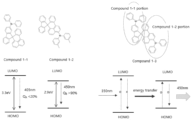
- Compound 1-1 was prepared as a light absorbing compound and Compound 1-2 was prepared as a light emitting compound.
- Fig. 4 schematically shows the absorption-emission mechanism of Compound 1-1, Compound 1-2 and Compound 1-3.
- the HOMO energy of the light absorbing moiety, E(1) HOMO ; the LUMO energy of the light absorbing moiety, E(1) LUMO ; the HOMO energy of the light emitting moiety, E(2) HOMO ; and the LUMO energy of the light emitting moiety, E(2) LUMO ; in Compound 1-3 were measured and the values of I E(1) HOMO - E(1) LUMO I , I E(2) HOMO - E(2) LUMO I in ⁇ Formula 1 > are shown in Table 1 below.
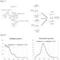
- Compound 2-1 was prepared as a light absorbing compound and compound 2-2 was prepared as a light emitting compound.
- Fig. 5 schematically shows the absorption-emission mechanism of Compound 2-1, Compound 2-2 and Compound 2-3.
- Compound 3-1 was prepared as a light absorbing compound and compound 3-2 was prepared as a light emitting compound.
- Fig. 6 schematically shows the absorption-emission mechanism of Compound 3-1, Compound 3-2 and Compound 3-3.
- the reactant was cooled to 0°C, and after adding 1.90 mL (20.0 mmol) of boron tribromide, followed by stirring at room temperature for 0.5 hour.
- the reactant was cooled to 0°C again, and 3.51 mL (20.0mmol) of N,N-diisopropylethylamine was added thereto, followed by stirring at 60-70°C for 2 hours.
- reaction solution was cooled to room temperature, and the organic layer was extracted with ethyl acetate. After drying the solvent of the extracted organic layer with MgSO4, it was filtered. After concentrating the filtrate under reduced pressure, it was purified using a silica gel column chromatography (DCM/Hexane) method.
- Compound 3-1 was prepared as a light absorbing compound and compound 3-2 was prepared as a light emitting compound.
- Fig. 7 schematically shows the absorption-emission mechanism of Compound 3-4 synthesized in Example.
- each material was dissolved in a toluene solution to have 2 micromolar concentration, and was measured using SHIMADZU RF5301PC, SHIMADZU UV 2550.
- Fig. 8 shows the absorption and the emission spectra measured for a mixture of Compound 1-1 and Compound 1-2.
- Compound 1-1 and Compound 1-2 were mixed at a ratio of 1:1 to have 2 micromolar concentration, respectively, and excited using 350 nm energy. As shown in FIG. 8 , it was confirmed that Compound 1-1 and Compound 1-2 emit light independently, and energy transfer does not occur well.
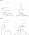
- FIG. 9 shows the absorption and the emission spectra measured for Compounds 1-1, 1-2 and 1-3.
- energy transfer between moieties in Compound 1-3 was confirmed by comparing the energy transfer phenomena of Compound 1-1, Compound 1-2 and Compound 1-3.
- FIG. 10 shows the absorption and the emission spectra measured for Compounds 2-1, 2-2 and 2-3.
- energy transfer between the moieties in Compound 2-3 was confirmed by comparing the energy transfer phenomena of Compound 2-1, Compound 2-2 and Compound 2-3.
- FIG. 10 shows the absorption and the emission spectra measured for Compounds 2-1, 2-2 and 2-3.
- FIG. 11 shows the absorption and the emission spectra measured for Compounds 3-1, 3-2 and 3-3.
- energy transfer between the moieties in Compound 3-3 was confirmed by comparing the energy transfer phenomena of Compound 3-1, Compound 3-2 and Compound 3-3.
- FIG. 11 shows the absorption and the emission spectra measured for Compounds 3-1, 3-2 and 3-3.
- Example 3 it was confirmed that energy transfer occurs efficiently when the distance between the energy donor (light absorbing compound) and the energy acceptor (light emitting compound) is very close (i.e., through chemical bonding.
- FIG. 12 shows the absorption and the emission spectra measured for Compounds 3-3 and 3-4. Through Compound 3-3 and Compound 3-4, the energy transfer phenomena were compared when one light absorbing moiety was connected and when two light absorbing moieties were connected.
- Fig. 13 is the emission spectrum measured for the films prepared in Comparative Example 2 and Example 5, respectively.
Landscapes
- Chemical & Material Sciences (AREA)
- Engineering & Computer Science (AREA)
- Materials Engineering (AREA)
- Physics & Mathematics (AREA)
- Spectroscopy & Molecular Physics (AREA)
- Crystallography & Structural Chemistry (AREA)
- Inorganic Chemistry (AREA)
- Electromagnetism (AREA)
- Organic Chemistry (AREA)
- Electroluminescent Light Sources (AREA)
- Optical Filters (AREA)
Applications Claiming Priority (3)
| Application Number | Priority Date | Filing Date | Title |
|---|---|---|---|
| KR20210105286 | 2021-08-10 | ||
| KR1020220082955A KR102494358B1 (ko) | 2021-08-10 | 2022-07-06 | 고효율의 에너지 다운 컨버젼 시스템 |
| PCT/KR2022/009856 WO2023018016A1 (ko) | 2021-08-10 | 2022-07-07 | 고효율의 에너지 다운 컨버젼 시스템 |
Publications (2)
| Publication Number | Publication Date |
|---|---|
| EP4387429A1 true EP4387429A1 (de) | 2024-06-19 |
| EP4387429A4 EP4387429A4 (de) | 2025-09-03 |
Family
ID=85200022
Family Applications (1)
| Application Number | Title | Priority Date | Filing Date |
|---|---|---|---|
| EP22856018.1A Pending EP4387429A4 (de) | 2021-08-10 | 2022-07-07 | Hocheffizientes energieabwärtsumwandlungssystem |
Country Status (4)
| Country | Link |
|---|---|
| US (1) | US20230422589A1 (de) |
| EP (1) | EP4387429A4 (de) |
| JP (1) | JP2024531145A (de) |
| WO (1) | WO2023018016A1 (de) |
Family Cites Families (11)
| Publication number | Priority date | Publication date | Assignee | Title |
|---|---|---|---|---|
| KR20150051830A (ko) * | 2013-11-05 | 2015-05-13 | 대주전자재료 주식회사 | 스파이로형 유기 재료 및 이를 이용한 유기 전기발광 소자 |
| US11201291B2 (en) * | 2015-07-30 | 2021-12-14 | Sichuan Knowledge Express Institute For Innovative Technologies Co., Ltd | Organic molecules having two non-conjugated bridges between a donor and an acceptor for effective thermally activated delayed fluorescence for use in optoelectronic devices |
| KR102112411B1 (ko) * | 2017-09-28 | 2020-05-18 | 주식회사 엘지화학 | 화합물 및 이를 포함하는 유기 발광 소자 |
| US12146087B2 (en) * | 2017-12-28 | 2024-11-19 | Idemitsu Kosan Co., Ltd. | Compound and organic electroluminescence device |
| JPWO2020075761A1 (ja) * | 2018-10-10 | 2021-09-24 | コニカミノルタ株式会社 | イミド誘導体、それを含有する発光性組成物、発光性薄膜及び発光性粒子 |
| EP3686206B1 (de) * | 2019-01-23 | 2021-10-27 | Cynora Gmbh | Organische moleküle für optoelektronische vorrichtungen |
| KR102827516B1 (ko) * | 2019-04-17 | 2025-07-01 | 엘지디스플레이 주식회사 | 유기전계 발광소자 |
| EP3763719A1 (de) * | 2019-07-11 | 2021-01-13 | Cynora Gmbh | Organische moleküle für optoelektronische vorrichtungen |
| CN110950763A (zh) * | 2019-11-04 | 2020-04-03 | 苏州久显新材料有限公司 | 螺苯并蒽酮类衍生物和电子器件 |
| WO2023008708A1 (ko) * | 2021-07-27 | 2023-02-02 | 주식회사 로오딘 | 유기발광다이오드 |
| KR102494362B1 (ko) * | 2022-02-15 | 2023-02-07 | 주식회사 로오딘 | 장수명 유기 발광 재료 및 유기발광다이오드 |
-
2022
- 2022-07-07 JP JP2024507968A patent/JP2024531145A/ja active Pending
- 2022-07-07 EP EP22856018.1A patent/EP4387429A4/de active Pending
- 2022-07-07 US US18/044,768 patent/US20230422589A1/en active Pending
- 2022-07-07 WO PCT/KR2022/009856 patent/WO2023018016A1/ko not_active Ceased
Also Published As
| Publication number | Publication date |
|---|---|
| US20230422589A1 (en) | 2023-12-28 |
| JP2024531145A (ja) | 2024-08-29 |
| WO2023018016A1 (ko) | 2023-02-16 |
| EP4387429A4 (de) | 2025-09-03 |
Similar Documents
| Publication | Publication Date | Title |
|---|---|---|
| EP3305870B1 (de) | Pyrromethen-bor-komplex, farbveränderliche zusammensetzung, farbveränderliche folie, lichtquelleneinheit damit, anzeige und beleuchtung | |
| JP5653902B2 (ja) | 有機エレクトロルミネセント素子用フッ素誘導体 | |
| KR102344621B1 (ko) | 색변환 조성물, 색변환 필름 그리고 그것을 포함하는 백라이트 유닛, 디스플레이 및 조명 | |
| JP5726732B2 (ja) | 有機エレクトロルミネッセンスデバイス用物質 | |
| JP4991559B2 (ja) | 有機電子デバイスのための化合物 | |
| CN106220649B (zh) | 一种基于二芳基酮的化合物及其在有机电致发光器件上的应用 | |
| Zhan et al. | Aggregation-induced emission and reversible mechanochromic luminescence of carbazole-based triphenylacrylonitrile derivatives | |
| CN103193733B (zh) | 2,7-二-(n-吩噻嗪基)芴酮及其制备方法 | |
| Di et al. | Achieving high-performance narrowband blue MR-TADF emitters by suppressing isomer formation and extending π-conjugate skeletons | |
| Wang et al. | Synthesis, crystal structure, aggregation-induced emission (AIE) and electroluminescence properties of a novel emitting material based on pyrrolo [3, 2-b] pyrrole | |
| CN112639542B (zh) | 颜色转换材料、颜色转换部件、光源单元、显示器、照明装置、颜色转换基板及油墨 | |
| CN111057112A (zh) | 一种磷光化合物及其制备方法和应用 | |
| JP2020144299A (ja) | 色変換組成物、色変換シートならびにそれを含む光源ユニット、ディスプレイおよび照明装置 | |
| EP3647392A1 (de) | Lichtemittierendes material, verbindung, dauerleuchtstoff und lichtemittierendes element | |
| KR20200034949A (ko) | 색 변환 조성물, 색 변환 시트, 및 그것을 포함하는 광원 유닛, 디스플레이 및 조명 장치 | |
| CN115784905A (zh) | 一种芴衍生物及其应用 | |
| CN117917204A (zh) | 有机发光二极管 | |
| EP4387429A1 (de) | Hocheffizientes energieabwärtsumwandlungssystem | |
| CN119039977B (zh) | 一种蓝色发光组合物及包含其的有机电致发光器件和显示装置 | |
| CN113149864B (zh) | 基于茚并[2,1-a]茚稠环单元的热活性延迟荧光材料的合成及其应用 | |
| CN104962277B (zh) | 有机单分子白光材料双三苯胺取代邻羟基苯基唑类衍生物的制备及应用 | |
| CN109593049B (zh) | 一种联萘酚类固体荧光材料 | |
| KR102494358B1 (ko) | 고효율의 에너지 다운 컨버젼 시스템 | |
| EP4380338A1 (de) | Organische leuchtdiode | |
| EP4403966A1 (de) | Farbumwandlungselement, lichtquelleneinheit damit, anzeige und beleuchtungsvorrichtung |
Legal Events
| Date | Code | Title | Description |
|---|---|---|---|
| STAA | Information on the status of an ep patent application or granted ep patent |
Free format text: STATUS: THE INTERNATIONAL PUBLICATION HAS BEEN MADE |
|
| PUAI | Public reference made under article 153(3) epc to a published international application that has entered the european phase |
Free format text: ORIGINAL CODE: 0009012 |
|
| STAA | Information on the status of an ep patent application or granted ep patent |
Free format text: STATUS: REQUEST FOR EXAMINATION WAS MADE |
|
| 17P | Request for examination filed |
Effective date: 20240124 |
|
| AK | Designated contracting states |
Kind code of ref document: A1 Designated state(s): AL AT BE BG CH CY CZ DE DK EE ES FI FR GB GR HR HU IE IS IT LI LT LU LV MC MK MT NL NO PL PT RO RS SE SI SK SM TR |
|
| DAV | Request for validation of the european patent (deleted) | ||
| DAX | Request for extension of the european patent (deleted) | ||
| A4 | Supplementary search report drawn up and despatched |
Effective date: 20250731 |
|
| RIC1 | Information provided on ipc code assigned before grant |
Ipc: H10K 99/00 20230101AFI20250725BHEP Ipc: H10K 50/00 20230101ALI20250725BHEP Ipc: H10K 85/60 20230101ALI20250725BHEP Ipc: C09K 11/06 20060101ALI20250725BHEP Ipc: H10K 30/50 20230101ALI20250725BHEP Ipc: H10K 85/30 20230101ALI20250725BHEP Ipc: H10K 101/30 20230101ALN20250725BHEP Ipc: H10K 101/40 20230101ALN20250725BHEP |