EP4379964B1 - Verbinderanordnung und verbindungsverfahren - Google Patents
Verbinderanordnung und verbindungsverfahren Download PDFInfo
- Publication number
- EP4379964B1 EP4379964B1 EP23205196.1A EP23205196A EP4379964B1 EP 4379964 B1 EP4379964 B1 EP 4379964B1 EP 23205196 A EP23205196 A EP 23205196A EP 4379964 B1 EP4379964 B1 EP 4379964B1
- Authority
- EP
- European Patent Office
- Prior art keywords
- electric wire
- conductor
- conductive member
- sheet
- type conductive
- Prior art date
- Legal status (The legal status is an assumption and is not a legal conclusion. Google has not performed a legal analysis and makes no representation as to the accuracy of the status listed.)
- Active
Links
Images


Classifications
-
- H—ELECTRICITY
- H01—ELECTRIC ELEMENTS
- H01R—ELECTRICALLY-CONDUCTIVE CONNECTIONS; STRUCTURAL ASSOCIATIONS OF A PLURALITY OF MUTUALLY-INSULATED ELECTRICAL CONNECTING ELEMENTS; COUPLING DEVICES; CURRENT COLLECTORS
- H01R13/00—Details of coupling devices of the kinds covered by groups H01R12/70 or H01R24/00 - H01R33/00
- H01R13/02—Contact members
-
- H—ELECTRICITY
- H01—ELECTRIC ELEMENTS
- H01R—ELECTRICALLY-CONDUCTIVE CONNECTIONS; STRUCTURAL ASSOCIATIONS OF A PLURALITY OF MUTUALLY-INSULATED ELECTRICAL CONNECTING ELEMENTS; COUPLING DEVICES; CURRENT COLLECTORS
- H01R12/00—Structural associations of a plurality of mutually-insulated electrical connecting elements, specially adapted for printed circuits, e.g. printed circuit boards [PCB], flat or ribbon cables, or like generally planar structures, e.g. terminal strips, terminal blocks; Coupling devices specially adapted for printed circuits, flat or ribbon cables, or like generally planar structures; Terminals specially adapted for contact with, or insertion into, printed circuits, flat or ribbon cables, or like generally planar structures
- H01R12/50—Fixed connections
- H01R12/59—Fixed connections for flexible printed circuits, flat or ribbon cables or like structures
- H01R12/63—Fixed connections for flexible printed circuits, flat or ribbon cables or like structures connecting to another shape cable
-
- H—ELECTRICITY
- H01—ELECTRIC ELEMENTS
- H01R—ELECTRICALLY-CONDUCTIVE CONNECTIONS; STRUCTURAL ASSOCIATIONS OF A PLURALITY OF MUTUALLY-INSULATED ELECTRICAL CONNECTING ELEMENTS; COUPLING DEVICES; CURRENT COLLECTORS
- H01R13/00—Details of coupling devices of the kinds covered by groups H01R12/70 or H01R24/00 - H01R33/00
- H01R13/40—Securing contact members in or to a base or case; Insulating of contact members
-
- H—ELECTRICITY
- H01—ELECTRIC ELEMENTS
- H01R—ELECTRICALLY-CONDUCTIVE CONNECTIONS; STRUCTURAL ASSOCIATIONS OF A PLURALITY OF MUTUALLY-INSULATED ELECTRICAL CONNECTING ELEMENTS; COUPLING DEVICES; CURRENT COLLECTORS
- H01R13/00—Details of coupling devices of the kinds covered by groups H01R12/70 or H01R24/00 - H01R33/00
- H01R13/46—Bases; Cases
- H01R13/502—Bases; Cases composed of different pieces
-
- H—ELECTRICITY
- H01—ELECTRIC ELEMENTS
- H01R—ELECTRICALLY-CONDUCTIVE CONNECTIONS; STRUCTURAL ASSOCIATIONS OF A PLURALITY OF MUTUALLY-INSULATED ELECTRICAL CONNECTING ELEMENTS; COUPLING DEVICES; CURRENT COLLECTORS
- H01R4/00—Electrically-conductive connections between two or more conductive members in direct contact, i.e. touching one another; Means for effecting or maintaining such contact; Electrically-conductive connections having two or more spaced connecting locations for conductors and using contact members penetrating insulation
- H01R4/70—Insulation of connections
-
- H—ELECTRICITY
- H01—ELECTRIC ELEMENTS
- H01R—ELECTRICALLY-CONDUCTIVE CONNECTIONS; STRUCTURAL ASSOCIATIONS OF A PLURALITY OF MUTUALLY-INSULATED ELECTRICAL CONNECTING ELEMENTS; COUPLING DEVICES; CURRENT COLLECTORS
- H01R43/00—Apparatus or processes specially adapted for manufacturing, assembling, maintaining, or repairing of line connectors or current collectors or for joining electric conductors
-
- H—ELECTRICITY
- H05—ELECTRIC TECHNIQUES NOT OTHERWISE PROVIDED FOR
- H05K—PRINTED CIRCUITS; CASINGS OR CONSTRUCTIONAL DETAILS OF ELECTRIC APPARATUS; MANUFACTURE OF ASSEMBLAGES OF ELECTRICAL COMPONENTS
- H05K1/00—Printed circuits
- H05K1/18—Printed circuits structurally associated with non-printed electric components
- H05K1/189—Printed circuits structurally associated with non-printed electric components characterised by the use of flexible or folded printed circuits
-
- H—ELECTRICITY
- H01—ELECTRIC ELEMENTS
- H01R—ELECTRICALLY-CONDUCTIVE CONNECTIONS; STRUCTURAL ASSOCIATIONS OF A PLURALITY OF MUTUALLY-INSULATED ELECTRICAL CONNECTING ELEMENTS; COUPLING DEVICES; CURRENT COLLECTORS
- H01R12/00—Structural associations of a plurality of mutually-insulated electrical connecting elements, specially adapted for printed circuits, e.g. printed circuit boards [PCB], flat or ribbon cables, or like generally planar structures, e.g. terminal strips, terminal blocks; Coupling devices specially adapted for printed circuits, flat or ribbon cables, or like generally planar structures; Terminals specially adapted for contact with, or insertion into, printed circuits, flat or ribbon cables, or like generally planar structures
- H01R12/70—Coupling devices
- H01R12/7005—Guiding, mounting, polarizing or locking means; Extractors
- H01R12/7011—Locking or fixing a connector to a PCB
- H01R12/7052—Locking or fixing a connector to a PCB characterised by the locating members
Definitions
- the present invention relates to a connector assembly and a connecting method, particularly to a connector assembly and a connecting method that electrically connect a conductor portion of an electric wire to a flexible conductor exposed on a surface of a sheet type conductive member.
- smart clothes that can obtain user's biological data such as the heart rate and the body temperature only by being worn by the user.
- Such smart clothes have an electrode disposed at a measurement site and constituted of a flexible conductor, and when a wearable device serving as a measurement device is electrically connected to the electrode, biological data can be transmitted to the wearable device.
- the electrode and the wearable device can be interconnected by, for instance, use of a connector connected to the flexible conductor.
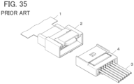
- JP 2007-214087 A discloses a connector as shown in FIG. 35 .
- This connector includes a first connector 2 connected to an end of a substrate 1 and a second connector 4 attached to tips of electric wires 3, and the electric wires 3 can be connected to a flexible conductor of the substrate 1 by fitting the second connector 4 to the first connector 2.
- first connector 2 and the second connector 4 that are separately attached to the end of the substrate 1 and the tips of the electric wires 3 need to be fitted to each other in order to connect the electric wires 3 to the flexible conductor of the substrate 1, and this causes a larger size of a device; and there is a separable connection portion between the first connector 2 and the second connector 4, which impairs the reliability of electric connection.
- the present invention has been made to solve the conventional problem as above and aims at providing a connector assembly that can electrically connect a conductor portion of an electric wire to a flexible conductor exposed on a surface of a sheet type conductive member with high reliability while its size can be reduced.
- the present invention also aims at providing a connecting method for electrically connecting a conductor portion of an electric wire to a flexible conductor exposed on a surface of a sheet type conductive member.
- a connector assembly according to the present invention comprises:
- a connecting method is one for connecting a conductor portion of an electric wire to a flexible conductor exposed on a surface of a sheet type conductive member, the method comprising:
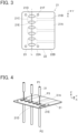
- FIG. 1 shows a connector assembly according to Embodiment 1.
- the connector assembly is obtained by connecting conductor portions 31A of a plurality of coated electric wires 31 to a sheet type conductive member 21 by means of a connector 11.
- the connector 11 includes a first insulator 12 and a second insulator 13 each made of an insulating resin material.
- the sheet type conductive member 21 is obtained by forming a plurality of flexible conductors 21B on a surface of a sheet type insulating base 21A.
- the flexible conductors 21B are aligned in a predetermined alignment direction, separately form linearly extending patterns, and are exposed on a surface of the sheet type conductive member 21.
- the coated electric wires 31 are aligned in the predetermined alignment direction as with the flexible conductors 21B of the sheet type conductive member 21, and each extend in parallel to the surface of the sheet type conductive member 21 and in a direction perpendicular to the alignment direction.
- Each coated electric wire 31 has a structure in which an outer periphery of the conductor portion 31A is covered with an insulating coating portion 31B. With the connector 11, the conductor portions 31A of the covered electric wires 31 are electrically connected to the flexible conductors 21B exposed on the surface of the sheet type conductive member 21.
- the conductor portion 31A of the coated electric wire 31 may be either a so-called solid wire constituted of one conductor or a so-called stranded wire constituted of plural conductors being stranded.
- the sheet type conductive member 21 is defined as extending along an XY plane, the predetermined alignment direction of the flexible conductors 21B and the coated electric wires 31 is referred to as "X direction,” the direction in which each coated electric wire 31 extends toward the connector 11 is referred to as "+Y direction,” and the direction orthogonal to an XY plane is referred to as "Z direction.”
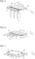
- FIG. 2 shows an assembly view of the connector assembly according to Embodiment 1.
- the sheet type conductive member 21 is disposed on the +Z direction side of the first insulator 12, and the second insulator 13 is disposed on the +Z direction side of the sheet type conductive member 21.
- coated electric wires 31 are each disposed in such a position as to extend in the Z direction on the -Y direction side of the sheet type conductive member 21.
- the first insulator 12 includes a flat plate portion 12A of rectangular shape extending along an XY plane, and a first retaining surface 12B of planar shape recessed in the -Z direction and facing in the +Z direction is formed at a +Y direction-side portion of the flat plate portion 12A.
- electric wire accommodating grooves 12C and 12D are formed on a -Y direction-side portion of the flat plate portion 12A, the electric wire accommodating grooves 12C extending in the Y direction from the first retaining surface 12B to a -Y directional end of the flat plate portion 12A, the electric wire accommodating grooves 12D being each disposed adjacent to the corresponding electric wire accommodating groove 12C on the +X direction side of the electric wire accommodating groove 12C, extending in the Y direction from the first retaining surface 12B, and terminating in front of the -Y directional end of the flat plate portion 12A.
- These electric wire accommodating grooves 12C and 12D are opened toward the +Z direction and each have a groove width and a groove depth that allow the insulating coating portion 31B of the coated electric wire 31 to be accommodated in the grooves 12C and 12D.
- the adjacent electric wire accommodating grooves 12C and 12D form a pair, and a plurality of the pairs of electric wire accommodating grooves 12C and 12D corresponding to the coated electric wires 31 are formed in the flat plate portion 12A.
- the flat plate portion 12A is provided with a plurality of bosses 12E projecting in the +Z direction.
- the second insulator 13 has a flat plate portion 13A of rectangular shape extending along an XY plane, and as with the first insulator 12, a second retaining surface of planar shape (not shown) recessed in the +Z direction and facing in the -Z direction is formed at a +Y direction-side portion of the flat plate portion 13A.
- electric wire accommodating grooves 13C and electric wire accommodating grooves not shown are formed at a -Y direction-side portion and in a surface, facing in the -Z direction, of the flat plate portion 31A, the electric wire accommodating grooves 13C extending in the Y direction from the second retaining surface to a -Y directional end of the flat plate portion 13A, the electric wire accommodating grooves not shown being each disposed adjacent to the corresponding electric wire accommodating groove 13C on the +X direction side of the electric wire accommodating groove 13C, extending in the Y direction from the second retaining surface, and terminating in front of the -Y directional end of the flat plate portion 13A.
- These electric wire accommodating grooves 13C and electric wire accommodating grooves not shown correspond to the electric wire accommodating grooves 12C and 12D of the first insulator 12, are opened toward the -Z direction, and each have a groove width and a groove depth that allow the insulating coating portion 31B of the coated electric wire 31 to be accommodated in the groove 13C and the groove not shown.
- the flat plate portion 13A is provided with a plurality of fixing holes 13E penetrating the flat plate portion 13A in the Z direction.
- the fixing holes 13E separately correspond to the bosses 12E of the first insulator 12.
- the coated electric wires 31 in assembling the connector assembly are each disposed in such a position as to extend in the Z direction such that a tip portion P1 faces in the +Z direction and that a base end portion P2 faces in the -Z direction.
- a conductor exposed portion P3 in which the conductor portion 31A is exposed over a predetermined Z directional length by removing the insulating coating portion 31B, is formed at a position away from the tip portion P1 of each coated electric wire 31 by a predetermined distance in the -Z direction.
- the sheet type conductive member 21 includes a first sheet portion 22 and a second sheet portion 23 disposed on the -Y direction side of the first sheet portion 22.
- a retained portion 22A is disposed at a -Y direction-side portion of the first sheet portion 22, and an extension portion 22B extending toward the +Y direction is disposed on the +Y direction side of the retained portion 22A.
- the second sheet portion 23 is joined to the retained portion 22A of the first sheet portion 22 via a folding-back line L extending in the X direction.
- the second sheet portion 23, the retained portion 22A, and the extension portion 22B are integrally formed continuously in the Y direction.
- the flexible conductors 21B exposed on the surface of the sheet type conductive member 21 on the +Z direction side are each disposed continuously from the second sheet portion 23 to the retained portion 22A and the extension portion 22B of the first sheet portion 22 beyond the folding-back line L.
- Each flexible conductor 21B has an electric wire connecting region 21C of substantially rectangular shape at a position overlapping the folding-back line L, and a pair of electric wire inserting holes 21D and 21E penetrating the sheet type conductive member 21 are separately formed on opposite sides in the X direction of the electric wire connecting region 21C on the folding-back line L.
- the pair of electric wire inserting holes 21D and 21E are each formed from a long hole that is sized so as to allow the insulating coating portion 31B of the coated electric wire 31 to pass through it.
- the pair of electric wire inserting holes 21D and 21E are separately situated to be in contact with the electric wire connecting region 21C on the opposite sides in the X direction of the electric wire connecting region 21C, and the flexible conductor 21B forming the electric wire connecting region 21C is disposed between the pair of electric wire inserting holes 21D and 21E.
- a plurality of the pairs of electric wire inserting holes 21D and 21E as above are formed in the sheet type conductive member 21 to correspond to the coated electric wires 31.
- a plurality of through-holes 21F corresponding to the plurality of bosses 12E of the first insulator 12 are formed in the retained portion 22A and the second sheet portion 23 of the sheet type conductive member 21.
- One through-hole 21F formed in the retained portion 22A and another through hole 21F formed in the second sheet portion 23 are arranged symmetrically with respect to the folding-back line L.
- each of the coated electric wires 31 is passed through the electric wire inserting hole 21D that is one of the corresponding pair of electric wire inserting holes 21D and 21E of the sheet type conductive member 21.
- the coated electric wire 31 is disposed such that a part thereof from the conductor exposed portion P3 to the tip portion P1 is situated on the +Z direction side of the sheet type conductive member 21 and that a part thereof on the base end portion P2 side of the conductor exposed portion P3 is situated on the -Z direction side of the sheet type conductive member 21.
- the conductor exposed portion P3 is bent, and the tip portion P1 of each of the coated electric wires 31 is passed through the electric wire inserting hole 21E that is the other of the corresponding pair of the electric wire inserting holes 21D and 21E from the +Z direction.
- the tip portion P1 of each of the coated electric wires 31 is situated on the -Z direction side of the sheet type conductive member 21, and the conductor portion 31A exposed at the conductor exposed portion P3 is situated between the pair of electric wire inserting holes 21D and 21E on the surface of the sheet type conductive member 21 on the +Z direction side.
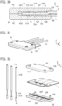
- the second sheet portion 23 of the sheet type conductive member 21 By folding back, in this state, the second sheet portion 23 of the sheet type conductive member 21 along the folding-back line L extending in the X direction that is the alignment direction of the coated electric wires 31 and the flexible conductors 21B, the second sheet portion 23 is rotated by 180 degrees around the folding-back line L so as to be superposed on the retained portion 22A of the first sheet portion 22 as shown in FIG. 6 .
- the coated electric wires 31 passed through the plurality of pairs of electric wire inserting holes 21D and 21E are rotated by 90 degrees around the folding-back line L, and the tip portion P1 and the base end portion P2 of each of the coated electric wires 31 extend from the sheet type conductive member 21 toward the -Y direction.
- the through-holes 21F separately formed in the retained portion 22A and the second sheet portion 23 are arranged symmetrically with respect to the folding-back line L, when the second sheet portion 23 is folded back around the folding-back line L, the through-hole 21F formed in the second sheet portion 23 is superposed on the through-hole 21F formed in the retained portion 22A.
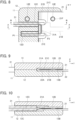
- the sheet type conductive member 21 is sandwiched between the first insulator 12 and the second insulator 13 as shown in FIG. 7 . Consequently, the retained portion 22A of the first sheet portion 22 of the sheet type conductive member 21 faces the first retaining surface 12B of the first insulator 12, and the second sheet portion 23 superposed on the retained portion 22A faces the second retaining surface of the second insulator 13.
- Tips of the bosses 12E projecting on the +Z direction side of the first insulator 13 are then thermally deformed, whereby the first insulator 12 and the second insulator 13 are fixed to each other to form the connector 11.
- the assembling operation of the connector assembly shown in FIG. 1 is completed.
- FIG. 8 shows the inside of the connector assembly. Since the electric wire connecting region 21C of the flexible conductor 21B is formed between the pair of the electric wire inserting holes 21D and 21E, with folding back of the second sheet portion 23, the flexible conductor 21B forming the electric wire connecting region 21C is folded in two parts, and the conductor portion 31A exposed at the conductor exposed portion P3 situated between the pair of electric wire inserting holes 21D and 21E is sandwiched between the two parts of the flexible conductor 21B thus folded as shown in FIG. 9 . In this manner, the flexible conductor 21B makes contact with the conductor portion 31A of the coated electric wire 31 with predetermined contact pressure and is electrically connected to the conductor portion 31A.
- the plurality of flexible conductors 21B are electrically connected separately to the conductor portions 31A of the plurality of coated electric wires 31.
- the retained portion 22A of the first sheet portion 22 and the second sheet portion 23 of the sheet type conductive member 21 being superposed on each other are sandwiched between the first retaining surface 12B of the first insulator 12 and the second retaining surface 13B of the second insulator 13.
- the tip portion P1 of the coated electric wire 31 projects in the -Y direction from the electric wire inserting hole 21E of the sheet type conductive member 21 and is accommodated in the electric wire accommodating groove 12D of the first insulator 12 and the electric wire accommodating groove not shown of the second insulator 13 in the connector 11.
- the part of the coated electric wire 31 on the base end portion P2 side projects in the -Y direction from the electric wire inserting hole 21D of the sheet type conductive member 21 and is accommodated in the electric wire accommodating groove 12C of the first insulator 12 and the electric wire accommodating groove 13C of the second insulator 13 and drawn from the connector 11 in the -Y direction as shown in FIG. 10 .
- the conductor portion 31A is sandwiched between the two parts of the flexible conductor 21B thus folded, thereby enabling to achieve a connector assembly that is small, specifically, thin, while electrically connecting the conductor portion 31A of the coated electric wire 31 to the flexible conductor 21B exposed on the surface of the sheet type conductive member 21 with high reliability.
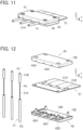
- FIG. 11 shows a connector assembly according to Embodiment 2.
- the connector assembly is obtained by connecting conductor portions 31A of a plurality of coated electric wires 31 to a sheet type conductive member 51 by means of a connector 41.
- the connector 41 includes a first insulator 42 and a second insulator 43 each made of an insulating resin material.
- FIG. 12 shows an assembly view of the connector assembly according to Embodiment 2.
- the first insulator 42 has the same configuration as that of the first insulator 12 used in Embodiment 1. That is, the second insulator 42 includes a flat plate portion 42A of rectangular shape extending along an XY plane, and the first retaining surface 12B facing in the +Z direction is formed at a +Y direction-side portion of the flat plate portion 42A.
- a plurality of electric wire accommodating grooves 42C and 42D extending to the inside of the first retaining surface 12B are formed at a -Y direction-side portion of the flat plate portion 42A as with the electric wire accommodating grooves 12C and 12D of the first insulator 12.
- the electric wire accommodating grooves 42C and 42D each have a groove width and a groove depth that allow the insulating coating portion 31B of the coated electric wire 31 to be accommodated in the grooves 42C and 42D.
- the flat plate portion 42A is provided with the plurality of bosses 12E.
- the second insulator 43 has the same configuration as that of the second insulator 13 used in Embodiment 1. That is, the second insulator 43 includes a flat plate portion 43A of rectangular shape extending along an XY plane, and a second retaining surface (not shown) facing in the -Z direction is formed at a +Y direction-side portion of the flat plate portion 43A. In addition, a plurality of electric wire accommodating grooves 43C and a plurality of electric wire accommodating grooves (not shown) corresponding to the electric wire accommodating grooves 42C and 42D of the first insulator 42 are formed at a -Y direction-side portion and in the surface, facing in the -Z direction, of the flat plate portion 43A.
- the electric wire accommodating grooves 43C and the electric wire accommodating groove not shown each have a groove width and a groove depth that allow the insulating coating portion 31B of the coated electric wire 31 to be accommodated in the groove 43C and the groove not shown.
- the flat plate portion 43A is provided with the plurality of fixing holes 13E.
- the sheet type conductive member 51 is obtained by forming the plurality of flexible conductors 21B on the surface of the sheet type insulating base 21A as with the sheet type conductive member 21 in Embodiment 1.
- the coated electric wires 31 herein have the same configuration as that of the coated electric wires 31 used in Embodiment 1 except that the coated electric wires 31 herein each have the conductor exposed portion P3 longer in the Z direction than the conductor exposed portion P3 in the coated electric wire 31 used in Embodiment 1.
- the sheet type conductive member 51 includes a first sheet portion 52 and a second sheet portion 53 disposed on the -Y direction side of the first sheet portion 52, a retained portion 52A is disposed at a -Y direction-side portion of the first sheet portion 52, and an extension portion 52B extending toward the +Y direction is formed on the +Y direction side of the retained portion 52A.
- the second sheet portion 53 is joined to the retained portion 52A of the first sheet portion 52 via the folding-back line L extending in the X direction.
- the flexible conductors 21B are formed only on a surface of the first sheet portion 52 on the +Z direction side and are not formed in the second sheet portion 53.
- Each flexible conductor 21B extends in the Y direction and is provided at its -Y directional end with an electric wire connecting region 51C of substantially rectangular shape disposed at the retained portion 52A.
- a pair of electric wire inserting holes 51D and 51E penetrating the sheet type conductive member 51 are formed on opposite sides in the X direction of the electric wire connecting region 51C near the folding-back line L.
- the pair of electric wire inserting holes 51D and 51E are disposed at positions inclined with respect to the folding-back line L, i.e., Y directional positions different from each other, and are each formed from a round hole that is sized so as to allow the insulating coating portion 31B of the coated electric wire 31 to pass through it.
- the pair of electric wire inserting holes 51D and 51E are each sized to allow the insulating coating portion 31B of the coated electric wire 31 to pass through it.
- the pair of electric wire inserting holes 51D and 51E are situated to be in contact with the electric wire connecting region 51C on the opposite sides in the X direction of the electric wire connecting region 51C, and the flexible conductor 21B forming the electric wire connecting region 51C is disposed between the pair of electric wire inserting holes 51D and 51E.
- a plurality of the pairs of electric wire inserting holes 51D and 51E as above are formed in the sheet type conductive member 51 to correspond to the coated electric wires 31.
- the retained portion 52A and the second sheet portion 53 of the sheet type conducive member 51 are provided with the plurality of through-holes 21F.
- each of the coated electric wires 31 is passed through the electric wire inserting hole 51D of the corresponding pair of the electric wire inserting holes 51D and 51E of the sheet type conductive member 51.
- the coated electric wire 31 is disposed such that a part thereof from the conductor exposed portion P3 to the tip portion P1 is situated on the +Z direction side of the sheet type conductive member 51 and that a part thereof on the base end portion P2 side of the conductor exposed portion P3 is situated on the -Z direction side of the sheet type conductive member 51.
- the conductor exposed portion P3 is bent, and the tip portion P1 of each of the coated electric wires 31 is passed through the electric wire inserting hole 51E that is the other of the corresponding pair of electric wire inserting holes 51D and 51E from the +Z direction.
- the tip portion P1 of each of the coated electric wires 31 is situated on the -Z direction side of the sheet type conductive member 51, and the conductor portion 31A exposed at the conductor exposed portion P3 is situated between the pair of electric wire inserting holes 51D and 51E on the surface of the sheet type conductive member 51 on the +Z direction side.
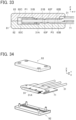
- the second sheet portion 53 of the sheet type conductive member 51 By folding back, in this state, the second sheet portion 53 of the sheet type conductive member 51 along the folding-back line L extending in X direction, as shown in FIG. 16 , the second sheet portion 53 is rotated by 180 degrees around the folding-back line L so as to be superposed on the retained portion 52A of the first sheet portion 52.
- the coated electric wires 31 passed through the plurality of pairs of electric wire inserting holes 51D and 51E are rotated by 90 degrees around the folding-back line L, and the tip portion P1 and the base end portion P2 of each of the coated electric wires 31 extend from the sheet type conductive member 51 toward the -Y direction.
- FIG. 18 shows the inside of the connector assembly. Since the electric wire connecting region 51C of the flexible conductor 21B is formed between the pair of electric wire inserting holes 51D and 51E, the conductor portion 31A exposed at the conductor exposed portion P3 situated between the pair of electric wire inserting holes 51D and 51E is disposed on the electric wire connecting region 51C, and as shown in FIG. 19 , with folding back of the second sheet portion 53, the retained portion 52A of the first sheet portion 52 and the second sheet portion 53 being superposed on each other are sandwiched between the first retaining surface 42B of the first insulator 42 and the second retaining surface 43B of the second insulator 43. In this manner, the flexible conductor 21B forming the electric wire connecting region 51C makes contact with the conductor portion 31A of the coated electric wire 31 with predetermined contact pressure and is electrically connected to the conductor portion 31A.
- the plurality of flexible conductors 21B are electrically connected separately to the conductor portions 31A of the plurality of coated electric wires 31.
- the tip portion P1 of the coated electric wire 31 projects in the -Y direction from the electric wire inserting hole 51E of the sheet type conductive member 51 and is accommodated in the electric wire accommodating groove 42D of the first insulator 42 and the electric wire accommodating groove 43D of the second insulator 43 in the connector 41.
- the part of the coated electric wire 31 on the base end portion P2 side projects in the -Y direction from the electric wire inserting hole 51D of the sheet type conductive member 51 and is accommodated in the electric wire accommodating groove 42C of the first insulator 42 and the electric wire accommodating groove 43C of the second insulator 43 and drawn from the connector 41 in the -Y direction as shown in FIG. 20 .
- the conductor portion 31A exposed at the conductor exposed portion P3 of the coated electric wire 31 makes contact with the electric wire connecting region 51C of the corresponding flexible conductor 21B, thereby enabling to achieve a connector assembly that is small, specifically, thin, while electrically connecting the conductor portion 31A of the coated electric wire 31 to the flexible conductor 21B exposed on the surface of the sheet type conductive member 51 with high reliability.
- the conductor portion 31A situated between the electric wire inserting holes 51D and 51E makes contact with the flexible conductor 21B over a distance longer than that in Embodiment 1, thereby improving the reliability of electrical connection.
- the electric wire inserting holes 51D and 51E of the sheet type conductive member 51 are disposed at the positions inclined with respect to the folding-back line L, so that the conductor portions 31A of the adjacent coated electric wires 31 are disposed with a distance therebetween in the Y direction, whereby short-circuit between the conductor portions 31A can be effectively prevented.
- the alignment pitch in the X direction of the coated electric wires 31 can also be narrowed.
- FIG. 21 shows a connector assembly according to Embodiment 3.
- the connector assembly is obtained by connecting conductor portions 31A of a plurality of coated electric wires 31 to a sheet type conductive member 71 by means of a connector 61.
- the connector 61 includes a first insulator 62 and a second insulator 63 each made of an insulating resin material.
- FIG. 22 shows an assembly view of the connector assembly according to Embodiment 3.
- the first insulator 62 includes a flat plate portion 62A of rectangular shape extending along an XY plane, and the first retaining surface 12B facing in the +Z direction is formed at a +Y direction-side portion of the flat plate portion 62A.
- a plurality of electric wire accommodating grooves 62C are formed at a -Y direction-side portion of the flat plate portion 62A to extend in the Y direction from the first retaining surface 12B and terminate in front of a -Y directional end of the flat plate portion 62A.
- the electric wire accommodating grooves 62C each have a groove width and a groove depth that allow the conductor portion 31A of the coated electric wire 31 to be accommodated in the groove 62C.
- the flat plate portion 62A is provided with the plurality of bosses 12E.
- a plurality of ribs 62F are formed on the first retaining surface 12B to extend in the X direction and project in the +Z direction.
- the second insulator 63 includes a flat plate portion 63A of rectangular shape extending along an XY plane, and a second retaining surface (not shown) facing in the -Z direction is formed at a +Y direction-side portion of the flat plate portion 63A.
- a plurality of electric wire accommodating grooves (not shown) corresponding to the plurality of electric wire accommodating grooves 62C of the first insulator 62 are formed at a -Y direction-side portion and in a surface, facing in the -Z direction, of the flat plate portion 63A.
- These electric wire accommodating grooves not shown each have a groove width and a groove depth that allow the conductor portion 31A of the coated electric wire 31 to be accommodated in the groove not shown.
- the flat plate portion 63A is provided with the plurality of fixing holes 13E.
- ribs are formed on the second retaining surface to extend in the X direction and project in the -Z direction.
- the sheet type conductive member 71 is obtained by forming the plurality of flexible conductors 21B on the surface of the sheet type insulating base 21A as with the sheet type conductive member 21 in Embodiment 1.
- the coated electric wires 31 in assembling the connector assembly are each disposed in such a position as to extend in the Z direction such that the tip portion P1 faces in the -Z direction and that the base end portion P2 faces in the +Z direction.
- the conductor exposed portion P3 is formed to extend from the tip portion P1 of each of the coated electric wires 31 in the +Z direction over a predetermined Z directional length.
- the insulating coating portion 31B is removed so that the conductor portion 31A is exposed.
- the sheet type conductive member 71 includes a first sheet portion 72 and a second sheet portion 73 disposed on the -Y direction side of the first sheet portion 72, a retained portion 72A is disposed in a -Y direction-side portion of the first sheet portion 72, and an extension portion 72B is formed on the +Y direction side of the retained portion 72A to extend toward the +Y direction.
- the second sheet portion 73 is joined to the retained portion 72A of the first sheet portion 72 via the folding-back line L extending in the X direction.
- the flexible conductors 21B are each disposed continuously from the second sheet portion 73 to the retained portion 72A and the extension portion 72B of the first sheet portion 72 beyond the folding-back line L.
- Each flexible conductor 21B has the electric wire connecting region 21C of substantially rectangular shape at a position overlapping the folding-back line L, and one electric wire inserting hole 71D penetrating the sheet type conductive member 71 is formed at a center part of the electric wire connecting region 21C situated on the folding-back line L.
- one electric wire guiding hole 71E is formed on the +X direction side of the electric wire connecting region 21C to penetrate the sheet type conductive member 71.
- the electric wire guiding hole 71E extends in the Y direction from the second sheet portion 73 to the retained portion 72A beyond the folding-back line L.
- a slit type communication opening portion 71F penetrating the sheet type conductive member 71 is formed between the electric wire inserting hole 71D and the electric wire guiding hole 71E such that the electric wire inserting hole 71D and the electric wire guiding hole 71E communicate with each other in the X direction along the folding-back line L.
- the electric wire inserting hole 71D is formed from a round hole having a size corresponding to the diameter of the conductor portion 31A of the coated electric wire 31, specifically, a diameter S1 slightly larger than the diameter of the conductor portion 31A.
- the electric wire guiding hole 71E is formed from a long hole having a width S2 substantially equal to the diameter S1 of the electric wire inserting hole 71D.
- the communication opening portion 71F has an opening width S3 having a dimension smaller than the diameter of the conductor portion 31A of the coated electric wire 31.
- the communication opening portion 71F is connected to the electric wire guiding hole 71E, whereby a T-shaped opening is formed in the sheet type conductive member 71 so as to be in contact with a pair of corner portions 71G constituted of the sheet type conductive member 71.
- the conductor portion 31A of the conductor exposed portion P3 formed at the tip portion P1 of each of the coated electric wires 31 is passed through the corresponding electric wire guiding hole 71E of the sheet type conductive member 71 from the +Z direction.
- the conductor portion 31A is passed through the electric wire guiding hole 71E such that -Z and +Z direction-side portions of the conductor exposed portion P3 are situated on the -Z and +Z direction sides of the sheet type conductive member 71, respectively.
- each of the coated electric wires 31 is slid in the -X direction relatively to the sheet type conductive member 71 along the corresponding communication opening portion 71F, whereby the conductor portion 31A exposed at the conductor exposed portion P3 of each of the coated electric wires 31 is passed through the corresponding electric wire inserting hole 71D.
- the communicating opening hole 71F has the opening width S3 having the dimension smaller than the diameter of the conductor portion 31A, part of the sheet type conductive member 71 around the communicating opening hole 71E is elastically bent, whereby the conductive portion 31A can be relatively slid to the electric wire inserting hole 71D.
- the second sheet portion 73 of the sheet type conductive member 71 By folding back, in this state, the second sheet portion 73 of the sheet type conductive member 71 along the folding-back line L extending in the X direction, the second sheet portion 73 is rotated by 180 degrees around the folding-back line L so as to be superposed on the retained portion 72A of the first sheet portion 72 as shown in FIG. 27 .
- the coated electric wires 31 having the conductor portions 31A passed through the electric wire inserting holes 71D are rotated by 90 degrees around the folding-back line L, the tip portion P1 of each of the coated electric wires 31 projects from the sheet type conductive member 71 toward the -Y direction, and the base end portion P2 extends from the sheet type conductive member 71 toward the +Y direction.
- the sheet type conductive member 71 is sandwiched between the first insulator 62 and the second insulator 63 as shown in FIG. 28 .
- Tips of the bosses 12E projecting on the +Z direction side of the second insulator 63 are then thermally deformed, whereby the first insulator 62 and the second insulator 63 are fixed to each other to form the connector 61.
- the assembling operation of the connector assembly shown in FIG. 21 is completed.
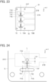
- FIG. 29 shows the inside of the connector assembly. Since the flexible conductor 21B has the electric wire connecting region 21C of substantially rectangular shape at the position overlapping the folding-back line L, with the second sheet portion 23 being folded back, the flexible conductor 21B forming the electric wire connecting region 21C is folded in two parts, and the conductor portion 31A exposed at the conductor exposed portion P3 of the coated electric wire 31 passed through the electric wire inserting hole 71D is sandwiched between the two parts of the flexible conductor 21B thus folded as shown in FIG. 30 . In this manner, the flexible conductor 21B forming the electric wire connecting region 21C makes contact with the conductor portion 31A of the coated electric wire 31 with predetermined contact pressure and is electrically connected to the conductor portion 31A.
- the plurality of flexible conductors 21B are electrically connected separately to the conductor portions 31A of the plurality of coated electric wires 31.
- the retained portion 72A of the first sheet portion 72 and the second sheet portion 73 of the sheet type conductive member 71 being superposed on each other are sandwiched between the first retaining surface 62B of the first insulator 62 and the second retaining surface 63B of the second insulator 63, and the flexible conductor 21B forming the electric wire connecting region 21C is tightly attached to the conductor portion 31A by means of the ribs 62F formed on the first retaining surface 62B and the ribs 63F formed on the second retaining surface 63B. This improves the reliability of electric connection between the flexible conductor 21B and the conductor portion 31A.
- the conductor portion 31A exposed at the tip portion P1 of the coated electric wire 31 projecting from the sheet type conductive member 71 toward the -Y direction is accommodated in the electric wire accommodating groove 62C of the first insulator 62 and the electric wire accommodating groove 63C of the second insulator 63 in the connector 61.
- a part of the coated electric wire 31 on the base end portion P2 side along with the sheet type conductive member 71 is drawn from the connector 61 in the +Y direction.
- the conductor portion 31A is bent in the Z direction at a +Y directional end of the connector 61, whereby the insulating coating portion 31B of the coated electric wire 31 is situated on a +Z directional surface of the extension portion 72B of the sheet type conductive member 71. That is, both the insulating coating portion 31B of the coated electric wire 31 and the extension portion 72B of the sheet type conductive member 71 can extend in the +Y direction without interfering with each other in the Z direction.
- the conductor portion 31A exposed at the conductor exposed portion P3 of the coated electric wire 31 makes contact with the electric wire connecting region 21C of the corresponding flexible conductor 21B, thereby enabling to achieve a connector assembly that is small, specifically, thin, while electrically connecting the conductor portion 31A of the coated electric wire 31 to the flexible conductor 21B exposed on the surface of the sheet type conductive member 71 with high reliability.
- the electric wire guiding hole 71E constituted of a long hole is formed to be connected to the electric wire inserting hole 71D of the sheet type conductive member 71 via the communication opening portion 71F, the conductor portion 31A of the coated electric wire 31 is passed through the electric wire guiding hole 71E and then slid along the communication opening portion 71F, whereby the conductor portion 31A can be passed through the electric wire inserting hole 71D, thus improving the operability in assembling the connector assembly.
- FIG. 31 shows a connector assembly according to Embodiment 4.
- the connector assembly is obtained by connecting conductor portions 31A of a plurality of coated electric wires 31 to a sheet type conductive member 71 by means of a connector 81.
- the connector 81 includes a first insulator 82 and a second insulator 83 each made of an insulating resin material.
- FIG. 32 shows an assembly view of the connector assembly according to Embodiment 4.
- the second insulator 83 is obtained by forming a plurality of electric wire accommodating grooves (not shown) in which the insulating coating portions 31B of the coated electric wires 31 are accommodated, instead of the plurality of electric wire accommodating grooves in which the conductor portions 31A of the coated electric wires 31 are accommodated, in the flat plate portion 63A in the second insulator 63 used in Embodiment 3, and otherwise has the same configuration as the second insulator 63 in Embodiment 3.
- the sheet type conductive member 71 herein is the same as that used in Embodiment 3.
- the coated electric wires 31 in assembling the connector assembly are each disposed in such a position as to extend in the Z direction such that the tip portion P1 faces in the -Z direction and that the base end portion P2 faces in the +Z direction.
- the insulating coating portion 31B is not removed and remains at the tip portion P1 of each coated electric wire 31, and the conductor exposed portion P3, in which the conductor portion 31A is exposed over a predetermined Z directional length by removing the insulating coating portion 31B, is formed at a position away from the tip portion P1 in the +Z direction by a predetermined distance.
- the conductor portion 31A of the conductor exposed portion P3 is then slid from the electric wire guiding hole 71E to the electric wire inserting hole 71D along the communication opening portion 71F, and the second sheet portion 73 of the sheet type conductive member 71 is folded back along the folding-back line L. In this manner, the tip portion P1 of each of the coated electric wires 31 projects from the sheet type conductive member 71 toward the -Y direction.
- the bosses 12E of the first insulator 82 are passed through the through-holes 21F of the sheet type conductive member 71 from the -Z direction and further passed through the fixing holes 13E of the second insulator 83, and the first insulator 82 and the second insulator 83 are fixed to each other to form the connector 81.
- the assembling operation of the connector assembly shown in FIG. 31 is completed.
- the conductor portion 31A exposed at the conductor exposed portion P3 of the coated electric wire 31 is sandwiched between the two parts of the flexible conductor 21B thus folded.
- the flexible conductor 21B is then tightly attached and electrically connected to the conductor portion 31A by the ribs 62F formed on the first retaining surface 62B of the first insulator 82 and the ribs 63F formed on the second retaining surface 63B of the second insulator 83.
- the plurality of flexible conductors 21B are electrically connected separately to the conductor portions 31A of the plurality of coated electric wires 31.
- the tip portion P1 of the coated electric wire 31 projecting from the sheet type conductive member 71 toward the -Y direction is accommodated in the electric wire accommodating groove 82C of the first insulator 82 and the electric wire accommodating groove 83C of the second insulator 83 in the connector 81.
- the conductor portion 31A exposed at the conductor exposed portion P3 of the coated electric wire 31 makes contact with the electric wire connecting region 21C of the corresponding flexible conductor 21B, thereby enabling to achieve a connector assembly that is small, specifically, thin, while electrically connecting the conductor portion 31A of the coated electric wire 31 to the flexible conductor 21B exposed on the surface of the sheet type conductive member 71 with high reliability.
- the conductor portion 31A at the tip portion P1 of the coated electric wire 31 projecting from the sheet type conductive member 71 toward the -Y direction is covered with the insulating coating portion 31B, short-circuit between the conductor portions 31A of the adjacent coated electric wires 31 can be prevented. Further, even when the conductor portion 31A is formed from a so-called stranded wire constituted of plural conductors being stranded, the insulating coating portion 31B covering the tip portion P1 of the coated electric wire 31 prevents a tip of the stranded wire from spreading, so that not only short-circuit due to the spread conductors is prevented, but also the handleability of the coated electric wire 31 is improved.
- the invention is not limited thereto, and one or more flexible conductor(s) 21B can be electrically connected to a conductor portion(s) 31A of one or more coated electric wire(s) 31 in a similar manner.
- the covered electric wire 31 is used as an electric wire to be connected to the flexible conductor 21B of the sheet type conductive member 21, 51, 71 in Embodiments 1 to 4 above, an electric wire formed of only the conductor portion 31A whose outer periphery is not covered with the insulating coating portion 31B may be connected to the flexible conductor 21B of the sheet type conductive member 21, 51, 71.
Landscapes
- Engineering & Computer Science (AREA)
- Manufacturing & Machinery (AREA)
- Microelectronics & Electronic Packaging (AREA)
- Coupling Device And Connection With Printed Circuit (AREA)
- Multi-Conductor Connections (AREA)
Claims (18)
- Verbinderanordnung, umfassend:ein flachmaterialartiges leitfähiges Element (21, 51, 71), das einen flexiblen Leiter (21B) aufweist, der an einer Fläche des flachmaterialartigen leitfähigen Elements frei liegt;einen elektrischen Draht (31), der einen Leiterabschnitt (31A) aufweist; undeinen Verbinder (11, 41, 61, 81), der den Leiterabschnitt mit dem flexiblen Leiter verbindet,wobei der Verbinder einen ersten Isolator (12, 42, 62, 82, 92), der eine erste Haltefläche (12B) aufweist, und einen zweiten Isolator (13, 43, 63, 83, 93), der eine zweite Haltefläche (13B) aufweist, die der ersten Haltefläche zugewandt ist, aufweist,wobei das flachmaterialartige leitfähige Element einen ersten Flachmaterialabschnitt (22, 52, 72) aufweist, der einen gehaltenen Abschnitt (22A, 52A, 72A) aufweist, der so angeordnet ist, dass er der ersten Haltefläche zugewandt ist, einen zweiten Flachmaterialabschnitt (23, 53, 73) aufweist, der mit dem gehaltenen Abschnitt über eine Zurückfaltlinie (L) verbunden und so angeordnet ist, dass er der zweiten Haltefläche zugewandt ist, wobei der zweite Flachmaterialabschnitt entlang der Zurückfaltlinie an den gehaltenen Abschnitt zurückgefaltet ist, und wenigstens ein Einführloch (21D, 21E, 51D, 51E, 71D) für einen elektrischen Draht aufweist, das in wenigstens einem des gehaltenen Abschnitts und des zweiten Flachmaterialabschnitt gebildet ist und durch das flachmaterialartige leitfähige Element hindurch verläuft,wobei der flexible Leiter wenigstens an einer Fläche des gehaltenen Abschnitts frei liegt,wobei der Leiterabschnitt des elektrischen Drahtes durch das Einführloch für einen elektrischen Draht geführt und zwischen dem gehaltenen Abschnitt und dem zweiten Flachmaterialabschnitt angeordnet ist, undwobei der erste Isolator und der zweite Isolator so aneinander befestigt sind, dass der gehaltene Abschnitt und der zweite Flachmaterialabschnitt übereinander liegen und zwischen der ersten Haltefläche und der zweiten Haltefläche angeordnet sind, wodurch der flexible Leiter (21B) mit dem Leiterabschnitt (31A) des elektrischen Drahtes in Kontakt kommt und mit diesem Leiterabschnitt (31A) elektrisch verbunden ist.
- Verbinderanordnung nach Anspruch 1,wobei der erste Flachmaterialabschnitt (22, 52, 72) einen Verlängerungsabschnitt (22B, 52B, 72B) aufweist, der sich von dem gehaltenen Abschnitt (22A, 52A, 72A) zu einer Außenseite des Verbinders entlang einer zuvor festgelegten Richtung erstreckt, undwobei der flexible Leiter (21B) durchgehend von dem gehaltenen Abschnitt zu dem Verlängerungsabschnitt angeordnet ist.
- Verbinderanordnung nach Anspruch 2,wobei das flachmaterialartige leitfähige Element (21, 51) ein Paar der Einführlöcher (21D, 21E, 51D, 51E) für einen elektrischen Draht aufweist, die jeweils durch das flachmaterialartige leitfähige Element hindurch verlaufen, wobei der flexible Leiter (21B) zwischen dem Paar der Einführlöcher für einen elektrischen Draht angeordnet ist, undwobei der elektrische Draht (31) nacheinander durch das Paar der Einführlöcher für einen elektrischen Draht geführt ist und der Leiterabschnitt (31A) des elektrischen Drahtes, der sich zwischen dem Paar der Einführlöcher für einen elektrischen Draht befindet, elektrisch mit dem flexiblen Leiter (21B) verbunden ist.
- Verbinderanordnung nach Anspruch 3,wobei der flexible Leiter (21B) durchgehend von dem zweiten Flachmaterialabschnitt (23) zu dem gehaltenen Abschnitt (22A) und dem Verlängerungsabschnitt (22B) über die Zurückfaltlinie (L) hinaus angeordnet und in zwei Teile entlang der Zurückfaltlinie gefaltet ist, undwobei der Leiterabschnitt (31A) des elektrischen Drahtes, der sich zwischen dem Paar der Einführlöcher für den elektrischen Leiter befindet, zwischen den zwei Teilen des auf diese Weise gefalteten flexiblen Leiters angeordnet und elektrisch mit dem flexiblen Leiter (21B) verbunden ist.
- Verbinderanordnung nach Anspruch 4, wobei das Paar der Einführlöcher (21D, 21E) für einen elektrischen Draht an der Zurückfaltlinie (L) angeordnet ist.
- Verbinderanordnung nach Anspruch 3, wobei das Paar der Einführlöcher (51D, 51E) für einen elektrischen Draht innerhalb des gehaltenen Abschnitts (52A) und separat an Positionen angeordnet ist, die in Bezug auf die Zurückfaltlinie (L) geneigt sind.
- Verbinderanordnung nach Anspruch 3,wobei ein Spitzenabschnitt (P1) des elektrischen Drahtes (31), der nacheinander durch das Paar der Einführlöcher (21D, 21E, 51D, 51E) für einen elektrischen Draht geführt ist, zwischen dem ersten Isolator (12, 42) und dem zweiten Isolator (13, 43) aufgenommen ist, undwobei sich ein Basisendabschnitt (P2) des elektrischen Drahtes (31), der nacheinander durch das Paar der Einführlöcher für einen elektrischen Draht geführt ist, zur Außenseite des Verbinders (11, 41) erstreckt.
- Verbinderanordnung nach Anspruch 3,wobei der elektrische Draht (31) eine Struktur aufweist, bei der ein Außenumfang des Leiterabschnitts (31A) mit einem isolierenden Beschichtungsabschnitt (31B) überzogen ist,wobei, zwischen dem Paar der Einführlöcher (21D, 21E, 51D, 51E) für einen elektrischen Draht, der isolierende Beschichtungsabschnitt von dem elektrischen Draht entfernt ist, so dass der Leiterabschnitt (31A) frei liegt, undwobei, an einer anderen Position als zwischen dem Paar der Einführlöcher für einen elektrischen Draht, ein Außenumfang des Leiterabschnitts (31A) des elektrischen Drahtes mit dem isolierenden Beschichtungsabschnitt (31B) überzogen ist.
- Verbinderanordnung nach Anspruch 2,wobei das flachmaterialartige leitfähige Element (71) das Einführloch (71D) für einen elektrischen Draht aufweist, das durch das flachmaterialartige leitfähige Element an der Zurückfaltlinie (L) und an einer Position, an der der flexible Leiter (21B) frei liegt, hindurch verläuft,wobei der flexible Leiter (21B) durchgehend von dem zweiten Flachmaterialabschnitt zu dem gehaltenen Abschnitt und dem Verlängerungsabschnitt über die Zurückfaltlinie (L) hinaus angeordnet und in zwei Teile entlang der Zurückfaltlinie gefaltet ist,wobei der elektrische Draht (31) durch das Einführloch für einen elektrischen Draht geführt ist, undwobei der Leiterabschnitt (31A) des elektrischen Drahtes, der zwischen den zwei Teilen des auf diese Weise gefalteten flexiblen Leiters angeordnet ist, elektrisch mit dem flexiblen Leiter (21B) verbunden ist.
- Verbinderanordnung nach Anspruch 9,wobei das flachmaterialartige leitfähige Element (71) aufweist: ein Führungsloch (71E) für einen elektrischen Draht, das in der Nähe des Einführlochs für einen elektrischen Draht angeordnet ist und durch das flachmaterialartige leitfähige Element hindurch verläuft;und einen Verbindungsöffnungsabschnitt (71F), der das Einführloch für einen elektrischen Draht und das Führungsloch für einen elektrischen Draht miteinander in Verbindung setzt und durch das flachmaterialartige leitfähige Element hindurch verläuft,wobei das Einführloch (71D) für einen elektrischen Draht aus einem runden Loch gebildet ist, das einen Durchmesser (S1) aufweist, der einem Durchmesser des Leiterabschnitts des elektrischen Drahtes entspricht,wobei das Führungsloch (71E) für einen elektrischen Draht aus einem Langloch gebildet ist, das eine Breite (S2) aufweist, die im Wesentlichen gleich dem Durchmesser des Einführlochs für einen elektrischen Draht ist, undwobei der Verbindungsöffnungsabschnitt (71F) eine Öffnungsbreite (S3) aufweist, die eine Abmessung aufweist, die kleiner ist als der Durchmesser des Leiterabschnitts des elektrischen Drahtes.
- Verbinderanordnung nach Anspruch 9, wobei wenigstens eine der ersten Haltefläche (12B) und der zweiten Haltefläche (13B) eine Rippe (62F, 63F) aufweist, um den flexiblen Leiter fest an dem Leiterabschnitt des elektrischen Drahtes anzubringen.
- Verbinderanordnung nach Anspruch 9,wobei der elektrische Draht (31) eine Struktur aufweist, bei der ein Außenumfang des Leiterabschnitts (31A) mit einem isolierenden Beschichtungsabschnitt (31B) überzogen ist, undwobei, zwischen den zwei Teilen des auf diese Weise gefalteten flexiblen Leiters (21B), der isolierende Beschichtungsabschnitt von dem elektrischen Draht entfernt wird, so dass der Leiterabschnitt (31A) frei liegt.
- Verbinderanordnung nach Anspruch 12, wobei der elektrische Draht (31) einen Spitzenabschnitt (P1) aufweist, der von dem Einführloch (71D) für einen elektrischen Draht in Richtung einer Außenseite des flachmaterialartigen leitfähigen Elements (71) vorsteht und der zwischen dem ersten Isolator (82, 92) und dem zweiten Isolator (83, 93) aufgenommen ist.
- Verbinderanordnung nach Anspruch 13, wobei, an dem Spitzenabschnitt (P1), der isolierende Beschichtungsabschnitt von dem elektrischen Draht entfernt ist, so dass der Leiterabschnitt (31A) frei liegt.
- Verbinderanordnung nach Anspruch 13, wobei, an dem Spitzenabschnitt (P1), ein Außenumfang des Leiterabschnitts (31A) des elektrischen Drahtes mit dem isolierenden Beschichtungsabschnitt (31B) oder einem Isolierband (91) überzogen ist.
- Verbinderanordnung nach Anspruch 1, wobei ein Höcker (12E), der an einer der ersten Haltefläche und der zweiten Haltefläche gebildet ist, in ein Befestigungsloch (13E) eingeführt ist, das in einer anderen der ersten Haltefläche und der zweiten Haltefläche gebildet ist, wodurch der erste Isolator (12, 42, 62, 82, 92) und der zweite Isolator (13, 43, 63, 83, 93) aneinander befestigt sind.
- Verbinderanordnung nach Anspruch 1,wobei das flachmaterialartige leitfähige Element (21, 51, 71) mehrere der flexiblen Leiter (21B) aufweist, die in einer zuvor festgelegten Richtung entlang der Zurückfaltlinie (L) ausgerichtet sind, undwobei die mehreren der flexiblen Leiter (21B) separat elektrisch mit den Leiterabschnitten (31A) von mehreren der elektrischen Drähte, die in der zuvor festgelegten Richtung ausgerichtet sind, verbunden sind.
- Verbindungsverfahren zum Verbinden eines Leiterabschnitts (31A) eines elektrischen Drahtes (31) mit einem flexiblen Leiter (21B), der an einer Fläche eines flachmaterialartigen leitfähigen Elements (21, 51, 71) frei liegt, wobei das Verfahren umfasst:Hindurchführen des Leiterabschnitts (31A) des elektrischen Drahtes durch wenigstens ein Einführloch (21D, 21E, 51D, 51E, 71D) für einen elektrischen Draht, das in wenigstens einem von einem gehaltenen Abschnitt (22A, 52A, 72A) und einem zweiten Flachmaterialabschnitt (23, 53, 73) in dem flachmaterialartigen leitfähigen Element gebildet ist, das einen ersten Flachmaterialabschnitt (22, 52, 72) und den zweiten Flachmaterialabschnitt aufweist, der mit dem gehaltenen Abschnitt des ersten Flachmaterialabschnitts über eine Zurückfaltlinie (L) verbunden wird, wobei das wenigstens eine Einführloch für einen elektrischen Draht durch das flachmaterialartige leitfähige Element hindurch verläuft,Zurückfalten des zweiten Flachmaterialabschnitts (23, 53, 73) an den gehaltenen Abschnitt (22A, 52A, 72A) entlang der Zurückfaltlinie so, dass der Leiterabschnitt (31A) des elektrischen Drahtes zwischen dem gehaltenen Abschnitt und dem zweiten Flachmaterialabschnitt angeordnet ist, undBefestigen des ersten Isolators und des zweiten Isolators aneinander, wobei der gehaltene Abschnitt (22A, 52A, 72A) und der zweite Flachmaterialabschnitt (23, 53, 73) zwischen einer ersten Haltefläche (12B) des ersten Isolators und einer zweiten Haltefläche (13B) des zweiten Isolators sandwichartig aufgenommen werden, wodurch der flexible Leiter (21B) mit dem Leiterabschnitt (31A) des elektrischen Drahtes in Kontakt kommt und mit diesem Leiterabschnitt (31A) elektrisch verbunden wird.
Applications Claiming Priority (1)
| Application Number | Priority Date | Filing Date | Title |
|---|---|---|---|
| JP2022191896A JP2024079143A (ja) | 2022-11-30 | 2022-11-30 | コネクタ組立体および接続方法 |
Publications (2)
| Publication Number | Publication Date |
|---|---|
| EP4379964A1 EP4379964A1 (de) | 2024-06-05 |
| EP4379964B1 true EP4379964B1 (de) | 2025-04-30 |
Family
ID=88586614
Family Applications (1)
| Application Number | Title | Priority Date | Filing Date |
|---|---|---|---|
| EP23205196.1A Active EP4379964B1 (de) | 2022-11-30 | 2023-10-23 | Verbinderanordnung und verbindungsverfahren |
Country Status (4)
| Country | Link |
|---|---|
| US (1) | US12482964B2 (de) |
| EP (1) | EP4379964B1 (de) |
| JP (1) | JP2024079143A (de) |
| CN (1) | CN118117363A (de) |
Citations (2)
| Publication number | Priority date | Publication date | Assignee | Title |
|---|---|---|---|---|
| JP2874405B2 (ja) * | 1991-09-10 | 1999-03-24 | 住友電装株式会社 | フラットケーブルの接続方法 |
| EP4379963A1 (de) * | 2022-11-30 | 2024-06-05 | Japan Aviation Electronics Industry, Limited | Verbinderanordnung und verbindungsverfahren |
Family Cites Families (8)
| Publication number | Priority date | Publication date | Assignee | Title |
|---|---|---|---|---|
| US5030794A (en) * | 1990-02-14 | 1991-07-09 | Rlp Tool Co. | Accessory RF shields for multiple-line ribbon cables |
| JPH11312568A (ja) * | 1998-04-27 | 1999-11-09 | Yazaki Corp | ステアリング用電気的接続装置における電線とフラットケーブルの接続コネクタ |
| JP2004063280A (ja) | 2002-07-29 | 2004-02-26 | Furukawa Electric Co Ltd:The | 平型配線材とフレキシブルプリント配線材の接続構造及びその製造方法 |
| JP2007214087A (ja) | 2006-02-13 | 2007-08-23 | Fujikura Ltd | コネクタ |
| JP6024650B2 (ja) * | 2013-08-12 | 2016-11-16 | 株式会社オートネットワーク技術研究所 | 金具付導電シート |
| JP6562886B2 (ja) * | 2016-10-27 | 2019-08-21 | 矢崎総業株式会社 | 分岐構造及びワイヤハーネス |
| JP7313991B2 (ja) * | 2019-09-09 | 2023-07-25 | 日本航空電子工業株式会社 | コネクタ |
| JP7419920B2 (ja) * | 2020-03-26 | 2024-01-23 | 株式会社オートネットワーク技術研究所 | 配線部材 |
-
2022
- 2022-11-30 JP JP2022191896A patent/JP2024079143A/ja active Pending
-
2023
- 2023-09-20 CN CN202311218347.9A patent/CN118117363A/zh active Pending
- 2023-10-04 US US18/480,715 patent/US12482964B2/en active Active
- 2023-10-23 EP EP23205196.1A patent/EP4379964B1/de active Active
Patent Citations (2)
| Publication number | Priority date | Publication date | Assignee | Title |
|---|---|---|---|---|
| JP2874405B2 (ja) * | 1991-09-10 | 1999-03-24 | 住友電装株式会社 | フラットケーブルの接続方法 |
| EP4379963A1 (de) * | 2022-11-30 | 2024-06-05 | Japan Aviation Electronics Industry, Limited | Verbinderanordnung und verbindungsverfahren |
Also Published As
| Publication number | Publication date |
|---|---|
| US12482964B2 (en) | 2025-11-25 |
| US20240178591A1 (en) | 2024-05-30 |
| JP2024079143A (ja) | 2024-06-11 |
| EP4379964A1 (de) | 2024-06-05 |
| CN118117363A (zh) | 2024-05-31 |
Similar Documents
| Publication | Publication Date | Title |
|---|---|---|
| EP3376601B1 (de) | Verbinder | |
| EP3435490B1 (de) | Verbindungsunterstützungselement und leiterplattenanordnung | |
| EP4346017B1 (de) | Verbinder | |
| EP4300713B1 (de) | Blattartiges leitfähiges element und verbinder | |
| EP4213308B1 (de) | Verbinder | |
| CN201160128Y (zh) | 电连接器 | |
| EP4379964B1 (de) | Verbinderanordnung und verbindungsverfahren | |
| US12230907B2 (en) | Electrical connector for connecting an electric wire to a flat flexible conductor and an electrical connector assembly therefor | |
| EP4462605B1 (de) | Verbinder | |
| US12567689B2 (en) | Connector assembly and connecting method | |
| US10862254B2 (en) | Coated conductive wire connecting method, coated conductive wire connecting structure and coated conductive wire connecting member | |
| JP2001060469A (ja) | フラットケーブルの接続構造 | |
| EP4346013B1 (de) | Verbinder, verbinderanordnung und verbindungsverfahren | |
| EP4362233B1 (de) | Verbinder und verbinderanordnung | |
| EP4343974B1 (de) | Verbinder | |
| EP4478554B1 (de) | Verbinder und verbinderanordnung | |
| EP4387004B1 (de) | Verbinder | |
| US20240088590A1 (en) | Connector | |
| EP4376225B1 (de) | Verbinder | |
| EP4418467B1 (de) | Verbinder und verbinderanordnung | |
| EP4333216A1 (de) | Verbinder | |
| JPH07153532A (ja) | フレキケーブル接続装置 |
Legal Events
| Date | Code | Title | Description |
|---|---|---|---|
| PUAI | Public reference made under article 153(3) epc to a published international application that has entered the european phase |
Free format text: ORIGINAL CODE: 0009012 |
|
| STAA | Information on the status of an ep patent application or granted ep patent |
Free format text: STATUS: REQUEST FOR EXAMINATION WAS MADE |
|
| 17P | Request for examination filed |
Effective date: 20231023 |
|
| AK | Designated contracting states |
Kind code of ref document: A1 Designated state(s): AL AT BE BG CH CY CZ DE DK EE ES FI FR GB GR HR HU IE IS IT LI LT LU LV MC ME MK MT NL NO PL PT RO RS SE SI SK SM TR |
|
| RBV | Designated contracting states (corrected) |
Designated state(s): AL AT BE BG CH CY CZ DE DK EE ES FI FR GB GR HR HU IE IS IT LI LT LU LV MC ME MK MT NL NO PL PT RO RS SE SI SK SM TR |
|
| STAA | Information on the status of an ep patent application or granted ep patent |
Free format text: STATUS: EXAMINATION IS IN PROGRESS |
|
| 17Q | First examination report despatched |
Effective date: 20240927 |
|
| GRAP | Despatch of communication of intention to grant a patent |
Free format text: ORIGINAL CODE: EPIDOSNIGR1 |
|
| STAA | Information on the status of an ep patent application or granted ep patent |
Free format text: STATUS: GRANT OF PATENT IS INTENDED |
|
| RIC1 | Information provided on ipc code assigned before grant |
Ipc: H01R 12/70 20110101ALN20250121BHEP Ipc: H05K 1/18 20060101ALI20250121BHEP Ipc: H01R 12/63 20110101AFI20250121BHEP |
|
| INTG | Intention to grant announced |
Effective date: 20250204 |
|
| GRAS | Grant fee paid |
Free format text: ORIGINAL CODE: EPIDOSNIGR3 |
|
| GRAA | (expected) grant |
Free format text: ORIGINAL CODE: 0009210 |
|
| STAA | Information on the status of an ep patent application or granted ep patent |
Free format text: STATUS: THE PATENT HAS BEEN GRANTED |
|
| AK | Designated contracting states |
Kind code of ref document: B1 Designated state(s): AL AT BE BG CH CY CZ DE DK EE ES FI FR GB GR HR HU IE IS IT LI LT LU LV MC ME MK MT NL NO PL PT RO RS SE SI SK SM TR |
|
| REG | Reference to a national code |
Ref country code: CH Ref legal event code: EP Ref country code: GB Ref legal event code: FG4D |
|
| REG | Reference to a national code |
Ref country code: DE Ref legal event code: R096 Ref document number: 602023003203 Country of ref document: DE |
|
| REG | Reference to a national code |
Ref country code: IE Ref legal event code: FG4D |
|
| REG | Reference to a national code |
Ref country code: NL Ref legal event code: MP Effective date: 20250430 |
|
| REG | Reference to a national code |
Ref country code: AT Ref legal event code: MK05 Ref document number: 1790986 Country of ref document: AT Kind code of ref document: T Effective date: 20250430 |
|
| PG25 | Lapsed in a contracting state [announced via postgrant information from national office to epo] |
Ref country code: PT Free format text: LAPSE BECAUSE OF FAILURE TO SUBMIT A TRANSLATION OF THE DESCRIPTION OR TO PAY THE FEE WITHIN THE PRESCRIBED TIME-LIMIT Effective date: 20250901 Ref country code: FI Free format text: LAPSE BECAUSE OF FAILURE TO SUBMIT A TRANSLATION OF THE DESCRIPTION OR TO PAY THE FEE WITHIN THE PRESCRIBED TIME-LIMIT Effective date: 20250430 Ref country code: ES Free format text: LAPSE BECAUSE OF FAILURE TO SUBMIT A TRANSLATION OF THE DESCRIPTION OR TO PAY THE FEE WITHIN THE PRESCRIBED TIME-LIMIT Effective date: 20250430 |
|
| REG | Reference to a national code |
Ref country code: LT Ref legal event code: MG9D |
|
| PG25 | Lapsed in a contracting state [announced via postgrant information from national office to epo] |
Ref country code: NO Free format text: LAPSE BECAUSE OF FAILURE TO SUBMIT A TRANSLATION OF THE DESCRIPTION OR TO PAY THE FEE WITHIN THE PRESCRIBED TIME-LIMIT Effective date: 20250730 Ref country code: GR Free format text: LAPSE BECAUSE OF FAILURE TO SUBMIT A TRANSLATION OF THE DESCRIPTION OR TO PAY THE FEE WITHIN THE PRESCRIBED TIME-LIMIT Effective date: 20250731 |
|
| PG25 | Lapsed in a contracting state [announced via postgrant information from national office to epo] |
Ref country code: NL Free format text: LAPSE BECAUSE OF FAILURE TO SUBMIT A TRANSLATION OF THE DESCRIPTION OR TO PAY THE FEE WITHIN THE PRESCRIBED TIME-LIMIT Effective date: 20250430 Ref country code: PL Free format text: LAPSE BECAUSE OF FAILURE TO SUBMIT A TRANSLATION OF THE DESCRIPTION OR TO PAY THE FEE WITHIN THE PRESCRIBED TIME-LIMIT Effective date: 20250430 |
|
| PG25 | Lapsed in a contracting state [announced via postgrant information from national office to epo] |
Ref country code: BG Free format text: LAPSE BECAUSE OF FAILURE TO SUBMIT A TRANSLATION OF THE DESCRIPTION OR TO PAY THE FEE WITHIN THE PRESCRIBED TIME-LIMIT Effective date: 20250430 |
|
| PG25 | Lapsed in a contracting state [announced via postgrant information from national office to epo] |
Ref country code: HR Free format text: LAPSE BECAUSE OF FAILURE TO SUBMIT A TRANSLATION OF THE DESCRIPTION OR TO PAY THE FEE WITHIN THE PRESCRIBED TIME-LIMIT Effective date: 20250430 |
|
| PG25 | Lapsed in a contracting state [announced via postgrant information from national office to epo] |
Ref country code: AT Free format text: LAPSE BECAUSE OF FAILURE TO SUBMIT A TRANSLATION OF THE DESCRIPTION OR TO PAY THE FEE WITHIN THE PRESCRIBED TIME-LIMIT Effective date: 20250430 |
|
| PG25 | Lapsed in a contracting state [announced via postgrant information from national office to epo] |
Ref country code: RS Free format text: LAPSE BECAUSE OF FAILURE TO SUBMIT A TRANSLATION OF THE DESCRIPTION OR TO PAY THE FEE WITHIN THE PRESCRIBED TIME-LIMIT Effective date: 20250731 |
|
| PG25 | Lapsed in a contracting state [announced via postgrant information from national office to epo] |
Ref country code: IS Free format text: LAPSE BECAUSE OF FAILURE TO SUBMIT A TRANSLATION OF THE DESCRIPTION OR TO PAY THE FEE WITHIN THE PRESCRIBED TIME-LIMIT Effective date: 20250830 |
|
| PG25 | Lapsed in a contracting state [announced via postgrant information from national office to epo] |
Ref country code: LV Free format text: LAPSE BECAUSE OF FAILURE TO SUBMIT A TRANSLATION OF THE DESCRIPTION OR TO PAY THE FEE WITHIN THE PRESCRIBED TIME-LIMIT Effective date: 20250430 |
|
| PGFP | Annual fee paid to national office [announced via postgrant information from national office to epo] |
Ref country code: DE Payment date: 20251015 Year of fee payment: 3 |
|
| PG25 | Lapsed in a contracting state [announced via postgrant information from national office to epo] |
Ref country code: SM Free format text: LAPSE BECAUSE OF FAILURE TO SUBMIT A TRANSLATION OF THE DESCRIPTION OR TO PAY THE FEE WITHIN THE PRESCRIBED TIME-LIMIT Effective date: 20250430 Ref country code: DK Free format text: LAPSE BECAUSE OF FAILURE TO SUBMIT A TRANSLATION OF THE DESCRIPTION OR TO PAY THE FEE WITHIN THE PRESCRIBED TIME-LIMIT Effective date: 20250430 |
|
| PGFP | Annual fee paid to national office [announced via postgrant information from national office to epo] |
Ref country code: FR Payment date: 20251030 Year of fee payment: 3 |
|
| PG25 | Lapsed in a contracting state [announced via postgrant information from national office to epo] |
Ref country code: CZ Free format text: LAPSE BECAUSE OF FAILURE TO SUBMIT A TRANSLATION OF THE DESCRIPTION OR TO PAY THE FEE WITHIN THE PRESCRIBED TIME-LIMIT Effective date: 20250430 |
|
| PG25 | Lapsed in a contracting state [announced via postgrant information from national office to epo] |
Ref country code: EE Free format text: LAPSE BECAUSE OF FAILURE TO SUBMIT A TRANSLATION OF THE DESCRIPTION OR TO PAY THE FEE WITHIN THE PRESCRIBED TIME-LIMIT Effective date: 20250430 |
|
| PG25 | Lapsed in a contracting state [announced via postgrant information from national office to epo] |
Ref country code: SK Free format text: LAPSE BECAUSE OF FAILURE TO SUBMIT A TRANSLATION OF THE DESCRIPTION OR TO PAY THE FEE WITHIN THE PRESCRIBED TIME-LIMIT Effective date: 20250430 |
|
| PG25 | Lapsed in a contracting state [announced via postgrant information from national office to epo] |
Ref country code: IT Free format text: LAPSE BECAUSE OF FAILURE TO SUBMIT A TRANSLATION OF THE DESCRIPTION OR TO PAY THE FEE WITHIN THE PRESCRIBED TIME-LIMIT Effective date: 20250430 |
|
| REG | Reference to a national code |
Ref country code: DE Ref legal event code: R097 Ref document number: 602023003203 Country of ref document: DE |
|
| PG25 | Lapsed in a contracting state [announced via postgrant information from national office to epo] |
Ref country code: RO Free format text: LAPSE BECAUSE OF FAILURE TO SUBMIT A TRANSLATION OF THE DESCRIPTION OR TO PAY THE FEE WITHIN THE PRESCRIBED TIME-LIMIT Effective date: 20250430 |
|
| PLBE | No opposition filed within time limit |
Free format text: ORIGINAL CODE: 0009261 |
|
| STAA | Information on the status of an ep patent application or granted ep patent |
Free format text: STATUS: NO OPPOSITION FILED WITHIN TIME LIMIT |
|
| REG | Reference to a national code |
Ref country code: CH Ref legal event code: L10 Free format text: ST27 STATUS EVENT CODE: U-0-0-L10-L00 (AS PROVIDED BY THE NATIONAL OFFICE) Effective date: 20260311 |