EP4375138A1 - Sitzkopfstütze und fahrzeugsitz - Google Patents
Sitzkopfstütze und fahrzeugsitz Download PDFInfo
- Publication number
- EP4375138A1 EP4375138A1 EP22844855.1A EP22844855A EP4375138A1 EP 4375138 A1 EP4375138 A1 EP 4375138A1 EP 22844855 A EP22844855 A EP 22844855A EP 4375138 A1 EP4375138 A1 EP 4375138A1
- Authority
- EP
- European Patent Office
- Prior art keywords
- headrest
- seat
- pinion
- rack
- slider
- Prior art date
- Legal status (The legal status is an assumption and is not a legal conclusion. Google has not performed a legal analysis and makes no representation as to the accuracy of the status listed.)
- Pending
Links
Images


Classifications
-
- B—PERFORMING OPERATIONS; TRANSPORTING
- B60—VEHICLES IN GENERAL
- B60N—SEATS SPECIALLY ADAPTED FOR VEHICLES; VEHICLE PASSENGER ACCOMMODATION NOT OTHERWISE PROVIDED FOR
- B60N2/00—Seats specially adapted for vehicles; Arrangement or mounting of seats in vehicles
- B60N2/80—Head-rests
- B60N2/806—Head-rests movable or adjustable
- B60N2/809—Head-rests movable or adjustable vertically slidable
- B60N2/812—Head-rests movable or adjustable vertically slidable characterised by their locking devices
- B60N2/821—Head-rests movable or adjustable vertically slidable characterised by their locking devices with continuous positioning
-
- B—PERFORMING OPERATIONS; TRANSPORTING
- B60—VEHICLES IN GENERAL
- B60N—SEATS SPECIALLY ADAPTED FOR VEHICLES; VEHICLE PASSENGER ACCOMMODATION NOT OTHERWISE PROVIDED FOR
- B60N2/00—Seats specially adapted for vehicles; Arrangement or mounting of seats in vehicles
- B60N2/80—Head-rests
- B60N2/806—Head-rests movable or adjustable
- B60N2/809—Head-rests movable or adjustable vertically slidable
- B60N2/829—Head-rests movable or adjustable vertically slidable characterised by their adjusting mechanisms, e.g. electric motors
-
- B—PERFORMING OPERATIONS; TRANSPORTING
- B60—VEHICLES IN GENERAL
- B60N—SEATS SPECIALLY ADAPTED FOR VEHICLES; VEHICLE PASSENGER ACCOMMODATION NOT OTHERWISE PROVIDED FOR
- B60N2/00—Seats specially adapted for vehicles; Arrangement or mounting of seats in vehicles
- B60N2/02—Seats specially adapted for vehicles; Arrangement or mounting of seats in vehicles the seat or part thereof being movable, e.g. adjustable
- B60N2/0224—Non-manual adjustments, e.g. with electrical operation
- B60N2/02246—Electric motors therefor
- B60N2/02253—Electric motors therefor characterised by the transmission between the electric motor and the seat or seat parts
Definitions
- the present invention relates to the technical field of vehicles, and in particular, to a seat headrest and a vehicle seat, wherein the seat headrest may be in particular configured for a zero-gravity vehicle seat.
- the Chinese utility model CN 208344015U discloses an electric headrest, comprising: a hollow headrest body; a support rod, which is configured as a U-shaped pipe, wherein a bottom of the U-shape of the support rod is arranged in the headrest body, and two ends of the support rod extend outwards from the bottom of the headrest body; and a driving assembly, which is fixedly mounted inside the headrest body and drives the headrest body to move up and down along the support rod.
- an electric motor drives a lead screw to rotate, and hence the lead screw moves up and down relative to a screw sleeve, wherein the electric motor is fixedly connected with the headrest body, and the headrest body and the electric motor can move up and down along the support rod, so that a height of the headrest meets the requirements of different users, the overall structure is simple, and the use is convenient.
- the Chinese utility model CN212047040U discloses a drive module for electrically lifting a headrest for an automobile, wherein a headrest lifting device is arranged in a seat backrest framework, wherein a top part of the headrest lifting device is connected with the seat backrest framework by means of two snap-fit devices, a bottom part of the headrest lifting device is connected with a bottom of a headrest rod, wherein the bottom part and the top part of the headrest lifting device are movable relative to each other to realize a lifting movement of the headrest rod, wherein the snap-fit devices are two-parts respectively, with an upper and a lower part, wherein a lower surface of the upper part has an engagement protrusion and an upper surface of the lower part has a groove, wherein the engagement protrusion can engage into the groove in a corresponding position, wherein an upper end of the snap-fit device has a positioning groove, through which the upper part of the snap-fit device is positioned on the seat backrest framework.
- the headrest drive module enables a separate drive module detachable from the seat structure, wherein a user can freely select the function configuration of the electric lifting headrest on the same seat backrest platform according to individual requirements.
- the electric motor is stationary, while the headrest can move up and down together with a guide rod and plastic parts.
- the Chinese invention application CN108688540A discloses an electric headrest device, wherein an electric motor is configured to electrically adjust a position in an up-down direction and a position in a front-back direction of a headrest arranged at an upper end of a seat backrest of a vehicle.
- the electric motor is stationary and is configured to drive a headrest to move in the up-down direction and in the front-back direction.
- a headrest is driven by a screw-nut mechanism, wherein a stroke of the headrest is identical to a movement stroke of an output member of the screw-nut mechanism, which may have the following problems:
- An object of the invention is to provide a seat headrest device and a vehicle seat comprising the same, in particular a zero-gravity vehicle seat, wherein a stroke of the headrest can be enhanced.
- Another object of the invention is to provide a seat headrest device which occupies a small space in a seat backrest and has a good appearance.
- a zero-gravity seat headrest comprises a fixed base, which is configured to be mounted to a seat backrest, a headrest and a headrest electric motor, characterized in that, the seat headrest device further comprises a composite motion mechanism comprising a screw-nut mechanism and a pinion-rack mechanism, wherein the headrest electric motor can drive the headrest to move relative to the fixed base through the composite motion mechanism.
- the headrest electric motor can drive the headrest to move translationally relative to the fixed base through the composite motion mechanism.
- the headrest electric motor can drive the headrest to move up and down relative to the fixed base through the composite motion mechanism.
- the seat headrest device is configured for a zero-gravity vehicle seat.
- the seat headrest device further comprises a headrest support rod configured to mount the fixed base to a seat backrest.
- the screw-nut mechanism comprises a lead screw that is drivable by the headrest electric motor to rotate and a nut that is movable along the lead screw
- the pinion-rack mechanism comprises a pinion coupled to the nut and a movable rack coupled to the headrest.
- the pinion is coupled to the nut by a slider, wherein the nut is fixedly mounted to the slider, and the pinion is rotatably mounted to the slider.
- the pinion is rotatably mounted to the slider by a countersunk screw and a bushing sleeved on the countersunk screw, wherein the countersunk screw is fixed to the slider.
- the headrest is fixed with the movable rack.
- the pinion-rack mechanism further comprises a fixed rack, wherein the fixed rack and the movable rack are opposite to each other with respect to the pinion and engage with the pinion respectively.
- the headrest has a chamber
- the seat headrest device comprises an internal base, which is arranged in the chamber of the headrest, penetrates through the headrest and is fixed to the fixed base.
- the headrest electric motor, the screw-nut mechanism and the pinion-rack mechanism are arranged in the chamber of the headrest.
- the headrest electric motor is fixedly mounted to the internal base.
- the headrest electric motor is fixed to a slider base (the internal base is configured as the slider base), wherein the slider base is arranged in the headrest and penetrates through the headrest and is fixed to the fixed base, wherein the headrest electric motor drives the headrest to move up and down relative to the slider base through the composite motion mechanism comprising the screw-nut mechanism and the pinion-rack mechanism, wherein the headrest is movably supported on the slider base through the pinion-rack mechanism.
- the seat headrest device further comprises a slider arranged in the chamber of the headrest, wherein the slider is drivable by the headrest electric motor to move up and down relative to the internal base through the screw-nut mechanism, wherein a nut of the screw-nut mechanism is mounted to the slider, and a lead screw of the screw-nut mechanism is connected with an output shaft of the headrest electric motor, wherein the pinion-rack mechanism comprises a pinion, a fixed rack and a movable rack, wherein the fixed rack is fixed to the internal base, the movable rack is fixed to the headrest, and the pinion is rotatably mounted to the slider, wherein the pinion engages both the fixed rack and the movable rack, wherein the fixed rack and the movable rack are opposite to each other with respect to the pinion.
- the slider has a nut receptacle that receives the nut, and the internal base has a guide groove for the nut receptacle, wherein the nut receptacle is guidable in the guide groove for the nut receptacle.
- the slider and the internal base are coupled in a slidable manner through a first sliding rail structure, and the headrest and the slider are coupled in a slidable manner through a second sliding rail structure.
- the headrest comprises a headrest front cover and a headrest rear cover, preferably wherein the headrest front cover and the headrest rear cover are connected through a fastener, preferably wherein the movable rack is fixedly mounted to the headrest front cover or the headrest rear cover.
- the seat headrest device comprises one set of screw-nut mechanism and two sets of pinion-rack mechanisms arranged side-by-side, wherein the one set of screw-nut mechanism is arranged between the two sets of pinion-rack mechanisms.
- the respective fixed racks of the two sets of pinion-rack mechanisms and the slider form a U-shaped part, wherein the respective pinions of the two sets of pinion-rack mechanisms are arranged between the two fixed racks and engage with the associated fixed racks.
- the headrest front cover is provided with the respective movable racks of the two sets of pinion-rack mechanisms.
- the object of the invention is also achieved through a vehicle seat, which comprises the seat headrest device according to any one of the embodiments of the present invention.
- the seat headrest device according to the present application may have the following characteristics in comparison with the prior art:
- a seat headrest device according to the present application is further described below with reference to the accompanying drawings and specific embodiments.
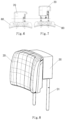
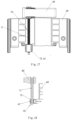
- the seat headrest device is in particular configured for a zero-gravity vehicle seat, and may have the following basic principle: as shown in figures 1 to 7 , a headrest 20 can be driven to move up and down relative to a seat backrest 80 (not shown in figures 1 and 2 ) by means of a pinion-rack mechanism 10 comprising a fixed rack 11, a pinion 12 and a movable rack 13 in engagement. A stroke L of the up-down movement of the headrest 20 is achieved by means of a screw-nut mechanism 70 only.
- the headrest 20 can be driven to move up and down relative to a fixed base 30 by means of a composite motion mechanism comprising the screw-nut mechanism 70 and the pinion-rack mechanism 10, wherein a stroke of the up-down movement of the headrest 20 can be doubled to 2L.
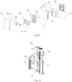
- FIG. 8 and FIG. 9 show a specific embodiment of the present application (It's noted, the specific embodiment as described below is merely an exemplary illustration of the seat headrest device of the present application, and doesn't restrict the protection scope defined by the claims).
- the seat headrest device may be in particular configured for a zero-gravity vehicle seat, but it may also be generally applicable to a wide variety of vehicle seats.
- the zero-gravity seat headrest device may comprise the fixed base 30, the headrest 20, a headrest electric motor 40, a slider base 50, a slider 60, the screw-nut mechanism 70 and the pinion-rack mechanism 10.
- the base 50 is configured as a base for the slider 60, and thus may be referred to as a "slider base”.
- the slider may be generally understood as a slidable part, which may have a planar, block, or any other suitable geometry.
- the base 50 may be arranged in the headrest 20, as a base for many components, and thus may be generally referred to as an "internal base”.
- the fixed base 30 is mounted to a seat backrest 80 through a headrest support rod 31.
- a specific mounting process is known in the prior art, and thus isn't described in detail again.
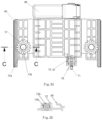
- the headrest 20 comprises a headrest front cover 21 and a headrest rear cover 22, which are fixed together through a fastener such as screws 23 to form the headrest 20.
- the headrest electric motor 40, the slider base 50, the slider 60, the screw-nut mechanism 70 and the pinion-rack mechanism 10 are all arranged in the headrest 20, wherein the stroke of the headrest satisfies the requirements, and both the headrest 20 and the seat backrest 80 have a good appearance.
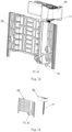
- the headrest 20 is movably supported on the slider base 50 through the pinion-rack mechanism 10, the slider 60 and the screw-nut mechanism 70, and the headrest 20 is driven to move up and down relative to the slider base 50 through the composite motion mechanism comprising the screw-nut mechanism 70 and the pinion-rack mechanism 10, so that the stroke of the headrest 20 is doubled in comparison with the stroke in the case of the known screw-nut mechanism.
- the slider base 50 is arranged in the headrest 20, and penetrates through the headrest rear cover 22 and is fixed to the fixed base 30, wherein the headrest rear cover 22 moves up and down relative to the slider base 50.
- a lower part of the slider base 50 is fixed to the fixed base 30.
- the headrest electric motor 40 is mounted to a motor mounting plate 42 through motor fixing screw bolts 41, and the motor mounting plate 42 is mounted to the slider base 50 through screws 43.
- the screw-nut mechanism 70 is a set, wherein an upper end of a lead screw 71 penetrates through a lead screw hole 42a in the motor mounting plate 42 and is connected with an output shaft of the headrest electric motor 40, and a lower end of the lead screw 71 is arranged in the slider base 50 through a shaft.
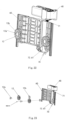
- Two sets of pinion-rack mechanisms 10 are provided, wherein the two sets of pinion-rack mechanisms 10 are symmetrically mounted to the left side and the right side of the slider base 50 parallel to an axial direction of the lead screw 71 (it's noted that the two sets of pinion-rack mechanisms 10 are not limited to a symmetrical arrangement).
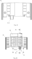
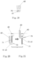
- a nut 72 of the screw-nut mechanism 70 is mounted to a nut receptacle 61 of the slider 60, wherein the nut 72 engages with the lead screw 71, wherein the headrest electric motor 40 drives the slider 60 to move up and down by means of the screw-nut mechanism 70 (in particular see figures 20 and 21 ).
- the slider base 50 is provided with a guide groove 51 for the nut receptacle, and the nut receptacle 61 moves up and down in the guide seat 51 for the nut receptacle.
- the two pinions 12 of the two sets of pinion-rack mechanisms 10 are mounted to the left side and the right side of the slider 60 parallel to its movement direction by means of respective countersink screws 12a and bushings 12b sleeved on the countersink screws 12a, wherein each pinion 12 engages with the fixed rack 11 of the same set of pinion-rack mechanism 10, and is rotatable around an axis of the countersink screw 12a.
- the headrest electric motor 40 drives the slider 60 to move up and down through the screw-nut mechanism 70, the pinions 12 move up and down along with the slider 60, and rotate at the same time under their engagement with the fixed racks 11.
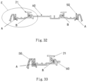
- the movable racks 13 in the two sets of pinion-rack mechanisms 10 are symmetrically mounted to the left side and the right side of the headrest front cover 21 parallel to a movement direction of the headrest 20 (it's noted, the present invention isn't limited to a symmetrical arrangement).
- the two movable racks 12 engage with the respective pinions 12.
- the pinions 12 are driven to move up and down.
- the pinions 12 engage with the fixed racks 11, the pinions 12 rotate about their own axis, the self-rotating pinions 12 engage with the movable racks 13, and the movable racks 13 drive the headrest front cover 21, and hence drives the headrest 20 to move up and down, wherein the stroke of the headrest 20 is increased.
- the slider 60 and the slider base 50 are coupled in a slidable manner through a pair of first sliding rail structures A; and the headrest 20, in detail the headrest front cover 21, and the slider 60 are coupled in a slidable manner through second sliding rail structures B, so that the stability of the movement of the headrest 20 is ensured.
- the headrest adjusting mechanism comprising the screw-nut mechanism 70 and the pinion-rack mechanism 10 can meet various requirements of a zero-gravity seat.
Landscapes
- Engineering & Computer Science (AREA)
- Aviation & Aerospace Engineering (AREA)
- Transportation (AREA)
- Mechanical Engineering (AREA)
- Chair Legs, Seat Parts, And Backrests (AREA)
- Seats For Vehicles (AREA)
Applications Claiming Priority (2)
| Application Number | Priority Date | Filing Date | Title |
|---|---|---|---|
| CN202121661847.6U CN216915626U (zh) | 2021-07-21 | 2021-07-21 | 一种零重力座椅头枕 |
| PCT/CN2022/079677 WO2023000682A1 (zh) | 2021-07-21 | 2022-03-08 | 座椅头枕和车辆座椅 |
Publications (2)
| Publication Number | Publication Date |
|---|---|
| EP4375138A1 true EP4375138A1 (de) | 2024-05-29 |
| EP4375138A4 EP4375138A4 (de) | 2025-08-06 |
Family
ID=82222218
Family Applications (1)
| Application Number | Title | Priority Date | Filing Date |
|---|---|---|---|
| EP22844855.1A Pending EP4375138A4 (de) | 2021-07-21 | 2022-03-08 | Sitzkopfstütze und fahrzeugsitz |
Country Status (4)
| Country | Link |
|---|---|
| US (1) | US20240140287A1 (de) |
| EP (1) | EP4375138A4 (de) |
| CN (1) | CN216915626U (de) |
| WO (1) | WO2023000682A1 (de) |
Cited By (1)
| Publication number | Priority date | Publication date | Assignee | Title |
|---|---|---|---|---|
| EP4464552A4 (de) * | 2022-01-10 | 2026-01-14 | Yanfeng International Automotive Tech Co Ltd | Kopfstützenstruktur |
Families Citing this family (2)
| Publication number | Priority date | Publication date | Assignee | Title |
|---|---|---|---|---|
| KR20240039391A (ko) * | 2022-09-19 | 2024-03-26 | 현대자동차주식회사 | 차량용 헤드레스트 장치 |
| WO2026011146A1 (en) * | 2024-07-03 | 2026-01-08 | Yanfeng International Automotive Technology Co. Ltd. | Component for vehicle interior |
Family Cites Families (9)
| Publication number | Priority date | Publication date | Assignee | Title |
|---|---|---|---|---|
| DE10014989A1 (de) * | 2000-03-25 | 2001-09-27 | Bayerische Motoren Werke Ag | Fahrzeugsitz mit mindestens einer Verstelleinrichtung |
| KR20060100333A (ko) * | 2006-08-29 | 2006-09-20 | 최은혁 | 자동차용 자동 슬라이드형 헤드레스트 |
| CN102795133A (zh) * | 2012-07-21 | 2012-11-28 | 长春富维-江森自控汽车饰件系统有限公司 | 用于前后与侧翼角度调节的汽车座椅头枕调节机构 |
| CN108688540A (zh) | 2017-02-16 | 2018-10-23 | 现代企业 | 电动头枕装置 |
| CN106828232A (zh) * | 2017-03-17 | 2017-06-13 | 盐城市高跃机械有限公司 | 汽车座椅结构 |
| CN208344015U (zh) | 2018-04-13 | 2019-01-08 | 宁波继峰汽车零部件股份有限公司 | 一种电动头枕 |
| CN209112003U (zh) * | 2018-11-29 | 2019-07-16 | 吉林省中凯宝创汽车技术有限公司 | 一种汽车用可调节头枕 |
| CN212047040U (zh) | 2020-03-31 | 2020-12-01 | 沈阳金杯安道拓汽车部件有限公司 | 新型可简易装拆的汽车电动升降头枕驱动模块 |
| CN213676465U (zh) * | 2020-09-18 | 2021-07-13 | 扬州伍德机械科技有限公司 | 一种汽车座椅靠背用头部支撑结构 |
-
2021
- 2021-07-21 CN CN202121661847.6U patent/CN216915626U/zh active Active
-
2022
- 2022-03-08 EP EP22844855.1A patent/EP4375138A4/de active Pending
- 2022-03-08 US US18/565,839 patent/US20240140287A1/en active Pending
- 2022-03-08 WO PCT/CN2022/079677 patent/WO2023000682A1/zh not_active Ceased
Cited By (1)
| Publication number | Priority date | Publication date | Assignee | Title |
|---|---|---|---|---|
| EP4464552A4 (de) * | 2022-01-10 | 2026-01-14 | Yanfeng International Automotive Tech Co Ltd | Kopfstützenstruktur |
Also Published As
| Publication number | Publication date |
|---|---|
| CN216915626U (zh) | 2022-07-08 |
| US20240140287A1 (en) | 2024-05-02 |
| WO2023000682A1 (zh) | 2023-01-26 |
| EP4375138A4 (de) | 2025-08-06 |
Similar Documents
| Publication | Publication Date | Title |
|---|---|---|
| EP4375138A1 (de) | Sitzkopfstütze und fahrzeugsitz | |
| RU146782U1 (ru) | Система наклона верхней части спинки кресла | |
| AU2002250109B2 (en) | Universal ergonomic support with self-contained actuator | |
| US6908152B2 (en) | Push lumbar support with flexible pressure surface | |
| AU2002250109A1 (en) | Universal ergonomic support with self-contained actuator | |
| US10899260B2 (en) | Headrest of a vehicle seat | |
| US20110278891A1 (en) | Modular contour support apparatus | |
| US5709363A (en) | Structure of powered seat | |
| KR101388983B1 (ko) | 승하강이 용이한 자동차용 럼버서포트 | |
| KR101725413B1 (ko) | 차량용 시트 사이드 볼스터 장치 | |
| CN112297973A (zh) | 一种防震效果好的汽车座椅 | |
| CN221137795U (zh) | 座椅头枕 | |
| CN109677307A (zh) | 可调脚踏装置及交通工具 | |
| KR20120090685A (ko) | 럼버서포트 어셈블리 | |
| CN220410364U (zh) | 一种便于根据不同人体特征调节的零重力座椅 | |
| CN112498203A (zh) | 机械按摩腰托 | |
| CN216424166U (zh) | 一种汽车座椅用超薄头枕 | |
| CN212465473U (zh) | 可调节式沙发靠背支架 | |
| CN213281959U (zh) | 一种桌面角度调节装置及桌具 | |
| CN209616967U (zh) | 可调脚踏装置及交通工具 | |
| CN220130000U (zh) | 一种汽车座椅头枕结构 | |
| KR102683795B1 (ko) | 모빌리티용 헤드레스트 장치 | |
| CN221213605U (zh) | 变形座椅及运载设备 | |
| CN214631152U (zh) | 一种按摩伸缩装置及坐具 | |
| CN218949337U (zh) | 车辆驾驶室 |
Legal Events
| Date | Code | Title | Description |
|---|---|---|---|
| STAA | Information on the status of an ep patent application or granted ep patent |
Free format text: STATUS: THE INTERNATIONAL PUBLICATION HAS BEEN MADE |
|
| PUAI | Public reference made under article 153(3) epc to a published international application that has entered the european phase |
Free format text: ORIGINAL CODE: 0009012 |
|
| STAA | Information on the status of an ep patent application or granted ep patent |
Free format text: STATUS: REQUEST FOR EXAMINATION WAS MADE |
|
| 17P | Request for examination filed |
Effective date: 20240214 |
|
| AK | Designated contracting states |
Kind code of ref document: A1 Designated state(s): AL AT BE BG CH CY CZ DE DK EE ES FI FR GB GR HR HU IE IS IT LI LT LU LV MC MK MT NL NO PL PT RO RS SE SI SK SM TR |
|
| DAV | Request for validation of the european patent (deleted) | ||
| DAX | Request for extension of the european patent (deleted) | ||
| REG | Reference to a national code |
Ref country code: DE Ref legal event code: R079 Free format text: PREVIOUS MAIN CLASS: B60N0002806000 Ipc: B60N0002821000 |
|
| A4 | Supplementary search report drawn up and despatched |
Effective date: 20250707 |
|
| RIC1 | Information provided on ipc code assigned before grant |
Ipc: B60N 2/821 20180101AFI20250701BHEP Ipc: B60N 2/829 20180101ALI20250701BHEP Ipc: B60N 2/02 20060101ALI20250701BHEP |
|
| GRAP | Despatch of communication of intention to grant a patent |
Free format text: ORIGINAL CODE: EPIDOSNIGR1 |
|
| STAA | Information on the status of an ep patent application or granted ep patent |
Free format text: STATUS: GRANT OF PATENT IS INTENDED |
|
| INTG | Intention to grant announced |
Effective date: 20251205 |