EP4373778B1 - Arbeitsmaschine mit batterieelemente - Google Patents
Arbeitsmaschine mit batterieelemente Download PDFInfo
- Publication number
- EP4373778B1 EP4373778B1 EP22740928.1A EP22740928A EP4373778B1 EP 4373778 B1 EP4373778 B1 EP 4373778B1 EP 22740928 A EP22740928 A EP 22740928A EP 4373778 B1 EP4373778 B1 EP 4373778B1
- Authority
- EP
- European Patent Office
- Prior art keywords
- site vehicle
- housing
- electric motor
- batteries
- chassis
- Prior art date
- Legal status (The legal status is an assumption and is not a legal conclusion. Google has not performed a legal analysis and makes no representation as to the accuracy of the status listed.)
- Active
Links
Images












Classifications
-
- B—PERFORMING OPERATIONS; TRANSPORTING
- B66—HOISTING; LIFTING; HAULING
- B66F—HOISTING, LIFTING, HAULING OR PUSHING, NOT OTHERWISE PROVIDED FOR, e.g. DEVICES WHICH APPLY A LIFTING OR PUSHING FORCE DIRECTLY TO THE SURFACE OF A LOAD
- B66F9/00—Devices for lifting or lowering bulky or heavy goods for loading or unloading purposes
- B66F9/06—Devices for lifting or lowering bulky or heavy goods for loading or unloading purposes movable, with their loads, on wheels or the like, e.g. fork-lift trucks
- B66F9/065—Devices for lifting or lowering bulky or heavy goods for loading or unloading purposes movable, with their loads, on wheels or the like, e.g. fork-lift trucks non-masted
-
- B—PERFORMING OPERATIONS; TRANSPORTING
- B60—VEHICLES IN GENERAL
- B60K—ARRANGEMENT OR MOUNTING OF PROPULSION UNITS OR OF TRANSMISSIONS IN VEHICLES; ARRANGEMENT OR MOUNTING OF PLURAL DIVERSE PRIME-MOVERS IN VEHICLES; AUXILIARY DRIVES FOR VEHICLES; INSTRUMENTATION OR DASHBOARDS FOR VEHICLES; ARRANGEMENTS IN CONNECTION WITH COOLING, AIR INTAKE, GAS EXHAUST OR FUEL SUPPLY OF PROPULSION UNITS IN VEHICLES
- B60K1/00—Arrangement or mounting of electrical propulsion units
-
- B—PERFORMING OPERATIONS; TRANSPORTING
- B60—VEHICLES IN GENERAL
- B60K—ARRANGEMENT OR MOUNTING OF PROPULSION UNITS OR OF TRANSMISSIONS IN VEHICLES; ARRANGEMENT OR MOUNTING OF PLURAL DIVERSE PRIME-MOVERS IN VEHICLES; AUXILIARY DRIVES FOR VEHICLES; INSTRUMENTATION OR DASHBOARDS FOR VEHICLES; ARRANGEMENTS IN CONNECTION WITH COOLING, AIR INTAKE, GAS EXHAUST OR FUEL SUPPLY OF PROPULSION UNITS IN VEHICLES
- B60K17/00—Arrangement or mounting of transmissions in vehicles
- B60K17/34—Arrangement or mounting of transmissions in vehicles for driving both front and rear wheels, e.g. four wheel drive vehicles
- B60K17/344—Arrangement or mounting of transmissions in vehicles for driving both front and rear wheels, e.g. four wheel drive vehicles having a transfer gear
-
- B—PERFORMING OPERATIONS; TRANSPORTING
- B60—VEHICLES IN GENERAL
- B60K—ARRANGEMENT OR MOUNTING OF PROPULSION UNITS OR OF TRANSMISSIONS IN VEHICLES; ARRANGEMENT OR MOUNTING OF PLURAL DIVERSE PRIME-MOVERS IN VEHICLES; AUXILIARY DRIVES FOR VEHICLES; INSTRUMENTATION OR DASHBOARDS FOR VEHICLES; ARRANGEMENTS IN CONNECTION WITH COOLING, AIR INTAKE, GAS EXHAUST OR FUEL SUPPLY OF PROPULSION UNITS IN VEHICLES
- B60K17/00—Arrangement or mounting of transmissions in vehicles
- B60K17/34—Arrangement or mounting of transmissions in vehicles for driving both front and rear wheels, e.g. four wheel drive vehicles
- B60K17/356—Arrangement or mounting of transmissions in vehicles for driving both front and rear wheels, e.g. four wheel drive vehicles having fluid or electric motor, for driving one or more wheels
-
- B—PERFORMING OPERATIONS; TRANSPORTING
- B66—HOISTING; LIFTING; HAULING
- B66F—HOISTING, LIFTING, HAULING OR PUSHING, NOT OTHERWISE PROVIDED FOR, e.g. DEVICES WHICH APPLY A LIFTING OR PUSHING FORCE DIRECTLY TO THE SURFACE OF A LOAD
- B66F9/00—Devices for lifting or lowering bulky or heavy goods for loading or unloading purposes
- B66F9/06—Devices for lifting or lowering bulky or heavy goods for loading or unloading purposes movable, with their loads, on wheels or the like, e.g. fork-lift trucks
- B66F9/065—Devices for lifting or lowering bulky or heavy goods for loading or unloading purposes movable, with their loads, on wheels or the like, e.g. fork-lift trucks non-masted
- B66F9/0655—Devices for lifting or lowering bulky or heavy goods for loading or unloading purposes movable, with their loads, on wheels or the like, e.g. fork-lift trucks non-masted with a telescopic boom
-
- B—PERFORMING OPERATIONS; TRANSPORTING
- B66—HOISTING; LIFTING; HAULING
- B66F—HOISTING, LIFTING, HAULING OR PUSHING, NOT OTHERWISE PROVIDED FOR, e.g. DEVICES WHICH APPLY A LIFTING OR PUSHING FORCE DIRECTLY TO THE SURFACE OF A LOAD
- B66F9/00—Devices for lifting or lowering bulky or heavy goods for loading or unloading purposes
- B66F9/06—Devices for lifting or lowering bulky or heavy goods for loading or unloading purposes movable, with their loads, on wheels or the like, e.g. fork-lift trucks
- B66F9/075—Constructional features or details
- B66F9/07513—Details concerning the chassis
- B66F9/07531—Battery compartments
-
- B—PERFORMING OPERATIONS; TRANSPORTING
- B66—HOISTING; LIFTING; HAULING
- B66F—HOISTING, LIFTING, HAULING OR PUSHING, NOT OTHERWISE PROVIDED FOR, e.g. DEVICES WHICH APPLY A LIFTING OR PUSHING FORCE DIRECTLY TO THE SURFACE OF A LOAD
- B66F9/00—Devices for lifting or lowering bulky or heavy goods for loading or unloading purposes
- B66F9/06—Devices for lifting or lowering bulky or heavy goods for loading or unloading purposes movable, with their loads, on wheels or the like, e.g. fork-lift trucks
- B66F9/075—Constructional features or details
- B66F9/07513—Details concerning the chassis
- B66F9/0754—Battery removal arrangements
-
- H—ELECTRICITY
- H01—ELECTRIC ELEMENTS
- H01M—PROCESSES OR MEANS, e.g. BATTERIES, FOR THE DIRECT CONVERSION OF CHEMICAL ENERGY INTO ELECTRICAL ENERGY
- H01M10/00—Secondary cells; Manufacture thereof
- H01M10/05—Accumulators with non-aqueous electrolyte
- H01M10/052—Li-accumulators
- H01M10/0525—Rocking-chair batteries, i.e. batteries with lithium insertion or intercalation in both electrodes; Lithium-ion batteries
-
- H—ELECTRICITY
- H01—ELECTRIC ELEMENTS
- H01M—PROCESSES OR MEANS, e.g. BATTERIES, FOR THE DIRECT CONVERSION OF CHEMICAL ENERGY INTO ELECTRICAL ENERGY
- H01M50/00—Constructional details or processes of manufacture of the non-active parts of electrochemical cells other than fuel cells, e.g. hybrid cells
- H01M50/20—Mountings; Secondary casings or frames; Racks, modules or packs; Suspension devices; Shock absorbers; Transport or carrying devices; Holders
- H01M50/244—Secondary casings; Racks; Suspension devices; Carrying devices; Holders characterised by their mounting method
-
- H—ELECTRICITY
- H01—ELECTRIC ELEMENTS
- H01M—PROCESSES OR MEANS, e.g. BATTERIES, FOR THE DIRECT CONVERSION OF CHEMICAL ENERGY INTO ELECTRICAL ENERGY
- H01M50/00—Constructional details or processes of manufacture of the non-active parts of electrochemical cells other than fuel cells, e.g. hybrid cells
- H01M50/20—Mountings; Secondary casings or frames; Racks, modules or packs; Suspension devices; Shock absorbers; Transport or carrying devices; Holders
- H01M50/249—Mountings; Secondary casings or frames; Racks, modules or packs; Suspension devices; Shock absorbers; Transport or carrying devices; Holders specially adapted for aircraft or vehicles, e.g. cars or trains
-
- B—PERFORMING OPERATIONS; TRANSPORTING
- B60—VEHICLES IN GENERAL
- B60K—ARRANGEMENT OR MOUNTING OF PROPULSION UNITS OR OF TRANSMISSIONS IN VEHICLES; ARRANGEMENT OR MOUNTING OF PLURAL DIVERSE PRIME-MOVERS IN VEHICLES; AUXILIARY DRIVES FOR VEHICLES; INSTRUMENTATION OR DASHBOARDS FOR VEHICLES; ARRANGEMENTS IN CONNECTION WITH COOLING, AIR INTAKE, GAS EXHAUST OR FUEL SUPPLY OF PROPULSION UNITS IN VEHICLES
- B60K17/00—Arrangement or mounting of transmissions in vehicles
- B60K17/22—Arrangement or mounting of transmissions in vehicles characterised by arrangement, location, or type of main drive shafting, e.g. cardan shaft
-
- B—PERFORMING OPERATIONS; TRANSPORTING
- B60—VEHICLES IN GENERAL
- B60K—ARRANGEMENT OR MOUNTING OF PROPULSION UNITS OR OF TRANSMISSIONS IN VEHICLES; ARRANGEMENT OR MOUNTING OF PLURAL DIVERSE PRIME-MOVERS IN VEHICLES; AUXILIARY DRIVES FOR VEHICLES; INSTRUMENTATION OR DASHBOARDS FOR VEHICLES; ARRANGEMENTS IN CONNECTION WITH COOLING, AIR INTAKE, GAS EXHAUST OR FUEL SUPPLY OF PROPULSION UNITS IN VEHICLES
- B60K1/00—Arrangement or mounting of electrical propulsion units
- B60K1/04—Arrangement or mounting of electrical propulsion units of the electric storage means for propulsion
- B60K2001/0405—Arrangement or mounting of electrical propulsion units of the electric storage means for propulsion characterised by their position
-
- B—PERFORMING OPERATIONS; TRANSPORTING
- B60—VEHICLES IN GENERAL
- B60K—ARRANGEMENT OR MOUNTING OF PROPULSION UNITS OR OF TRANSMISSIONS IN VEHICLES; ARRANGEMENT OR MOUNTING OF PLURAL DIVERSE PRIME-MOVERS IN VEHICLES; AUXILIARY DRIVES FOR VEHICLES; INSTRUMENTATION OR DASHBOARDS FOR VEHICLES; ARRANGEMENTS IN CONNECTION WITH COOLING, AIR INTAKE, GAS EXHAUST OR FUEL SUPPLY OF PROPULSION UNITS IN VEHICLES
- B60K1/00—Arrangement or mounting of electrical propulsion units
- B60K1/04—Arrangement or mounting of electrical propulsion units of the electric storage means for propulsion
- B60K2001/0455—Removal or replacement of the energy storages
- B60K2001/0477—Removal or replacement of the energy storages from the back
-
- B—PERFORMING OPERATIONS; TRANSPORTING
- B60—VEHICLES IN GENERAL
- B60K—ARRANGEMENT OR MOUNTING OF PROPULSION UNITS OR OF TRANSMISSIONS IN VEHICLES; ARRANGEMENT OR MOUNTING OF PLURAL DIVERSE PRIME-MOVERS IN VEHICLES; AUXILIARY DRIVES FOR VEHICLES; INSTRUMENTATION OR DASHBOARDS FOR VEHICLES; ARRANGEMENTS IN CONNECTION WITH COOLING, AIR INTAKE, GAS EXHAUST OR FUEL SUPPLY OF PROPULSION UNITS IN VEHICLES
- B60K1/00—Arrangement or mounting of electrical propulsion units
- B60K1/04—Arrangement or mounting of electrical propulsion units of the electric storage means for propulsion
- B60K2001/0455—Removal or replacement of the energy storages
- B60K2001/0483—Removal or replacement of the energy storages from the front
-
- B—PERFORMING OPERATIONS; TRANSPORTING
- B60—VEHICLES IN GENERAL
- B60K—ARRANGEMENT OR MOUNTING OF PROPULSION UNITS OR OF TRANSMISSIONS IN VEHICLES; ARRANGEMENT OR MOUNTING OF PLURAL DIVERSE PRIME-MOVERS IN VEHICLES; AUXILIARY DRIVES FOR VEHICLES; INSTRUMENTATION OR DASHBOARDS FOR VEHICLES; ARRANGEMENTS IN CONNECTION WITH COOLING, AIR INTAKE, GAS EXHAUST OR FUEL SUPPLY OF PROPULSION UNITS IN VEHICLES
- B60K1/00—Arrangement or mounting of electrical propulsion units
- B60K1/04—Arrangement or mounting of electrical propulsion units of the electric storage means for propulsion
- B60K2001/0455—Removal or replacement of the energy storages
- B60K2001/0494—Removal or replacement of the energy storages with arrangements for sliding
-
- B—PERFORMING OPERATIONS; TRANSPORTING
- B60—VEHICLES IN GENERAL
- B60Y—INDEXING SCHEME RELATING TO ASPECTS CROSS-CUTTING VEHICLE TECHNOLOGY
- B60Y2410/00—Constructional features of vehicle sub-units
- B60Y2410/115—Electric wiring; Electric connectors
-
- H—ELECTRICITY
- H01—ELECTRIC ELEMENTS
- H01M—PROCESSES OR MEANS, e.g. BATTERIES, FOR THE DIRECT CONVERSION OF CHEMICAL ENERGY INTO ELECTRICAL ENERGY
- H01M2220/00—Batteries for particular applications
- H01M2220/20—Batteries in motive systems, e.g. vehicle, ship, plane
Definitions
- the invention relates to a work machine comprising a lifting arm and battery cells for providing electrical power to the work machine.
- a work machine comprising a mobile chassis movable on the ground surface, the chassis comprising two side members parallel to each other and extending parallel to a front-rear axis of the machine, and a lifting arm, the lifting arm being mounted between the two side members so as to be pivotally movable relative to the two side members.
- Certain aspects of the invention are based on the observation that in order for the autonomy of the electrically powered work machine not to be too low, it must carry a substantial volume of battery cells; and that it is therefore necessary to find a solution for positioning the battery cells in the work machine.
- the general balance of the machine depends on the distribution of the main masses, including the battery cells.
- the battery cells must be protected against impacts, in particular due to objects falling from a height. Indeed, in the event of an impact, the battery cells are likely to be damaged, which can render them non-functional or even lead to a risk of fire or explosion when the battery cells are lithium-ion battery cells.
- One idea behind the invention is to be able to position the battery elements between the two chassis side members.
- the battery cells Due to the fact that the battery cells are arranged between the two side members between which the lifting arm is articulated, the battery cells contribute to the lateral balancing of the work machine, or at least do not contribute significantly to a lateral imbalance of the work machine, since the center of mass of all the battery cells taken together is located relatively close to, or even exactly on a median longitudinal axis of the work machine. In addition, the battery cells are located under the lifting arm and well protected against impacts, and in particular more protected against impacts than if they were arranged on one side of the work machine.
- the expression “electrically connected” includes both a direct electrical connection (without any interposed electrical element) and an indirect electrical connection (with one or more interposed electrical elements).
- such a work machine may have one or more of the following characteristics.
- the battery elements are arranged on either side of a median longitudinal axis of the work machine and/or straddling the median longitudinal axis of the work machine, preferably with a mass distribution that is substantially balanced relative to the median longitudinal axis.
- the battery cells have a relatively neutral or even a favourable effect on the lateral balancing of the machine.
- an overall acceptable lateral balancing of the work machine can be achieved by a balanced arrangement of the other components of the work machine. This balanced arrangement can also be achieved in different ways.
- the work machine further comprises a front axle mounted at a front end portion of the chassis and a rear axle mounted at a rear end portion of the chassis, and at least one transmission coupling said at least one electric motor to at least one of the front axle and the rear axle.
- end portion here refers not only to an end of the chassis but also to an area near the end.
- the chassis may have an overhang portion in front of the front axle and/or behind the rear axle.
- the battery cells are arranged between the front axle and the rear axle along the longitudinal direction.
- Both the propulsion of the work machine and the actuation of the lifting arm can be partially or even fully electric.
- the machine can have one drive axle or two drive axles.
- the drive axle can be a front axle or a rear axle.
- the machine may use one or more electric motors coupled by a mechanical transmission chain to the axle, in other words an electromechanical drive.
- the mechanical transmission chain may comprise one or more elements selected from the group consisting of: a reduction gear train, a transmission shaft and a universal joint.
- the electric motor may be a motor dedicated to propulsion.
- the machine may use one or more electric motors coupled by a hydraulic transmission chain to the axle, in other words an electrohydraulic drive.
- the hydraulic transmission chain may comprise a hydraulic pump driven by the electric motor and at least one hydraulic motor driven by a hydraulic flow generated by the hydraulic pump.
- the hydraulic transmission chain may be a hydrostatic transmission chain, i.e. in a closed circuit.
- the hydraulic pump and the electric motor may be dedicated to propulsion.
- the hydraulic pump and the electric motor may be common with other hydraulic functions of the machine, such as a hydraulic actuation function of the lifting arm or other.
- the machine may use two independent drives or a common drive.
- the two independent drives may be of different types, for example an electromechanical drive and an electrohydraulic drive, or of identical types, for example two electromechanical drives.
- the common drive may comprise two drive shafts connecting the two axles to a common motor, which may be an electric motor or a hydraulic motor.
- the common motor may be a motor dedicated to propulsion.
- said at least one electric motor comprises: an electric propulsion motor for propelling the chassis, the battery elements being electrically connected to the electric propulsion motor via a first electric speed variator, said transmission comprising a chain of mechanical or hydraulic transmission coupling said electric propulsion motor to at least one of the front axle and the rear axle.
- said at least one electric motor comprises a first electric propulsion motor coupled to the front axle by a first mechanical transmission chain and a second electric propulsion motor coupled to the rear axle by a second mechanical transmission chain.
- said transmission comprises a hydraulic transmission chain coupling said at least one electric motor to at least one of the front axle and the rear axle, the hydraulic transmission chain comprising at least one hydraulic pump driven by said at least one electric motor and at least one hydraulic motor driven by a hydraulic flow generated by said hydraulic pump, said at least one hydraulic motor being coupled to at least one of the front axle and the rear axle.
- the machine may comprise one or more electric actuators, namely an electric actuation for example by an electric cylinder, and/or one or more hydraulic actuators powered by one or more pumps driven by one or more electric motors, namely an electrohydraulic actuation, for example by a hydraulic cylinder.
- electric actuators namely an electric actuation for example by an electric cylinder
- hydraulic actuators powered by one or more pumps driven by one or more electric motors, namely an electrohydraulic actuation, for example by a hydraulic cylinder.
- actuators of different types for example at least one electric actuator and at least one hydraulic actuator, or of identical types, for example several hydraulic actuators, may be provided to actuate different movements or degrees of freedom of the lifting arm.
- the different movements may be chosen from the group consisting of: a raising-lowering movement, an extension-retraction movement and a tilting movement of a tool holder.
- said at least one electric motor comprises an electric actuating motor for actuating the lifting arm, the battery elements being connected to the electric actuating motor via an electric speed variator.
- the at least one electric actuating motor comprises at least one electric cylinder configured to actuate at least one movement of the lifting arm.
- the work machine further comprises a hydraulic pump coupled to the electric actuating motor and at least one hydraulic actuator powered by the hydraulic pump to actuate at least one movement of the lifting arm.
- independent hydraulic pumps may be used or a hydraulic pump common can be used.
- Independent hydraulic pumps can be driven by several respective electric motors.
- the battery cells may be electrically connected to a single electric motor or to several electric motors to provide power to said electric motor(s) for propulsion of the chassis and for actuation of the lifting arm.
- the work machine further comprises a cabin for a driver of the work machine, the cabin being located projecting on a lateral side of the chassis of the work machine.
- the weight of the cab may be balanced in various ways, including independently of the weight of the battery cells that are located between the two side members of the work machine.
- the weight of the cab may be balanced by cells located in a protruding compartment on a second lateral side of the work machine frame, opposite the cab. These cells may include an electric drive motor, an electric drive motor, a hydraulic pump, a hydraulic fluid reservoir, and/or other cells.
- the electric motor(s) may be arranged at various locations in the work machine. According to one embodiment, an electric propulsion motor and/or an electric actuating motor is located between the two side members or under the two side members.
- the chassis comprises a housing receiving the battery elements, the housing having an opening opening towards a direction chosen from the front of the work machine, the rear of the work machine, the top of the chassis, the bottom of the chassis and a lateral direction opposite a cabin of the work machine.
- the housing has a lower surface on which the battery cells rest directly or indirectly.
- Directly resting means that the battery cells rest on the bottom surface without any part interposed between the battery cells and the bottom surface. Conversely, “indirectly resting” means that at least one part is interposed between the bottom surface and the battery cells.
- the lower surface is inclined toward the ground surface in a direction away from the opening.
- the opening of the housing is closed by a ventilation grille.
- the housing has a vent port spaced from the opening, which may be located at an end opposite the vent grille or at another location.
- a shaft of an electric propulsion motor extends under the housing.
- the work machine furthermore has additional battery cells for supplying electrical power to said at least one electric motor of the work machine, the additional battery cells being arranged between the two side members, and the chassis comprises an additional housing receiving the additional battery cells, the additional housing having an opening opening towards the rear of the work machine and a lower surface on which the additional battery cells rest directly or indirectly.
- Additional battery cells allow the autonomy and/or power of the work machine to be increased.
- the additional battery cells rest on a tray, the tray resting on the lower surface of the additional housing and having a rim that seals the opening of the additional housing when the additional battery cells are received in the additional housing.
- the lower surface of the additional housing is inclined toward the ground surface in a direction away from the opening of the additional housing.
- the rim is provided with at least one ventilation grille.
- the additional housing has a ventilation orifice at an end opposite the at least one ventilation grille of the rim.
- the battery cells may be provided in the form of a battery pack according to a second subject matter of the invention.
- Another idea behind the invention is to provide battery packs that can be easily inserted between the two side members.
- such a battery pack may have one or more of the following features.
- the greatest width l and the greatest height h verify the inequality h/l ⁇ 0.60.
- the greatest length L and the greatest width l verify the inequality l/L ⁇ 0.30.
- the support plate includes a plurality of polymer pads on a lower face opposite the upper face to which the battery cells are attached.
- the support plate has, at one of its ends in the length direction, two through holes, the through holes being sized to allow a human operator to lift the battery assembly by said end by grasping the support plate by the two through holes.
- the support plate carries a plurality of projecting elements in the width direction and/or in the length direction, the projecting elements being capable of cooperating with slinging elements.
- the battery cells are lithium-ion battery cells.
- the battery assembly further comprises at least one roller mounted freely rotatable on an upper surface of the battery assembly, the roller being intended to roll against a surface of the work machine during a movement of the battery assembly in the length direction.
- the support plate has a plurality of lights, the lights being aligned with each other in the length direction of the battery pack and arranged so as to be able to cooperate with a gear wheel when moving the support plate in the length direction.
- the battery assembly further comprises a projecting stud at a longitudinal end of the battery assembly, the projecting stud being intended to cooperate with a centering orifice located in the work machine.
- the invention also proposes a work machine according to any one of the embodiments described above, in which the battery assembly is according to any one of the embodiments which have just been described, and the battery assembly is arranged between the two side members.
- the housing receiving the battery assembly has an upper surface facing the lower surface, the upper surface having an inclined face such that a cross-section of the housing widens towards the opening.
- the battery assembly comprises the at least one freely rotatable roller mentioned above, and the roller is arranged to cooperate with the inclined face when the battery assembly is extracted from the housing through the opening of the housing.
- the battery assembly comprises the plurality of lights mentioned above
- the chassis comprises a shaft located in the vicinity of the opening of the housing, the shaft carrying a toothed wheel arranged so as to be able to cooperate with the lights of the support plate and thus move the support plate in translation when the shaft is driven in rotation.
- the battery assembly comprises the above-mentioned protruding stud, the protruding stud being received in a centering hole located at an end of the housing which is opposite the opening of the housing.
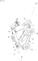
- FIG.1A is a perspective overall view of a work machine 1, here implemented in the form of a telescopic forklift.
- the work machine 1 comprises a chassis 2 and a lifting arm 20.
- the arrow AA represents a median front-rear axis of the work machine 1, aligned with the middle of the axles 3 and 4.
- the median front-rear axis corresponds to a longitudinal direction of the work machine 1.
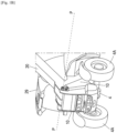
- the [ Fig.1B ] is a partial view of the rear of the same work machine 1.
- the chassis 2 is mobile and movable on the ground surface (not shown), here by means of a front axle 3 carrying two wheels 3A, one on the left and one on the right, and a rear axle 4 carrying two wheels 4A, one on the left and one on the right.
- the chassis 2 has two side members 10, which are better visible in particular on the figures 3 And 4 .
- the side members 10 are generally flat metal parts, parallel to each other and generally perpendicular to a width direction of the work machine. The largest dimension of the side members 10 extends parallel to the axis front-rear AA of working machine 1.
- the lifting arm 20 also extends in a plane perpendicular to the width direction of the work machine.
- the lifting arm 20 is articulated to the two side members 10, between the two side members 10, so as to be pivotally movable relative to the two side members 10 about a pivot axis P.
- the pivot axis P is in particular identified on the [ Fig.1A ].
- the pivot axis P is parallel to the width direction of the working machine 1. Suitable means for making the lifting arm 20 pivotally movable are well known as such and are not described in detail here.
- the lifting arm 20 can be implemented in various ways, including in the form of several telescopic sections as shown, or alternatively in the form of a fixed-length arm.
- One end of the lifting arm 20 opposite the pivot axis P can carry a work tool or, as shown in the [ Fig.1A ], a modular tool holder capable of receiving work tools of several types, according to known technology.
- work tool we mean for example a pair of forks, a bucket, a winch, a clamp, etc.
- the work machine 1 comprises a cabin 29 in which a driver of the work machine 1 can sit, and a box 28 capable of receiving various equipment used for operating the work machine 1.
- the cabin 29 and the box 28 are located here on either side of the side members 10, that is to say that the cabin 29 is located on a first lateral side of the work machine 1, and that the box 28 is located on a second lateral side of the work machine, the first lateral side and the second lateral side being on either side of the two side members 10.
- the pivot axis P is located behind the rear axle 4 along the front-rear axis AA. It is further located above the front axle 3 and the rear axle 4 along a vertical direction of the working machine 1.
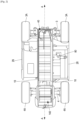
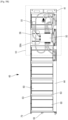
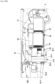
- Fig.2 is a view from below of the work machine 1.
- a set of batteries generally designated by the reference 40, is arranged between the two side members 10.
- the set of batteries 40 is connected to at least one electric motor of the work machine 1, in order to supply electricity to this at least one electric motor.
- an electric motor 80 for the propulsion of the chassis 2. The power transmission between the battery pack 40, the electric motor 80 and the axles 3 and 4 is described in detail below.
- an additional set of batteries is also arranged between the two side members 10.
- This additional set of batteries 140 is also connected to said at least one electric motor of the work machine 1, in order to supply electricity to this at least one motor. electric.
- the additional battery pack 140 increases the autonomy of the work machine 1.
- the battery pack 40 and if applicable the additional battery pack 140, are produced by combining several battery cells together, so as to achieve a terminal voltage sufficient to enable the operation of the work machine 1, without the work machine 1 having to carry another motorization such as an internal combustion engine.
- the battery cells can in principle be of any known type, for example of the lead-acid or lithium-ion type, and can be combined together and installed between the side members 10 in various ways.
- the space between the side members 10 may be somewhat difficult to access, depending on the dimensions of the work machine 1.
- the following is described in connection with the figures 3 has 17 various solutions allowing easy insertion and removal of the battery pack 40 and the additional battery pack 140 between the two side members 10.
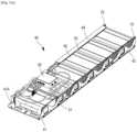
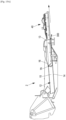
- FIG. 5A has 5D are views of a battery assembly 40 which is insertable between the two side members 10.
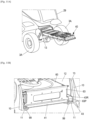
- the [ Fig.3 ] shows as an illustration this set of batteries 40 being inserted between the side members 10, here from the front of the work machine 1.
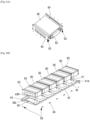
- the battery assembly 40 is generally parallelepipedal, and comprises a support plate 41 and several battery elements 60 fixed to an upper face 41A of the support plate 41.
- the support plate 41 is rigid and can be made of any material sufficiently strong to support the weight of the battery cells 60, for example steel.
- each battery element 60 comprises a parallelepiped housing 61 enclosing the electrolytic cell(s) generating the voltage at the terminals of the battery element 60.
- the battery element 60 is of the lithium-ion type.
- One of the faces of the housing 61 carries a battery management system (BMS) 62 which, in a manner known per se, monitors and manages the charging and discharging of all the electrolytic cells of the battery element 60.
- BMS battery management system
- This battery management system 62 also carries the output terminals of the battery element 60.
- two frame elements 63 are attached, here using screws 64, to two opposite faces of the housing 61.
- the support plate 41 can have, for each battery element 60, a ([ Fig.6B ]), two ([ Fig.13B ]), or more than two ventilation openings 42 passing through the support plate 41 so as to open onto one face of the housing 61. These ventilation openings 42 make it possible to limit the risk of accidental overheating of the battery elements 60.
- each battery element 60 delivers a voltage of 48V and a power of 4.2kW.
- the battery elements 60 are connected in series in pairs to provide a voltage of 96V each time.
- the pairs of battery elements 60 are connected in parallel with each other, i.e. three pairs in the case of six battery elements 60.
- one side of the support plate 41 may be provided with a raised edge 43 which helps to hold the battery cells 60 in position relative to the support plate 41.
- this raised edge 43 can be provided with through holes 43R, each through hole 43R receiving a projecting portion 63P of a frame element 63.
- the raised edge 43 can be produced in various ways, either in the form of a part added to the support plate 41, or in one piece with the support plate 41.
- a cable guide 44 may be installed on one side of the battery assembly 40 in order to hold in place and protect the electrical cables electrically connecting the battery elements 60 to the electrical connection box 50.
- This cable guide 44 may for example be attached to certain of the frame elements 63.
- the electrical connection box 50 can be fixed to a support plate 58 interposed between the electrical connection box 50 and the battery elements 60.
- the support plate 58 can be attached to some of the frame elements 63.
- the support plate 58 can have an air opening 58A making it possible to limit the risk of accidental overheating of the battery elements 60.
- the battery pack 40 further has a power output socket 51 allowing the electrical connection of the battery pack 40 to a power input socket 400 (not shown in the drawings).
- Figures 8A has 8D ) of the work machine 1.
- the power output socket 51 is intended to be electrically connected to an output of the electrical connection box 50.
- the battery pack 40 is ready to be inserted between the two side members 10 of the work machine 1.
- the battery pack 40 has a greater width l in a width direction of the battery pack 40, a greater length L in a length direction of the battery pack 40, and a greater height h in a height direction of the battery pack 40, the greater length L being greater than the greater width l.
- the greatest length L and the greatest height h satisfy the inequality h/L ⁇ 0.40. This means that h is relatively small compared to L, which gives the battery pack 40 a relatively flat and elongated shape, which allows the battery pack 40 to be positioned in a relatively long housing 12 and of a relatively low height, as will be described below.
- the largest width l and the largest height h can verify the inequality h/l ⁇ 0.60, and/or the largest length L and the largest width l can verify the inequality l/L ⁇ 0.30.
- the battery pack 40 is configured so as to be insertable between the two beams 10 of the work machine 1, in a state where the battery cells 60 are electrically connected to the electrical connection box 50 and the electrical connection box 50 is electrically connected to the power output socket 51.
- the battery assembly 40 may have a mass greater than 100 kg or even greater than 200 kg, which is too great to allow human operators to handle the battery assembly 40 without tools.
- the battery assembly 40 is received in a housing 12 provided in the chassis 2 between the side members 10.
- the side walls of the housing 12 are defined by side surfaces of the side members 10.
- the housing 12 further has a lower surface 14 and an upper surface 15 spaced from the lower surface 14.
- the support plate 41 on the lower surface 14 rests when the battery assembly 40 is in place in the housing 12.
- the largest dimension of the housing 12 is along the front-rear axis AA of the working machine 1. As can be seen in the figures, the battery pack 40 is inserted into the housing 12 so that its direction of greatest length is along the greatest dimension of the housing 12.
- the lower face 41B of the support plate 41 may be provided with a plurality of polymer pads, in order to reduce friction between the support plate 41 and the lower surface 14 of the housing 12 when inserting the battery pack 40 into the housing 12.
- the housing 12 has an opening 13 which is located at the front of the working machine 1 along the front-rear axis AA.
- each spar 10 is provided with a shoulder 11 in the vicinity of the opening 13. These shoulders 11 make it possible to fix one end of the support plate 41 to the spars 10 when the battery assembly 40 is in place in the housing 12. In the example shown in the [ Fig.11B ], this fixing of the support plate 41 to the shoulders 11 is carried out using bolts 99, but other types of fixing are possible.
- the support plate 41 may have two through holes 49.
- the through holes 49 are sized to allow a human operator to lift the battery assembly by said end by grasping the support plate by the two through holes 49.
- the through holes 49 may be of any suitable shape, for example elliptical, rectangular, or as shown in the drawings, in the shape of a rectangle completed by two semicircles at two opposite sides of the rectangle.
- the support plate 41 can be provided with a projecting stud 59, of cylindrical or more preferably truncated cone shape.
- the projecting stud 59 is here carried by a longitudinal rim 59L, which can be attached to the support plate 41 or formed in one piece with the support plate 41.
- the housing 12 has a centering piece 18 provided with a centering orifice (not referenced).
- the projecting stud 59 and the centering orifice are sized so that the projecting stud 59 is received in the centering orifice when the battery assembly 40 is in its intended location in the housing 12.
- the projecting stud 59 and the centering orifice tend to facilitate the installation of the battery assembly 40 in the housing 12.
- the lower surface 14 is inclined towards the ground in a direction away from the opening 13. This inclination towards the ground surface facilitates the insertion of the battery assembly 40 into the housing 12, and tends to prevent the battery assembly 40 from accidentally coming out of the housing 12 when the work machine 1 is in motion, including on inclined ground.
- the opening 13 may be closed by a ventilation grille. Furthermore, at the end of the housing 12 which is opposite the opening 13, the housing 12 may have a ventilation orifice (not shown in the drawings). By means of this ventilation grille and this ventilation orifice, air convection can occur through the housing 12 which tends to further reduce the risk of accidental overheating of the battery cells 60.
- the support plate 41 may have a plurality of lights 47 aligned with each other along the length direction of the battery assembly 40.
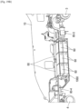
- the chassis 2 is provided with a toothed wheel 201 carried by a shaft 200, which are visible in the Figures 14A and 14B .
- the shaft 200 is mounted to rotate freely between two spaced plates 210 located in the vicinity of the opening 13 of the housing 12. Bearings 210 hold the toothed wheel 201 in position relative to the plates 210.
- the shaft 200 is provided with an imprint 209 which allows the shaft 200 to be driven in rotation by a tool 300.
- the tool 300 is here a crank actuated by a human operator, but any other type of tool may be suitable.
- the teeth 201A of the gear wheel 201 cooperate with the slots 47 of the support plate 41, in the manner of a pinion and a rack, which moves the support plate 41 and therefore the battery assembly 40 in translation. This allows an operator to begin extracting the battery assembly 40 from the housing 12 using the tool 300, after removing the bolts 99.
- the battery assembly 40 may further comprise two rollers 79 mounted free to rotate at its upper surface.
- the rollers 79 are here carried by the edge 43 of the support plate 41.
- the upper surface 15 of the housing 12 has a face 16 which is inclined so that a cross section of the housing 12 widens towards the opening 13.
- the Figures 15A And 15B together show that when the battery assembly 40 is extracted from the housing 12, the rollers 79 cooperate with the inclined face 16. This cooperation tends to facilitate the operation of extracting the battery assembly 40 from the housing 12. It is understood that the number and/or the dimensions and/or the positioning of the rollers 79 can be modified as long as this cooperation with the inclined face 16 is present.
- the support plate 41 can bear on its two longer sides a plurality of projecting elements 115. These projecting elements 115 are capable of cooperating with slinging elements.
- the operator can install slinging elements, which are here slinging eyes 120, on the protruding elements 115, and then install slings on the slinging elements, which allows lifting and moving the battery assembly 40.
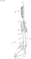
- an additional battery pack 140 may be arranged between the two side members 10. This additional battery pack 140 will now be described with reference to the Figures 8A has 8D And 16 and 17 .
- FIG. 8A has 8D show that the additional battery pack 140 has a generally parallelepiped shape, and comprises battery cells 60 and frame members 63 identical to those described above in connection with the battery pack 40.
- the additional battery pack 140 comprises two battery cells 60.
- the battery cells 60 are electrically connected to each other and to an additional power output socket 151 (not shown in the drawings).
- Figures 8A has 8D ) allowing the electrical connection of the additional battery assembly 140 to the electrical connection box 50 of the battery assembly 40.
- a cable guide 184 can be installed on one side of the additional battery assembly 140 in order to hold in place and protect the electrical cables making these electrical connections.
- the additional battery pack 140 may be provided with battery cells of a different construction and/or type than the battery cells 60.
- the additional battery pack 40 has a greater width l2 in a width direction than the additional battery pack 140, a greater length L2 in a length direction of the additional battery pack 140, and a greater height h2 in a height direction of the additional battery pack 140, the greater length L2 being greater than the greater width l2.
- the greatest length L2 and the greatest height h2 satisfy the inequality h2/L2 ⁇ 0.20.
- h2 is relatively small compared to L2, which gives the additional battery pack 140 a relatively flat and elongated shape, which allows the additional battery pack 140 to be positioned in a relatively long housing 112 and of a relatively low height, as will be described below.
- the largest width l2 and the largest height h2 can verify the inequality h2/l2 ⁇ 0.30, and/or the largest length L2 and the largest width l2 can verify the inequality l2/L2 ⁇ 0.70.
- the battery elements 60 of the additional battery pack 140 rest on a tray 170.
- the battery elements 60 are for example attached to the tray 170 by the frame elements 63.
- the tray 170 has a rim 180.
- the rim 180 has a handle 181 which allows an operator to handle the additional battery pack 140.
- the additional battery pack 140 is received in an additional housing 112 provided in the chassis 2 between the side members 10.
- the side walls of the additional housing 112 may be defined by side surfaces of the side members 10.
- the additional housing 112 further has a lower surface 113 on which the tray 170 rests when the additional battery pack 140 is received in the additional housing 112.
- the face of the tray 170 opposite that on which the battery cells 60 rest may be provided with a plurality of polymer pads, in order to reduce friction between the tray 170 and the lower surface 114 of the additional housing 112 when inserting the additional battery pack 140 into the additional housing 112.
- the additional housing 112 has an opening 113 which is located at the rear of the working machine 1 along the front-rear axis AA.
- the [ Fig.16 ] shows that the flange 180 closes the opening 113 when the additional battery pack 140 is received in the additional housing 112.
- the rim 180 is provided with several (here three) air vents 182. Furthermore, at the end of the additional housing 112 which is opposite the opening 113, the additional housing 112 may have an air vent (not shown in the drawings). Due to the air vents 182 and the air vent, air convection can occur through the additional housing 112 which tends to reduce the risk of accidental overheating of the battery cells 60.
- the plate 170 may be provided with a projecting stud 159, of cylindrical or more preferably truncated cone shape.
- the projecting stud 159 is here carried by a longitudinal rim 159L, which may be attached to the plate 170 or formed in one piece with the plate 170.
- the additional housing 112 has a part of centering 118 provided with a centering orifice (not referenced).
- the protruding stud 159 and the centering orifice are sized so that the protruding stud 159 is received in the centering orifice when the additional battery assembly 140 is in its intended location in the housing 112.
- the protruding stud 159 and the centering orifice tend to facilitate the installation of the additional battery assembly 140 in the housing 112.
- the lower surface 114 is inclined towards the ground in a direction away from the opening 113. This inclination towards the ground surface facilitates the insertion of the additional battery pack 140 into the additional housing 112, and tends to prevent the additional battery pack 140 from accidentally coming out of the additional housing 112 when the work machine 1 is in motion, including on inclined ground.
- the tray 170 may carry on its two longest sides a plurality of projecting elements 215. These projecting elements 215 are similar to the projecting elements 115 and capable of cooperating with slinging elements.
- the operator can install slinging elements, which are here slinging eyes 120, on the protruding elements 215, and then install slings on the slinging elements, which allows lifting and moving the additional battery pack 140.
- Fig.10 is a functional diagram showing the power supply of the work machine 1 using the battery pack 40 and the additional battery pack 140.
- the battery cells 60 are connected in series in pairs to provide a voltage of 96 V each time.
- the pairs of battery cells 60 are connected in parallel with each other, i.e. three pairs in the battery pack 40 and one pair in the additional battery pack 140.
- the additional battery pack 140 is electrically connected to the electrical connection box 50 via the additional power output socket 151.
- the battery pack 40 and the additional battery pack 140 are electrically connected, via the power output socket 51 of the battery pack 140, to a power input socket 400 of the work machine 1.
- the additional battery pack 140 contributes to the autonomy of the work machine 1.
- the work machine 1 comprises a power distribution box 410 which carries the power input socket 400 and which is configured to supply or not the electrical components of the work machine 1.
- power distribution boxes are known as such and are not described in detail here.
- the power distribution box 410 is in particular electrically connected to an 80V electric speed variator itself electrically connected to the electric motor 80, and to an 89V electric speed variator itself electrically connected to an electric motor 89 for actuating the lifting arm 20.
- the 80V and 89V electric speed variators are here of the three-phase inverter type, that is to say receiving a direct voltage as input and providing a three-phase alternating voltage as output. Other electrical configurations are however possible.
- the power distribution box 410 can further be electrically connected to other electrical equipment of the work machine 1, in particular a cabin heating module 29, and/or a cabin air conditioning module 29, and/or one or more direct-direct (DC/DC) converters for the electrical supply of other electrical equipment of the machine, for example a signal light, an audible warning device, etc.
- DC/DC direct-direct
- the power distribution box 410 can for example be received in the box 28.
- the electrical connection box 50 is arranged between the side members 10 due to its positioning on the battery assembly 40.
- the electrical connection box 50 can further be electrically connected to at least one charging socket for recharging the battery elements 60 of the battery set 40 and, where appropriate, of the battery set 140.
- the number of battery cells 60 on the [ Fig.10 ] is purely indicative. A greater or lesser number of battery cells 60 may be provided, depending on the electrical power requirements of the work machine 1. Furthermore, it is possible to provide not one but several electrical connection boxes 50, each electrically connected to one or more pairs of battery cells 60 connected in series in pairs to each time provide a voltage of 96 V. In this case, the electrical connection boxes 50 are electrically connected in parallel to the power distribution box 410.
- connection box 50 and the power distribution box 410 are co-located, and for example integrated in the form of a single connection and distribution box.
- the electric motor 80 provides propulsion for the chassis 2.
- the [ Fig.9 ] a transmission 81 providing power transmission between the electric motor 80 and the axles 3 and 4 of the chassis.
- An output shaft (not shown) of the electric motor 80 drives, via a reducer 82, two shafts 83 and 84.
- the shaft 84 drives a shaft input shaft 4B for driving the rear wheels 4A mounted on the rear axle 4, and the shaft 83 drives an input shaft 3B for driving the front wheels 3A mounted on the front axle 3.
- the shafts 83 and 84 here extend substantially parallel to the front-rear axis AA of the work machine 1 and therefore to the side members 10.
- the output shaft (not shown) of the electric motor 80 extends under the housing 12 formed between the side members 10. Alternatively, a large number of other configurations are possible for the transmission 81.
- the electric motor 89 ensures the actuation of the lifting arm 20.
- the electric motor 89 drives a hydraulic pump, which supplies hydraulic actuators, for example hydraulic cylinders, to actuate the movements of the lifting arm 20.
- the movements include for example the raising-lowering movements carried out by a lifting cylinder located under the lifting arm 20, the extension-retraction movements carried out by a telescoping cylinder located in the lifting arm 20, and the movements of the tool holder.
- Such hydraulic actuation of the lifting arm 20 is well known as such and is therefore not described in detail here.
- the electric motor 80 can be received in the box 28, as shown schematically in the sectional view from below of the [ Fig.2 ]. Some or all of the other components described above, namely the 80V and 89V electric speed variators, the electric motor 89 and the power distribution box 410, may also be received in the box 28. Alternatively, the electric motor 80 and/or the electric motor 89 may be located between the two side members 10, or even under the two side members 10.
- the work machine 1 may have a hybrid drive, i.e. the electric motor 80 and/or the electric motor 89 could each be combined with an internal combustion engine and a transmission adapted for a hybrid drive, according to the principles known for hybrid-powered vehicles.
- a hybrid drive i.e. the electric motor 80 and/or the electric motor 89 could each be combined with an internal combustion engine and a transmission adapted for a hybrid drive, according to the principles known for hybrid-powered vehicles.
- Such a solution may in particular make it possible to increase the torque available for the propulsion of the chassis 2 and/or the actuation of the lifting arm 20, which may be useful for a work machine 1 to be used in difficult operating conditions.
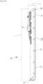
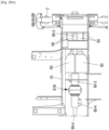
- FIG. 18A And 18B partially represent a variant of the work machine 1.
- the [ Fig.18A ] is a partial sectional view from below of the work machine 1, while the [ Fig.18B ] is a perspective view where one of the side members 10 has been removed in order to make the battery elements 60 visible.
- the battery elements 60 are here six in number, electrically connected in series in pairs as already described above.
- the battery elements 60 are arranged between the two side members 10, and are more specifically housed in a frame 1010 secured to the side members 10.
- the bottom of the frame 1010 is not shown in the Figures 18A And 18B in order to make the battery elements 60 visible.
- the battery cells 60 supply electricity to two electric drive motors 80-3 and 80-4.
- the electric motor 80-3 drives an input shaft of the front axle 3, possibly via a reduction gear (not shown).
- the electric motor 80-4 drives an input shaft of the rear axle 4, possibly via a reduction gear (not shown).
- the output shafts of the electric motors 80-3 and 80-4 are here aligned substantially parallel to the front-rear axis A-A of the work machine 1 and thus to the side members 10.
- This hydraulic cylinder 299 can be driven by a hydraulic pump itself driven by an electric motor (not shown), which is also supplied with electricity by the battery elements 60.
- FIG. 19A And 19B partially represent another variant of the work machine 1.
- the [ Fig.19A ] is a partial sectional view from below of the work machine 1, while the [ Fig.19B ] is a perspective view where one of the side members 10 has been removed in order to make the battery elements 60 visible.
- the battery elements 60 are here eight in number, electrically connected in series in pairs as already described above.
- the battery elements 60 are arranged between the two side members 10, and are more specifically housed in a frame 1060 secured to the side members 10.
- Six of the eight battery elements 60 are stacked one above the other, in pairs.
- the last two battery elements 60 i.e. the ones closest to the single side member 10 visible in the [ Fig.19B ]) are arranged face to face in frame 1060.
- the battery cells 60 supply electricity to two electric drive motors 80-3 and 80-4.
- the electric motor 80-3 drives an input shaft of the front axle 3, possibly via a reduction gear (not shown).
- the electric motor 80-4 drives an input shaft of the rear axle 4, possibly via a reduction gear (not shown).
- the output shafts of the electric motors 80-3 and 80-4 are here aligned substantially parallel to the front-rear axis AA of the work machine 1 and thus to the side members 10.
- the 80-4 propulsion electric motor is located closer to the ground surface than the 80-3 propulsion electric motor.
- FIG. 20A And 20B partially represent yet another variant of the work machine 1.
- the [ Fig.20A ] is a partial sectional view from below of the work machine 1, while the [ Fig.20B ] is a perspective view where one of the side members 10 has been removed in order to make the battery elements 60 visible.
- the battery elements 60 are here ten in number, electrically connected in series in pairs as already described above.
- Four pairs of battery elements 60 are arranged on either side of the shaft 85-3 which will be described later; more precisely, two pairs of battery elements 60 are arranged on each side of the shaft 85-3.
- the fifth pair of battery elements 60 is arranged above these four pairs of battery elements 60 and the shaft 85-3.
- the battery elements 60 are here also received between the two longitudinal members 10, in a frame or a housing which are not shown.
- the battery cells 60 supply electricity to two electric drive motors 80-3 and 80-4.
- the mechanical transmission chain between these electric motors and the axles 3 and 4 is different.
- a reduction gear assembly 81B is arranged between the electric propulsion motors 80-3 and 80-4.
- the reduction gear assembly 81B comprises two reduction gears 83-3 and 83-4, each reduction gear 83-3, 83-4 being covered by a half-casing, the two half-casings being joined and secured so as to form a complete casing of the reduction gear 81B.
- each reduction gear 83-3, 83-4 could be received in a complete casing, the two casings being joined and secured to each other.
- the electric drive motor 80-3 drives, via the reduction gear 83-3, a shaft 85-3 for driving the front axle 3.
- the electric drive motor 80-4 drives, via the reduction gear 83-4, a shaft 85-4 for driving the rear axle 4.
- the shaft 85-3 passes between four pairs of battery cells 60.
- the shaft 85-3 and the shaft 85-4 extend substantially parallel to the front-rear axis AA of the working machine 1 and therefore to the side members 10.
- the shaft 85-3 and the shaft 85-4 are however not necessarily in line with each other. example, in the example shown in the [ Fig.20B ], shaft 85-3 and 85-4 are located in the same plane, but their longitudinal directions form a different angle of 180 degrees. Thus, shaft 85-3 and/or shaft 85-4 may be inclined relative to the ground surface.
- a hydraulic cylinder 299 for lifting the arm 20 It has also been represented on the [ Fig.20B ] a hydraulic cylinder 299 for lifting the arm 20.
- This hydraulic cylinder 299 can be driven by a hydraulic pump itself driven by an electric motor (not shown), which is also supplied with electricity by the battery elements 60.
- the front axle 3 and the rear axle 4 are driven by one or more electric propulsion motors via a mechanical transmission chain.
- other configurations are possible, including a hydraulic transmission chain.
- one or each electric motor can be replaced by a hydraulic motor performing the same function as the electric motor.
- FIG.21 is a functional diagram showing an example of such a hydraulic transmission chain.
- the solid curved lines represent electrical connections
- the dashed curved lines represent a control by a control unit
- the dashed curved lines represent a hydraulic fluid supply.
- a hydraulic motor 803 is coupled to the front axle 3, and a hydraulic motor 804 is coupled to the rear axle 4.
- a hydraulic pump 809 generates a hydraulic flow driving the hydraulic motors 803 and 804.
- the hydraulic pump 809 is driven by an electric motor 380, this electric motor 380 being supplied with electricity by the battery cells 60.
- the electric motor 380 is supplied with electricity by the battery cells 60 via a 380V electric speed controller.
- the 380V electric speed controller is itself electrically connected to the power distribution box 410 described above.
- the 380V electric speed controller can be of the three-phase inverter type. However, other electrical configurations are possible.
- another electric motor 389 drives a hydraulic pump 899.
- the hydraulic pump 899 supplies hydraulic actuators, in a manner known per se as already described above.
- the electric motor 389 is supplied with electricity by the battery cells 60 via an electric speed controller 389V.
- the electric speed controller 389V is itself electrically connected to the power distribution box 410 described above.
- the electric speed controller 389V can be of the three-phase inverter type. However, other electrical configurations are possible.
- a control unit 900 which can also be supplied with electricity by the battery cells 60, controls the actuation of the hydraulic motors 803 and 804, the hydraulic pump 899, and the electric speed variators 380V and 389V.
- Fig.22 partially represents yet another variant of the working machine 1.
- the electric motor 80 drives the front axle 3 via a reduction gear 39 integrated in the front axle 3.
- an input shaft 4-4 of the rear axle 4 is driven via a drive shaft 34 itself driven by the electric motor 80 via the reduction gear 39.
- the front axle 3 is fixed to the plate 100-1 by means of two studs 101-1.
- the studs 101-1 are threaded at their two ends.
- Nuts 102-1 are screwed onto the two ends of the studs 101-1 so as to tighten the plate 100-1 as well as a counter-plate 103-1 (cf. [ Fig.3 ]) against the front axle 3 and thereby hold the front axle 3 firmly in place relative to the side member 10.
- the front axle 3 is fixed identically to the plate 100-2 by means of two studs 101-2 threaded at their two ends, four nuts 102-2 and a counter plate 103-2.
- the rear axle 4 is fixed to the side members 10 via two rear support plates 107, each integral with the two side members 10.
- a radial bearing 108 is fixed, here by bolting, to each of the rear support plates 107.
- the rear axle 4 comprises two journals 104. Each of the journals 104 is received in a radial bearing 108.
- the rear axle 4 is held in position relative to the chassis 2 in the longitudinal direction AA while being capable of pivoting relative to the chassis 2.
- the manner which has just been described of fixing the front axle 3 and the rear axles 4 to the side members 10 can be used in all the previously described variants of the work machine 1.
Landscapes
- Engineering & Computer Science (AREA)
- Transportation (AREA)
- Structural Engineering (AREA)
- Chemical & Material Sciences (AREA)
- Mechanical Engineering (AREA)
- Geology (AREA)
- Life Sciences & Earth Sciences (AREA)
- Civil Engineering (AREA)
- Electrochemistry (AREA)
- Combustion & Propulsion (AREA)
- General Chemical & Material Sciences (AREA)
- Chemical Kinetics & Catalysis (AREA)
- Manufacturing & Machinery (AREA)
- Materials Engineering (AREA)
- Aviation & Aerospace Engineering (AREA)
- Arrangement Or Mounting Of Propulsion Units For Vehicles (AREA)
- Battery Mounting, Suspending (AREA)
Claims (30)
- Arbeitsmaschine (1), umfassend:- ein auf der Bodenfläche verschiebbares Chassis (2), wobei das Chassis zwei zueinander parallele und sich parallel zu einer Längsrichtung (A-A) der Maschine (1) erstreckende Längsträger (10) aufweist; und- einen sich parallel zur Längsrichtung (A-A) der Maschine (1) erstreckenden Hubarm (20), wobei der Hubarm (20) an den beiden und zwischen den beiden Längsträgern (10) derart angelenkt ist, dass er in Bezug auf die beiden Längsträger (10) um eine sich senkrecht zur Längsrichtung (A-A) der Maschine erstreckende Schwenkachse schwenkbeweglich ist;- mindestens zwei Batterieelemente (60); und- mindestens einen Elektromotor (80, 380, 89, 389) für den Antrieb des Chassis (2) und für die Betätigung des Hubarms (20), wobei die Batterieelemente elektrisch mit dem mindestens einen Elektromotor verbunden sind, um Leistung an den mindestens einen Elektromotor zu liefern; wobei die Arbeitsmaschine (1) dadurch gekennzeichnet ist, dass die beiden Batterieelemente zwischen den beiden Längsträgern (10) unter dem Hubarm (20) angeordnet sind.
- Arbeitsmaschine (1) nach Anspruch 1, wobei die Batterieelemente (60) beiderseitig einer Längsmittelachse (A-A) der Arbeitsmaschine und/oder rittlings auf der Längsmittelachse der Arbeitsmaschine angeordnet sind, bevorzugt mit einer im Wesentlichen ausgeglichenen Massenverteilung in Bezug auf die Längsmittelachse.
- Arbeitsmaschine (1) nach Anspruch 1 oder 2, ferner umfassend eine Vorderachse (3), die an einem vorderen Endabschnitt des Chassis (2) montiert ist, und eine Hinterachse (4), die an einem hinteren Endabschnitt des Chassis (2) montiert ist, und mindestens ein Getriebe (81, 82, 83, 84, 809), das den mindestens einen Elektromotor (80, 380) mit mindestens einer von Vorderachse (3) und Hinterachse (4) verbindet.
- Arbeitsmaschine (1) nach Anspruch 3, wobei die Batterieelemente (60) entlang der Längsrichtung zwischen der Vorderachse (3) und der Hinterachse (4) angeordnet sind.
- Arbeitsmaschine (1) nach Anspruch 3 oder 4, wobei der mindestens eine Elektromotor einen elektrischen Antriebsmotor (80, 380) für den Antrieb des Chassis (2) umfasst, wobei die Batterieelemente über einen elektrischen Geschwindigkeitsregler (80V, 380V) mit dem elektrischen Antriebsmotor (80, 380) elektrisch verbunden sind, wobei das Getriebe einen mechanischen oder hydraulischen Antriebsstrang umfasst, der den elektrischen Antriebsmotor mit mindestens einer von Vorderachse (3) und Hinterachse (4) verbindet.
- Arbeitsmaschine (1) nach Anspruch 3 oder 4, wobei der mindestens eine Elektromotor einen ersten elektrischen Antriebsmotor (80-3), der durch einen ersten mechanischen Antriebsstrang mit der Vorderachse (3) verbunden ist, und einen zweiten elektrischen Antriebsmotor (80-4), der durch einen zweiten mechanischen Antriebsstrang mit der Hinterachse (4) verbunden ist, umfasst.
- Arbeitsmaschine (1) nach einem der Ansprüche 3 bis 5, wobei das Getriebe einen hydraulischen Antriebsstrang umfasst, der den mindestens einen Elektromotor (380) mit mindestens einer von Vorderachse (3) und Hinterachse (4) verbindet, wobei der hydraulische Antriebsstrang mindestens eine Hydraulikpumpe (809) umfasst, die durch den mindestens einen Elektromotor (380) angetrieben wird, und mindestens einen Hydraulikmotor (803, 804), der durch einen von der Hydraulikpumpe erzeugten Hydraulikfluss angetrieben wird, wobei der mindestens eine Hydraulikmotor (803, 804) mit mindestens einer von Vorderachse (3) und Hinterachse (4) verbunden ist.
- Arbeitsmaschine (1) nach einem der Ansprüche 1 bis 7, wobei der mindestens eine Elektromotor einen elektrischen Betätigungsmotor (89, 389) zur Betätigung des Hubarms (20) umfasst, wobei die Batterieelemente über einen elektrischen Geschwindigkeitsregler (89V, 389V) mit dem elektrischen Betätigungsmotor (89) verbunden sind.
- Arbeitsmaschine (1) nach Anspruch 8, wobei der elektrische Betätigungsmotor (89) mindestens einen Elektrozylinder umfasst, der ausgebildet ist zum Aktivieren einer Bewegung des Hubarms (20).
- Arbeitsmaschine (1) nach Anspruch 8 oder 9, ferner umfassend eine Hydraulikpumpe (899), die mit dem elektrischen Betätigungsmotor (89, 389) verbunden ist, und einen hydraulischen Aktuator (299), der von der Hydraulikpumpe gespeist wird, um mindestens eine Bewegung des Hubarms (20) zu aktivieren.
- Arbeitsmaschine (1) nach einem der Ansprüche 1 bis 10, ferner umfassend eine Kabine (29) für einen Maschinenführer, wobei die Kabine an einer Seitenwand des Chassis der Arbeitsmaschine vorspringend angeordnet ist.
- Arbeitsmaschine (1) nach einem der Ansprüche 1 bis 11, wobei das Chassis (2) ein Gehäuse (12) zur Aufnahme der Batterieelemente aufweist, wobei das Gehäuse (12) eine Öffnung (13) hat, die in eine gewählte Richtung mündet, nämlich zur Vorderseite des Arbeitsgeräts, zur Rückseite des Arbeitsgeräts, zur Oberseite des Chassis, zur Unterseite des Chassis oder in eine seitliche Richtung entgegengesetzt zu einer Kabine der Arbeitsmaschine.
- Arbeitsmaschine (1) nach Anspruch 12, wobei das Gehäuse (12) eine Unterseite (14) hat, auf der die Batterieelemente direkt oder indirekt aufliegen, wobei die Unterseite (14) in einer von der Öffnung (13) wegführenden Richtung zur Bodenfläche geneigt ist.
- Arbeitsmaschine (1) nach Anspruch 12 oder 13, wobei die Öffnung (13) des Gehäuses (12) mit einem Lüftungsgitter verschlossen ist.
- Arbeitsmaschine (1) nach einem der Ansprüche 12 bis 14, wobei das Gehäuse (12) eine von der Öffnung entfernte Belüftungsöffnung aufweist.
- Arbeitsmaschine (1) nach einem der Ansprüche 1 bis 15, ferner umfassend zusätzliche Batterieelemente zum Liefern elektrischer Leistung an den wenigstens einen Elektromotor (80, 89) der Arbeitsmaschine, wobei die zusätzlichen Batterieelemente zwischen den beiden Längsträgern (10) angeordnet sind und wobei das Chassis (2) ein die zusätzlichen Batterieelemente aufnehmendes zusätzliches Gehäuse (112) aufweist, wobei das zusätzliche Gehäuse (112) eine Öffnung hat, die in Richtung zur Rückseite der Arbeitsmaschine mündet, und eine Unterseite (114), auf der die Batterieelemente direkt oder indirekt aufliegen.
- Arbeitsmaschine (1) nach einem der Ansprüche 1 bis 16, wobei die wenigstens zwei Batterieelemente (60) Teil eines insgesamt quaderförmigen Batteriesatzes (40) sind, wobei der Batteriesatz (40) eine Stützplatte aufweist, wobei die wenigstens zwei Batterieelemente (60) in Bezug auf eine Höhenrichtung des Batteriesatzes (40) auf einer Oberseite der Stützplatte befestigt sind und wobei der Batteriesatz (40) eine größere Breite ℓ in einer Breitenrichtung des Batteriesatzes, eine größere Länge L in einer Längsrichtung des Batteriesatzes und eine größere Höhe h in der Höhenrichtung des Batteriesatzes aufweist, wobei die größere Länge L größer als die größere Breite ℓ ist und wobei die größere Länge L und die größere Höhe h die Ungleichung h/L ≤ 0,40 erfüllen.
- Arbeitsmaschine (1) nach Anspruch 17, wobei der Batteriesatz (40) ferner umfasst:- eine elektrische Anschlussbox (50), die mit den Batterieelementen (60) elektrisch verbunden ist; und- eine Leistungsausgangsbuchse (51), die mit einem Ausgang der elektrischen Anschlussbox (50) elektrisch verbunden und mit einer Leistungseingangsbuchse (400) des Arbeitsfahrzeugs (1) elektrisch verbindbar ist.
- Arbeitsmaschine (1) nach Anspruch 17 oder 18, wobei die größere Breite ℓ und die größere Höhe h die Ungleichung h/f ≤ 0,60 erfüllen.
- Arbeitsmaschine (1) nach einem der Ansprüche 17 bis 19, wobei die größere Länge L und die größere Breite ℓ die Ungleichung ℓ/L ≤ 0,30 erfüllen.
- Arbeitsmaschine (1) nach einem der Ansprüche 17 bis 20, wobei die Stützplatte (41) auf einer Unterseite (41B), die der Oberseite (41A) gegenüberliegt, an der die Batteriezellen (60) befestigt sind, eine Vielzahl von Polymerschuhen aufweist.
- Arbeitsmaschine (1) nach einem der Ansprüche 17 bis 21, wobei die Stützplatte (41) in Längsrichtung an einem ihrer Enden zwei Durchgangsöffnungen (49) aufweist, wobei die Durchgangsöffnungen (49) derart dimensioniert sind, dass sie einer Bedienungsperson erlauben, den Batteriesatz an diesem Ende anzuheben, indem sie die Stützplatte über die beiden Durchgangsöffnungen greift.
- Arbeitsmaschine (1) nach einem der Ansprüche 17 bis 22, wobei die Stützplatte (41) eine Mehrzahl von in der Breitenrichtung und/oder in der Längenrichtung vorspringenden Elementen (115) aufweist, die dazu eingerichtet sind, mit Anschlagelementen (120) zusammenzuwirken.
- Arbeitsmaschine (1) nach einem der Ansprüche 17 bis 23, wobei die Batterieelemente (60) Lithium-Ionen-Batterieelemente sind.
- Arbeitsmaschine (1) nach einem der Ansprüche 17 bis 24, wobei das Chassis ein den Batteriesatz aufnehmendes Gehäuse (12, 112) aufweist, wobei das Gehäuse (12, 112) eine Öffnung hat, die in die Vorderseite oder in die Rückseite der Arbeitsmaschine mündet, und eine Unterseite, auf welcher der Batteriesatz direkt oder indirekt aufliegt.
- Arbeitsmaschine (1) nach Anspruch 25, wobei die Unterseite des Gehäuses (12, 112) in einer von der Öffnung des Gehäuses wegführenden Richtung zur Bodenfläche geneigt ist.
- Arbeitsmaschine (1) nach Anspruch 25 oder 26, wobei das Gehäuse (12) eine der Unterseite (14) gegenüberliegende Oberseite (15) hat, wobei die Oberseite eine geneigte Fläche (16) derart aufweist, dass sich ein Querschnitt des Gehäuses (12) in Richtung auf die Öffnung (13) vergrößert.
- Arbeitsmaschine (1) nach einem der Ansprüche 17 bis 27, wobei der Batteriesatz (40) ferner mindestens eine Rolle (79) aufweist, die frei drehbar auf einer Oberseite des Batteriesatzes (40) montiert ist, wobei die Rolle (79) dazu eingerichtet ist, mit der geneigten Fläche (16) zusammenzuwirken, wenn der Batteriesatz (40) durch die Öffnung (13) des Gehäuses (12) aus dem Gehäuse (12) herausgezogen wird.
- Arbeitsmaschine (1) nach einem der Ansprüche 17 bis 28, wobei die Stützplatte (41) eine Mehrzahl von Schlitzen (47) aufweist und die Schlitze in Richtung der Länge des Batteriesatzes (40) zueinander ausgerichtet sind und wobei das Chassis in der Nähe der Öffnung des Gehäuses eine Welle (200) aufweist und die Welle ein Zahnrad (201) trägt, das derart ausgebildet ist, dass es mit den Schlitzen (47) der Stützplatte (41) zusammenwirken und solchermaßen die Stützplatte (41) translatorisch bewegen kann, wenn die Welle (200) gedreht wird.
- Arbeitsmaschine (1) nach einem der Ansprüche 17 bis 29, wobei der Batteriesatz (40) ferner an einem Längsende desselben einen vorspringenden Klotz (59) aufweist, der in einer Zentrieröffnung aufgenommen wird, die sich an einem der Öffnung (13) des Gehäuses (12) gegenüberliegenden Ende des Gehäuses (12) befindet.
Applications Claiming Priority (3)
| Application Number | Priority Date | Filing Date | Title |
|---|---|---|---|
| FR2107831A FR3125638B1 (fr) | 2021-07-20 | 2021-07-20 | Ensemble de batteries pour un engin de travail |
| FR2107830A FR3125521B1 (fr) | 2021-07-20 | 2021-07-20 | Engin de travail comprenant des éléments de batterie |
| PCT/EP2022/069356 WO2023001621A1 (fr) | 2021-07-20 | 2022-07-11 | Engin de travail comprenant des éléments de batterie |
Publications (2)
| Publication Number | Publication Date |
|---|---|
| EP4373778A1 EP4373778A1 (de) | 2024-05-29 |
| EP4373778B1 true EP4373778B1 (de) | 2025-01-29 |
Family
ID=82492455
Family Applications (1)
| Application Number | Title | Priority Date | Filing Date |
|---|---|---|---|
| EP22740928.1A Active EP4373778B1 (de) | 2021-07-20 | 2022-07-11 | Arbeitsmaschine mit batterieelemente |
Country Status (3)
| Country | Link |
|---|---|
| EP (1) | EP4373778B1 (de) |
| ES (1) | ES3014445T3 (de) |
| WO (1) | WO2023001621A1 (de) |
Families Citing this family (9)
| Publication number | Priority date | Publication date | Assignee | Title |
|---|---|---|---|---|
| FR3137874B1 (fr) * | 2022-07-18 | 2024-05-31 | Manitou Bf | Engin de travail avec une cabine située latéralement et un module de batteries fixé sous la cabine |
| GB2625762B (en) * | 2022-12-22 | 2026-04-22 | Bamford Excavators Ltd | A working machine |
| FR3145557B1 (fr) * | 2023-02-06 | 2025-01-10 | Manitou Bf | Machine de manutention comportant un module de puissance et un mécanisme de dépose du module de puissance |
| IT202300020538A1 (it) * | 2023-10-04 | 2025-04-04 | Dieci S R L | Sollevatore telescopico a propulsione elettrica |
| IT202300020526A1 (it) * | 2023-10-04 | 2025-04-04 | Dieci S R L | Sollevatore telescopico a propulsione elettrica |
| DE102023209885A1 (de) * | 2023-10-10 | 2025-04-10 | Volkswagen Aktiengesellschaft | Batterie-Wechselsystem, Kraftfahrzeug mit dem Batterie-Wechselsystem sowie Verfahren zum Ein- und/oder Ausbau einer Batterie in oder aus dem Batterie-Wechselsystem |
| GB2639193A (en) * | 2024-03-07 | 2025-09-17 | Bamford Excavators Ltd | A working machine |
| DE102024205855A1 (de) * | 2024-06-24 | 2025-12-24 | Volkswagen Aktiengesellschaft | Batterie-Wechselsystem, Kraftfahrzeug mit dem Batterie-Wechselsystem sowie Verfahren zum Ein- und/oder Ausbau einer Batterie in oder aus dem Batterie Wechselsystem |
| FR3166626A1 (fr) * | 2024-09-23 | 2026-03-27 | Manitou Bf | Engin de manutention électrique alimenté par une batterie |
Family Cites Families (5)
| Publication number | Priority date | Publication date | Assignee | Title |
|---|---|---|---|---|
| JP2005262978A (ja) | 2004-03-17 | 2005-09-29 | Hitachi Constr Mach Co Ltd | 作業機械およびその製造方法 |
| KR20150053284A (ko) * | 2013-11-07 | 2015-05-18 | 주식회사 호룡 | 자주식 크레인 |
| GB2572356B (en) * | 2018-03-27 | 2022-09-14 | Bamford Excavators Ltd | Load-handling vehicle |
| US11541742B2 (en) * | 2018-11-16 | 2023-01-03 | Northern Valley Machine Inc. | Mobile omnidirectional device |
| CN112072008B (zh) * | 2019-06-10 | 2021-07-13 | 宁德时代新能源科技股份有限公司 | 电池包和车辆 |
-
2022
- 2022-07-11 WO PCT/EP2022/069356 patent/WO2023001621A1/fr not_active Ceased
- 2022-07-11 ES ES22740928T patent/ES3014445T3/es active Active
- 2022-07-11 EP EP22740928.1A patent/EP4373778B1/de active Active
Also Published As
| Publication number | Publication date |
|---|---|
| WO2023001621A1 (fr) | 2023-01-26 |
| ES3014445T3 (en) | 2025-04-22 |
| EP4373778A1 (de) | 2024-05-29 |
Similar Documents
| Publication | Publication Date | Title |
|---|---|---|
| WO2023001621A1 (fr) | Engin de travail comprenant des éléments de batterie | |
| EP4309937B1 (de) | Arbeitsmaschine mit einer seitlich angeordneten kabine und einem unter der kabine befestigten batteriemodul | |
| EP2370283B1 (de) | Mit einer durch eine vertikalbewegung ausbaubaren energieversorgungsbatterie versehenes kraftfahrzeug und vorrichtung zum installieren und ausbauen solch einer batterie | |
| FR3018226B1 (fr) | Machine de travail diesel-electrique, notamment camion a benne | |
| EP3377351A1 (de) | Elektrisches landfahrzeug für den öffentlichen verkehr mit optimierter architektur | |
| EP2404811B1 (de) | Selbstfahrendes Werkzeugträger-Fahrzeug | |
| FR2985484A1 (fr) | Dispositif de montage et de demontage de batterie de vehicule avec cables elastiques pour compenser les ecarts d'assiette de vehicule | |
| FR2961771A1 (fr) | Procede de montage d'un bac de batterie et de l'electronique de puissance dans un vehicule et procede de demontage du bac de batterie | |
| FR3125638A1 (fr) | Ensemble de batteries pour un engin de travail | |
| FR3018797A1 (fr) | Machine de levage de poids, comprenant un dispositif de fleche de grue et un dispositif de contrepoids | |
| FR3018230A1 (de) | ||
| CA2728143A1 (en) | Cleaning machine | |
| FR3043601B1 (fr) | Vehicule electrique terrestre de transport en commun, de type bus, muni de modules de stockage d'energie electrique rechargeables. | |
| EP2532547B1 (de) | Fahrgestellstruktur zur Aufnahme eines Fahrzeuginnenraums eines Kraftfahrzeugs mit Elektroantrieb, und mit einer solchen Fahrgestellstruktur ausgestattetes Kraftfahrzeug | |
| EP4685099A1 (de) | Handhabungsmaschine | |
| FR3125521A1 (fr) | Engin de travail comprenant des éléments de batterie | |
| FR2560566A1 (fr) | Chargeur a courroie de faible hauteur pour avions | |
| FR3082791A1 (fr) | Vehicule pour transport de conteneur a moteur electrique et a batterie | |
| WO2023198797A1 (fr) | Engin de travail avec transmission à joint universel | |
| FR2977837A1 (fr) | Berceau pour vehicule automobile electrique ou hybride | |
| WO2024126557A1 (fr) | Nacelle élévatrice à motorisation électrique | |
| EP4410736B1 (de) | Handhabungsmaschine mit einem leistungsmodul und einem mechanismus zum entfernen des leistungsmoduls | |
| EP4334005B1 (de) | Fahrzeug für einen achterbahn | |
| FR3096106A1 (fr) | Dispositif d’entrainement de vehicule | |
| FR3128685A1 (fr) | Structure de rigidification d’un chassis de vehicule automobile |
Legal Events
| Date | Code | Title | Description |
|---|---|---|---|
| STAA | Information on the status of an ep patent application or granted ep patent |
Free format text: STATUS: UNKNOWN |
|
| STAA | Information on the status of an ep patent application or granted ep patent |
Free format text: STATUS: THE INTERNATIONAL PUBLICATION HAS BEEN MADE |
|
| PUAI | Public reference made under article 153(3) epc to a published international application that has entered the european phase |
Free format text: ORIGINAL CODE: 0009012 |
|
| STAA | Information on the status of an ep patent application or granted ep patent |
Free format text: STATUS: REQUEST FOR EXAMINATION WAS MADE |
|
| 17P | Request for examination filed |
Effective date: 20240115 |
|
| AK | Designated contracting states |
Kind code of ref document: A1 Designated state(s): AL AT BE BG CH CY CZ DE DK EE ES FI FR GB GR HR HU IE IS IT LI LT LU LV MC MK MT NL NO PL PT RO RS SE SI SK SM TR |
|
| REG | Reference to a national code |
Ref country code: DE Ref legal event code: R079 Free format text: PREVIOUS MAIN CLASS: B66F0009065000 Ipc: B60K0001000000 Ref country code: DE Ref legal event code: R079 Ref document number: 602022010252 Country of ref document: DE Free format text: PREVIOUS MAIN CLASS: B66F0009065000 Ipc: B60K0001000000 |
|
| GRAP | Despatch of communication of intention to grant a patent |
Free format text: ORIGINAL CODE: EPIDOSNIGR1 |
|
| STAA | Information on the status of an ep patent application or granted ep patent |
Free format text: STATUS: GRANT OF PATENT IS INTENDED |
|
| RIC1 | Information provided on ipc code assigned before grant |
Ipc: H01M 50/249 20210101ALI20240906BHEP Ipc: B60K 1/04 20190101ALI20240906BHEP Ipc: B66F 9/065 20060101ALI20240906BHEP Ipc: B66F 9/075 20060101ALI20240906BHEP Ipc: H01M 50/244 20210101ALI20240906BHEP Ipc: H01M 10/0525 20100101ALI20240906BHEP Ipc: B60K 17/356 20060101ALI20240906BHEP Ipc: B60K 17/344 20060101ALI20240906BHEP Ipc: B60K 17/22 20060101ALI20240906BHEP Ipc: B60K 1/00 20060101AFI20240906BHEP |
|
| DAV | Request for validation of the european patent (deleted) | ||
| DAX | Request for extension of the european patent (deleted) | ||
| INTG | Intention to grant announced |
Effective date: 20241010 |
|
| GRAS | Grant fee paid |
Free format text: ORIGINAL CODE: EPIDOSNIGR3 |
|
| GRAA | (expected) grant |
Free format text: ORIGINAL CODE: 0009210 |
|
| STAA | Information on the status of an ep patent application or granted ep patent |
Free format text: STATUS: THE PATENT HAS BEEN GRANTED |
|
| P01 | Opt-out of the competence of the unified patent court (upc) registered |
Free format text: CASE NUMBER: APP_62841/2024 Effective date: 20241126 |
|
| AK | Designated contracting states |
Kind code of ref document: B1 Designated state(s): AL AT BE BG CH CY CZ DE DK EE ES FI FR GB GR HR HU IE IS IT LI LT LU LV MC MK MT NL NO PL PT RO RS SE SI SK SM TR |
|
| REG | Reference to a national code |
Ref country code: GB Ref legal event code: FG4D Free format text: NOT ENGLISH |
|
| REG | Reference to a national code |
Ref country code: CH Ref legal event code: EP |
|
| REG | Reference to a national code |
Ref country code: DE Ref legal event code: R096 Ref document number: 602022010252 Country of ref document: DE |
|
| REG | Reference to a national code |
Ref country code: IE Ref legal event code: FG4D Free format text: LANGUAGE OF EP DOCUMENT: FRENCH |
|
| REG | Reference to a national code |
Ref country code: ES Ref legal event code: FG2A Ref document number: 3014445 Country of ref document: ES Kind code of ref document: T3 Effective date: 20250422 |
|
| REG | Reference to a national code |
Ref country code: NL Ref legal event code: MP Effective date: 20250129 |
|
| PG25 | Lapsed in a contracting state [announced via postgrant information from national office to epo] |
Ref country code: NL Free format text: LAPSE BECAUSE OF FAILURE TO SUBMIT A TRANSLATION OF THE DESCRIPTION OR TO PAY THE FEE WITHIN THE PRESCRIBED TIME-LIMIT Effective date: 20250129 |
|
| PG25 | Lapsed in a contracting state [announced via postgrant information from national office to epo] |
Ref country code: RS Free format text: LAPSE BECAUSE OF FAILURE TO SUBMIT A TRANSLATION OF THE DESCRIPTION OR TO PAY THE FEE WITHIN THE PRESCRIBED TIME-LIMIT Effective date: 20250429 |
|
| PG25 | Lapsed in a contracting state [announced via postgrant information from national office to epo] |
Ref country code: FI Free format text: LAPSE BECAUSE OF FAILURE TO SUBMIT A TRANSLATION OF THE DESCRIPTION OR TO PAY THE FEE WITHIN THE PRESCRIBED TIME-LIMIT Effective date: 20250129 |
|
| PG25 | Lapsed in a contracting state [announced via postgrant information from national office to epo] |
Ref country code: PL Free format text: LAPSE BECAUSE OF FAILURE TO SUBMIT A TRANSLATION OF THE DESCRIPTION OR TO PAY THE FEE WITHIN THE PRESCRIBED TIME-LIMIT Effective date: 20250129 |
|
| REG | Reference to a national code |
Ref country code: LT Ref legal event code: MG9D |
|
| PG25 | Lapsed in a contracting state [announced via postgrant information from national office to epo] |
Ref country code: IS Free format text: LAPSE BECAUSE OF FAILURE TO SUBMIT A TRANSLATION OF THE DESCRIPTION OR TO PAY THE FEE WITHIN THE PRESCRIBED TIME-LIMIT Effective date: 20250529 Ref country code: NO Free format text: LAPSE BECAUSE OF FAILURE TO SUBMIT A TRANSLATION OF THE DESCRIPTION OR TO PAY THE FEE WITHIN THE PRESCRIBED TIME-LIMIT Effective date: 20250429 |
|
| REG | Reference to a national code |
Ref country code: AT Ref legal event code: MK05 Ref document number: 1763126 Country of ref document: AT Kind code of ref document: T Effective date: 20250129 |
|
| PG25 | Lapsed in a contracting state [announced via postgrant information from national office to epo] |
Ref country code: HR Free format text: LAPSE BECAUSE OF FAILURE TO SUBMIT A TRANSLATION OF THE DESCRIPTION OR TO PAY THE FEE WITHIN THE PRESCRIBED TIME-LIMIT Effective date: 20250129 |
|
| PG25 | Lapsed in a contracting state [announced via postgrant information from national office to epo] |
Ref country code: LV Free format text: LAPSE BECAUSE OF FAILURE TO SUBMIT A TRANSLATION OF THE DESCRIPTION OR TO PAY THE FEE WITHIN THE PRESCRIBED TIME-LIMIT Effective date: 20250129 Ref country code: PT Free format text: LAPSE BECAUSE OF FAILURE TO SUBMIT A TRANSLATION OF THE DESCRIPTION OR TO PAY THE FEE WITHIN THE PRESCRIBED TIME-LIMIT Effective date: 20250529 |
|
| PG25 | Lapsed in a contracting state [announced via postgrant information from national office to epo] |
Ref country code: BG Free format text: LAPSE BECAUSE OF FAILURE TO SUBMIT A TRANSLATION OF THE DESCRIPTION OR TO PAY THE FEE WITHIN THE PRESCRIBED TIME-LIMIT Effective date: 20250129 Ref country code: GR Free format text: LAPSE BECAUSE OF FAILURE TO SUBMIT A TRANSLATION OF THE DESCRIPTION OR TO PAY THE FEE WITHIN THE PRESCRIBED TIME-LIMIT Effective date: 20250430 |
|
| PG25 | Lapsed in a contracting state [announced via postgrant information from national office to epo] |
Ref country code: AT Free format text: LAPSE BECAUSE OF FAILURE TO SUBMIT A TRANSLATION OF THE DESCRIPTION OR TO PAY THE FEE WITHIN THE PRESCRIBED TIME-LIMIT Effective date: 20250129 |
|
| PG25 | Lapsed in a contracting state [announced via postgrant information from national office to epo] |
Ref country code: SE Free format text: LAPSE BECAUSE OF FAILURE TO SUBMIT A TRANSLATION OF THE DESCRIPTION OR TO PAY THE FEE WITHIN THE PRESCRIBED TIME-LIMIT Effective date: 20250129 |
|
| PG25 | Lapsed in a contracting state [announced via postgrant information from national office to epo] |
Ref country code: SM Free format text: LAPSE BECAUSE OF FAILURE TO SUBMIT A TRANSLATION OF THE DESCRIPTION OR TO PAY THE FEE WITHIN THE PRESCRIBED TIME-LIMIT Effective date: 20250129 |
|
| PGFP | Annual fee paid to national office [announced via postgrant information from national office to epo] |
Ref country code: ES Payment date: 20250811 Year of fee payment: 4 |
|
| PG25 | Lapsed in a contracting state [announced via postgrant information from national office to epo] |
Ref country code: DK Free format text: LAPSE BECAUSE OF FAILURE TO SUBMIT A TRANSLATION OF THE DESCRIPTION OR TO PAY THE FEE WITHIN THE PRESCRIBED TIME-LIMIT Effective date: 20250129 |
|
| PGFP | Annual fee paid to national office [announced via postgrant information from national office to epo] |
Ref country code: DE Payment date: 20250711 Year of fee payment: 4 |
|
| PGFP | Annual fee paid to national office [announced via postgrant information from national office to epo] |
Ref country code: IT Payment date: 20250731 Year of fee payment: 4 |
|
| PGFP | Annual fee paid to national office [announced via postgrant information from national office to epo] |
Ref country code: FR Payment date: 20250730 Year of fee payment: 4 |
|
| PG25 | Lapsed in a contracting state [announced via postgrant information from national office to epo] |
Ref country code: EE Free format text: LAPSE BECAUSE OF FAILURE TO SUBMIT A TRANSLATION OF THE DESCRIPTION OR TO PAY THE FEE WITHIN THE PRESCRIBED TIME-LIMIT Effective date: 20250129 Ref country code: CZ Free format text: LAPSE BECAUSE OF FAILURE TO SUBMIT A TRANSLATION OF THE DESCRIPTION OR TO PAY THE FEE WITHIN THE PRESCRIBED TIME-LIMIT Effective date: 20250129 |
|
| PG25 | Lapsed in a contracting state [announced via postgrant information from national office to epo] |
Ref country code: RO Free format text: LAPSE BECAUSE OF FAILURE TO SUBMIT A TRANSLATION OF THE DESCRIPTION OR TO PAY THE FEE WITHIN THE PRESCRIBED TIME-LIMIT Effective date: 20250129 |
|
| PG25 | Lapsed in a contracting state [announced via postgrant information from national office to epo] |
Ref country code: SK Free format text: LAPSE BECAUSE OF FAILURE TO SUBMIT A TRANSLATION OF THE DESCRIPTION OR TO PAY THE FEE WITHIN THE PRESCRIBED TIME-LIMIT Effective date: 20250129 |
|
| REG | Reference to a national code |
Ref country code: DE Ref legal event code: R097 Ref document number: 602022010252 Country of ref document: DE |
|
| PLBE | No opposition filed within time limit |
Free format text: ORIGINAL CODE: 0009261 |
|
| STAA | Information on the status of an ep patent application or granted ep patent |
Free format text: STATUS: NO OPPOSITION FILED WITHIN TIME LIMIT |
|
| REG | Reference to a national code |
Ref country code: CH Ref legal event code: L10 Free format text: ST27 STATUS EVENT CODE: U-0-0-L10-L00 (AS PROVIDED BY THE NATIONAL OFFICE) Effective date: 20251210 |
|
| 26N | No opposition filed |
Effective date: 20251030 |
|
| REG | Reference to a national code |
Ref country code: CH Ref legal event code: H13 Free format text: ST27 STATUS EVENT CODE: U-0-0-H10-H13 (AS PROVIDED BY THE NATIONAL OFFICE) Effective date: 20260224 |
|
| PG25 | Lapsed in a contracting state [announced via postgrant information from national office to epo] |
Ref country code: LU Free format text: LAPSE BECAUSE OF NON-PAYMENT OF DUE FEES Effective date: 20250711 |
|
| REG | Reference to a national code |
Ref country code: BE Ref legal event code: MM Effective date: 20250731 |
|
| PG25 | Lapsed in a contracting state [announced via postgrant information from national office to epo] |
Ref country code: BE Free format text: LAPSE BECAUSE OF NON-PAYMENT OF DUE FEES Effective date: 20250731 |
|
| PG25 | Lapsed in a contracting state [announced via postgrant information from national office to epo] |
Ref country code: CH Free format text: LAPSE BECAUSE OF NON-PAYMENT OF DUE FEES Effective date: 20250731 |