US11541742B2 - Mobile omnidirectional device - Google Patents
Mobile omnidirectional device Download PDFInfo
- Publication number
- US11541742B2 US11541742B2 US16/684,821 US201916684821A US11541742B2 US 11541742 B2 US11541742 B2 US 11541742B2 US 201916684821 A US201916684821 A US 201916684821A US 11541742 B2 US11541742 B2 US 11541742B2
- Authority
- US
- United States
- Prior art keywords
- mobile omnidirectional
- controller
- mobile
- omnidirectional device
- jib
- Prior art date
- Legal status (The legal status is an assumption and is not a legal conclusion. Google has not performed a legal analysis and makes no representation as to the accuracy of the status listed.)
- Active, expires
Links
- 238000005096 rolling process Methods 0.000 abstract description 16
- 230000001419 dependent effect Effects 0.000 description 10
- 238000010586 diagram Methods 0.000 description 2
- 238000003801 milling Methods 0.000 description 1
Images


Classifications
-
- B—PERFORMING OPERATIONS; TRANSPORTING
- B60—VEHICLES IN GENERAL
- B60B—VEHICLE WHEELS; CASTORS; AXLES FOR WHEELS OR CASTORS; INCREASING WHEEL ADHESION
- B60B19/00—Wheels not otherwise provided for or having characteristics specified in one of the subgroups of this group
- B60B19/003—Multidirectional wheels
-
- B—PERFORMING OPERATIONS; TRANSPORTING
- B60—VEHICLES IN GENERAL
- B60K—ARRANGEMENT OR MOUNTING OF PROPULSION UNITS OR OF TRANSMISSIONS IN VEHICLES; ARRANGEMENT OR MOUNTING OF PLURAL DIVERSE PRIME-MOVERS IN VEHICLES; AUXILIARY DRIVES FOR VEHICLES; INSTRUMENTATION OR DASHBOARDS FOR VEHICLES; ARRANGEMENTS IN CONNECTION WITH COOLING, AIR INTAKE, GAS EXHAUST OR FUEL SUPPLY OF PROPULSION UNITS IN VEHICLES
- B60K1/00—Arrangement or mounting of electrical propulsion units
- B60K1/04—Arrangement or mounting of electrical propulsion units of the electric storage means for propulsion
-
- B—PERFORMING OPERATIONS; TRANSPORTING
- B60—VEHICLES IN GENERAL
- B60K—ARRANGEMENT OR MOUNTING OF PROPULSION UNITS OR OF TRANSMISSIONS IN VEHICLES; ARRANGEMENT OR MOUNTING OF PLURAL DIVERSE PRIME-MOVERS IN VEHICLES; AUXILIARY DRIVES FOR VEHICLES; INSTRUMENTATION OR DASHBOARDS FOR VEHICLES; ARRANGEMENTS IN CONNECTION WITH COOLING, AIR INTAKE, GAS EXHAUST OR FUEL SUPPLY OF PROPULSION UNITS IN VEHICLES
- B60K17/00—Arrangement or mounting of transmissions in vehicles
- B60K17/04—Arrangement or mounting of transmissions in vehicles characterised by arrangement, location, or kind of gearing
- B60K17/043—Transmission unit disposed in on near the vehicle wheel, or between the differential gear unit and the wheel
-
- B—PERFORMING OPERATIONS; TRANSPORTING
- B60—VEHICLES IN GENERAL
- B60K—ARRANGEMENT OR MOUNTING OF PROPULSION UNITS OR OF TRANSMISSIONS IN VEHICLES; ARRANGEMENT OR MOUNTING OF PLURAL DIVERSE PRIME-MOVERS IN VEHICLES; AUXILIARY DRIVES FOR VEHICLES; INSTRUMENTATION OR DASHBOARDS FOR VEHICLES; ARRANGEMENTS IN CONNECTION WITH COOLING, AIR INTAKE, GAS EXHAUST OR FUEL SUPPLY OF PROPULSION UNITS IN VEHICLES
- B60K17/00—Arrangement or mounting of transmissions in vehicles
- B60K17/34—Arrangement or mounting of transmissions in vehicles for driving both front and rear wheels, e.g. four wheel drive vehicles
- B60K17/354—Arrangement or mounting of transmissions in vehicles for driving both front and rear wheels, e.g. four wheel drive vehicles having separate mechanical assemblies for transmitting drive to the front or to the rear wheels or set of wheels
-
- B—PERFORMING OPERATIONS; TRANSPORTING
- B60—VEHICLES IN GENERAL
- B60K—ARRANGEMENT OR MOUNTING OF PROPULSION UNITS OR OF TRANSMISSIONS IN VEHICLES; ARRANGEMENT OR MOUNTING OF PLURAL DIVERSE PRIME-MOVERS IN VEHICLES; AUXILIARY DRIVES FOR VEHICLES; INSTRUMENTATION OR DASHBOARDS FOR VEHICLES; ARRANGEMENTS IN CONNECTION WITH COOLING, AIR INTAKE, GAS EXHAUST OR FUEL SUPPLY OF PROPULSION UNITS IN VEHICLES
- B60K17/00—Arrangement or mounting of transmissions in vehicles
- B60K17/34—Arrangement or mounting of transmissions in vehicles for driving both front and rear wheels, e.g. four wheel drive vehicles
- B60K17/356—Arrangement or mounting of transmissions in vehicles for driving both front and rear wheels, e.g. four wheel drive vehicles having fluid or electric motor, for driving one or more wheels
-
- B—PERFORMING OPERATIONS; TRANSPORTING
- B60—VEHICLES IN GENERAL
- B60K—ARRANGEMENT OR MOUNTING OF PROPULSION UNITS OR OF TRANSMISSIONS IN VEHICLES; ARRANGEMENT OR MOUNTING OF PLURAL DIVERSE PRIME-MOVERS IN VEHICLES; AUXILIARY DRIVES FOR VEHICLES; INSTRUMENTATION OR DASHBOARDS FOR VEHICLES; ARRANGEMENTS IN CONNECTION WITH COOLING, AIR INTAKE, GAS EXHAUST OR FUEL SUPPLY OF PROPULSION UNITS IN VEHICLES
- B60K7/00—Disposition of motor in, or adjacent to, traction wheel
- B60K7/0007—Disposition of motor in, or adjacent to, traction wheel the motor being electric
-
- B—PERFORMING OPERATIONS; TRANSPORTING
- B60—VEHICLES IN GENERAL
- B60L—PROPULSION OF ELECTRICALLY-PROPELLED VEHICLES; SUPPLYING ELECTRIC POWER FOR AUXILIARY EQUIPMENT OF ELECTRICALLY-PROPELLED VEHICLES; ELECTRODYNAMIC BRAKE SYSTEMS FOR VEHICLES IN GENERAL; MAGNETIC SUSPENSION OR LEVITATION FOR VEHICLES; MONITORING OPERATING VARIABLES OF ELECTRICALLY-PROPELLED VEHICLES; ELECTRIC SAFETY DEVICES FOR ELECTRICALLY-PROPELLED VEHICLES
- B60L50/00—Electric propulsion with power supplied within the vehicle
- B60L50/50—Electric propulsion with power supplied within the vehicle using propulsion power supplied by batteries or fuel cells
- B60L50/60—Electric propulsion with power supplied within the vehicle using propulsion power supplied by batteries or fuel cells using power supplied by batteries
-
- B—PERFORMING OPERATIONS; TRANSPORTING
- B60—VEHICLES IN GENERAL
- B60L—PROPULSION OF ELECTRICALLY-PROPELLED VEHICLES; SUPPLYING ELECTRIC POWER FOR AUXILIARY EQUIPMENT OF ELECTRICALLY-PROPELLED VEHICLES; ELECTRODYNAMIC BRAKE SYSTEMS FOR VEHICLES IN GENERAL; MAGNETIC SUSPENSION OR LEVITATION FOR VEHICLES; MONITORING OPERATING VARIABLES OF ELECTRICALLY-PROPELLED VEHICLES; ELECTRIC SAFETY DEVICES FOR ELECTRICALLY-PROPELLED VEHICLES
- B60L53/00—Methods of charging batteries, specially adapted for electric vehicles; Charging stations or on-board charging equipment therefor; Exchange of energy storage elements in electric vehicles
- B60L53/10—Methods of charging batteries, specially adapted for electric vehicles; Charging stations or on-board charging equipment therefor; Exchange of energy storage elements in electric vehicles characterised by the energy transfer between the charging station and the vehicle
- B60L53/14—Conductive energy transfer
-
- B—PERFORMING OPERATIONS; TRANSPORTING
- B60—VEHICLES IN GENERAL
- B60L—PROPULSION OF ELECTRICALLY-PROPELLED VEHICLES; SUPPLYING ELECTRIC POWER FOR AUXILIARY EQUIPMENT OF ELECTRICALLY-PROPELLED VEHICLES; ELECTRODYNAMIC BRAKE SYSTEMS FOR VEHICLES IN GENERAL; MAGNETIC SUSPENSION OR LEVITATION FOR VEHICLES; MONITORING OPERATING VARIABLES OF ELECTRICALLY-PROPELLED VEHICLES; ELECTRIC SAFETY DEVICES FOR ELECTRICALLY-PROPELLED VEHICLES
- B60L53/00—Methods of charging batteries, specially adapted for electric vehicles; Charging stations or on-board charging equipment therefor; Exchange of energy storage elements in electric vehicles
- B60L53/50—Charging stations characterised by energy-storage or power-generation means
-
- B—PERFORMING OPERATIONS; TRANSPORTING
- B60—VEHICLES IN GENERAL
- B60P—VEHICLES ADAPTED FOR LOAD TRANSPORTATION OR TO TRANSPORT, TO CARRY, OR TO COMPRISE SPECIAL LOADS OR OBJECTS
- B60P1/00—Vehicles predominantly for transporting loads and modified to facilitate loading, consolidating the load, or unloading
- B60P1/02—Vehicles predominantly for transporting loads and modified to facilitate loading, consolidating the load, or unloading with parallel up-and-down movement of load supporting or containing element
-
- B—PERFORMING OPERATIONS; TRANSPORTING
- B62—LAND VEHICLES FOR TRAVELLING OTHERWISE THAN ON RAILS
- B62D—MOTOR VEHICLES; TRAILERS
- B62D11/00—Steering non-deflectable wheels; Steering endless tracks or the like
- B62D11/001—Steering non-deflectable wheels; Steering endless tracks or the like control systems
- B62D11/003—Electric or electronic control systems
-
- B—PERFORMING OPERATIONS; TRANSPORTING
- B62—LAND VEHICLES FOR TRAVELLING OTHERWISE THAN ON RAILS
- B62D—MOTOR VEHICLES; TRAILERS
- B62D11/00—Steering non-deflectable wheels; Steering endless tracks or the like
- B62D11/02—Steering non-deflectable wheels; Steering endless tracks or the like by differentially driving ground-engaging elements on opposite vehicle sides
- B62D11/04—Steering non-deflectable wheels; Steering endless tracks or the like by differentially driving ground-engaging elements on opposite vehicle sides by means of separate power sources
-
- B—PERFORMING OPERATIONS; TRANSPORTING
- B62—LAND VEHICLES FOR TRAVELLING OTHERWISE THAN ON RAILS
- B62D—MOTOR VEHICLES; TRAILERS
- B62D15/00—Steering not otherwise provided for
-
- B—PERFORMING OPERATIONS; TRANSPORTING
- B66—HOISTING; LIFTING; HAULING
- B66C—CRANES; LOAD-ENGAGING ELEMENTS OR DEVICES FOR CRANES, CAPSTANS, WINCHES, OR TACKLES
- B66C23/00—Cranes comprising essentially a beam, boom, or triangular structure acting as a cantilever and mounted for translatory of swinging movements in vertical or horizontal planes or a combination of such movements, e.g. jib-cranes, derricks, tower cranes
- B66C23/18—Cranes comprising essentially a beam, boom, or triangular structure acting as a cantilever and mounted for translatory of swinging movements in vertical or horizontal planes or a combination of such movements, e.g. jib-cranes, derricks, tower cranes specially adapted for use in particular purposes
- B66C23/36—Cranes comprising essentially a beam, boom, or triangular structure acting as a cantilever and mounted for translatory of swinging movements in vertical or horizontal planes or a combination of such movements, e.g. jib-cranes, derricks, tower cranes specially adapted for use in particular purposes mounted on road or rail vehicles; Manually-movable jib-cranes for use in workshops; Floating cranes
- B66C23/46—Mobile jib-cranes with non-slewable jibs
-
- B—PERFORMING OPERATIONS; TRANSPORTING
- B66—HOISTING; LIFTING; HAULING
- B66F—HOISTING, LIFTING, HAULING OR PUSHING, NOT OTHERWISE PROVIDED FOR, e.g. DEVICES WHICH APPLY A LIFTING OR PUSHING FORCE DIRECTLY TO THE SURFACE OF A LOAD
- B66F9/00—Devices for lifting or lowering bulky or heavy goods for loading or unloading purposes
- B66F9/06—Devices for lifting or lowering bulky or heavy goods for loading or unloading purposes movable, with their loads, on wheels or the like, e.g. fork-lift trucks
- B66F9/065—Devices for lifting or lowering bulky or heavy goods for loading or unloading purposes movable, with their loads, on wheels or the like, e.g. fork-lift trucks non-masted
-
- B—PERFORMING OPERATIONS; TRANSPORTING
- B66—HOISTING; LIFTING; HAULING
- B66F—HOISTING, LIFTING, HAULING OR PUSHING, NOT OTHERWISE PROVIDED FOR, e.g. DEVICES WHICH APPLY A LIFTING OR PUSHING FORCE DIRECTLY TO THE SURFACE OF A LOAD
- B66F9/00—Devices for lifting or lowering bulky or heavy goods for loading or unloading purposes
- B66F9/06—Devices for lifting or lowering bulky or heavy goods for loading or unloading purposes movable, with their loads, on wheels or the like, e.g. fork-lift trucks
- B66F9/075—Constructional features or details
- B66F9/07513—Details concerning the chassis
- B66F9/07531—Battery compartments
-
- B—PERFORMING OPERATIONS; TRANSPORTING
- B66—HOISTING; LIFTING; HAULING
- B66F—HOISTING, LIFTING, HAULING OR PUSHING, NOT OTHERWISE PROVIDED FOR, e.g. DEVICES WHICH APPLY A LIFTING OR PUSHING FORCE DIRECTLY TO THE SURFACE OF A LOAD
- B66F9/00—Devices for lifting or lowering bulky or heavy goods for loading or unloading purposes
- B66F9/06—Devices for lifting or lowering bulky or heavy goods for loading or unloading purposes movable, with their loads, on wheels or the like, e.g. fork-lift trucks
- B66F9/075—Constructional features or details
- B66F9/07572—Propulsion arrangements
- B66F9/07577—Propulsion arrangements not supported by wheels, e.g. tracks or air cushions
-
- B—PERFORMING OPERATIONS; TRANSPORTING
- B66—HOISTING; LIFTING; HAULING
- B66F—HOISTING, LIFTING, HAULING OR PUSHING, NOT OTHERWISE PROVIDED FOR, e.g. DEVICES WHICH APPLY A LIFTING OR PUSHING FORCE DIRECTLY TO THE SURFACE OF A LOAD
- B66F9/00—Devices for lifting or lowering bulky or heavy goods for loading or unloading purposes
- B66F9/06—Devices for lifting or lowering bulky or heavy goods for loading or unloading purposes movable, with their loads, on wheels or the like, e.g. fork-lift trucks
- B66F9/075—Constructional features or details
- B66F9/07581—Remote controls
-
- B—PERFORMING OPERATIONS; TRANSPORTING
- B66—HOISTING; LIFTING; HAULING
- B66F—HOISTING, LIFTING, HAULING OR PUSHING, NOT OTHERWISE PROVIDED FOR, e.g. DEVICES WHICH APPLY A LIFTING OR PUSHING FORCE DIRECTLY TO THE SURFACE OF A LOAD
- B66F9/00—Devices for lifting or lowering bulky or heavy goods for loading or unloading purposes
- B66F9/06—Devices for lifting or lowering bulky or heavy goods for loading or unloading purposes movable, with their loads, on wheels or the like, e.g. fork-lift trucks
- B66F9/075—Constructional features or details
- B66F9/12—Platforms; Forks; Other load supporting or gripping members
- B66F9/18—Load gripping or retaining means
-
- G—PHYSICS
- G05—CONTROLLING; REGULATING
- G05D—SYSTEMS FOR CONTROLLING OR REGULATING NON-ELECTRIC VARIABLES
- G05D1/00—Control of position, course or altitude of land, water, air, or space vehicles, e.g. automatic pilot
- G05D1/0011—Control of position, course or altitude of land, water, air, or space vehicles, e.g. automatic pilot associated with a remote control arrangement
- G05D1/0016—Control of position, course or altitude of land, water, air, or space vehicles, e.g. automatic pilot associated with a remote control arrangement characterised by the operator's input device
-
- B—PERFORMING OPERATIONS; TRANSPORTING
- B60—VEHICLES IN GENERAL
- B60B—VEHICLE WHEELS; CASTORS; AXLES FOR WHEELS OR CASTORS; INCREASING WHEEL ADHESION
- B60B19/00—Wheels not otherwise provided for or having characteristics specified in one of the subgroups of this group
- B60B19/12—Roller-type wheels
-
- B—PERFORMING OPERATIONS; TRANSPORTING
- B60—VEHICLES IN GENERAL
- B60K—ARRANGEMENT OR MOUNTING OF PROPULSION UNITS OR OF TRANSMISSIONS IN VEHICLES; ARRANGEMENT OR MOUNTING OF PLURAL DIVERSE PRIME-MOVERS IN VEHICLES; AUXILIARY DRIVES FOR VEHICLES; INSTRUMENTATION OR DASHBOARDS FOR VEHICLES; ARRANGEMENTS IN CONNECTION WITH COOLING, AIR INTAKE, GAS EXHAUST OR FUEL SUPPLY OF PROPULSION UNITS IN VEHICLES
- B60K1/00—Arrangement or mounting of electrical propulsion units
- B60K1/04—Arrangement or mounting of electrical propulsion units of the electric storage means for propulsion
- B60K2001/0405—Arrangement or mounting of electrical propulsion units of the electric storage means for propulsion characterised by their position
- B60K2001/0438—Arrangement under the floor
-
- B—PERFORMING OPERATIONS; TRANSPORTING
- B60—VEHICLES IN GENERAL
- B60K—ARRANGEMENT OR MOUNTING OF PROPULSION UNITS OR OF TRANSMISSIONS IN VEHICLES; ARRANGEMENT OR MOUNTING OF PLURAL DIVERSE PRIME-MOVERS IN VEHICLES; AUXILIARY DRIVES FOR VEHICLES; INSTRUMENTATION OR DASHBOARDS FOR VEHICLES; ARRANGEMENTS IN CONNECTION WITH COOLING, AIR INTAKE, GAS EXHAUST OR FUEL SUPPLY OF PROPULSION UNITS IN VEHICLES
- B60K7/00—Disposition of motor in, or adjacent to, traction wheel
- B60K2007/0038—Disposition of motor in, or adjacent to, traction wheel the motor moving together with the wheel axle
-
- B—PERFORMING OPERATIONS; TRANSPORTING
- B60—VEHICLES IN GENERAL
- B60K—ARRANGEMENT OR MOUNTING OF PROPULSION UNITS OR OF TRANSMISSIONS IN VEHICLES; ARRANGEMENT OR MOUNTING OF PLURAL DIVERSE PRIME-MOVERS IN VEHICLES; AUXILIARY DRIVES FOR VEHICLES; INSTRUMENTATION OR DASHBOARDS FOR VEHICLES; ARRANGEMENTS IN CONNECTION WITH COOLING, AIR INTAKE, GAS EXHAUST OR FUEL SUPPLY OF PROPULSION UNITS IN VEHICLES
- B60K7/00—Disposition of motor in, or adjacent to, traction wheel
- B60K2007/0061—Disposition of motor in, or adjacent to, traction wheel the motor axle being parallel to the wheel axle
-
- B—PERFORMING OPERATIONS; TRANSPORTING
- B60—VEHICLES IN GENERAL
- B60K—ARRANGEMENT OR MOUNTING OF PROPULSION UNITS OR OF TRANSMISSIONS IN VEHICLES; ARRANGEMENT OR MOUNTING OF PLURAL DIVERSE PRIME-MOVERS IN VEHICLES; AUXILIARY DRIVES FOR VEHICLES; INSTRUMENTATION OR DASHBOARDS FOR VEHICLES; ARRANGEMENTS IN CONNECTION WITH COOLING, AIR INTAKE, GAS EXHAUST OR FUEL SUPPLY OF PROPULSION UNITS IN VEHICLES
- B60K7/00—Disposition of motor in, or adjacent to, traction wheel
- B60K2007/0092—Disposition of motor in, or adjacent to, traction wheel the motor axle being coaxial to the wheel axle
-
- B—PERFORMING OPERATIONS; TRANSPORTING
- B60—VEHICLES IN GENERAL
- B60L—PROPULSION OF ELECTRICALLY-PROPELLED VEHICLES; SUPPLYING ELECTRIC POWER FOR AUXILIARY EQUIPMENT OF ELECTRICALLY-PROPELLED VEHICLES; ELECTRODYNAMIC BRAKE SYSTEMS FOR VEHICLES IN GENERAL; MAGNETIC SUSPENSION OR LEVITATION FOR VEHICLES; MONITORING OPERATING VARIABLES OF ELECTRICALLY-PROPELLED VEHICLES; ELECTRIC SAFETY DEVICES FOR ELECTRICALLY-PROPELLED VEHICLES
- B60L2200/00—Type of vehicles
- B60L2200/40—Working vehicles
-
- B—PERFORMING OPERATIONS; TRANSPORTING
- B66—HOISTING; LIFTING; HAULING
- B66C—CRANES; LOAD-ENGAGING ELEMENTS OR DEVICES FOR CRANES, CAPSTANS, WINCHES, OR TACKLES
- B66C2700/00—Cranes
- B66C2700/03—Cranes with arms or jibs; Multiple cranes
- B66C2700/0321—Travelling cranes
- B66C2700/0357—Cranes on road or off-road vehicles, on trailers or towed vehicles; Cranes on wheels or crane-trucks
- B66C2700/0378—Construction details related to the travelling, to the supporting of the crane or to the blocking of the axles; Outriggers; Coupling of the travelling mechamism to the crane mechanism
-
- G—PHYSICS
- G05—CONTROLLING; REGULATING
- G05D—SYSTEMS FOR CONTROLLING OR REGULATING NON-ELECTRIC VARIABLES
- G05D2201/00—Application
- G05D2201/02—Control of position of land vehicles
-
- Y—GENERAL TAGGING OF NEW TECHNOLOGICAL DEVELOPMENTS; GENERAL TAGGING OF CROSS-SECTIONAL TECHNOLOGIES SPANNING OVER SEVERAL SECTIONS OF THE IPC; TECHNICAL SUBJECTS COVERED BY FORMER USPC CROSS-REFERENCE ART COLLECTIONS [XRACs] AND DIGESTS
- Y02—TECHNOLOGIES OR APPLICATIONS FOR MITIGATION OR ADAPTATION AGAINST CLIMATE CHANGE
- Y02T—CLIMATE CHANGE MITIGATION TECHNOLOGIES RELATED TO TRANSPORTATION
- Y02T10/00—Road transport of goods or passengers
- Y02T10/60—Other road transportation technologies with climate change mitigation effect
- Y02T10/70—Energy storage systems for electromobility, e.g. batteries
-
- Y—GENERAL TAGGING OF NEW TECHNOLOGICAL DEVELOPMENTS; GENERAL TAGGING OF CROSS-SECTIONAL TECHNOLOGIES SPANNING OVER SEVERAL SECTIONS OF THE IPC; TECHNICAL SUBJECTS COVERED BY FORMER USPC CROSS-REFERENCE ART COLLECTIONS [XRACs] AND DIGESTS
- Y02—TECHNOLOGIES OR APPLICATIONS FOR MITIGATION OR ADAPTATION AGAINST CLIMATE CHANGE
- Y02T—CLIMATE CHANGE MITIGATION TECHNOLOGIES RELATED TO TRANSPORTATION
- Y02T10/00—Road transport of goods or passengers
- Y02T10/60—Other road transportation technologies with climate change mitigation effect
- Y02T10/7072—Electromobility specific charging systems or methods for batteries, ultracapacitors, supercapacitors or double-layer capacitors
-
- Y—GENERAL TAGGING OF NEW TECHNOLOGICAL DEVELOPMENTS; GENERAL TAGGING OF CROSS-SECTIONAL TECHNOLOGIES SPANNING OVER SEVERAL SECTIONS OF THE IPC; TECHNICAL SUBJECTS COVERED BY FORMER USPC CROSS-REFERENCE ART COLLECTIONS [XRACs] AND DIGESTS
- Y02—TECHNOLOGIES OR APPLICATIONS FOR MITIGATION OR ADAPTATION AGAINST CLIMATE CHANGE
- Y02T—CLIMATE CHANGE MITIGATION TECHNOLOGIES RELATED TO TRANSPORTATION
- Y02T90/00—Enabling technologies or technologies with a potential or indirect contribution to GHG emissions mitigation
- Y02T90/10—Technologies relating to charging of electric vehicles
- Y02T90/12—Electric charging stations
-
- Y—GENERAL TAGGING OF NEW TECHNOLOGICAL DEVELOPMENTS; GENERAL TAGGING OF CROSS-SECTIONAL TECHNOLOGIES SPANNING OVER SEVERAL SECTIONS OF THE IPC; TECHNICAL SUBJECTS COVERED BY FORMER USPC CROSS-REFERENCE ART COLLECTIONS [XRACs] AND DIGESTS
- Y02—TECHNOLOGIES OR APPLICATIONS FOR MITIGATION OR ADAPTATION AGAINST CLIMATE CHANGE
- Y02T—CLIMATE CHANGE MITIGATION TECHNOLOGIES RELATED TO TRANSPORTATION
- Y02T90/00—Enabling technologies or technologies with a potential or indirect contribution to GHG emissions mitigation
- Y02T90/10—Technologies relating to charging of electric vehicles
- Y02T90/14—Plug-in electric vehicles
Definitions
- the invention provides several embodiments of a mobile omnidirectional device having a base support, four wheels pivotally connected to the base support, each wheel being driven by a drive motor, a controller for individually controlling each of the drive motors, and a power source for powering the controller and the drive motors.
- the wheels are constructed and arranged so that the mobile omnidirectional device has a turning radius of zero inches.
- the power source is comprised of a plurality of batteries, for example four deep cycle batteries providing 48 VDC.
- a battery recharger can be provided on-board to recharge the batters when the device is connected to an AC power source.
- the device can be operated by a tethered control pendant or a wireless control device.
- the mobile omnidirectional device can be configured for many useful tasks, for example it could be configured as a jib hoist by including a jib column attached to the base support, a pivotally attached jib rail connected to the jib column which is raised and lowered with a roller screw actuator, and wherein the controller is operably connected to the roller screw actuator to control the jib rail and jib column.
- the jib hoist configured device is sized to be portable, having a width of approximately 38.5 inches, a length of approximately 58 inches and a height of approximately 50 inches, and weighs approximately 1750 pounds.
- the device With the jib rail in the down position, the device is about 50 inches high, and with the jib rail in the maximum up position, the maximum hook height is approximately 78 inches high.
- the mobile omnidirectional device configured as a jib hoist, can be used for lifting any heavy object, one use is for moving heavy chucks on and off lathes, in tight areas that forklifts cannot reach.
- the mobile omnidirectional device can be configured for many useful tasks, for example it could be configured as a rolling transportation cart by including a height adjustable platform, operatively connected to the controller to raise and lower the platform.
- the rolling cart configuration is sized to be portable, having a width of approximately 24 inches, the height adjustable platform can adjust in height from 18 to 24 inches, and the platform can adjust its height from end to end approximately 1 ⁇ 2 inch to maintain a level platform, and the platform can carry a load of at least 2500 lbs, and weights approximately 900 pounds.
- the mobile omnidirectional device, configured as a rolling transportation cart can be used for transporting any heavy object, one use is for transporting a heavy set of rolls between a machine shop and the milling machine that requires them (and visa versa).
- the width between the machines is quite narrow, which is why the rolling transportation version was designed to be no more than 2 feet wide.
- FIG. 1 shows a block diagram of the parts of the mobile omnidirectional device.
- FIG. 2 shows a side perspective view of the device of FIG. 1 , configured as a rolling transportation cart.
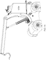
- FIG. 3 shows a side perspective view of the device of FIG. 1 , configured as a jib hoist.
- FIG. 4 shows a top perspective view of the rolling transportation cart embodiment.
- FIG. 5 shows a top and side perspective view of the jib hoist embodiment.
- FIG. 6 shows the jib hoist embodiment with parts shown schematically.
- FIG. 7 shows the rolling transportation cart embodiment with parts shown schematically.
- FIG. 8 shows the wider jib hoist wheel and drivetrain.
- FIG. 9 shows the narrower rolling transportation cart wheel and partially embedded drivetrain.
- FIG. 10 shows how the drivetrain is partially embedded into the wheel.
- FIG. 11 shows how the drivetrain is partially embedded into the wheel.
- FIG. 12 shows a front and side perspective view of the jib hoist embodiment, with the jib rail in the down position.
- FIG. 13 shows an operator using the tethered pendant controller to operate the jib hoist.
- FIG. 14 shows a side view of the jib hoist with the jib rail partially raised.
- FIG. 15 shows a view of the jib hoist with the hook in its maximum height position.
- FIG. 1 a block diagram of the parts of the mobile omnidirectional device is shown generally at 10 .
- the wheels can be any type of wheel, but preferably for the zero turning radius feature are Mecannum wheels which are pivotally mounted to provide continuous contact of all 4 wheels with the ground. A crossed roller bearing is used to support the pivot mount.
- the drive motor is semi-embedded into the Mecannum wheel, and while any drive motor can be utilized, preferably a custom frameless servo is used.
- the wheels and drive motors are connected to a base support, discussed further below.
- Power to drive the motors and wheels is provided at 28 , and as described in more detail below, is preferably four 12 volt batteries with an included recharger.
- the controller which operates the mobile omnidirectional device is shown at 30 , and can be operated with a tethered pendant controller or a wireless remote control device. In the preferred embodiment the operator walks behind the device using the wired tethered pendant controller to operate the device.
- FIG. 2 shows a side perspective view of the device of FIG. 1 , configured as a rolling transportation cart. Because the rolling transportation cart is only 2 feet wide, a narrower Mecannum wheel is used than for the jib hoist embodiment discussed below in connection with FIG. 3 .
- the base support is shown at 32 , and support the components of the device, such as the wheels, motors, batteries and so forth.
- a height adjustable frame 34 is attached to the device, and a pair of lift actuators are provided for lifting the frame 34 from a height of 18 to 24 inches, although any desired height could be provided. Alignment couplers attached to the lift actuators also permit the end to end height to be adjusted by up to 1 ⁇ 2 inch to maintain a level platform, which is attached to the frame (not shown in FIG. 2 .
- FIG. 3 shows a side perspective view of the device of FIG. 1 , configured as a jib hoist.
- the jib hoist embodiment provides a lift motor 36 , which can be any commercially available lift motor, but preferably a Kollmorgen servo is used.
- the lift motor 36 drives a lift actuator 38 , which can be any commercially available lift actuator, but is preferably a Tolomatic roller screw device.
- the lift actuator 38 is connected to the jib rail 40 , which is pivotally connected to a jib column 42 .
- the jib hoist is operated by the tethered pendant controller 44 , which drives the device and operates the jib hoist.
- a set of four handles 46 are attached to the device 10 to lift the device for portability purposes.
- the jib hoist configured device is sized to be portable, having a width of approximately 38.5 inches, a length of approximately 58 inches and a height of approximately 50 inches, and weighs approximately 1750 pounds. With the jib rail in the down position, the device is about 50 inches high, and with the jib rail in the maximum up position, the maximum hook height is approximately 78 inches high.
- FIG. 4 shows a top perspective view of the rolling transportation cart embodiment, which the batteries arranged on the base support at 48 , 50 , 52 and 54 .
- the four 12 volt batteries provide 48 VDC and can operate the device continuously for at least 4 hour minimum, before needing to be recharged via recharger 56 .
- Servo motors 12 , 16 , 20 and 24 are narrower, and together with the narrower wheels allow the rolling transportation cart embodiment to have a width of 24 inches or less.
- FIG. 5 shows a top and side perspective view of the jib hoist embodiment.
- the batteries 48 , 50 , 52 and 54 are stacked at the back end of the device.
- FIG. 6 shows the jib hoist embodiment with parts shown schematically. 55 shows the crossed pivot roller bearing.
- FIG. 7 shows the rolling transportation cart embodiment with parts shown schematically.
- 55 is the crossed pivot roller bearing.
- 58 is the gearbox and 59 is the drivetrain hub.
- FIG. 8 shows the a jib hoist wheel 14 , which is a two roller wide version of the Mecannum wheel, the gearbox 58 and the drive motor 12 .
- FIG. 9 shows a rolling transportation wheel 14 , which is a single roller wide version of the Mecannum wheel and the custom frameless servo motor 12 .
- FIG. 10 shows how the drivetrain is partially embedded into the wheel.
- the crossed roller bearing is shown at 55
- the drivetrain hub is shown at 59
- the frameless servo motor is shown at 12 .
- the crossed roller bearing and drivetrain are partially embedded in the wheel 14 .
- FIG. 11 shows how the drivetrain is partially embedded into the wheel.
- the drivetrain hub is shown at 59
- the gearbox is shown at 58
- the servo motor is shown at 12 .
- FIG. 12 shows a front and side perspective view of the jib hoist embodiment, with the jib rail in the partially down position.
- FIG. 13 shows an operator using the tethered pendant controller to operate the jib hoist.
- FIG. 14 shows a side view of the jib hoist with the jib rail partially raised.
- FIG. 15 shows a view of the jib hoist with the hook in its maximum height position.
- any dependent claim which follows should be taken as alternatively written in a multiple dependent form from all prior claims which possess all antecedents referenced in such dependent claim if such multiple dependent format is an accepted format within the jurisdiction (e.g. each claim depending directly from claim 1 should be alternatively taken as depending from all previous claims).
- each claim depending directly from claim 1 should be alternatively taken as depending from all previous claims.
- the following dependent claims should each be also taken as alternatively written in each singly dependent claim format which creates a dependency from a prior antecedent-possessing claim other than the specific claim listed in such dependent claim below.
Abstract
Description
Claims (19)
Priority Applications (1)
| Application Number | Priority Date | Filing Date | Title |
|---|---|---|---|
| US16/684,821 US11541742B2 (en) | 2018-11-16 | 2019-11-15 | Mobile omnidirectional device |
Applications Claiming Priority (2)
| Application Number | Priority Date | Filing Date | Title |
|---|---|---|---|
| US201862768333P | 2018-11-16 | 2018-11-16 | |
| US16/684,821 US11541742B2 (en) | 2018-11-16 | 2019-11-15 | Mobile omnidirectional device |
Publications (2)
| Publication Number | Publication Date |
|---|---|
| US20200156459A1 US20200156459A1 (en) | 2020-05-21 |
| US11541742B2 true US11541742B2 (en) | 2023-01-03 |
Family
ID=70728750
Family Applications (1)
| Application Number | Title | Priority Date | Filing Date |
|---|---|---|---|
| US16/684,821 Active 2041-04-12 US11541742B2 (en) | 2018-11-16 | 2019-11-15 | Mobile omnidirectional device |
Country Status (1)
| Country | Link |
|---|---|
| US (1) | US11541742B2 (en) |
Families Citing this family (8)
| Publication number | Priority date | Publication date | Assignee | Title |
|---|---|---|---|---|
| JP2018131068A (en) * | 2017-02-15 | 2018-08-23 | ナブテスコ株式会社 | Drive device for transport dolly |
| CN210302393U (en) * | 2019-06-28 | 2020-04-14 | 汕头市益尔乐玩具有限公司 | Eccentric omnidirectional wheel |
| US11220175B2 (en) * | 2020-04-11 | 2022-01-11 | Rotao Tech Ltd | Low-unsprung-mass near-wheel IPASS system |
| CN112810383A (en) * | 2021-02-22 | 2021-05-18 | 一汽解放青岛汽车有限公司 | Automobile chassis with variable driving form and control method thereof |
| EP4347447A2 (en) * | 2021-05-26 | 2024-04-10 | Symbotic, Llc | Autonomous transport vehicle |
| FR3125521A1 (en) * | 2021-07-20 | 2023-01-27 | Manitou Bf | Work machine comprising battery elements |
| WO2023001621A1 (en) * | 2021-07-20 | 2023-01-26 | Manitou Bf | On-site vehicle comprising battery elements |
| KR102595302B1 (en) * | 2023-07-24 | 2023-10-30 | 임해진 | omnidirectional driving apparatus |
Citations (13)
| Publication number | Priority date | Publication date | Assignee | Title |
|---|---|---|---|---|
| US4718564A (en) | 1986-08-13 | 1988-01-12 | Bailey Jonathan L | Portable construction hoist |
| US20080211432A1 (en) * | 2005-07-21 | 2008-09-04 | Vasily Vasilievich Shkondin | All Wheel Drive Vehicle |
| US20080217277A1 (en) | 2005-12-12 | 2008-09-11 | Michael Spitsbergen | Portable hoist assembly mounting systems and methods |
| US20100206647A1 (en) * | 2009-02-13 | 2010-08-19 | Kanzaki Kokyukoki Mfg. Co., Ltd. | Riding work vehicle |
| US20130257373A1 (en) * | 2012-03-12 | 2013-10-03 | John M. Mallon, IV | Cable handling system |
| US9052165B1 (en) * | 2011-07-08 | 2015-06-09 | Christopher Rogers | Remotely operated robotic platform |
| US20180093708A1 (en) * | 2016-10-03 | 2018-04-05 | Agco Corporation | Steering axle for self-propelled windrower |
| US20180099555A1 (en) * | 2016-06-04 | 2018-04-12 | Chun-Hsiang Yang | Universal wheel |
| US20180192580A1 (en) * | 2017-01-12 | 2018-07-12 | Briggs & Stratton Corporation | Zero turn radius mower controls |
| US20180264956A1 (en) * | 2017-03-17 | 2018-09-20 | Toyota Jidosha Kabushiki Kaisha | Charge control device for in-vehicle battery |
| US20190193784A1 (en) * | 2017-12-21 | 2019-06-27 | Disney Enterprises, Inc. | Non-scrubbing vertical drive unit for a trackless or free roaming vehicle with zero turn radius |
| US10358040B1 (en) * | 2015-06-01 | 2019-07-23 | Hydro-Gear Limited Partnership | Drive assembly and system for utility vehicle |
| US10391854B1 (en) * | 2015-06-15 | 2019-08-27 | Hydro-Gear Limited Partnership | Drive and cooling system for utility vehicle |
-
2019
- 2019-11-15 US US16/684,821 patent/US11541742B2/en active Active
Patent Citations (14)
| Publication number | Priority date | Publication date | Assignee | Title |
|---|---|---|---|---|
| US4718564A (en) | 1986-08-13 | 1988-01-12 | Bailey Jonathan L | Portable construction hoist |
| US20080211432A1 (en) * | 2005-07-21 | 2008-09-04 | Vasily Vasilievich Shkondin | All Wheel Drive Vehicle |
| US7468587B2 (en) * | 2005-07-21 | 2008-12-23 | Ultra Motor Company Limited | All wheel drive vehicle |
| US20080217277A1 (en) | 2005-12-12 | 2008-09-11 | Michael Spitsbergen | Portable hoist assembly mounting systems and methods |
| US20100206647A1 (en) * | 2009-02-13 | 2010-08-19 | Kanzaki Kokyukoki Mfg. Co., Ltd. | Riding work vehicle |
| US9052165B1 (en) * | 2011-07-08 | 2015-06-09 | Christopher Rogers | Remotely operated robotic platform |
| US20130257373A1 (en) * | 2012-03-12 | 2013-10-03 | John M. Mallon, IV | Cable handling system |
| US10358040B1 (en) * | 2015-06-01 | 2019-07-23 | Hydro-Gear Limited Partnership | Drive assembly and system for utility vehicle |
| US10391854B1 (en) * | 2015-06-15 | 2019-08-27 | Hydro-Gear Limited Partnership | Drive and cooling system for utility vehicle |
| US20180099555A1 (en) * | 2016-06-04 | 2018-04-12 | Chun-Hsiang Yang | Universal wheel |
| US20180093708A1 (en) * | 2016-10-03 | 2018-04-05 | Agco Corporation | Steering axle for self-propelled windrower |
| US20180192580A1 (en) * | 2017-01-12 | 2018-07-12 | Briggs & Stratton Corporation | Zero turn radius mower controls |
| US20180264956A1 (en) * | 2017-03-17 | 2018-09-20 | Toyota Jidosha Kabushiki Kaisha | Charge control device for in-vehicle battery |
| US20190193784A1 (en) * | 2017-12-21 | 2019-06-27 | Disney Enterprises, Inc. | Non-scrubbing vertical drive unit for a trackless or free roaming vehicle with zero turn radius |
Also Published As
| Publication number | Publication date |
|---|---|
| US20200156459A1 (en) | 2020-05-21 |
Similar Documents
| Publication | Publication Date | Title |
|---|---|---|
| US11541742B2 (en) | Mobile omnidirectional device | |
| US10179617B2 (en) | Driven load-bearing system | |
| US11584181B2 (en) | Self leveling autonomous guided vehicle | |
| US20140299417A1 (en) | Lifting apparatus | |
| KR101707202B1 (en) | Automatic Transfer Vehicle | |
| US20180317368A1 (en) | Self-Moving Device and Control Method for Self-Moving Device | |
| CN110092325B (en) | Materials handling vehicle | |
| CN105152036A (en) | Electric transportation trolley for automatic glass mounting | |
| CN104108411A (en) | Self-propel Accessory | |
| CN205634803U (en) | Portable loader transporter | |
| CN204184402U (en) | There is the walking ladder truck of lifting mechanism | |
| US11787674B2 (en) | Mobility base | |
| US20240083717A1 (en) | Zero-gravity hoist control | |
| CN104591029B (en) | Mobile lifting device | |
| CN110092321B (en) | Material handling vehicle | |
| US9227737B2 (en) | Helicopter tug system | |
| EP3214034A1 (en) | Compact ergonomic self-propelled lifting machine | |
| KR101932596B1 (en) | Low floor boardable high place operation car | |
| US9718307B2 (en) | Tire handler | |
| CN216444898U (en) | Automatically controlled all direction movement formula portal crane device | |
| CN206456458U (en) | A kind of Automatic Guided Vehicle with hollow hydraulic jacking rotating mechanism | |
| KR101754205B1 (en) | Remote trailer robot | |
| CN218195158U (en) | Transfer robot | |
| CN110775832A (en) | A haulage equipment for in factory building | |
| CN210620138U (en) | Light-duty transport mechanical equipment |
Legal Events
| Date | Code | Title | Description |
|---|---|---|---|
| FEPP | Fee payment procedure |
Free format text: ENTITY STATUS SET TO UNDISCOUNTED (ORIGINAL EVENT CODE: BIG.); ENTITY STATUS OF PATENT OWNER: SMALL ENTITY |
|
| FEPP | Fee payment procedure |
Free format text: ENTITY STATUS SET TO SMALL (ORIGINAL EVENT CODE: SMAL); ENTITY STATUS OF PATENT OWNER: SMALL ENTITY |
|
| STPP | Information on status: patent application and granting procedure in general |
Free format text: APPLICATION DISPATCHED FROM PREEXAM, NOT YET DOCKETED |
|
| STPP | Information on status: patent application and granting procedure in general |
Free format text: DOCKETED NEW CASE - READY FOR EXAMINATION |
|
| STPP | Information on status: patent application and granting procedure in general |
Free format text: NON FINAL ACTION MAILED |
|
| STPP | Information on status: patent application and granting procedure in general |
Free format text: RESPONSE TO NON-FINAL OFFICE ACTION ENTERED AND FORWARDED TO EXAMINER |
|
| STPP | Information on status: patent application and granting procedure in general |
Free format text: FINAL REJECTION MAILED |
|
| STPP | Information on status: patent application and granting procedure in general |
Free format text: RESPONSE AFTER FINAL ACTION FORWARDED TO EXAMINER |
|
| STPP | Information on status: patent application and granting procedure in general |
Free format text: NOTICE OF ALLOWANCE MAILED -- APPLICATION RECEIVED IN OFFICE OF PUBLICATIONS |
|
| STPP | Information on status: patent application and granting procedure in general |
Free format text: PUBLICATIONS -- ISSUE FEE PAYMENT RECEIVED |
|
| STCF | Information on status: patent grant |
Free format text: PATENTED CASE |