EP4309937B1 - Arbeitsmaschine mit einer seitlich angeordneten kabine und einem unter der kabine befestigten batteriemodul - Google Patents
Arbeitsmaschine mit einer seitlich angeordneten kabine und einem unter der kabine befestigten batteriemodul Download PDFInfo
- Publication number
- EP4309937B1 EP4309937B1 EP23184285.7A EP23184285A EP4309937B1 EP 4309937 B1 EP4309937 B1 EP 4309937B1 EP 23184285 A EP23184285 A EP 23184285A EP 4309937 B1 EP4309937 B1 EP 4309937B1
- Authority
- EP
- European Patent Office
- Prior art keywords
- construction vehicle
- battery module
- fastening
- cab
- battery
- Prior art date
- Legal status (The legal status is an assumption and is not a legal conclusion. Google has not performed a legal analysis and makes no representation as to the accuracy of the status listed.)
- Active
Links
Images







Classifications
-
- B—PERFORMING OPERATIONS; TRANSPORTING
- B60—VEHICLES IN GENERAL
- B60K—ARRANGEMENT OR MOUNTING OF PROPULSION UNITS OR OF TRANSMISSIONS IN VEHICLES; ARRANGEMENT OR MOUNTING OF PLURAL DIVERSE PRIME-MOVERS IN VEHICLES; AUXILIARY DRIVES FOR VEHICLES; INSTRUMENTATION OR DASHBOARDS FOR VEHICLES; ARRANGEMENTS IN CONNECTION WITH COOLING, AIR INTAKE, GAS EXHAUST OR FUEL SUPPLY OF PROPULSION UNITS IN VEHICLES
- B60K1/00—Arrangement or mounting of electrical propulsion units
- B60K1/04—Arrangement or mounting of electrical propulsion units of the electric storage means for propulsion
-
- B—PERFORMING OPERATIONS; TRANSPORTING
- B66—HOISTING; LIFTING; HAULING
- B66F—HOISTING, LIFTING, HAULING OR PUSHING, NOT OTHERWISE PROVIDED FOR, e.g. DEVICES WHICH APPLY A LIFTING OR PUSHING FORCE DIRECTLY TO THE SURFACE OF A LOAD
- B66F9/00—Devices for lifting or lowering bulky or heavy goods for loading or unloading purposes
- B66F9/06—Devices for lifting or lowering bulky or heavy goods for loading or unloading purposes movable, with their loads, on wheels or the like, e.g. fork-lift trucks
- B66F9/075—Constructional features or details
- B66F9/07513—Details concerning the chassis
- B66F9/07531—Battery compartments
-
- B—PERFORMING OPERATIONS; TRANSPORTING
- B66—HOISTING; LIFTING; HAULING
- B66F—HOISTING, LIFTING, HAULING OR PUSHING, NOT OTHERWISE PROVIDED FOR, e.g. DEVICES WHICH APPLY A LIFTING OR PUSHING FORCE DIRECTLY TO THE SURFACE OF A LOAD
- B66F9/00—Devices for lifting or lowering bulky or heavy goods for loading or unloading purposes
- B66F9/06—Devices for lifting or lowering bulky or heavy goods for loading or unloading purposes movable, with their loads, on wheels or the like, e.g. fork-lift trucks
- B66F9/075—Constructional features or details
- B66F9/12—Platforms; Forks; Other load supporting or gripping members
-
- B—PERFORMING OPERATIONS; TRANSPORTING
- B60—VEHICLES IN GENERAL
- B60K—ARRANGEMENT OR MOUNTING OF PROPULSION UNITS OR OF TRANSMISSIONS IN VEHICLES; ARRANGEMENT OR MOUNTING OF PLURAL DIVERSE PRIME-MOVERS IN VEHICLES; AUXILIARY DRIVES FOR VEHICLES; INSTRUMENTATION OR DASHBOARDS FOR VEHICLES; ARRANGEMENTS IN CONNECTION WITH COOLING, AIR INTAKE, GAS EXHAUST OR FUEL SUPPLY OF PROPULSION UNITS IN VEHICLES
- B60K1/00—Arrangement or mounting of electrical propulsion units
- B60K1/04—Arrangement or mounting of electrical propulsion units of the electric storage means for propulsion
- B60K2001/0405—Arrangement or mounting of electrical propulsion units of the electric storage means for propulsion characterised by their position
- B60K2001/0438—Arrangement under the floor
-
- B—PERFORMING OPERATIONS; TRANSPORTING
- B60—VEHICLES IN GENERAL
- B60K—ARRANGEMENT OR MOUNTING OF PROPULSION UNITS OR OF TRANSMISSIONS IN VEHICLES; ARRANGEMENT OR MOUNTING OF PLURAL DIVERSE PRIME-MOVERS IN VEHICLES; AUXILIARY DRIVES FOR VEHICLES; INSTRUMENTATION OR DASHBOARDS FOR VEHICLES; ARRANGEMENTS IN CONNECTION WITH COOLING, AIR INTAKE, GAS EXHAUST OR FUEL SUPPLY OF PROPULSION UNITS IN VEHICLES
- B60K1/00—Arrangement or mounting of electrical propulsion units
- B60K1/04—Arrangement or mounting of electrical propulsion units of the electric storage means for propulsion
- B60K2001/0455—Removal or replacement of the energy storages
-
- B—PERFORMING OPERATIONS; TRANSPORTING
- B60—VEHICLES IN GENERAL
- B60K—ARRANGEMENT OR MOUNTING OF PROPULSION UNITS OR OF TRANSMISSIONS IN VEHICLES; ARRANGEMENT OR MOUNTING OF PLURAL DIVERSE PRIME-MOVERS IN VEHICLES; AUXILIARY DRIVES FOR VEHICLES; INSTRUMENTATION OR DASHBOARDS FOR VEHICLES; ARRANGEMENTS IN CONNECTION WITH COOLING, AIR INTAKE, GAS EXHAUST OR FUEL SUPPLY OF PROPULSION UNITS IN VEHICLES
- B60K1/00—Arrangement or mounting of electrical propulsion units
- B60K1/04—Arrangement or mounting of electrical propulsion units of the electric storage means for propulsion
- B60K2001/0455—Removal or replacement of the energy storages
- B60K2001/0461—Removal or replacement of the energy storages from the side
-
- B—PERFORMING OPERATIONS; TRANSPORTING
- B60—VEHICLES IN GENERAL
- B60L—PROPULSION OF ELECTRICALLY-PROPELLED VEHICLES; SUPPLYING ELECTRIC POWER FOR AUXILIARY EQUIPMENT OF ELECTRICALLY-PROPELLED VEHICLES; ELECTRODYNAMIC BRAKE SYSTEMS FOR VEHICLES IN GENERAL; MAGNETIC SUSPENSION OR LEVITATION FOR VEHICLES; MONITORING OPERATING VARIABLES OF ELECTRICALLY-PROPELLED VEHICLES; ELECTRIC SAFETY DEVICES FOR ELECTRICALLY-PROPELLED VEHICLES
- B60L2200/00—Type of vehicles
- B60L2200/40—Working vehicles
-
- B—PERFORMING OPERATIONS; TRANSPORTING
- B60—VEHICLES IN GENERAL
- B60Y—INDEXING SCHEME RELATING TO ASPECTS CROSS-CUTTING VEHICLE TECHNOLOGY
- B60Y2200/00—Type of vehicle
- B60Y2200/40—Special vehicles
-
- B—PERFORMING OPERATIONS; TRANSPORTING
- B60—VEHICLES IN GENERAL
- B60Y—INDEXING SCHEME RELATING TO ASPECTS CROSS-CUTTING VEHICLE TECHNOLOGY
- B60Y2200/00—Type of vehicle
- B60Y2200/40—Special vehicles
- B60Y2200/41—Construction vehicles, e.g. graders, excavators
-
- B—PERFORMING OPERATIONS; TRANSPORTING
- B60—VEHICLES IN GENERAL
- B60Y—INDEXING SCHEME RELATING TO ASPECTS CROSS-CUTTING VEHICLE TECHNOLOGY
- B60Y2200/00—Type of vehicle
- B60Y2200/40—Special vehicles
- B60Y2200/41—Construction vehicles, e.g. graders, excavators
- B60Y2200/412—Excavators
Definitions
- the invention relates to a work machine comprising a lifting arm and a battery module for providing electrical power to the work machine.
- a work machine comprising a mobile chassis movable on the ground surface, the chassis comprising two side members parallel to each other and extending parallel to a front-rear axis of the machine, and a lifting arm, the lifting arm being mounted between the two side members so as to be pivotally movable relative to the two side members.
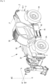
- the machine 1 comprises a cabin 29 in which a driver of the machine 1 can sit, and a box 28 capable of receiving various equipment of the machine 1.
- the cabin 29 projects from the spar 10-1 in a direction opposite to the spar 10-2 and the box 28 projects from the spar 10-2 in a direction opposite to the spar 10-1.
- the box 28 is arranged along the spar 10-2, externally to this spar 10-2 in the transverse direction BB.
- BB transverse direction
- the cabin 29 and the box 28 are arranged between the front axle 3 and the rear axle 4 in the longitudinal direction A-A.
- a battery module 40 is arranged under the cabin 29 in the vertical direction CC.
- the battery module 40 is intended to supply electricity to at least one electric motor of the machine 1 as will be described below.
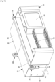
- the battery module 40 will now be described with reference to: Figures 4A , 4B , 4C , 4D And 5 .
- the battery module 40 is generally parallelepipedal and comprises a receiving structure 41.
- the receiving structure 41 comprises a bottom plate 42, a top plate 46 parallel to the bottom plate 42, and side plates 45 extending perpendicular to the top plate 46 and the bottom plate 42, such that the bottom plate 42, the top plate 46 and the side plates 45 together define a receiving volume for battery cells 60.
- At least two 60 battery cells rest on an upper face (i.e. facing upwards in the vertical direction CC) of the bottom plate 42.
- the receiving structure 41 may comprise one or more intermediate support elements 43 (cf. Figure 4A And Figure 4B ), planes and parallel to the bottom plate 42, and other battery elements 60 rest on this or these intermediate support elements 43.
- Separator plates 44 may extend perpendicular to the bottom plate 42 and the intermediate support elements 43, so as to define sub-volumes, each of the sub-volumes being sized for receiving a battery element 60.
- each battery element 60 comprises a parallelepiped housing enclosing the electrolytic cell(s) generating the voltage at the terminals of the battery element 60.
- the battery element 60 is for example of the lithium-ion or other type.
- one of the faces of the housing carries a battery management system (“Battery Management System” or BMS in English) which, still in a manner known per se, monitors and manages the charging and discharging of all the electrolytic cells of the battery element 60.
- This battery management system also carries the output terminals of the battery element 60.
- the battery management system can be shared between several battery elements 60 and/or integrated into the connection box 50 described below.
- a battery element 60 is received in each sub-volume defined by the bottom plate 42, the intermediate support elements 43 and the separation plates 44.
- Each battery element 60 is held in place by means of removable fixing elements 69 (cf. Figure 4B ), such as screws, which are received in blind holes 69B presented by the separation plates 44 (cf. Figures 4A And 4B ).
- the removable fastening elements 69 are electrically conductive and the separation plates 44 are electrically conductive, the separation plates 44 are electrically connected to each other and to the battery cells 60 so as to constitute a common electrical ground for the battery cells 60. It is thus possible to ground all the battery cells 60 in a very simple manner, without additional wiring.
- the removable fastening elements 69 and the separation plates 44 are made electrically conductive by a galvanizing process, in particular by electrogalvanizing. Electrogalvanizing is particularly advantageous because it also makes it possible to protect the separation plates 44 (and possibly other elements of the receiving structure 41) against corrosion.
- the battery elements 60 are electrically connected to at least one electrical connection box 50.
- the battery module 40 comprises twelve battery cells 60, and each battery cell 60 outputs a voltage of 48 V.
- the battery cells 60 are connected in series in pairs to each output a voltage of 96 V.
- Three pairs of battery cells 60 are connected in parallel with each other to a first connection box 50 by means of electric cables 99, and three other pairs of battery cells 60 are connected in parallel with each other to a second connection box 50 by means of electric cables 99.
- Each connection box 50 comprises a power output socket 51 allowing the electrical connection of the battery module 40 to a power input socket 400 (cf. figure 5 ) of the device 1.
- the machine 1 comprises a power distribution box 410 which carries the power input sockets 400 and which is configured to supply or not the electrical components of the machine 1.
- a power distribution box 410 which carries the power input sockets 400 and which is configured to supply or not the electrical components of the machine 1.
- Such power distribution boxes are known as such and are not described in detail here.
- the power distribution box 410 is in particular electrically connected to an 80V electric speed variator itself electrically connected to an electric motor 80 for the propulsion of the chassis 2, and to an 87V electric speed variator itself electrically connected to an electric motor 87 for the actuation of the lifting arm 20.
- the 80V and 87V electric speed variators are here of the three-phase inverter type, that is to say receiving a direct voltage as input and providing a three-phase alternating voltage as output. Other electrical configurations are however possible.
- the power distribution box 410 can further be electrically connected to other electrical equipment of the machine 1, in particular a cabin heating module 29, and/or a cabin air conditioning module 29, and/or one or more direct-direct (DC/DC) converters for the electrical supply of other electrical equipment of the machine, for example a signal light, an audible warning device, etc.
- DC/DC direct-direct
- the power distribution box 410 can for example be received in the box 28.
- the electrical connection boxes 50 can be arranged under the cabin 29 due to their positioning on the battery module 40.
- the battery module 40 further comprises a fixing structure generally designated by 70.
- the fixing portions 79 are attached, for example by bolting, to wings 78.
- the wings 78 are secured to the holding frame 72, for example by welding.
- the power distribution box 410 may include a charging socket 490 for recharging the battery elements 60.
- the hatch 92 it is preferable for the hatch 92 also to allow access to a compartment sized to contain a charging cable electrically connectable to this charging socket 490.
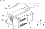
- the fixing arm 110 comprises a yoke 111.
- the yoke 111 consists of two cheeks 112, 113.
- the cheeks 112, 113 are parallel to each other and spaced apart from each other in the transverse direction B-B.
- the cheeks 112, 113 have aligned through holes 112F, 113F.
- the fixing arm 120 comprises a yoke 121.
- the yoke 121 consists of two cheeks 122, 123.
- the cheeks 122, 123 are parallel to each other and spaced from each other in the transverse direction BB.
- the cheeks 122, 123 have aligned through holes 122F, 123F.
- the battery module 40 is first made to describe a translational movement D parallel to the transverse direction BB, to bring the battery module 40 to the position shown in the figure.
- Figure 7A the fixing portions 79 are in contact with sliding surfaces 113A, 123A (cf. Figure 6 and Figure 7A ) which are respectively presented by cheeks 113 and 123 and which extend in the vertical direction CC and the longitudinal direction AA.
- the battery module 40 is made to describe a translational movement E parallel to the vertical direction CC, to bring the battery module 40 to the position shown in the figure.
- Figure 7B This translational movement E is guided by the sliding of the fixing portions 79 and the sliding surfaces 113A, 123A.
- the fixing portions 79 are engaged in the yokes 111, 121, and the hollow cylinders 79F are aligned with the through holes 112F, 113F, 122F, 123F.
- the fixing portions 79 may be provided with elastic supports 79A, for example made of rubber or polymer, engaged on the cylinders 79F. These elastic supports 79A may furthermore dampen vibrations due to the operation of the machine 1 and thus protect the battery module 40 against these vibrations.
- the attachment which has just been described of the battery module 40 is easily removable since it suffices to remove the pins 390 and to carry out the steps described above in the reverse order to remove the battery module 40 from under the cabin 29. It is therefore easy to replace the battery module 40 when desired, for example to replace a discharged battery module 40 with a charged battery module 40.
- the battery module 40 could be secured by screwing or bolting the mounting portions 79 to the yokes 111, 121.
- the battery module 40 may be sized so as to extend partly under a space located between the side members 10-1, 10-2. This may make it possible to increase the volume of the battery cells 60 and therefore the total load capacity of the battery module 40. This may further make it possible to improve the lateral balance of the vehicle 1 since the center of mass of the battery module 40 is closer to the centerline of the vehicle 1.
- the side member 10-1 has a cutout 590 (cf. figures 6 to 8 ) to allow the passage of the battery module 40.
- the additional fastening arm 130 extends between the longitudinal members 10-1, 10-2. As can be seen in the figures, the additional fastening arm 130 is analogous to the fastening arms 110, 120, and the additional fastening portion 89 is analogous to the fastening portions 79. Their cooperation is thus analogous to the already described cooperation of the fastening portions 79 with the fastening arms 110, 120, and is therefore not described in detail again for the sake of brevity.
- the fixing arm 110 supports the cabin 29.
- the fixing arm 110 has a surface 118 for supporting the cabin 29.
- the fixing arm 110 may further have a through hole 119 for receiving a resilient support (not shown) disposed between the cabin 29 and the fixing arm 110.
- the fixing arm 110 and the fixing arm 120 may both support the cabin 29.
- the fixing arm 120 may support the cabin 29 and not the fixing arm 110.
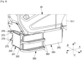
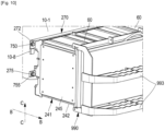
- a battery module 240 is provided to be fixed directly to the spar 10-1, in a fixing position which is located under the cabin 29 in the vertical direction CC.
- the battery module 240 is generally parallelepiped and comprises a receiving structure 241 and a fixing structure 270.
- the receiving structure 241 is in the form of a parallelepiped box which defines a receiving volume for battery elements 60.
- the receiving structure 241 thus comprises a bottom plate 242, and side plates 245 extending perpendicular to the bottom plate 242.
- At least two battery cells 60 rest on an upper face (i.e. facing upwards in the vertical direction C-C) of the bottom plate 242.
- the receiving structure 241 may comprise one or more intermediate support elements (not shown), planar and parallel to the bottom plate 242, and other battery cells 60 rest on this or these intermediate support elements.
- the fixing structure 270 comprises a profiled element 272.
- the profiled element 272 is secured to the receiving structure 241, preferably by spot welding.
- the profiled element 272 is here in the form of an angle iron having an “L”-shaped section and extends along the entire length of the receiving structure 241.
- the profiled element 272 has, at each of its two ends, a through hole 276 (cf. figure 9 ) sized to receive a removable 750 fixing element (cf. figure 10 ) such as a bolt or screw.
- the removable fastening element 750 allows the profiled element 272 and thereby the battery module 240 to be fixed directly to the spar 10-1 by means of corresponding blind holes (not shown) made in the spar 10-1.
- the battery module 240 can be brought under the cabin 29 in the position shown in the figure 9 and the figure 10 , by a simple translational movement parallel to the transverse direction BB.
- a battery module 340 is provided to be indirectly attached to the spar 10-1, in a fixing position which is located under the cabin 29 in the vertical direction CC.
- Elements identical to those already described previously bear the same reference signs and are not described again except when necessary.
Landscapes
- Engineering & Computer Science (AREA)
- Transportation (AREA)
- Structural Engineering (AREA)
- Mechanical Engineering (AREA)
- Civil Engineering (AREA)
- Life Sciences & Earth Sciences (AREA)
- Geology (AREA)
- Chemical & Material Sciences (AREA)
- Combustion & Propulsion (AREA)
- Battery Mounting, Suspending (AREA)
- Arrangement Or Mounting Of Propulsion Units For Vehicles (AREA)
Claims (16)
- Arbeitsmaschine (1), umfassend:- ein Chassis (2) mit einem ersten Längsträger (10-1) und einem zweiten Längsträger (20-2), wobei der erste Längsträger (10-1) und der zweite Längsträger (10-2) zueinander parallel sind und sich in einer Längsrichtung (A-A) der Arbeitsmaschine (1) parallel erstrecken; und mit einer Vorderachse (3) und einer Hinterachse (4), die entlang der Längsrichtung (A-A) der Arbeitsmaschine (1) voneinander beabstandet sind;- einen Hebearm (20), der sich parallel zur Längsrichtung (A-A) der Arbeitsmaschine (1) erstreckt, wobei der Hebearm (20) zwischen den beiden Längsträgeren derart an den beiden Längsträgeren angelenkt ist, dass er in Bezug auf die Längsträger (10-1, 10-2) um eine Schwenkachse (P-P), die sich entlang einer zur Längsrichtung (A-A) der Arbeitsmaschine (1) senkrechten Querrichtung (B-B) der Arbeitsmaschine (1) erstreckt, schwenkbeweglich ist;- mindestens einen Elektromotor (80, 87) für den Vortrieb des Chassis (2) und optional für die Betätigung des Hebearms (20);- eine Kabine (29) für die Bedienungsperson der Arbeitsmaschine (1), wobei die Kabine (29) von dem ersten Längsträger (10-2) entlang der Querrichtung (B-B) der Arbeitsmaschine (1) in eine zum zweiten Längsträger (10-2) entgegengesetzte Richtung vorspringt, wobei die Kabine (29) entlang der Längsrichtung (A-A) der Arbeitsmaschine (1) zwischen der Vorderachse (3) und der Hinterachse (4) angeordnet ist; undein Batteriemodul (40; 240; 340) zur Stromversorgung des mindestens einen Elektromotors (80, 98),dadurch gekennzeichnet, dassdas Batteriemodul (40; 240; 340) eine Befestigungskonstruktion aufweist, die ausgebildet ist zur abnehmbaren Befestigung an dem ersten Längsträger (10-1) in einer Befestigungsposition unter der Kabine (29) entlang einer zur Längsrichtung (A-A) und zur Querrichtung (B-B) der Arbeitsmaschine (1) senkrechten vertikalen Richtung (C-C) der Arbeitsmaschine (1), wobei das Batteriemodul (40; 240; 340) in der Befestigungsposition von einer Außenseite der Arbeitsmaschine (1) zugänglich ist, um in eine Befestigungsposition gebracht werden zu können und um von der Außenseite der Arbeitsmaschine (1) aus der Befestigungsposition entfernt werden zu können, wobei die Außenseite der Arbeitsmaschine (1) in die Querrichtung (B-B) der Arbeitsmaschine (1) gedreht wird.
- Arbeitsmaschine (1) nach Anspruch 1, wobei die Befestigungskonstruktion (270) ein Profilelement (272) umfasst, das an seinen beiden Enden abnehmbar, z.B. durch Bolzenverbindung oder Verschraubung, direkt an dem ersten Längsträger (10-1) befestigt ist.
- Arbeitsmaschine (1) nach Anspruch 2, wobei der erste Längsträger (10-1) mindestens ein Widerlager (10-8) aufweist, das sich entlang der vertikalen Richtung (C-C) der Arbeitsmaschine (1) unter dem Profilelement (272) befindet und auf dem das Profilelement (272) aufliegt, wenn es an dem ersten Längsträger (10-1) befestigt ist.
- Arbeitsmaschine (1) nach Anspruch 1, wobei die Arbeitsmaschine (1) ferner zwei Halteplatten (600) aufweist, die von dem ersten Längsträger (10-1) vorspringen, wobei sich die beiden Halteplatten (600) unter der Kabine (29) befinden und sich entlang der vertikalen Richtung (C-C) und der Querrichtung (B-B) der Arbeitsmaschine (1) erstrecken und entlang der Längsrichtung (A-A) der Arbeitsmaschine (1) voneinander beabstandet sind und wobei die Befestigungskonstruktion zwei Befestigungsplatten (245) umfasst, wovon jede Befestigungsplatte (245) zum Beispiel durch eine Bolzenverbindung oder Verschraubung an einer der Halteplatten (600) abnehmbar befestigt ist.
- Arbeitsmaschine (1) nach Anspruch 1, wobei das Batteriemodul (340) ferner zwei Führungselemente (390) aufweist, wobei jedes Führungselement (390) dazu bestimmt ist, mit einem oberen Ende einer der Halteplatten (600) derart zusammenzuwirken, dass das Batteriemodul (340) in einer Translationsbewegung parallel zur Querrichtung (B-B) der Arbeitsmaschine (1) in die Befestigungsposition geführt wird.
- Arbeitsmaschine (1) nach Anspruch 1, wobei:- die Arbeitsmaschine (1) ferner zwei Befestigungsarme (110, 120) hat, die von dem ersten Längsträger (10-1) vorspringen, wobei sich die beiden Befestigungsarme (110 120) entlang der Querrichtung (B-B) der Arbeitsmaschine (1) unter der Kabine (29) erstrecken und entlang der Längsrichtung (A-A) der Arbeitsmaschine (1) voneinander beabstandet sind.- die Befestigungskonstruktion (70) zwei Befestigungsbereiche (79) aufweist; und- jeder der Befestigungsarme (110, 120) einen Gabelkopf (111, 121) aufweist und jeder der Befestigungsbereiche (79) abnehmbar an einem der Gabelköpfe (111, 121) befestigt ist.
- Arbeitsmaschine (1) nach Anspruch 6, wobei mindestens einer der Gabelköpfe (111, 112) eine Gleitfläche (113A, 123A) hat, die sich entlang der vertikalen Richtung (C-C) und der Längsrichtung (A-A) der Arbeitsmaschine (1) erstreckt, und wobei mindestens einer der Befestigungsbereiche (79) dazu ausgebildet ist, in einer Translationsbewegung (E) parallel zur vertikalen Richtung (C-C) bis zur Befestigungsposition an der Gleitfläche (113A, 123A) zu gleiten.
- Arbeitsmaschine (1) nach Anspruch 7, wobei mindestens einer der Befestigungsbereiche (79) ein Gleitelement aus Polymer oder Kautschuk aufweist, um an der Gleitfläche (113A, 123A) zu gleiten.
- Arbeitsmaschine (1) nach einem der Ansprüche 6 bis 8, wobei sich das Batteriemodul (40) zum Teil bis unter einen zwischen den Längsträgern (10-1, 10-2) liegenden Raum erstreckt.
- Arbeitsmaschine (1) nach einem der Ansprüche 6 bis 9, wobei mindestens einer der beiden Befestigungsarme (110, 210) die Kabine (29) stützt.
- Arbeitsmaschine (1) nach einem der Ansprüche 1 bis 10, wobei ein Stromverteilerkasten (410) mit dem mindestens einen Elektromotor (80, 87) elektrisch verbunden ist und das Batteriemodul (40; 240; 340) eine einzige Stromausgangsbuchse (51) aufweist, die mit dem Stromverteilerkasten (410) elektrisch verbunden werden kann.
- Arbeitsmaschine (1) nach Anspruch 11, wobei das Batteriemodul (40 240; 340) umfasst:- eine Bodenplatte (42; 242), wobei die Befestigungskonstruktion (70; 270) fest mit der Bodenplatte (42; 242) verbunden ist oder diese stützt;- mindestens zwei Batterieelemente (60), die entlang der vertikalen Richtung auf einer Oberseite der Bodenplatte (42; 242) lasten;- mindestens einen elektrischen Anschlusskasten (50), der mit den Batterieelementen (60) elektrisch verbunden ist, wobei der elektrische Anschlusskasten (50) eine Stromausgangsbuchse (51) aufweist, die mit dem Stromverteilerkasten (410) elektrisch verbunden werden kann.
- Arbeitsmaschine (1) nach Anspruch 12, wobei das Batteriemodul (40; 240; 340) Trennplatten (44) aufweist, die die Batterieelemente (60) trennen und an denen die Batterieelemente (60) durch abnehmbare Befestigungselemente (69) befestigt sind, wobei die Befestigungselemente (69) und die Trennplatten (44) elektrisch leitend sind und die Trennplatten (44) elektrisch miteinander und mit den Batterieelementen (60) verbunden sind, um eine gemeinsame elektrische Masse der Batteriezellen (60) zu bilden.
- Arbeitsmaschine (1) nach einem der Ansprüche 11 bis 13, wobei der Stromverteilerkasten (410) eine Ladebuchse zum Aufladen der Batteriemodule (40; 240; 340) aufweist.
- Arbeitsmaschine (1) nach einem der Ansprüche 1 bis 14, wobei das Batteriemodul (40; 240; 340) ferner eine Verkleidung (90; 990) aufweist, die in der Befestigungsposition des Batteriemoduls (40; 240; 340) entlang der Querrichtung (B-B) zur Außenseite des Arbeitsgeräts (1) gerichtet ist, wobei die Verkleidung (90; 990) ein oder mehrere Trittbretter (93; 993) umfasst, das oder die der Bedienungsperson der Arbeitsmaschine (1) Zugang zur Kabine (29) ermöglicht bzw. ermöglichen.
- Arbeitsmaschine (1) nach Anspruch 15 in Verbindung mit Anspruch 14, ferner umfassend ein Ladekabel, wobei das Ladekabel mit der Ladebuchse (490) elektrisch verbindbar ist und wobei die Verkleidung (90; 990) eine Klappe (92; 992) aufweist, die Zugang zu einem Fach ermöglicht, das für die Aufnahme des Ladekabels dimensioniert ist.
Applications Claiming Priority (1)
| Application Number | Priority Date | Filing Date | Title |
|---|---|---|---|
| FR2207339A FR3137874B1 (fr) | 2022-07-18 | 2022-07-18 | Engin de travail avec une cabine située latéralement et un module de batteries fixé sous la cabine |
Publications (2)
| Publication Number | Publication Date |
|---|---|
| EP4309937A1 EP4309937A1 (de) | 2024-01-24 |
| EP4309937B1 true EP4309937B1 (de) | 2025-03-05 |
Family
ID=83505600
Family Applications (1)
| Application Number | Title | Priority Date | Filing Date |
|---|---|---|---|
| EP23184285.7A Active EP4309937B1 (de) | 2022-07-18 | 2023-07-07 | Arbeitsmaschine mit einer seitlich angeordneten kabine und einem unter der kabine befestigten batteriemodul |
Country Status (4)
| Country | Link |
|---|---|
| US (1) | US12565409B2 (de) |
| EP (1) | EP4309937B1 (de) |
| FR (1) | FR3137874B1 (de) |
| PL (1) | PL4309937T3 (de) |
Families Citing this family (5)
| Publication number | Priority date | Publication date | Assignee | Title |
|---|---|---|---|---|
| US20230415556A1 (en) * | 2022-06-28 | 2023-12-28 | Oshkosh Corporation | Unibody refuse vehicle |
| FR3137874B1 (fr) * | 2022-07-18 | 2024-05-31 | Manitou Bf | Engin de travail avec une cabine située latéralement et un module de batteries fixé sous la cabine |
| US20240240658A1 (en) * | 2023-01-17 | 2024-07-18 | Narendra Gupta | Hydraulic power pack module |
| JP7733036B2 (ja) * | 2023-02-27 | 2025-09-02 | 株式会社竹内製作所 | 作業用車両 |
| CN118026056B (zh) * | 2024-03-04 | 2025-12-19 | 浙江中力机械股份有限公司 | 一种可快速补电的锂电池叉车 |
Family Cites Families (20)
| Publication number | Priority date | Publication date | Assignee | Title |
|---|---|---|---|---|
| USD376243S (en) * | 1995-02-27 | 1996-12-03 | Manitou Bf | Lift truck |
| US6631775B1 (en) * | 2000-07-06 | 2003-10-14 | George T. Chaney | Electric vehicle chassis with removable battery module and a method for battery module replacement |
| US7520355B2 (en) * | 2000-07-06 | 2009-04-21 | Chaney George T | Hybrid electric vehicle chassis with removable battery module |
| JP2005262978A (ja) | 2004-03-17 | 2005-09-29 | Hitachi Constr Mach Co Ltd | 作業機械およびその製造方法 |
| DE102006031461A1 (de) * | 2006-07-07 | 2008-01-10 | Jungheinrich Aktiengesellschaft | Batteriewechselsystem für ein batteriebetriebenes Flurförderzeug |
| ITTO20100310A1 (it) * | 2010-04-16 | 2011-10-17 | Movimatica Srl | Veicolo sollevatore ibrido elettro-idraulico |
| KR101815331B1 (ko) * | 2010-06-15 | 2018-01-04 | 가부시키가이샤 히다치 겡키 티에라 | 전동식 건설 기계 |
| FR2990401B1 (fr) * | 2012-05-11 | 2014-04-25 | Manitou Bf | Dispositif de suspension de cabine de vehicule |
| FR3018797B1 (fr) * | 2014-03-19 | 2019-03-29 | Societe Des Anciens Etablissements L. Geismar | Machine de levage de poids, comprenant un dispositif de fleche de grue et un dispositif de contrepoids |
| GB2572356B (en) * | 2018-03-27 | 2022-09-14 | Bamford Excavators Ltd | Load-handling vehicle |
| DE102018115036A1 (de) * | 2018-06-22 | 2019-12-24 | Weidemann GmbH | Arbeitsfahrzeug mit elektrischem Energiespeicher |
| GB2582261B (en) * | 2019-03-01 | 2023-06-21 | Bamford Excavators Ltd | Working machine |
| US12297090B2 (en) * | 2020-10-05 | 2025-05-13 | Magni Real Estate S.R.L. | Rotary telescopic boom lift |
| FI4019456T3 (fi) * | 2020-12-28 | 2025-04-30 | Manitou Italia Srl | Sähkötoiminen kurottaja |
| WO2023001621A1 (fr) * | 2021-07-20 | 2023-01-26 | Manitou Bf | Engin de travail comprenant des éléments de batterie |
| DK4122735T3 (da) * | 2021-07-21 | 2025-03-24 | Manitou Italia Srl | Teleskoplæsser med konvertibel fremdrift |
| FR3128454B1 (fr) * | 2021-10-26 | 2023-11-17 | Manitou Bf | Machine de manutention comportant une pile à combustible et un réservoir destiné à contenir de l’hydrogène |
| FR3137874B1 (fr) * | 2022-07-18 | 2024-05-31 | Manitou Bf | Engin de travail avec une cabine située latéralement et un module de batteries fixé sous la cabine |
| IT202200026715A1 (it) * | 2022-12-23 | 2024-06-23 | Manitou Italia Srl | Dispositivo caricabatterie portatile per telehandler. |
| FR3148786B1 (fr) * | 2023-05-17 | 2025-05-02 | Manitou Bf | Machine de manutention avec un réservoir de stockage de gaz positionné sous la cabine |
-
2022
- 2022-07-18 FR FR2207339A patent/FR3137874B1/fr active Active
-
2023
- 2023-06-28 US US18/343,133 patent/US12565409B2/en active Active
- 2023-07-07 PL PL23184285.7T patent/PL4309937T3/pl unknown
- 2023-07-07 EP EP23184285.7A patent/EP4309937B1/de active Active
Also Published As
| Publication number | Publication date |
|---|---|
| PL4309937T3 (pl) | 2025-06-30 |
| FR3137874A1 (fr) | 2024-01-19 |
| US20240017977A1 (en) | 2024-01-18 |
| US12565409B2 (en) | 2026-03-03 |
| EP4309937A1 (de) | 2024-01-24 |
| FR3137874B1 (fr) | 2024-05-31 |
Similar Documents
| Publication | Publication Date | Title |
|---|---|---|
| EP4373778B1 (de) | Arbeitsmaschine mit batterieelemente | |
| EP4309937A1 (de) | Arbeitsmaschine mit einer seitlich angeordneten kabine und einem unter der kabine befestigten batteriemodul | |
| FR2961771A1 (fr) | Procede de montage d'un bac de batterie et de l'electronique de puissance dans un vehicule et procede de demontage du bac de batterie | |
| WO2023072780A1 (fr) | Machine de manutention comportant une pile à combustible et un réservoir destiné à contenir de l'hydrogène | |
| FR3065704B1 (fr) | Cadre de velo a assistance electrique | |
| FR3125638A1 (fr) | Ensemble de batteries pour un engin de travail | |
| EP4685099A1 (de) | Handhabungsmaschine | |
| FR3043601B1 (fr) | Vehicule electrique terrestre de transport en commun, de type bus, muni de modules de stockage d'energie electrique rechargeables. | |
| EP2532547B1 (de) | Fahrgestellstruktur zur Aufnahme eines Fahrzeuginnenraums eines Kraftfahrzeugs mit Elektroantrieb, und mit einer solchen Fahrgestellstruktur ausgestattetes Kraftfahrzeug | |
| FR3133045A1 (fr) | Structure de rigidification comprenant une boîte de jonction | |
| EP3377350B1 (de) | Vorrichtung zum verriegeln eines wiederaufladbaren elektrischen energiespeichermoduls und elektrisches fahrzeug mit einer derartigen vorrichtung | |
| FR3128685A1 (fr) | Structure de rigidification d’un chassis de vehicule automobile | |
| WO2023169907A1 (fr) | Machine de manutention comportant un réservoir destiné à contenir de l'hydrogène | |
| FR2560566A1 (fr) | Chargeur a courroie de faible hauteur pour avions | |
| EP4410736B1 (de) | Handhabungsmaschine mit einem leistungsmodul und einem mechanismus zum entfernen des leistungsmoduls | |
| WO2023198797A1 (fr) | Engin de travail avec transmission à joint universel | |
| FR3125521A1 (fr) | Engin de travail comprenant des éléments de batterie | |
| EP4334005B1 (de) | Fahrzeug für einen achterbahn | |
| WO2024235504A1 (fr) | Machine de manutention avec un dispositif de stockage d'énergie positionné sous la cabine de conduite | |
| WO2024227744A1 (fr) | Machine de travail comprenant un groupe de fourniture de puissance amovible | |
| EP4617087A1 (de) | Dämpferteller für ein kraftfahrzeug, radaufhängung mit einem solchen dämpferteller und fahrzeug mit einem solchen dämpferteller | |
| WO2024126557A1 (fr) | Nacelle élévatrice à motorisation électrique | |
| FR3150772A1 (fr) | Tracteur agricole electrique | |
| WO2025141066A1 (fr) | Pelleteuse électrique comportant une tourelle libre en rotation et adaptée pour poser/déposer de manière autonome un ensemble de batteries, procédés de pose et de dépose autonome d'un ensemble de batteries d'une pelleteuse électrique | |
| EP4618274A1 (de) | Vorrichtung zum verbinden von zellen in einem batteriepack |
Legal Events
| Date | Code | Title | Description |
|---|---|---|---|
| PUAI | Public reference made under article 153(3) epc to a published international application that has entered the european phase |
Free format text: ORIGINAL CODE: 0009012 |
|
| STAA | Information on the status of an ep patent application or granted ep patent |
Free format text: STATUS: THE APPLICATION HAS BEEN PUBLISHED |
|
| AK | Designated contracting states |
Kind code of ref document: A1 Designated state(s): AL AT BE BG CH CY CZ DE DK EE ES FI FR GB GR HR HU IE IS IT LI LT LU LV MC ME MK MT NL NO PL PT RO RS SE SI SK SM TR |
|
| STAA | Information on the status of an ep patent application or granted ep patent |
Free format text: STATUS: REQUEST FOR EXAMINATION WAS MADE |
|
| 17P | Request for examination filed |
Effective date: 20240426 |
|
| RBV | Designated contracting states (corrected) |
Designated state(s): AL AT BE BG CH CY CZ DE DK EE ES FI FR GB GR HR HU IE IS IT LI LT LU LV MC ME MK MT NL NO PL PT RO RS SE SI SK SM TR |
|
| GRAP | Despatch of communication of intention to grant a patent |
Free format text: ORIGINAL CODE: EPIDOSNIGR1 |
|
| STAA | Information on the status of an ep patent application or granted ep patent |
Free format text: STATUS: GRANT OF PATENT IS INTENDED |
|
| INTG | Intention to grant announced |
Effective date: 20241018 |
|
| RIN1 | Information on inventor provided before grant (corrected) |
Inventor name: LEON, DAVID |
|
| GRAS | Grant fee paid |
Free format text: ORIGINAL CODE: EPIDOSNIGR3 |
|
| GRAA | (expected) grant |
Free format text: ORIGINAL CODE: 0009210 |
|
| STAA | Information on the status of an ep patent application or granted ep patent |
Free format text: STATUS: THE PATENT HAS BEEN GRANTED |
|
| AK | Designated contracting states |
Kind code of ref document: B1 Designated state(s): AL AT BE BG CH CY CZ DE DK EE ES FI FR GB GR HR HU IE IS IT LI LT LU LV MC ME MK MT NL NO PL PT RO RS SE SI SK SM TR |
|
| REG | Reference to a national code |
Ref country code: GB Ref legal event code: FG4D Free format text: NOT ENGLISH |
|
| P01 | Opt-out of the competence of the unified patent court (upc) registered |
Free format text: CASE NUMBER: APP_5130/2025 Effective date: 20250130 |
|
| REG | Reference to a national code |
Ref country code: CH Ref legal event code: EP |
|
| REG | Reference to a national code |
Ref country code: DE Ref legal event code: R096 Ref document number: 602023002298 Country of ref document: DE |
|
| REG | Reference to a national code |
Ref country code: IE Ref legal event code: FG4D Free format text: LANGUAGE OF EP DOCUMENT: FRENCH |
|
| PG25 | Lapsed in a contracting state [announced via postgrant information from national office to epo] |
Ref country code: RS Free format text: LAPSE BECAUSE OF FAILURE TO SUBMIT A TRANSLATION OF THE DESCRIPTION OR TO PAY THE FEE WITHIN THE PRESCRIBED TIME-LIMIT Effective date: 20250605 |
|
| PG25 | Lapsed in a contracting state [announced via postgrant information from national office to epo] |
Ref country code: FI Free format text: LAPSE BECAUSE OF FAILURE TO SUBMIT A TRANSLATION OF THE DESCRIPTION OR TO PAY THE FEE WITHIN THE PRESCRIBED TIME-LIMIT Effective date: 20250305 |
|
| REG | Reference to a national code |
Ref country code: NL Ref legal event code: MP Effective date: 20250305 |
|
| PG25 | Lapsed in a contracting state [announced via postgrant information from national office to epo] |
Ref country code: ES Free format text: LAPSE BECAUSE OF FAILURE TO SUBMIT A TRANSLATION OF THE DESCRIPTION OR TO PAY THE FEE WITHIN THE PRESCRIBED TIME-LIMIT Effective date: 20250305 |
|
| REG | Reference to a national code |
Ref country code: LT Ref legal event code: MG9D |
|
| PG25 | Lapsed in a contracting state [announced via postgrant information from national office to epo] |
Ref country code: NO Free format text: LAPSE BECAUSE OF FAILURE TO SUBMIT A TRANSLATION OF THE DESCRIPTION OR TO PAY THE FEE WITHIN THE PRESCRIBED TIME-LIMIT Effective date: 20250605 |
|
| PG25 | Lapsed in a contracting state [announced via postgrant information from national office to epo] |
Ref country code: HR Free format text: LAPSE BECAUSE OF FAILURE TO SUBMIT A TRANSLATION OF THE DESCRIPTION OR TO PAY THE FEE WITHIN THE PRESCRIBED TIME-LIMIT Effective date: 20250305 |
|
| PG25 | Lapsed in a contracting state [announced via postgrant information from national office to epo] |
Ref country code: LV Free format text: LAPSE BECAUSE OF FAILURE TO SUBMIT A TRANSLATION OF THE DESCRIPTION OR TO PAY THE FEE WITHIN THE PRESCRIBED TIME-LIMIT Effective date: 20250305 |
|
| PG25 | Lapsed in a contracting state [announced via postgrant information from national office to epo] |
Ref country code: BG Free format text: LAPSE BECAUSE OF FAILURE TO SUBMIT A TRANSLATION OF THE DESCRIPTION OR TO PAY THE FEE WITHIN THE PRESCRIBED TIME-LIMIT Effective date: 20250305 Ref country code: GR Free format text: LAPSE BECAUSE OF FAILURE TO SUBMIT A TRANSLATION OF THE DESCRIPTION OR TO PAY THE FEE WITHIN THE PRESCRIBED TIME-LIMIT Effective date: 20250606 |
|
| REG | Reference to a national code |
Ref country code: AT Ref legal event code: MK05 Ref document number: 1772638 Country of ref document: AT Kind code of ref document: T Effective date: 20250305 |
|
| PG25 | Lapsed in a contracting state [announced via postgrant information from national office to epo] |
Ref country code: NL Free format text: LAPSE BECAUSE OF FAILURE TO SUBMIT A TRANSLATION OF THE DESCRIPTION OR TO PAY THE FEE WITHIN THE PRESCRIBED TIME-LIMIT Effective date: 20250305 |
|
| PG25 | Lapsed in a contracting state [announced via postgrant information from national office to epo] |
Ref country code: SE Free format text: LAPSE BECAUSE OF FAILURE TO SUBMIT A TRANSLATION OF THE DESCRIPTION OR TO PAY THE FEE WITHIN THE PRESCRIBED TIME-LIMIT Effective date: 20250305 |
|
| PG25 | Lapsed in a contracting state [announced via postgrant information from national office to epo] |
Ref country code: SM Free format text: LAPSE BECAUSE OF FAILURE TO SUBMIT A TRANSLATION OF THE DESCRIPTION OR TO PAY THE FEE WITHIN THE PRESCRIBED TIME-LIMIT Effective date: 20250305 |
|
| PG25 | Lapsed in a contracting state [announced via postgrant information from national office to epo] |
Ref country code: PT Free format text: LAPSE BECAUSE OF FAILURE TO SUBMIT A TRANSLATION OF THE DESCRIPTION OR TO PAY THE FEE WITHIN THE PRESCRIBED TIME-LIMIT Effective date: 20250707 |
|
| PGFP | Annual fee paid to national office [announced via postgrant information from national office to epo] |
Ref country code: DE Payment date: 20250711 Year of fee payment: 3 |
|
| PGFP | Annual fee paid to national office [announced via postgrant information from national office to epo] |
Ref country code: IT Payment date: 20250731 Year of fee payment: 3 Ref country code: PL Payment date: 20250704 Year of fee payment: 3 |
|
| PG25 | Lapsed in a contracting state [announced via postgrant information from national office to epo] |
Ref country code: AT Free format text: LAPSE BECAUSE OF FAILURE TO SUBMIT A TRANSLATION OF THE DESCRIPTION OR TO PAY THE FEE WITHIN THE PRESCRIBED TIME-LIMIT Effective date: 20250305 |
|
| PGFP | Annual fee paid to national office [announced via postgrant information from national office to epo] |
Ref country code: FR Payment date: 20250730 Year of fee payment: 3 |
|
| PG25 | Lapsed in a contracting state [announced via postgrant information from national office to epo] |
Ref country code: EE Free format text: LAPSE BECAUSE OF FAILURE TO SUBMIT A TRANSLATION OF THE DESCRIPTION OR TO PAY THE FEE WITHIN THE PRESCRIBED TIME-LIMIT Effective date: 20250305 Ref country code: CZ Free format text: LAPSE BECAUSE OF FAILURE TO SUBMIT A TRANSLATION OF THE DESCRIPTION OR TO PAY THE FEE WITHIN THE PRESCRIBED TIME-LIMIT Effective date: 20250305 |
|
| PG25 | Lapsed in a contracting state [announced via postgrant information from national office to epo] |
Ref country code: RO Free format text: LAPSE BECAUSE OF FAILURE TO SUBMIT A TRANSLATION OF THE DESCRIPTION OR TO PAY THE FEE WITHIN THE PRESCRIBED TIME-LIMIT Effective date: 20250305 |
|
| PG25 | Lapsed in a contracting state [announced via postgrant information from national office to epo] |
Ref country code: SK Free format text: LAPSE BECAUSE OF FAILURE TO SUBMIT A TRANSLATION OF THE DESCRIPTION OR TO PAY THE FEE WITHIN THE PRESCRIBED TIME-LIMIT Effective date: 20250305 |
|
| PG25 | Lapsed in a contracting state [announced via postgrant information from national office to epo] |
Ref country code: IS Free format text: LAPSE BECAUSE OF FAILURE TO SUBMIT A TRANSLATION OF THE DESCRIPTION OR TO PAY THE FEE WITHIN THE PRESCRIBED TIME-LIMIT Effective date: 20250705 |
|
| REG | Reference to a national code |
Ref country code: DE Ref legal event code: R097 Ref document number: 602023002298 Country of ref document: DE |
|
| PLBE | No opposition filed within time limit |
Free format text: ORIGINAL CODE: 0009261 |
|
| STAA | Information on the status of an ep patent application or granted ep patent |
Free format text: STATUS: NO OPPOSITION FILED WITHIN TIME LIMIT |
|
| PG25 | Lapsed in a contracting state [announced via postgrant information from national office to epo] |
Ref country code: DK Free format text: LAPSE BECAUSE OF FAILURE TO SUBMIT A TRANSLATION OF THE DESCRIPTION OR TO PAY THE FEE WITHIN THE PRESCRIBED TIME-LIMIT Effective date: 20250305 |
|
| REG | Reference to a national code |
Ref country code: CH Ref legal event code: L10 Free format text: ST27 STATUS EVENT CODE: U-0-0-L10-L00 (AS PROVIDED BY THE NATIONAL OFFICE) Effective date: 20260114 |
|
| 26N | No opposition filed |
Effective date: 20251208 |
|
| PG25 | Lapsed in a contracting state [announced via postgrant information from national office to epo] |
Ref country code: LU Free format text: LAPSE BECAUSE OF NON-PAYMENT OF DUE FEES Effective date: 20250707 |
|
| REG | Reference to a national code |
Ref country code: BE Ref legal event code: MM Effective date: 20250731 |
|
| PG25 | Lapsed in a contracting state [announced via postgrant information from national office to epo] |
Ref country code: BE Free format text: LAPSE BECAUSE OF NON-PAYMENT OF DUE FEES Effective date: 20250731 |