EP4371619A1 - Mittelkonsole für ein fahrzeug - Google Patents
Mittelkonsole für ein fahrzeug Download PDFInfo
- Publication number
- EP4371619A1 EP4371619A1 EP23189979.0A EP23189979A EP4371619A1 EP 4371619 A1 EP4371619 A1 EP 4371619A1 EP 23189979 A EP23189979 A EP 23189979A EP 4371619 A1 EP4371619 A1 EP 4371619A1
- Authority
- EP
- European Patent Office
- Prior art keywords
- center console
- hammer
- handle
- holder
- emergency hammer
- Prior art date
- Legal status (The legal status is an assumption and is not a legal conclusion. Google has not performed a legal analysis and makes no representation as to the accuracy of the status listed.)
- Granted
Links
Images



Classifications
-
- A—HUMAN NECESSITIES
- A62—LIFE-SAVING; FIRE-FIGHTING
- A62B—DEVICES, APPARATUS OR METHODS FOR LIFE-SAVING
- A62B3/00—Devices or single parts for facilitating escape from buildings or the like, e.g. protection shields, protection screens; Portable devices for preventing smoke penetrating into distinct parts of buildings
- A62B3/005—Rescue tools with forcing action
-
- B—PERFORMING OPERATIONS; TRANSPORTING
- B60—VEHICLES IN GENERAL
- B60R—VEHICLES, VEHICLE FITTINGS, OR VEHICLE PARTS, NOT OTHERWISE PROVIDED FOR
- B60R11/00—Arrangements for holding or mounting articles, not otherwise provided for
- B60R11/06—Arrangements for holding or mounting articles, not otherwise provided for for tools or spare parts
-
- B—PERFORMING OPERATIONS; TRANSPORTING
- B60—VEHICLES IN GENERAL
- B60R—VEHICLES, VEHICLE FITTINGS, OR VEHICLE PARTS, NOT OTHERWISE PROVIDED FOR
- B60R11/00—Arrangements for holding or mounting articles, not otherwise provided for
- B60R2011/0001—Arrangements for holding or mounting articles, not otherwise provided for characterised by position
- B60R2011/0003—Arrangements for holding or mounting articles, not otherwise provided for characterised by position inside the vehicle
- B60R2011/0007—Mid-console
Definitions
- the invention relates to a center console for a vehicle, comprising at least one holder for holding an emergency hammer, and a vehicle with a center console.
- a vehicle's center console usually runs from a knee area between two front footwells at the rear to between two front seats.
- Such center consoles can be designed very differently and usually have at least one functional unit, such as a cup holder or the like.
- the CN 210 970 890 U discloses a holder for an emergency hammer for a vehicle, the holder having a receiving body for receiving the emergency hammer and a sensor unit for detecting and indicating the absence of the emergency hammer in the holder.
- the CN 2 05 239 375 U shows a holder for an emergency hammer, which is attached to the side of a vehicle center console.
- the DE 202 20 953 U1 discloses an arrangement of an emergency hammer and a wall holder, in particular for use in public transport or in public spaces, wherein coupling means are provided for coupling the emergency hammer to the wall holder.
- the coupling means comprise connecting means which only enable the coupling means or the emergency hammer to be removed after the coupling means and/or the connecting means have been broken.
- the JP 5 773 778 B2 discloses a center console for a vehicle having a lockable chamber in which an emergency hammer is arranged, which is held in the chamber by means of a holder.
- the invention is based on the object of storing an emergency hammer within a passenger compartment of a vehicle in a stable manner as well as freely and easily accessible.
- the holder has a handle holding unit with an upwardly open recess for at least partially receiving a handle of the emergency hammer and a head holding unit arranged in the transverse direction of the center console at a distance from the handle holding unit with an upwardly open recess for at least partially receiving a hammer head of the emergency hammer, wherein the emergency hammer arranged on the holder is prestressed by means of at least one prestressing element in the direction of a rest position in which at least one holding projection of the handle holding unit and/or the head holding unit extending to the rear, which partially closes the recess at the top at the front, at least partially covers the handle or the hammer head at the top.
- the emergency hammer is held in its rest position by the holder in such a way that the emergency hammer cannot automatically detach itself from the holder, even in the event of an extreme event.
- the emergency hammer can only be released from the holder in this way if the emergency hammer is first moved to the rear in the longitudinal direction of the center console against the effect of the pre-tensioning unit, so that the handle or hammer head of the emergency hammer is no longer covered at the top by the holding projection.
- the pre-tensioning unit can have at least one spring element for its function.
- the handle holding unit and/or the head holding unit can have at least one guide contour with which the emergency hammer is guided when it is attached to the holder and/or when it is removed from the holder, so that the attachment or removal of the emergency hammer is made easier and more intuitive.
- the movement for removing or attaching the emergency hammer can, for example, be a combination of a linear movement of the emergency hammer and a rotational movement of the emergency hammer.
- the holder is preferably designed in such a way that the emergency hammer is arranged on the holder without making any noise while the vehicle is moving.
- the holder is preferably designed in such a way that the emergency hammer cannot automatically detach itself from the holder due to the inertial forces acting on it, even in the event of an extreme event.
- the holder is designed in such a way that a handle of an emergency hammer arranged on the holder runs in a transverse direction of the center console.
- This allows the handle of the emergency hammer to be grasped intuitively and easily by hand in order to be able to remove the emergency hammer from the receiving space.
- the holder is designed in such a way that the emergency hammer can only be released from the holder after a certain force has been applied.
- the center console according to the invention can be installed in particular in a vehicle in the form of a motor vehicle, for example a passenger car or commercial vehicle. Such a vehicle therefore represents a further aspect of the invention.
- a center console according to the invention together with an emergency hammer arranged thereon also represents an aspect of the invention.
- the holder is freely accessible from the outside in a permanently open receiving space in the center console.
- the emergency hammer is ergonomically arranged in the receiving space or the center console of the vehicle, i.e. in an area of the passenger compartment that is very easily accessible for a person sitting in a front seat of the vehicle, even if the person is strapped into the front seat with a seatbelt. Since the receiving space in the center console is permanently open, a flap does not have to be opened to access the emergency hammer, which in the event of an extreme event can be made difficult or impossible by deformation of vehicle components, so that in the worst case scenario the emergency hammer cannot be accessed.
- the emergency hammer is freely accessible from the outside or from outside the center console in the receiving space, namely via a side opening in the receiving space, through which a person sitting in a front seat, on whose side of the center console the side opening is arranged, can see into the open receiving space and use the emergency hammer. can be seen.
- the person can therefore move their hand quickly and precisely to the emergency hammer in order to grab the emergency hammer, take it out of the compartment and use it to break a window in the vehicle.
- the center console or its compartment can also have such a side opening on both sides so that both a person sitting in the driver's seat and a person sitting in the passenger seat can reach the emergency hammer.
- the emergency hammer is arranged in a visible position within the compartment of the center console, expanding the technical function of the center console without causing interference.
- the holder for holding the emergency hammer is preferably arranged completely within the receiving space of the center console, so that the emergency hammer arranged on the holder is also arranged completely within the receiving space.
- the bracket is manufactured at least partially monolithically with a base body of the center console that delimits the receiving space. This means that the assembly of separate bracket parts on the rest of the center console can be reduced as much as possible, which simplifies the manufacture of the center console and makes the center console with the bracket more robust. Alternatively, it is also possible to manufacture the bracket completely separately and attach it to the rest of the center console, for example using mechanical fastening means.
- the holder is arranged in a front end area of the receiving space of the center console, which is accessible via side openings. A person sitting in a front seat of the vehicle can directly see this front area of the receiving space, which makes it easier to grasp the emergency hammer.
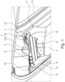
- Fig.1 shows a schematic and perspective representation of an embodiment of a center console 1 according to the invention for a vehicle not shown.
- the center console 1 has a receiving space 2 which is permanently open on both sides and is arranged within a base body 3 of the center console 1, on which a lateral opening 13 is formed on each side, via which the receiving space 2 is permanently open on the side.
- the center console 1 has a holder 4 for holding an emergency hammer 5, which is visible from the outside and freely accessible in the receiving space 2 of the center console 1.
- the holder 4 is arranged in a front end area of the receiving space 2 of the center console 1, which is accessible via the side openings 13.
- Center console 1. The holder 4 is designed such that a handle 6 of the emergency hammer 5 arranged on the holder 4 runs in a transverse direction of the center console 1.
- the emergency hammer 5 also has a hammer head 7, which can be struck against a window of the vehicle in order to break it if necessary. Between the hammer head 7 and the handle 6, the emergency hammer 5 has a tapered transition section 8.
- the tapered transition section 8 is also advantageous in terms of easier gripping when releasing, which leads to the Figures 3a to 3c will be described later.
- the holder 4 has a handle holding unit 9 and a head holding unit 10 arranged in the transverse direction of the center console 1 at a distance from the handle holding unit 9.
- the handle holding unit 9 has a recess 11 which is open upwards with respect to a height direction of the center console 1 and in the direction of the head holding unit 10 for at least partially receiving the handle 6 and into which the handle 6 is partially inserted.
- the head holding unit 10 has a recess 12 which is open upwards with respect to the height direction of the center console 1 and in the direction of the handle holding unit 9 for at least partially receiving the hammer head 7 and into which the hammer head 7 is partially inserted.
- the handle holding unit 9 and the head holding unit 10 are at least partially manufactured monolithically with the base body 3 of the center console 1 which delimits the receiving space 2.
- a rigid retaining projection 15 extending to the rear is formed on the handle holding unit 9 and the head holding unit 10, which partially closes the respective recess 11 or 12 at the front and thereby partially surrounds or covers the handle 6 or the hammer head 7 in the rest position of the emergency hammer 5 shown.
- the emergency hammer 5 cannot be moved vertically upwards out of the recesses 11 and 12 in order to release the emergency hammer 5 from the center console.
- the emergency hammer 5 can only be released from the center console 1 by a rotational movement according to the arrow 14 shown, as will be explained below with reference to the Figs. 3a to 3c
- the holder 4 has at least one in the Figs. 3a to 3c shown pretensioning element 20, with which the emergency hammer 5 is pretensioned in the direction of the rest position.
- Fig.2 shows a schematic and perspective view of the Fig.1 shown emergency hammer 5.
- the hammer head 7 has a cylindrical impact element 16 which is cast into the rest of the hammer head 7, whereby the emergency hammer 5 can also be made of a plastic.
- the impact element 16 has a conical impact tip 17 which can be brought into contact with a disk to be struck.
- the head holding unit 10 in particular for the hammer head 7 with impact tip 17 is preferably shaped in such a way that for a Figures 3a to 3c corresponding free space exists for the rotational movement described.
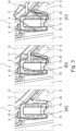
- FIGS 3a-c show schematic sectional views of the Fig.1 shown center console 1 with different positions of the emergency hammer 5.
- the sectional views show longitudinal sections of the center console 1 in the area of the handle holding unit 9.
- FIGs 4a to c is a perspective view of the emergency hammer 5 in the receiving space 2 of the center console 1 with a section through the handle holding unit 9, wherein the representation of the Figures 3a to c with the Figures 4a to c correlate with each other.
- a handle holding projection 18 extending in the transverse direction of the center console 1 is arranged on a base of the recess 11, which engages in a holding recess 19 extending in the longitudinal direction of the emergency hammer 5 on its handle 7.
- the handle 7 is secured in the longitudinal direction of the center console 1 on the handle holding unit 9.
- the holding projection 15 prevents the handle 6 from automatically lifting off the handle holding projection 18.
- a pre-tensioning element 20 with an L-shaped cross section, with which the handle 6 can be pushed into the Fig. 3a and Fig. 4a shown position is pre-tensioned, so that the handle 7 and thus also the emergency hammer 5 as a whole does not move according to the Fig.1 shown arrow relative to the center console 1 and thus cannot automatically detach from the center console 1 while the vehicle is moving or in the event of an extreme event.
- the movement sequence is particularly advantageous if the emergency hammer 5 is removed from the receiving space 2 blindly, i.e. without looking. Once the emergency hammer 5 has been removed from the recess 11, the pre-tensioning element 20 automatically deforms back into the Figure 3a shown state. The arrangement of the emergency hammer 5 in the recess 11 is then carried out by reversing the previously described steps.
- the recess 12 is open at the bottom so that the hammer head 7, in particular its impact element 1 with impact tip 17, can be accommodated.
- the hammer head 7 is locked in the recess 12 and held securely in position by means of the retaining projection 15.
- the pre-tensioning element 20 can also be seen.
- the hammer head 7 with its impact element 16 can rotate freely, i.e. without hindrance, since the head holding unit 10 offers sufficient space, as in Figure 4b and 4c is best recognized.
- the movement sequence is as in the Figures 3a to c described to which reference is made.
- FIG 6 is an enlargement of the sectional view from Figure 3a shown.
- the pre-tensioning element 20 rests on one side of the handle 6 and presses the emergency hammer 5, i.e. the handle 6, onto the opposite contact points of the handle holding unit 9, so that the emergency hammer 5 is held securely in position together with the holding projection 15.
- Figure 7 is an enlargement of the sectional view from Figure 5a shown.
- the pre-tensioning element 20 rests on one side of the hammer head 7 and, together with the holding projection 15, ensures that the emergency hammer 5 is also held securely in position on the head side.
Landscapes
- Health & Medical Sciences (AREA)
- General Health & Medical Sciences (AREA)
- Business, Economics & Management (AREA)
- Emergency Management (AREA)
- Engineering & Computer Science (AREA)
- Mechanical Engineering (AREA)
- Vehicle Step Arrangements And Article Storage (AREA)
Abstract
Description
- Die Erfindung betrifft eine Mittelkonsole für ein Fahrzeug, aufweisend wenigstens eine Halterung zum Halten eines Nothammers, sowie ein Fahrzeug mit einer Mittelkonsole.
- Eine Mittelkonsole eines Fahrzeugs verläuft üblicherweise von einem Kniebereich zwischen zwei vorderen Fußräumen heckseitig bis zwischen zwei Vordersitze. Derartige Mittelkonsolen können sehr unterschiedlich ausgebildet sein und weisen meist wenigstens eine Funktionseinheit auf, wie beispielsweise einen Getränkehalter oder dergleichen.
- Die
CN 210 970 890 U offenbart eine Halterung für einen Nothammer für ein Fahrzeug, wobei die Halterung einen Aufnahmekörper zum Aufnehmen des Nothammers und einen Sensoreinheit aufweist, um das Fehlen des Nothammers in der Halterung feststellen und anzeigen zu können. - Die
CN 2 05 239 375 U zeigt eine Halterung für einen Nothammer, die seitlich an einer Fahrzeug-Mittelkonsole angebracht ist. - Die
DE 202 20 953 U1 offenbart eine Anordnung eines Nothammers und eines Wandhalters insbesondere zum Gebrauch in öffentlichen Verkehrsmitteln oder in öffentlichen Räumen, wobei Kupplungsmittel vorgesehen sind, um den Nothammer an den Wandhalter zu koppeln. Die Kupplungsmittel umfassen Verbindungsmittel, die die Entfernung der Kupplungsmittel oder des Nothammers nur ermöglichen, nachdem die Kupplungsmittel und/oder die Verbindungsmittel zerbrochen wurden. - Die
JP 5 773 778 B2 - Der Erfindung liegt die Aufgabe zugrunde, einen Nothammer innerhalb eines Fahrgastraums eines Fahrzeugs lagestabil sowie frei und einfach zugänglich aufzubewahren.
- Erfindungsgemäß wird die Aufgabe durch eine Mittelkonsole mit den Merkmalen des Anspruchs 1 gelöst.
- Es ist darauf hinzuweisen, dass die in der nachfolgenden Beschreibung einzeln aufgeführten Merkmale sowie Maßnahmen in beliebiger technisch sinnvoller Weise miteinander kombiniert werden können und weitere Ausgestaltungen der Erfindung aufzeigen. Die Beschreibung charakterisiert und spezifiziert die Erfindung insbesondere im Zusammenhang mit den Figuren zusätzlich.
- Gemäß der Erfindung weist die Halterung eine Griffhalteeinheit mit einer nach oben offenen Ausnehmung zum zumindest teilweisen Aufnehmen eines Griffs des Nothammers und eine in Querrichtung der Mittelkonsole beabstandet von der Griffhalteeinheit angeordnete Kopfhalteeinheit mit einer nach oben offenen Ausnehmung zum zumindest teilweisen Aufnehmen eines Hammerkopfes des Nothammers auf, wobei der an der Halterung angeordnete Nothammer mittels wenigstens eines Vorspannelements in Richtung einer Ruhestellung vorgespannt ist, in der wenigstens ein sich heckseitig erstreckender Haltevorsprung der Griffhalteeinheit und/oder der Kopfhalteeinheit, der die Ausnehmung frontseitig oben teilweise verschließt, den Griff bzw. den Hammerkopf zumindest teilweise oben abdeckt. Hierdurch wird der Nothammer in seiner Ruhestellung derart von der Halterung gehalten, dass sich der Nothammer nicht selbsttätig von der Halterung lösen kann, auch nicht im Falle eines Extremereignisses. Der Nothammer kann nur derart von der Halterung gelöst werden, wenn der Nothammer zunächst gegen die Wirkung der Vorspanneinheit in Längsrichtung der Mittelkonsole heckseitig verlagert wird, so dass der Griff bzw. der Hammerkopf des Nothammers nicht mehr oben von dem Haltevorsprung abgedeckt ist. Die Vorspanneinheit kann für ihre Funktion wenigstens ein Federelement aufweisen. Die Griffhalteeinheit und/oder die Kopfhalteeinheit kann wenigstens eine Führungskontur aufweisen, mit der der Nothammer beim Anbringen an der Halterung und/oder beim Entfernen von der Halterung geführt wird, so dass das Anbringen bzw. Entfernen des Nothammers erleichtert und intuitiver gemacht wird. Die Bewegung zum Entfernen bzw. Anbringen des Nothammers kann beispielsweise eine Kombination aus einer linearen Bewegung des Nothammers und einer Rotationsbewegung des Nothammers sein.
- Die Halterung ist vorzugsweise derart ausgebildet, dass der Nothammer während einer Fahrt des Fahrzeugs geräuschfrei an der Halterung angeordnet ist. Zudem ist die Halterung vorzugsweise derart ausgebildet, dass sich der Nothammer selbst im Falle eines Extremereignisses nicht selbststätig durch die auf ihn einwirkenden Trägheitskräfte von der Halterung lösen kann.
- Vorzugsweise ist die Halterung derart ausgebildet, dass ein Griff eines an der Halterung angeordneten Nothammers in einer Querrichtung der Mittelkonsole verläuft. Hierdurch kann der Griff des Nothammers mit der Hand intuitiv und einfach ergriffen werden, um den Nothammer dem Aufnahmeraum entnehmen zu können. Dies ist insbesondere von Vorteil, wenn die Halterung derart ausgebildet ist, dass der Nothammer erst nach Aufbringen einer bestimmten Kraft von der Halterung gelöst werden kann.
- Die erfindungsgemäße Mittelkonsole kann insbesondere in einem Fahrzeug in Form eines Kraftwagens, beispielsweise eines Personenkraftwagens oder Nutzkraftwagens, verbaut sein. Ein solches Fahrzeug stellt daher einen weiteren erfindungsgemäßen Aspekt dar. Ebenso stellt eine erfindungsgemäße Mittelkonsole zusammen mit einem daran angeordneten Nothammer einen Aspekt der Erfindung dar.
- Gemäß einer vorteilhaften Ausgestaltung ist die Halterung von außen frei zugänglich in einem seitlich dauerhaft offenen Aufnahmeraum der Mittelkonsole angeordnet. Hierdurch ist der Nothammer ergonomisch in dem Aufnahmeraum bzw. der Mittelkonsole des Fahrzeugs angeordnet, also in einem Bereich des Fahrgastinnenraums, der für eine auf einem Vordersitz des Fahrzeugs sitzende Person sehr gut zugänglich ist, selbst wenn die Person mit einem Sicherheitsgurt an den Vordersitz angeschnallt ist. Da der Aufnahmeraum der Mittelkonsole dauerhaft offen ist, muss zur Zugänglichmachung des Nothammers nicht erst eine Klappe geöffnet werden, was im Übrigen im Falle eines Extremereignisses durch Verformungen von Fahrzeugkomponenten erschwert oder unmöglich gemacht sein kann, so dass im schlimmsten Fall nicht auf den Nothammer zugegriffen werden könnte. Stattdessen ist der Nothammer von außen bzw. von außerhalb der Mittelkonsole frei zugänglich in dem Aufnahmeraum angeordnet, und zwar über eine seitliche Öffnung des Aufnahmeraums, über die eine auf einem Vordersitz sitzende Person, auf deren Seite der Mittelkonsole die seitliche Öffnung angeordnet ist, in den offenen Aufnahmeraum sehen und den Nothammer erblicken kann. Die Person kann also ihre Hand zielgerichtet und somit schnell zu dem Nothammer bewegen, um den Nothammer ergreifen, dem Aufnahmeraum entnehmen und zum Einschlagen einer Scheibe des Fahrzeugs verwenden zu können. Die Mittelkonsole bzw. deren Aufnahmeraum kann auch auf beiden Seiten jeweils eine solche seitliche Öffnung aufweisen, so dass sowohl eine auf dem Fahrersitz sitzende Person, als auch eine auf dem Beifahrersitz sitzende Person nach dem Nothammer greifen kann. In jedem Fall ist der Nothammer in einer sichtbaren Position innerhalb des Aufnahmeraums der Mittelkonsole, die technische Funktion der Mittelkonsole erweiternd störungsfrei angeordnet.
- Die Halterung zum Halten des Nothammers ist vorzugsweise vollständig innerhalb des Aufnahmeraums der Mittelkonsole angeordnet, so dass auch der an der Halterung angeordnete Nothammer vollständig innerhalb des Aufnahmeraums angeordnet ist.
- Gemäß einer weiteren vorteilhaften Ausgestaltung ist die Halterung zumindest teilweise monolithisch mit einem den Aufnahmeraum begrenzenden Grundkörper der Mittelkonsole hergestellt. Hierdurch kann eine Montage separater Halterungsteile an der übrigen Mittelkonsole weitestgehend reduziert werden, was die Herstellung der Mittelkonsole vereinfacht und die Mittelkonsole mit der Halterung robuster macht. Alternativ ist es aber auch möglich, die Halterung vollständig separat herzustellen und an der übrigen Mittelkonsole anzubringen, beispielsweise mittels mechanischer Befestigungsmittel.
- Gemäß einer weiteren vorteilhaften Ausgestaltung ist die Halterung in einem frontseitigen Endbereich des über seitliche Öffnungen zugänglichen Aufnahmeraums der Mittelkonsole angeordnet. Eine auf einem Vordersitz des Fahrzeugs sitzende Person kann diesen frontseitigen Bereich des Aufnahmeraums direkt einsehen, was das Ergreifen des Nothammers vereinfacht.
- Weitere vorteilhafte Ausgestaltungen der Erfindung sind in den Unteransprüchen und der folgenden Figurenbeschreibung offenbart. Es zeigt:
- Fig. 1
- eine schematische und perspektivische Darstellung eines Ausführungsbeispiels für eine erfindungsgemäße Mittelkonsole;
- Fig. 2
- eine schematische und perspektivische Darstellung des in
Fig. 1 gezeigten Nothammers; - Fig. 3a-c
- schematische Schnittdarstellungen der in
Fig. 1 gezeigten Mittelkonsole mit verschiedenen Stellungen des Nothammers; - Fig. 4a-c
- eine perspektivische Darstellung des Nothammers in dem Aufnahmeraum der Mittelkonsole mit Schnitt durch die Griffhalteeinheit wie zu den
Figuren 3a bis c; - Fig. 5a-c
- eine perspektivische Darstellung des Nothammers in dem Aufnahmeraum der Mittelkonsole mit Schnitt durch die Kopfhalteeinheit korrelierend zu den
Figuren 3a bis c; - Fig. 6
- eine vergrößerte Schnittdarstellung gemäß
Figur 3a ; und - Fig. 7
- eine vergrößerte Schnittdarstellung gemäß
Figur 5a - In den unterschiedlichen Figuren sind gleiche Teile stets mit denselben Bezugszeichen versehen, weswegen diese in der Regel auch nur einmal beschrieben werden.
-
Fig. 1 zeigt eine schematische und perspektivische Darstellung eines Ausführungsbeispiels für eine erfindungsgemäße Mittelkonsole 1 für ein nicht gezeigtes Fahrzeug. - Die Mittelkonsole 1 weist einen beidseitig seitlich dauerhaft offenen Aufnahmeraum 2 auf, der innerhalb eines Grundkörpers 3 der Mittelkonsole 1 angeordnet ist, an dem an jeder Seite eine seitliche Öffnung 13 ausgebildet ist, über die der Aufnahmeraum 2 seitlich dauerhaft offen ist.
- Zudem weist die Mittelkonsole 1 eine Halterung 4 zum Halten eines Nothammers 5 auf, der von außen sichtbar und frei zugänglich in dem Aufnahmeraum 2 der Mittelkonsole 1 angeordnet ist. Insbesondere ist die Halterung 4 in einem frontseitigen Endbereich des über die seitlichen Öffnungen 13 zugänglichen Aufnahmeraums 2 der Mittelkonsole 1 angeordnet ist. Dabei ist die Halterung 4 derart ausgebildet, dass ein Griff 6 des an der Halterung 4 angeordneten Nothammers 5 in einer Querrichtung der Mittelkonsole 1 verläuft.
- Der Nothammer 5 weist zudem einen Hammerkopf 7 auf, der gegen eine Scheibe des Fahrzeugs geschlagen werden kann, um diese bei Bedarf einzuschlagen. Zwischen dem Hammerkopf 7 und dem Griff 6 weist der Nothammer 5 einen verjüngten Übergangsabschnitt 8 auf. Der verjüngte Übergangsabschnitt 8 ist auch vorteilhaft hinsichtlich eines erleichterten Greifens bei dem Lösen, was zu den
Figuren 3a bis 3c noch beschrieben wird. - Die Halterung 4 weist eine Griffhalteeinheit 9 und eine in der Querrichtung der Mittelkonsole 1 beabstandet von der Griffhalteeinheit 9 angeordnete Kopfhalteeinheit 10 auf. Die Griffhalteeinheit 9 weist eine bezüglich einer Höhenrichtung der Mittelkonsole 1 nach oben und in Richtung der Kopfhalteeinheit 10 offene Ausnehmung 11 zum zumindest teilweisen Aufnehmen des Griffs 6 auf, in die der Griff 6 teilweise eingefügt ist. Die Kopfhalteeinheit 10 weist eine bezüglich der Höhenrichtung der Mittelkonsole 1 nach oben und in Richtung der Griffhalteeinheit 9 offene Ausnehmung 12 zum zumindest teilweisen Aufnehmen des Hammerkopfes 7 auf, in die der Hammerkopf 7 teilweise eingefügt ist. Die Griffhalteeinheit 9 und die Kopfhalteeinheit 10 sind zumindest teilweise monolithisch mit dem, den Aufnahmeraum 2 begrenzenden Grundkörper 3 der Mittelkonsole 1 hergestellt.
- An der Griffhalteeinheit 9 und der Kopfhalteeinheit 10 ist jeweils ein starr ausgebildeter, sich heckseitig erstreckender Haltevorsprung 15 ausgebildet, der die jeweilige Ausnehmung 11 bzw. 12 frontseitig teilweise verschließt und dadurch den Griff 6 bzw. den Hammerkopf 7 in der gezeigten Ruhestellung des Nothammers 5 oben teilweise umgreift bzw. abdeckt. Hierdurch kann der Nothammer 5 nicht vertikal nach oben aus den Ausnehmungen 11 und 12 herausbewegt werden, um den Nothammer 5 von der Mittelkonsole zu lösen. Stattdessen kann der Nothammer 5 nur durch eine Drehbewegung entsprechend dem gezeigten Pfeil 14 von der Mittelkonsole 1 gelöst werden, wie es nachfolgend mit Bezug auf die
Fign. 3a bis 3c beschrieben ist. Die Halterung 4 weist wenigstens ein in denFign. 3a bis 3c gezeigtes Vorspannelement 20 auf, mit dem der Nothammer 5 in Richtung der Ruhestellung vorgespannt ist. -
Fig. 2 zeigt eine schematische und perspektivische Darstellung des inFig. 1 gezeigten Nothammers 5. Es sind insbesondere der Griff 6 und der Hammerkopf 7 vollständig gezeigt. Der Hammerkopf 7 weist ein zylinderförmiges Einschlagelement 16 auf, das in den übrigen Hammerkopf 7 eingegossen ist, wobei der Nothammer 5 im Übrigen aus einem Kunststoff hergestellt sein kann. Das Einschlagelement 16 weist eine in Kontakt mit einer einzuschlagenden Scheibe bringbare kegelförmige Schlagspitze 17 auf. Die Kopfhalteeinheit 10 im speziellen für den Hammerkopf 7 mit Schlagspitze 17 ist bevorzugt so ausgeformt, das für eine wie zu denFiguren 3a bis 3c beschriebene Rotationsbewegung entsprechender Freiraum existiert. - Die
Figuren 3a-c zeigen schematische Schnittdarstellungen der inFig. 1 gezeigten Mittelkonsole 1 mit verschiedenen Stellungen des Nothammers 5. Die Schnittdarstellungen zeigen Längsschnitte der Mittelkonsole 1 im Bereich der Griffhalteeinheit 9. In denFiguren 4a bis c ist eine perspektivische Darstellung des Nothammers 5 in dem Aufnahmeraum 2 der Mittelkonsole 1 mit Schnitt durch die Griffhalteeinheit 9 gezeigt, wobei die Darstellung derFiguren 3a bis c mit denFiguren 4a bis c einander korrelieren. - Wie in
Figur 3a und4a zu erkennen ist, ist an einem Boden der Ausnehmung 11 ein sich in Querrichtung der Mittelkonsole 1 erstreckender Griffhaltevorsprung 18 angeordnet, der in eine sich in Längsrichtung des Nothammers 5 an dessen Griff 7 erstreckende Halteausnehmung 19 eingreift. Hierdurch wird der Griff 7 in Längsrichtung der Mittelkonsole 1 an der Griffhalteeinheit 9 gesichert. Dabei verhindert der Haltevorsprung 15, dass der Griff 6 selbsttätig von dem Griffhaltevorsprung 18 abhebt. - In der Ausnehmung 11 ist zudem ein im Querschnitt L-förmig ausgebildetes Vorspannelement 20 angeordnet, mit dem der Griff 6 in die in
Fig. 3a undFig. 4a gezeigte Stellung vorgespannt ist, so dass sich der Griff 7 und dadurch auch nicht der Nothammer 5 insgesamt entsprechend dem inFig. 1 gezeigten Pfeil relativ zu der Mittelkonsole 1 drehen und sich somit während der Fahrt des Fahrzeugs oder eines Extremereignisses nicht selbsttätig von der Mittelkonsole 1 lösen kann. - In
Fig. 3b und4b ist der Griff 6 bereits entsprechend dem Pfeil 21 um den Griffhaltevorsprung 18 verschwenkt worden, wodurch der Haltevorsprung 15 den Griff 6 nicht mehr oben abdeckt, der Griff 6 also von dem Haltevorsprung 15 gelöst ist. Dabei ist das Vorspannelement 20 gegen seine Vorspannwirkungsrichtung elastisch verformt worden. Ab dieser Stellung des Griffs 6 bzw. Nothammers 5 relativ zu der Mittelkonsole 1 kann der Griff 6 bzw. der Nothammer 5 nach schräg oben und heckseitig aus der Ausnehmung 11 herausbewegt werden, was einem Nutzer eine intuitive Handhabung des Nothammers 5 ermöglicht. Diese Position ist inFigur 3c und4c dargestellt. - Der Bewegungsablauf ist insbesondere von Vorteil, wenn die Entnahme des Nothammers 5 aus dem Aufnahmeraum 2 blind, also ohne Hinsehen durchgeführt wird. Ist der Nothammer 5 der Ausnehmung 11 entnommen worden, verformt sich das Vorspannelement 20 selbsttätig wieder in den in
Figur 3a gezeigten Zustand. Das Anordnen des Nothammers 5 an der Ausnehmung 11 erfolgt dann durch eine Umkehrung der vorbeschriebenen Schritte. - In den
Figuren 5a bis c eine perspektivische Darstellung des Nothammers 5 in dem Aufnahmeraum 2 der Mittelkonsole 1 mit Schnitt durch die Kopfhalteeinheit 10 sowie den Hammerkopf 7 mit Einschlagelement 16 dargestellt, wobei der Bewegungsablauf mit denFiguren 3 bis c korreliert. - Wie in
Figur 5a zu erkennen ist, ist die Ausnehmung 12 bodenseitig geöffnet, so dass der Hammerkopf 7, insbesondere dessen Einschlagelement 1 mit Schlagspitze 17 aufnehmbar ist. Der Hammerkopf 7 ist in der Ausnehmung 12 arretiert und mittels des Haltevorsprungs 15 lagesicher gehalten. Auch das Vorspannelement 20 ist erkennbar. Der Hammerkopf 7 mit seinem Einschlagelement 16 kann frei, also ohne Behinderung rotieren, da die Kopfhalteeinheit 10 genügend Freiraum bietet, wie inFigur 4b und 4c am besten erkennbar ist. Der Bewegungsablauf ist wie zu denFiguren 3a bis c beschrieben, worauf Bezug genommen wird. - In
Figur 6 ist eine Vergrößerung der Schnittdarstellung ausFigur 3a gezeigt. Das Vorspannelement 20 liegt einseitig an dem Griff 6 an, und drückt den Nothammer 5, also den Griff 6 an dazu gegenüberliegenden Anlagepunkte der Griffhalteeinheit 9 an, so dass der Nothammer 5 zusammen mit dem Haltevorsprung 15 lagesicher gehalten ist. InFigur 7 ist eine Vergrößerung der Schnittdarstellung ausFigur 5a gezeigt. Das Vorspannelement 20 liegt einseitig an dem Hammerkopf 7 an, und sorgt so zusammen mit dem Haltevorsprung 15 dafür, dass der Nothammer 5 auch kopfseitig lagesicher gehalten ist. -
- 1
- Mittelkonsole
- 2
- Aufnahmeraum
- 3
- Grundkörper
- 4
- Halterung
- 5
- Nothammer
- 6
- Griff
- 7
- Hammerkopf
- 8
- Übergangsabschnitt
- 9
- Griffhalteeinheit
- 10
- Kopfhalteeinheit
- 11
- Ausnehmung an 9
- 12
- Ausnehmung an 10
- 13
- seitliche Öffnung an 3
- 14
- Pfeil
- 15
- Haltevorsprung
- 16
- Einschlagelement
- 17
- Schlagspitze
- 18
- Griffhaltevorsprung
- 19
- Halteausnehmung
- 20
- Vorspannelement
- 21
- Pfeil
Claims (5)
- Mittelkonsole (1) für ein Fahrzeug, aufweisend wenigstens eine Halterung (4) zum Halten eines Nothammers (5),
dadurch gekennzeichnet, dass
die Halterung (4) eine Griffhalteeinheit (9) mit einer nach oben offenen Ausnehmung (11) zum zumindest teilweisen Aufnehmen eines Griffs (6) des Nothammers (5) und eine in Querrichtung der Mittelkonsole (1) beabstandet von der Griffhalteeinheit (9) angeordnete Kopfhalteeinheit (10) mit einer nach oben offenen Ausnehmung (12) zum zumindest teilweisen Aufnehmen eines Hammerkopfes (7) des Nothammers (5) aufweist, wobei der an der Halterung (4) angeordnete Nothammer (5) mittels wenigstens eines Vorspannelements (20) in Richtung einer Ruhestellung vorgespannt ist, in der wenigstens ein sich heckseitig erstreckender Haltevorsprung (15) der Griffhalteeinheit (9) und/oder der Kopfhalteeinheit (10), der die Ausnehmung (11) bzw. die Ausnehmung (12) frontseitig oben teilweise verschließt, den Griff (6) bzw. den Hammerkopf (7) zumindest teilweise oben abdeckt.. - Mittelkonsole (1) nach Anspruch 1,
dadurch gekennzeichnet, dass
die Halterung (4) von außen frei zugänglich in einem seitlich dauerhaft offenen Aufnahmeraum (2) der Mittelkonsole (1) angeordnet ist. - Mittelkonsole (1) nach Anspruch 1 oder 2,
dadurch gekennzeichnet, dass
die Halterung (4) zumindest teilweise monolithisch mit einem den Aufnahmeraum (2) begrenzenden Grundkörper (3) der Mittelkonsole (1) hergestellt ist. - Mittelkonsole (1) nach einem der vorhergehenden Ansprüche,
dadurch gekennzeichnet, dass
die Halterung (4) in einem frontseitigen Endbereich des über seitliche Öffnungen (13) zugänglichen Aufnahmeraums (2) der Mittelkonsole (1) angeordnet ist. - Fahrzeug mit einer Mittelkonsole (1) nach einem der vorhergehenden Ansprüche.
Applications Claiming Priority (1)
| Application Number | Priority Date | Filing Date | Title |
|---|---|---|---|
| DE102022130418.3A DE102022130418A1 (de) | 2022-11-17 | 2022-11-17 | Mittelkonsole für ein Fahrzeug |
Publications (2)
| Publication Number | Publication Date |
|---|---|
| EP4371619A1 true EP4371619A1 (de) | 2024-05-22 |
| EP4371619B1 EP4371619B1 (de) | 2025-06-18 |
Family
ID=90825315
Family Applications (1)
| Application Number | Title | Priority Date | Filing Date |
|---|---|---|---|
| EP23189979.0A Active EP4371619B1 (de) | 2022-11-17 | 2023-08-07 | Mittelkonsole für ein fahrzeug |
Country Status (3)
| Country | Link |
|---|---|
| EP (1) | EP4371619B1 (de) |
| DE (1) | DE102022130418A1 (de) |
| ES (1) | ES3041960T3 (de) |
Citations (8)
| Publication number | Priority date | Publication date | Assignee | Title |
|---|---|---|---|---|
| DE20220953U1 (de) | 2002-10-22 | 2004-09-23 | Life Safety Products B.V. | System umfassend einen Nothammer und einen Wandhalter |
| DE202010000109U1 (de) * | 2010-02-01 | 2010-04-08 | Böttner, Rene | Nothammer |
| JP5773778B2 (ja) | 2011-06-27 | 2015-09-02 | 鉦治 二村 | 緊急脱出用工具 |
| US20160038773A1 (en) * | 2013-10-18 | 2016-02-11 | Shanghai Easy-Use Tools Enterprise Co., Ltd | Multi-functional car power receptacle having lifesaving tool |
| CN205239375U (zh) | 2015-11-24 | 2016-05-18 | 江苏韩一模塑有限公司 | 一种车载安全锤收纳装置 |
| CN208423842U (zh) * | 2018-06-19 | 2019-01-22 | 亚帝森能源科技(深圳)有限公司 | 一种具有指示及救生功能的车载充电器 |
| US10189152B2 (en) * | 2012-02-27 | 2019-01-29 | Life Safety Products B.V. | Safety hammer for breaking glass, method for assembly of a safety hammer, safety tool holder, system for holding a safety tool and kit of parts |
| CN210970890U (zh) | 2019-10-12 | 2020-07-10 | 中山安信通机器人制造有限公司 | 车用安全锤放置装置及汽车 |
-
2022
- 2022-11-17 DE DE102022130418.3A patent/DE102022130418A1/de active Pending
-
2023
- 2023-08-07 ES ES23189979T patent/ES3041960T3/es active Active
- 2023-08-07 EP EP23189979.0A patent/EP4371619B1/de active Active
Patent Citations (8)
| Publication number | Priority date | Publication date | Assignee | Title |
|---|---|---|---|---|
| DE20220953U1 (de) | 2002-10-22 | 2004-09-23 | Life Safety Products B.V. | System umfassend einen Nothammer und einen Wandhalter |
| DE202010000109U1 (de) * | 2010-02-01 | 2010-04-08 | Böttner, Rene | Nothammer |
| JP5773778B2 (ja) | 2011-06-27 | 2015-09-02 | 鉦治 二村 | 緊急脱出用工具 |
| US10189152B2 (en) * | 2012-02-27 | 2019-01-29 | Life Safety Products B.V. | Safety hammer for breaking glass, method for assembly of a safety hammer, safety tool holder, system for holding a safety tool and kit of parts |
| US20160038773A1 (en) * | 2013-10-18 | 2016-02-11 | Shanghai Easy-Use Tools Enterprise Co., Ltd | Multi-functional car power receptacle having lifesaving tool |
| CN205239375U (zh) | 2015-11-24 | 2016-05-18 | 江苏韩一模塑有限公司 | 一种车载安全锤收纳装置 |
| CN208423842U (zh) * | 2018-06-19 | 2019-01-22 | 亚帝森能源科技(深圳)有限公司 | 一种具有指示及救生功能的车载充电器 |
| CN210970890U (zh) | 2019-10-12 | 2020-07-10 | 中山安信通机器人制造有限公司 | 车用安全锤放置装置及汽车 |
Also Published As
| Publication number | Publication date |
|---|---|
| EP4371619B1 (de) | 2025-06-18 |
| DE102022130418A1 (de) | 2024-05-23 |
| ES3041960T3 (en) | 2025-11-17 |
Similar Documents
| Publication | Publication Date | Title |
|---|---|---|
| EP1964715B1 (de) | Adaptervorrichtung für einen Haltegriff | |
| EP0649778A1 (de) | Sicherheitsnetzanordnung | |
| EP1072485A2 (de) | Sicherheitsgurtsystem | |
| WO2005065988A1 (de) | Verriegelungsvorrichtung für einen fahrzeugsitz | |
| EP2029389B1 (de) | Betätigungsvorrichtung zur kopfstützenverstellung und kopfstützendemontage unter berücksichtigung des fmvss 202a-standards | |
| DE202010000109U1 (de) | Nothammer | |
| EP4371619B1 (de) | Mittelkonsole für ein fahrzeug | |
| DE102008032324A1 (de) | Blockiervorrichtung für einen Betätigungszug, insbesondere Bowdenzug, einer Schließvorrichtung eines beweglichen Karosserieteils eines Fahrzeugs | |
| DE10222836B4 (de) | Kfz-Sicherheitseinrichtung, wie Laderaumabdeckung, Trennnetz o. dgl. | |
| DE10009291A1 (de) | Armlehne mit Staufach und verriegelbarem Deckel | |
| DE10052829B4 (de) | Vorrichtung zur Arretierung eines beweglichen Körpers, insbesondere in einem Kfz und Armlehne | |
| EP2853664B1 (de) | Türgriff | |
| DE10355780A1 (de) | Vorrichtung zur Verriegelung eines ersten Fahrzeugteiles an einem zweiten Fahrzeugteil | |
| DE102009043038A1 (de) | Anzeigeeinrichtung für ein Kraftfahrzeug und Kraftfahrzeug | |
| DE102023119448A1 (de) | Türgriffanordnung mit als trägheitssperre ausgeführter crashsperre | |
| DE102008015231B4 (de) | Abdeck- und/oder Trennvorrichtung für einen Gepäckraum eines Kraftfahrzeuges | |
| DE10360113B4 (de) | Einrichtung zum Öffnen und Schließen von Abdeckungen | |
| DE102010032677B4 (de) | Verschwenkbare Kopfstütze | |
| EP2882614A1 (de) | Einrichtung zur anordnung einer warnwesteneinrichtung an einer seitentür eines kraftwagens | |
| DE10218631C1 (de) | Kfz-Sicherheitseinrichtung, wie Laderaumabdeckung, Trennnetz od. dgl. | |
| DE102020005117A1 (de) | Innenspiegel für einen Innenraum eines Kraftwagens | |
| DE10103245C1 (de) | Überrollschutzsystem für Kraftfahrzeuge | |
| DE102008015618B4 (de) | Laderaumabdeckung | |
| DE102006000909B4 (de) | Überrollschutzsystem für ein Cabriolet-Fahrzeug mit gekrümmtem Überrollkörper | |
| DE10240181B4 (de) | Stossfänger für ein Fahrzeug sowie Fahrzeug mit einem Stossfänger |
Legal Events
| Date | Code | Title | Description |
|---|---|---|---|
| PUAI | Public reference made under article 153(3) epc to a published international application that has entered the european phase |
Free format text: ORIGINAL CODE: 0009012 |
|
| STAA | Information on the status of an ep patent application or granted ep patent |
Free format text: STATUS: THE APPLICATION HAS BEEN PUBLISHED |
|
| AK | Designated contracting states |
Kind code of ref document: A1 Designated state(s): AL AT BE BG CH CY CZ DE DK EE ES FI FR GB GR HR HU IE IS IT LI LT LU LV MC ME MK MT NL NO PL PT RO RS SE SI SK SM TR |
|
| STAA | Information on the status of an ep patent application or granted ep patent |
Free format text: STATUS: REQUEST FOR EXAMINATION WAS MADE |
|
| 17P | Request for examination filed |
Effective date: 20241122 |
|
| RBV | Designated contracting states (corrected) |
Designated state(s): AL AT BE BG CH CY CZ DE DK EE ES FI FR GB GR HR HU IE IS IT LI LT LU LV MC ME MK MT NL NO PL PT RO RS SE SI SK SM TR |
|
| GRAP | Despatch of communication of intention to grant a patent |
Free format text: ORIGINAL CODE: EPIDOSNIGR1 |
|
| STAA | Information on the status of an ep patent application or granted ep patent |
Free format text: STATUS: GRANT OF PATENT IS INTENDED |
|
| RIC1 | Information provided on ipc code assigned before grant |
Ipc: B60R 11/00 20060101ALN20250324BHEP Ipc: B25D 1/00 20060101ALI20250324BHEP Ipc: B60R 11/06 20060101ALI20250324BHEP Ipc: A62B 3/00 20060101AFI20250324BHEP |
|
| INTG | Intention to grant announced |
Effective date: 20250402 |
|
| GRAS | Grant fee paid |
Free format text: ORIGINAL CODE: EPIDOSNIGR3 |
|
| GRAA | (expected) grant |
Free format text: ORIGINAL CODE: 0009210 |
|
| STAA | Information on the status of an ep patent application or granted ep patent |
Free format text: STATUS: THE PATENT HAS BEEN GRANTED |
|
| P01 | Opt-out of the competence of the unified patent court (upc) registered |
Free format text: CASE NUMBER: APP_18416/2025 Effective date: 20250416 |
|
| AK | Designated contracting states |
Kind code of ref document: B1 Designated state(s): AL AT BE BG CH CY CZ DE DK EE ES FI FR GB GR HR HU IE IS IT LI LT LU LV MC ME MK MT NL NO PL PT RO RS SE SI SK SM TR |
|
| REG | Reference to a national code |
Ref country code: GB Ref legal event code: FG4D Free format text: NOT ENGLISH |
|
| REG | Reference to a national code |
Ref country code: CH Ref legal event code: EP |
|
| REG | Reference to a national code |
Ref country code: DE Ref legal event code: R096 Ref document number: 502023001174 Country of ref document: DE |
|
| REG | Reference to a national code |
Ref country code: CH Ref legal event code: EP |
|
| REG | Reference to a national code |
Ref country code: IE Ref legal event code: FG4D Free format text: LANGUAGE OF EP DOCUMENT: GERMAN |
|
| PG25 | Lapsed in a contracting state [announced via postgrant information from national office to epo] |
Ref country code: FI Free format text: LAPSE BECAUSE OF FAILURE TO SUBMIT A TRANSLATION OF THE DESCRIPTION OR TO PAY THE FEE WITHIN THE PRESCRIBED TIME-LIMIT Effective date: 20250618 |
|
| REG | Reference to a national code |
Ref country code: LT Ref legal event code: MG9D |
|
| PG25 | Lapsed in a contracting state [announced via postgrant information from national office to epo] |
Ref country code: GR Free format text: LAPSE BECAUSE OF FAILURE TO SUBMIT A TRANSLATION OF THE DESCRIPTION OR TO PAY THE FEE WITHIN THE PRESCRIBED TIME-LIMIT Effective date: 20250919 Ref country code: NO Free format text: LAPSE BECAUSE OF FAILURE TO SUBMIT A TRANSLATION OF THE DESCRIPTION OR TO PAY THE FEE WITHIN THE PRESCRIBED TIME-LIMIT Effective date: 20250918 |
|
| PG25 | Lapsed in a contracting state [announced via postgrant information from national office to epo] |
Ref country code: BG Free format text: LAPSE BECAUSE OF FAILURE TO SUBMIT A TRANSLATION OF THE DESCRIPTION OR TO PAY THE FEE WITHIN THE PRESCRIBED TIME-LIMIT Effective date: 20250618 |
|
| PG25 | Lapsed in a contracting state [announced via postgrant information from national office to epo] |
Ref country code: HR Free format text: LAPSE BECAUSE OF FAILURE TO SUBMIT A TRANSLATION OF THE DESCRIPTION OR TO PAY THE FEE WITHIN THE PRESCRIBED TIME-LIMIT Effective date: 20250618 |
|
| PGFP | Annual fee paid to national office [announced via postgrant information from national office to epo] |
Ref country code: AT Payment date: 20251020 Year of fee payment: 3 |
|
| PG25 | Lapsed in a contracting state [announced via postgrant information from national office to epo] |
Ref country code: RS Free format text: LAPSE BECAUSE OF FAILURE TO SUBMIT A TRANSLATION OF THE DESCRIPTION OR TO PAY THE FEE WITHIN THE PRESCRIBED TIME-LIMIT Effective date: 20250918 |
|
| REG | Reference to a national code |
Ref country code: NL Ref legal event code: MP Effective date: 20250618 |
|
| PG25 | Lapsed in a contracting state [announced via postgrant information from national office to epo] |
Ref country code: LV Free format text: LAPSE BECAUSE OF FAILURE TO SUBMIT A TRANSLATION OF THE DESCRIPTION OR TO PAY THE FEE WITHIN THE PRESCRIBED TIME-LIMIT Effective date: 20250618 |
|
| PG25 | Lapsed in a contracting state [announced via postgrant information from national office to epo] |
Ref country code: NL Free format text: LAPSE BECAUSE OF FAILURE TO SUBMIT A TRANSLATION OF THE DESCRIPTION OR TO PAY THE FEE WITHIN THE PRESCRIBED TIME-LIMIT Effective date: 20250618 |
|
| REG | Reference to a national code |
Ref country code: ES Ref legal event code: FG2A Ref document number: 3041960 Country of ref document: ES Kind code of ref document: T3 Effective date: 20251117 |
|
| PG25 | Lapsed in a contracting state [announced via postgrant information from national office to epo] |
Ref country code: PT Free format text: LAPSE BECAUSE OF FAILURE TO SUBMIT A TRANSLATION OF THE DESCRIPTION OR TO PAY THE FEE WITHIN THE PRESCRIBED TIME-LIMIT Effective date: 20251020 |
|
| PG25 | Lapsed in a contracting state [announced via postgrant information from national office to epo] |
Ref country code: IS Free format text: LAPSE BECAUSE OF FAILURE TO SUBMIT A TRANSLATION OF THE DESCRIPTION OR TO PAY THE FEE WITHIN THE PRESCRIBED TIME-LIMIT Effective date: 20251018 |
|
| PGFP | Annual fee paid to national office [announced via postgrant information from national office to epo] |
Ref country code: DE Payment date: 20251118 Year of fee payment: 3 |
|
| PG25 | Lapsed in a contracting state [announced via postgrant information from national office to epo] |
Ref country code: SM Free format text: LAPSE BECAUSE OF FAILURE TO SUBMIT A TRANSLATION OF THE DESCRIPTION OR TO PAY THE FEE WITHIN THE PRESCRIBED TIME-LIMIT Effective date: 20250618 |
|
| PGFP | Annual fee paid to national office [announced via postgrant information from national office to epo] |
Ref country code: FR Payment date: 20251111 Year of fee payment: 3 |
|
| PG25 | Lapsed in a contracting state [announced via postgrant information from national office to epo] |
Ref country code: CZ Free format text: LAPSE BECAUSE OF FAILURE TO SUBMIT A TRANSLATION OF THE DESCRIPTION OR TO PAY THE FEE WITHIN THE PRESCRIBED TIME-LIMIT Effective date: 20250618 |
|
| PG25 | Lapsed in a contracting state [announced via postgrant information from national office to epo] |
Ref country code: PL Free format text: LAPSE BECAUSE OF FAILURE TO SUBMIT A TRANSLATION OF THE DESCRIPTION OR TO PAY THE FEE WITHIN THE PRESCRIBED TIME-LIMIT Effective date: 20250618 |
|
| PG25 | Lapsed in a contracting state [announced via postgrant information from national office to epo] |
Ref country code: EE Free format text: LAPSE BECAUSE OF FAILURE TO SUBMIT A TRANSLATION OF THE DESCRIPTION OR TO PAY THE FEE WITHIN THE PRESCRIBED TIME-LIMIT Effective date: 20250618 |
|
| PG25 | Lapsed in a contracting state [announced via postgrant information from national office to epo] |
Ref country code: SK Free format text: LAPSE BECAUSE OF FAILURE TO SUBMIT A TRANSLATION OF THE DESCRIPTION OR TO PAY THE FEE WITHIN THE PRESCRIBED TIME-LIMIT Effective date: 20250618 |
|
| PGFP | Annual fee paid to national office [announced via postgrant information from national office to epo] |
Ref country code: ES Payment date: 20251208 Year of fee payment: 3 |
|
| PG25 | Lapsed in a contracting state [announced via postgrant information from national office to epo] |
Ref country code: RO Free format text: LAPSE BECAUSE OF FAILURE TO SUBMIT A TRANSLATION OF THE DESCRIPTION OR TO PAY THE FEE WITHIN THE PRESCRIBED TIME-LIMIT Effective date: 20250618 |
|
| REG | Reference to a national code |
Ref country code: DE Ref legal event code: R097 Ref document number: 502023001174 Country of ref document: DE |
|
| PG25 | Lapsed in a contracting state [announced via postgrant information from national office to epo] |
Ref country code: MC Free format text: LAPSE BECAUSE OF FAILURE TO SUBMIT A TRANSLATION OF THE DESCRIPTION OR TO PAY THE FEE WITHIN THE PRESCRIBED TIME-LIMIT Effective date: 20250618 |
|
| PG25 | Lapsed in a contracting state [announced via postgrant information from national office to epo] |
Ref country code: DK Free format text: LAPSE BECAUSE OF FAILURE TO SUBMIT A TRANSLATION OF THE DESCRIPTION OR TO PAY THE FEE WITHIN THE PRESCRIBED TIME-LIMIT Effective date: 20250618 |
|
| PG25 | Lapsed in a contracting state [announced via postgrant information from national office to epo] |
Ref country code: IT Free format text: LAPSE BECAUSE OF FAILURE TO SUBMIT A TRANSLATION OF THE DESCRIPTION OR TO PAY THE FEE WITHIN THE PRESCRIBED TIME-LIMIT Effective date: 20250618 Ref country code: LU Free format text: LAPSE BECAUSE OF NON-PAYMENT OF DUE FEES Effective date: 20250807 |
|
| PLBE | No opposition filed within time limit |
Free format text: ORIGINAL CODE: 0009261 |
|
| STAA | Information on the status of an ep patent application or granted ep patent |
Free format text: STATUS: NO OPPOSITION FILED WITHIN TIME LIMIT |
|
| REG | Reference to a national code |
Ref country code: CH Ref legal event code: L10 Free format text: ST27 STATUS EVENT CODE: U-0-0-L10-L00 (AS PROVIDED BY THE NATIONAL OFFICE) Effective date: 20260430 Ref country code: BE Ref legal event code: MM Effective date: 20250831 |
|
| 26N | No opposition filed |
Effective date: 20260319 |
|
| PG25 | Lapsed in a contracting state [announced via postgrant information from national office to epo] |
Ref country code: LT Free format text: LAPSE BECAUSE OF FAILURE TO SUBMIT A TRANSLATION OF THE DESCRIPTION OR TO PAY THE FEE WITHIN THE PRESCRIBED TIME-LIMIT Effective date: 20250618 |
|
| PG25 | Lapsed in a contracting state [announced via postgrant information from national office to epo] |
Ref country code: IE Free format text: LAPSE BECAUSE OF NON-PAYMENT OF DUE FEES Effective date: 20250807 Ref country code: BE Free format text: LAPSE BECAUSE OF NON-PAYMENT OF DUE FEES Effective date: 20250831 |
|
| PG25 | Lapsed in a contracting state [announced via postgrant information from national office to epo] |
Ref country code: SE Free format text: LAPSE BECAUSE OF FAILURE TO SUBMIT A TRANSLATION OF THE DESCRIPTION OR TO PAY THE FEE WITHIN THE PRESCRIBED TIME-LIMIT Effective date: 20250618 |