EP4367433B1 - Beleuchtungsvorrichtung für verbesserte sichtbarkeit - Google Patents
Beleuchtungsvorrichtung für verbesserte sichtbarkeit Download PDFInfo
- Publication number
- EP4367433B1 EP4367433B1 EP22747633.0A EP22747633A EP4367433B1 EP 4367433 B1 EP4367433 B1 EP 4367433B1 EP 22747633 A EP22747633 A EP 22747633A EP 4367433 B1 EP4367433 B1 EP 4367433B1
- Authority
- EP
- European Patent Office
- Prior art keywords
- lighting
- light
- lighting arrangement
- illumination pattern
- optical element
- Prior art date
- Legal status (The legal status is an assumption and is not a legal conclusion. Google has not performed a legal analysis and makes no representation as to the accuracy of the status listed.)
- Active
Links
Images


Classifications
-
- F—MECHANICAL ENGINEERING; LIGHTING; HEATING; WEAPONS; BLASTING
- F21—LIGHTING
- F21S—NON-PORTABLE LIGHTING DEVICES; SYSTEMS THEREOF; VEHICLE LIGHTING DEVICES SPECIALLY ADAPTED FOR VEHICLE EXTERIORS
- F21S8/00—Lighting devices intended for fixed installation
- F21S8/08—Lighting devices intended for fixed installation with a standard
- F21S8/085—Lighting devices intended for fixed installation with a standard of high-built type, e.g. street light
-
- F—MECHANICAL ENGINEERING; LIGHTING; HEATING; WEAPONS; BLASTING
- F21—LIGHTING
- F21V—FUNCTIONAL FEATURES OR DETAILS OF LIGHTING DEVICES OR SYSTEMS THEREOF; STRUCTURAL COMBINATIONS OF LIGHTING DEVICES WITH OTHER ARTICLES, NOT OTHERWISE PROVIDED FOR
- F21V11/00—Screens not covered by groups F21V1/00, F21V3/00, F21V7/00 or F21V9/00
- F21V11/08—Screens not covered by groups F21V1/00, F21V3/00, F21V7/00 or F21V9/00 using diaphragms containing one or more apertures
- F21V11/14—Screens not covered by groups F21V1/00, F21V3/00, F21V7/00 or F21V9/00 using diaphragms containing one or more apertures with many small apertures
-
- F—MECHANICAL ENGINEERING; LIGHTING; HEATING; WEAPONS; BLASTING
- F21—LIGHTING
- F21V—FUNCTIONAL FEATURES OR DETAILS OF LIGHTING DEVICES OR SYSTEMS THEREOF; STRUCTURAL COMBINATIONS OF LIGHTING DEVICES WITH OTHER ARTICLES, NOT OTHERWISE PROVIDED FOR
- F21V3/00—Globes; Bowls; Cover glasses
-
- F—MECHANICAL ENGINEERING; LIGHTING; HEATING; WEAPONS; BLASTING
- F21—LIGHTING
- F21V—FUNCTIONAL FEATURES OR DETAILS OF LIGHTING DEVICES OR SYSTEMS THEREOF; STRUCTURAL COMBINATIONS OF LIGHTING DEVICES WITH OTHER ARTICLES, NOT OTHERWISE PROVIDED FOR
- F21V5/00—Refractors for light sources
-
- F—MECHANICAL ENGINEERING; LIGHTING; HEATING; WEAPONS; BLASTING
- F21—LIGHTING
- F21V—FUNCTIONAL FEATURES OR DETAILS OF LIGHTING DEVICES OR SYSTEMS THEREOF; STRUCTURAL COMBINATIONS OF LIGHTING DEVICES WITH OTHER ARTICLES, NOT OTHERWISE PROVIDED FOR
- F21V5/00—Refractors for light sources
- F21V5/04—Refractors for light sources of lens shape
- F21V5/048—Refractors for light sources of lens shape the lens being a simple lens adapted to cooperate with a point-like source for emitting mainly in one direction and having an axis coincident with the main light transmission direction, e.g. convergent or divergent lenses, plano-concave or plano-convex lenses
-
- F—MECHANICAL ENGINEERING; LIGHTING; HEATING; WEAPONS; BLASTING
- F21—LIGHTING
- F21W—INDEXING SCHEME ASSOCIATED WITH SUBCLASSES F21K, F21L, F21S and F21V, RELATING TO USES OR APPLICATIONS OF LIGHTING DEVICES OR SYSTEMS
- F21W2131/00—Use or application of lighting devices or systems not provided for in codes F21W2102/00-F21W2121/00
- F21W2131/10—Outdoor lighting
- F21W2131/103—Outdoor lighting of streets or roads
-
- F—MECHANICAL ENGINEERING; LIGHTING; HEATING; WEAPONS; BLASTING
- F21—LIGHTING
- F21Y—INDEXING SCHEME ASSOCIATED WITH SUBCLASSES F21K, F21L, F21S and F21V, RELATING TO THE FORM OR THE KIND OF THE LIGHT SOURCES OR OF THE COLOUR OF THE LIGHT EMITTED
- F21Y2113/00—Combination of light sources
-
- F—MECHANICAL ENGINEERING; LIGHTING; HEATING; WEAPONS; BLASTING
- F21—LIGHTING
- F21Y—INDEXING SCHEME ASSOCIATED WITH SUBCLASSES F21K, F21L, F21S and F21V, RELATING TO THE FORM OR THE KIND OF THE LIGHT SOURCES OR OF THE COLOUR OF THE LIGHT EMITTED
- F21Y2115/00—Light-generating elements of semiconductor light sources
- F21Y2115/10—Light-emitting diodes [LED]
Definitions
- the present invention relates to a lighting arrangement for outdoor illumination of a target surface.
- a global trend that impacts safety on the road networks including crossings and intersections is increasing city size, directly resulting in an increasing number of road users, e.g. cars, busses, cabs, cyclists, and pedestrians.
- Another global trend in the form of speed bikes results in increasing cyclist speed.
- Negative contrast means that the illuminated object is darker than the background, while positive contrast is the opposite, i.e. the object being lighter than the background.
- Negative and positive contrast are the two main lighting solutions for pedestrian crossings that are offered by the current standard. Positive contrast solutions are preferred, where pedestrian crossings are illuminated by dedicated luminaires with asymmetric light distribution. However, transition from one type of contrast to the other can occur depending on the situation, e.g. time of the day, sun light intensity, clothes of the unprotected road user or aiming of head lights of a vehicle, resulting in visibility issues during such a transition.
- a contrast may be realized e.g. by adding road lighting or increasing light level of present road lighting. Increased light level improves visibility and as such reduces number of accidents.
- Increased light level is however not always desired and is often not considered in the infrastructure strategy plans of cities. Usually, design of new or replacement road lighting considers energy efficient lighting systems that are available, thereby balancing energy and visual performance. Increased light level in general also results in light pollution such as sky glow and unobtrusive light that may impact biodiversity.
- increased light level may not always solve the problem of poor visibility, may induce a discomfort glare or even disability glare which decreases visibility, and can result in reduced contrast of pedestrians in areas of transition between negative and positive contrast.
- Discomfort glare is an uncomfortable bright light, not necessarily affecting visibility of object.
- Disability glare reduces visibility but is not necessarily uncomfortable.
- WO2010032183 discloses a light emitting device comprising at least two light emitting diodes and a first optical layer comprising a plurality of lenses.
- the first optical layer is directly illuminated by the light emitting diodes and is adapted to create a plurality of images of the light emitting diodes.
- the present invention provides a lighting arrangement for outdoor illumination.
- the lighting arrangement may be a luminaire.
- the lighting arrangement may be positioned in areas where accidents due to poor visibility are likely to occur, such as pedestrian crossings, intersections, parking lots or the like.
- the lighting arrangement comprises at least one first light source for emitting a first light and at least one second light source for emitting a second light.
- the first light source is arranged in a first lighting device
- the second light source is arranged in a second lighting device.
- the second lighting device is arranged at a distance from the first lighting device, the distance being from 0.3 m to 10 m.
- the first and/or the second light source may be arranged on a carrier, such as a printed circuit board (PCB).
- the at least one first and/or second light source may be a light emitting diode (LED).
- LED as used in the context of the present invention implies any type of LED known in the art, such as inorganic LED(s), organic LED(s), polymer/polymeric LEDs, violet LEDs, blue LEDs, optically pumped phosphor coated LEDs, optically pumped nano-crystal LEDs.
- LED can encompass a bare LED die arranged in a housing, which may be referred to as a LED package.
- the first light source may be arranged in a first lighting module.
- the first lighting module may further comprise a first light exit window for releasing the first light.
- the first light exit window may have any suitable shape and size.
- the shape of the first light exit window may correspond to the cross-section shape of the first lighting module. For instance, if the first lighting module has a cuboid shape, the first light exit window may be rectangular.
- the lighting arrangement may comprise a plurality of first light sources.
- the first light sources may be evenly distributed along the entire first lighting module.
- evenly distributed is meant that the number of light sources per area unit of the lighting module is constant.
- the plurality of first light sources may be arranged as a single linear array, such as a single straight column, a wave-shaped line, a zig-zag line, or the like.
- the plurality of first light sources may be arranged as several linear arrays, preferably being parallel to each other.
- the plurality of first LEDs may be distributed in any other ordered pattern, such as stars, triangles, circles, or the like, or may be randomly distributed along the lighting module. It is further conceivable to provide the plurality of first light sources being arranged as a combination of at least two of the above-mentioned distribution patterns.
- the plurality of first light sources may comprise at least 10 first light sources, preferably at least 20 first light sources, more preferably at least 30 first light sources.
- the second light source may be arranged in a second lighting module comprising a second light exit window for releasing the second light.
- the second light exit window may have any suitable shape and size.
- the shape of the second light exit window may correspond to the cross-section shape of the second lighting module.
- the second light exit window may be rectangular.
- the lighting arrangement may comprise a plurality of second light sources.
- the second light sources may be evenly distributed along the entire second lighting module.
- the plurality of second light sources may be arranged as a single linear array, such as a single straight column, a wave-shaped line, a zig-zag line, or the like.
- the plurality of second light sources may be arranged as several linear arrays, preferably being parallel to each other.
- the plurality of second LEDs may be distributed in any other ordered pattern, such as stars, triangles, circles, or the like, or may be randomly distributed along the lighting module. It is further conceivable to provide the plurality of second light sources being arranged as a combination of at least two of the above-mentioned distribution patterns.
- the plurality of second light sources may comprise at least 10 second light sources, preferably at least 20 second light sources, more preferably at least 30 second light sources.
- the plurality of the first and the second light sources may be arranged as a staggered grid, i.e. an alternating pattern of first and second light sources in a 2D aray.
- the lighting arrangement further comprises a first modulating optical element for converting the first light into a modulated first light providing a first illumination pattern on a first target surface, and a second modulating optical element for converting said second light into a modulated second light providing a second illumination pattern on a second target surface.
- the second lighting device is arranged at a distance from the first lighting device, the distance being from 0.3 m to 10 m.
- the first target surface and the second target surface at least partially overlap.
- Each of the first illumination pattern and the second illumination pattern comprises a sequence of alternating illuminance peaks, wherein said first illumination pattern is substantially complementary to said second illumination pattern.
- illumination peaks is understood maxima and minima in the illuminance being measured in lux and representing the total luminous flux incident on a surface, per unit area.
- the first light emitted by the at least one first light source will pass the first modulating optical element, whereby it will be converted into a modulated first light
- the second light emitted by the at least one second light source will pass the second modulating optical element, whereby it will be converted into a modulated second light
- the first and second optical modulating elements may be the same modulating optical element, which would then be common to the first light source and the second light source.
- the first and second optical modulating elements may also be different modulating optical elements, the first optical modulating element being dedicated to the first light source and the second modulating optical element being dedicated to the second light source.
- the first and second optical modulating elements may be based on the same technology.
- the term "the optical modulating element” may refer to either one of the first and second optical modulating elements.
- the lighting arrangement of the present invention thus overcomes the issue of not reaching sufficient object contrast, resulting in dangerous situations, since the lighting arrangement enables a light distribution creating an illumination pattern having light and dark areas in order to counterbalance positive and negative contrast of objects, in particular pedestrians or cyclists, at crossings and intersections as described above.
- the first and/or the second target surfaces may be an area where improved visibility is important in order to avoid accidents, e.g. a crossroad, a parking lot, a pedestrian crossing, or the like.
- the first and the second target surfaces at least partially overlap.
- the first and the second target surfaces coincide.
- the first illumination pattern is substantially complementary to the second illumination pattern.
- each illuminance maximum in the first illumination pattern is arranged substantially between two illuminance maxima in the second illumination pattern.
- each illuminance minimum in the first illumination pattern is arranged substantially between two illuminance minima in the second illumination pattern. It may also be described as the total modulation, or maximum modulation amplitude, of the combined first and second illumination patterns is less than that of each individual illumination pattern.
- the illumination pattern comprising a sequence of alternating illuminance peaks may be perceived as disturbing by the road users. Therefore, it may be desirable to hide such an illumination pattern on the target surface, while still providing improved visibility of objects being illuminated by the lighting arrangement.
- the lighting arrangement of the present invention thus provides an improved illumination pattern on the target surface, while enhancing visibility.
- the present invention offers the advantage of providing a substantially invisible illumination pattern on the target surface, since overlapping complementary illumination patterns will provide an impression of an even illuminance.
- the first and the second illumination patterns will still be perceivable, thus increasing visibility.
- the first light source is arranged in a first lighting device, while the second light source is arranged in a second lighting device being arranged at the distance from the first lighting device.
- the distance between the first and the second light source is from 0.3 m to 10 m.
- the first and the second light sources may be arranged in a first lighting device, i.e. the first and the second light sources may be arranged in the same lighting device.
- the distance between the first and the second light sources may be from 10 mm to 50 cm.
- the first and the second light sources may be in the form of LEDs arranged on the same PCB.
- the distance between the first and the second light source may be from 10 to 30 mm. If a plurality of the first and the second light sources is present.
- the first and the second light sources may be arranged in a checkerboard arrangement on the same PCB.
- first and the second light sources may be arranged on different PCBs. In such an embodiment, the distance between the first and the second light source may be from 30 mm to 10 cm. Finally, the first and the second light sources may be in the form of large COB type LEDs. In such an embodiment, the distance between the first and the second light source may be from 10 cm to 50 cm.
- the lighting arrangement may further comprise a supporting element, such as a post, a line or combination thereof.
- a supporting element such as a post, a line or combination thereof.
- the lighting arrangement may comprise at least one lighting device as described above, being arranged on a post, or suspended on a line extending between posts or buildings.
- the supporting element may be a post making the lighting arrangement suitable for road or street lighting. It may further be a smaller post making the lighting arrangement suitable for lighting of sidewalks, walking trails, garden lighting, or illumination of parks.
- the supporting element may also be a ceiling of a tunnel such that the lighting arrangement may be used for lighting the tunnel, or some other ceiling.
- a wall may act as a supporting element, such that the lighting arrangement can be attached to the wall for lighting of tunnels, or even indoor lighting, such as for lighting a pedestrian crossing in a large warehouse or factory hall where lorries and/or forklifts operate.
- the lighting arrangement may comprise one supporting element having a vertical extension, wherein the first and the second lighting devices are arranged at a distance from each other along the vertical extension of the supporting element.
- the distance between the first and the second lighting device may be from 0.5 m to 2 m.
- the first and second lighting devices may be arranged at different heights along the vertical extension of the post.
- the first and second lighting devices may be arranged at the same height but extending in different directions being perpendicular to the vertical extension of the supporting element.
- the lighting arrangement may comprise a first and a second supporting element arranged at a distance from each other, wherein the first lighting device is arranged on the first supporting element, and wherein the second lighting device is arranged on the second supporting element.
- the distance between the first and the second supporting element may be from 5 m to 10 m.
- the first and the second supporting elements are positioned on opposite sides of an area to be illuminated.
- the lighting arrangement according to the present invention may further comprise at least one beam-shaping optical element for shaping the first and/or the second light emitted by the first and/or the second light source into a beam of light.
- a beam-shaping optical element may be a lens or a reflector surface.
- the modulating optical element may then be arranged on the at least one beam-shaping optical element.
- the modulating optical element may be a periodic optical structure, such as a pattern of changes in local curvature of the beam-shaping optical element, a scattering surface pattern, an absorbing surface pattern or the like.
- the at least one light source must be significantly smaller compared to the size of the beam-shaping optical element in order to distinguish the subtle variations of the illumination pattern.
- the lighting arrangement according to the present invention may further comprise a cover plate being arranged to cover at least one of the first and second light sources.
- the cover plate covers both the first and the second light source.
- cover is understood to be arranged over or to envelop.
- the cover plate may be made of any suitable material being able to protect the first and/or the second light source from the ambient, while allowing sufficient amount of light to be released by the light sources.
- the material of the cover plate may be poly(metyhyl methacrylate) (PMMA), polycarbonate (PC), or glass.
- the modulating optical element may be arranged on the cover plate.
- the modulating optical element may be arranged on the inner surface of the cover plate, i.e. the surface facing the light source, or on the outer surface of the cover plate, i.e. on the surface facing the ambient. It is preferred to arrange the modulating optical element on the outer surface of the cover plate, since the distance to the light source is increased, which leads to a sharper contrast in the illumination pattern.
- the modulating optical element may be a pattern of curved surfaces, e.g. lenses, or a pattern that is able to change the intensity of light in the direction towards the target surface.
- the modulating optical element may absorb, reflect, scatter, diffract or refract the light emitted by the first and/or the second light source.
- both a beam-shaping optical element and a cover plate are present, one modulating optical element may be arranged on each of these components.
- the modulating optical element on the beam-shaping optical element may be same as or different from the modulating optical element on the cover plate.
- the modulating optical elements should be selected such that a desired illumination pattern is provided.
- the modulating optical element may be a pattern corresponding to the first illumination pattern on the first target surface and the second illumination pattern on the second target surface. Further, the modulating optical element may comprise a first portion corresponding to the first illumination pattern on the first target surface, and a second portion corresponding to the second illumination pattern on the second target surface. Thus, the modulating optical element may be a checkboard pattern, a plurality of parallelly arranged lines, a square mesh of crossing lines, dots, or the like.
- the modulating optical element may be arranged in the beam-shaping optical element, e.g. a free-shape lens or a reflector.
- the modulating optical element may be in the form of an absorbing or scattering pattern on the beam-shaping optical element or the cover plate.
- the modulating optical element may be etched, printed, engraved, laminated, or applied by any other suitable method.
- the lighting arrangement may comprise a control unit for individually controlling the first and the second light sources.
- the illumination pattern may be switched between the first illumination pattern and the second illumination pattern by selectively operating the first or the second light source.
- Each of the first illumination pattern provided on the first target surface and the second illumination pattern provided on the second target surface may be a static pattern or a dynamic pattern.
- the term "static pattern” implies that the pattern is constant, while the term “dynamic pattern” means that the pattern may change.
- the first and the second pattern are static, because they are determined by the modulating optical element. Only if the modulating element would be dynamic, these patterns could also be dynamic (but then we need to use rather exotic optical solutions with moving liquids or motorized rotating or transpating plates, or electronically switchable optics like liquid crystals or electrowtting... these are all not likely to be used because outdoor lighting needs to be robust).
- the only dynamics in the pattern is the combined pattern: by dimming the two channels separately, we can have pattern 1, pattern 2 or a mix.
- the dynamic illumination pattern may be achieved by alternatingly switching on and off the first and the second light source. It should be noted that although the movement of an object across the target area illuminated by the lighting device of the present invention creates a dynamic effect, dynamic pattern may offer the advantage of enhancing the visibility of the object even further.
- the lighting arrangement may comprise a plurality of first light sources and a plurality of second light sources.
- the lighting arrangement may further comprise a plurality of beam-shaping optical elements, and a cover plate on which the modulating optical element is arranged such that the first illumination pattern is provided by the plurality of first light sources, and wherein the second illumination pattern is provided by the plurality of second light sources.
- a dynamic illumination pattern may be obtained by individually controlling the pluralities of the first and the second light sources. Such a dynamic illumination pattern may be desirable in order to achieve optimal visibility depending on e.g. weather conditions.
- the illumination pattern may be a 2D pattern of alternating light and dark areas.
- the distance between neighbouring light areas and/or the distance between neighbouring dark areas measured as a centre-to-centre distance may be from 10 cm to 100 cm. Such a distance allows sufficient visibility, while gaps between the illuminance peaks wherein an object becomes less visible are almost eliminated. The distance mentioned above provides a sufficient visibility of an illuminated object.
- the illumination pattern may be tuned during manufacturing or during installation of the lighting system by translating/rotating the cover glass comprising the modulating optical element relative the light sources.
- the illumination pattern on the target area be adapted to e.g. the pole height and overlap of target areas of neighbouring lighting arrangements may be optimized for averaging out the patterns on the road, as was described above.
- the illumination pattern may further be adaptable to the distance from the approaching car to the crossing pedestrian. This may be achieved by mechanically changing the distance between the modulating optical element and the light source, or by operating different groups of light sources associated with different portions of the modulating optical element.
- the lighting device of the present invention for outdoor applications at crossings and intersections provides improved visibility and safety.
- the lighting arrangement of the present invention may be used for energy reduction, for avoiding animal related traffic accidents, general lighting with improved visibility, in particular for unprotected road users, as well as lighting for adverse weather conditions.
- Fig. 1 illustrates a lighting arrangement 1 comprising a lighting device 2 arranged on a post 3.
- the lighting device 2 is arranged for outdoor illumination of a target surface 4, in this case being a pedestrian crossing across which a pedestrian 5 is moving.
- the lighting device 2 comprises a first and a second light source for emitting a first and a second light.
- the lighting device 2 comprises a light exit window 6 for releasing the light being emitted by the first and the second light sources.
- the lighting device 2 further comprises a modulating optical element 7 for converting the first light into a modulated first light providing a first illumination pattern on the first target surface 4', wherein the illumination pattern comprises a sequence of alternating illuminance peaks. It should be noted that in the embodiment depicted in Fig. 1 , only one of the first and the second light sources is operating.
- the modulating optical element is arranged on the cover plate 8 covering the light exit window 6.
- the lighting arrangement of the present invention provides improved visibility of an object regardless the positive and negative contrast that may occur depending on the outer factors such as clothing of a pedestrian, illumination angle, weather conditions or the like.
- Figs. 2a and 2b illustrate the lighting arrangement 101 according to the prior art, wherein a pedestrian 105 wearing dark clothing is visible, while a pedestrian 205 wearing light clothing is substantially invisible.
- Figs. 2c and 2d depict the lighting arrangement 201, wherein both the pedestrians 105 and 205 are clearly visible.
- Figs. 3a-3c illustrate illumination patterns comprising a sequence of alternating illuminance peaks. It should be noted that the illuminations patterns in Figs. 3a and 3b are complementary.
- Figs. 4 and 5 depict intensity and illuminance distribution provided by a lighting arrangement of the present invention.
- the lighting arrangement comprises a beam-shaping optical element in the form of a lens having a diameter of 30 mm, and a light source having area of 0.1x0.1 mm 2 .
- a very small source size (“point source”) was chosen to enable sharp modulation features in the illumination pattern. When larger sources are used, the features become less pronounced.
- the modulating optical element in the form of a checkboard pattern is arranged on the lens in the form of a slight variation in local lens curvature. As may be seen in Figs. 4 , and 5 , the illumination pattern is clearly visible on a target surface. The dark shadow in the upper right corner in Fig.
- Fig. 5 is cast by a cylinder having a longitudinal extension of 180 cm and arranged such that the longitudinal extension of the cylinder is perpendicular to the target surface.
- the cylinder thus represents a pedestrian.
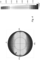
- Fig. 6 shows the illumination pattern on the unfolded cylinder, wherein the portion of the cylinder between -180 and -100 degrees and between 120 and 180 degrees is illuminated by the lighting device. The illumination pattern is clearly visible on the illuminated portion.
- Fig. 7 depicts a lighting arrangement 302 comprising a plurality of first light sources 309 and a plurality of second light sources 309'.
- the lighting arrangement 302 further comprises four beam-shaping optical elements 310, each beam-shaping optical element being assigned to a light source 309, 309'.
- the modulating optical element 307 in the form of an absorbing grid is arranged on the cover plate 308. It should be noted that the pattern of the modulating optical element is selected such that the plurality of first light sources 309 is aligned with an opening in the grid, and the plurality of second light sources is aligned with a cross in the grid. Therefore, the plurality of first light sources and the plurality of second light sources will provide two distinctly different illumination patterns. When the first and the second light sources are operated individually, the lighting arrangement may dynamically switch between the two patterns or be in a state where both patterns are on, thus providing a reduced contrast.
- Figs. 8 and 9 illustrate the intensity and illuminance distribution provided by a lighting device when the plurality of second light sources is operating.
- the dark shadow is cast by a cylinder having a longitudinal extension of 400 cm and arranged such that the longitudinal extension of the cylinder is perpendicular to the target surface.
- the cylinder thus represents a pedestrian.
- Fig. 10 shows the illumination pattern on the unfolded cylinder, wherein the portion of the cylinder between 0 and 100 degrees is illuminated by the lighting device. As may be seen in Fig. 10 , the cylinder is rather evenly illuminated.
- the intensity and illuminance distribution depicted in Figs. 11 and 12 is obtained.
- the cylinder is now positioned in a dark area of the pattern.
- the illumination pattern on the cylinder is clear even in this case.
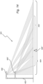
- Fig. 14 illustrates a lighting arrangement 401 comprising a first lighting device 402 arranged on a post 403 extending vertically from the ground. Further, the lighting arrangement 401 comprises a second lighting device 402' wherein the second lighting device 402' is arranged at a distance from the first lighting device 402.
- the first lighting device 402 comprises a first light source which provides a first illumination pattern on a first target surface 404. As may be seen in Fig. 14 , the first and second lighting devices 402, 402' are arranged at different heights along the vertical extension of the post 403.
- the second lighting device 402' comprises a second light source which further provides a second illumination pattern on a second target surface 404'.
- the first illumination pattern is complementary to the second illumination pattern.
- the complementary illumination patterns are chosen such that no pattern is visible on the target surface 404, but, because of the different positions of the light sources, the alignment breaks down at other heights and the pattern is visible on pedestrians. In other words, such an embodiment offers the advantage of providing a substantially invisible illumination pattern on the target surface 404, since overlapping complementary illumination patterns will provide an impression of an even illuminance.
- the illumination pattern will still be perceivable, thus increasing visibility.
Landscapes
- Engineering & Computer Science (AREA)
- General Engineering & Computer Science (AREA)
- Non-Portable Lighting Devices Or Systems Thereof (AREA)
Claims (13)
- Beleuchtungsanordnung (1) für eine Außenbeleuchtung, wobei die Beleuchtungsanordnung umfasst:eine erste Lichtquelle zum Aussenden eines ersten Lichts, wobei die erste Lichtquelle in einer ersten Beleuchtungsvorrichtung (402) angeordnet ist;eine zweite Lichtquelle zum Aussenden eines zweiten Lichts, wobei die zweite Lichtquelle in einer zweiten Beleuchtungsvorrichtung (402') angeordnet ist;ein erstes modulierendes optisches Element (7) zum Umwandeln des ersten Lichts in ein moduliertes erstes Licht, das ein erstes Beleuchtungsmuster auf einer ersten Zieloberfläche (4') bereitstellt, undein zweites modulierendes optisches Element zum Umwandeln des zweiten Lichts in ein moduliertes zweites Licht, das ein zweites Beleuchtungsmuster auf einer zweiten Zieloberfläche (4") bereitstellt,wobei die zweite Beleuchtungseinrichtung (402') mit einem Abstand von der ersten Beleuchtungseinrichtung (402) angeordnet ist, wobei der Abstand von 0,3 m bis 10 m beträgt,wobei sich die erste Zieloberfläche und die zweite Zieloberfläche mindestens teilweise überlappen,wobei jedes des ersten und des zweiten Beleuchtungsmusters eine Folge abwechselnder Beleuchtungsstärkespitzen umfasst; undwobei das erste Beleuchtungsmuster im Wesentlichen komplementär zu dem zweiten Beleuchtungsmuster ist.
- Beleuchtungsanordnung (401) nach Anspruch 1, wobei die Beleuchtungsanordnung (401) ferner mindestens ein Stützelement (403) zum Stützen der ersten und der zweiten Beleuchtungsvorrichtung (402, 402') umfasst.
- Beleuchtungsanordnung (401) nach Anspruch 2, wobei die Beleuchtungsanordnung (401) ein Stützelement (403), das eine vertikale Ausdehnung aufweist, umfasst, und wobei die erste und die zweite Beleuchtungsvorrichtung (402, 402') mit einem Abstand voneinander entlang der vertikalen Ausdehnung des Stützelements angeordnet sind.
- Beleuchtungsanordnung (401) nach Anspruch 3, wobei der Abstand zwischen der ersten und der zweiten Beleuchtungsvorrichtung von 0,5 m bis 2 m beträgt.
- Beleuchtungsanordnung (401) nach einem der vorstehenden Ansprüche, wobei die Beleuchtungsanordnung ein erstes und ein zweites Stützelement umfasst, die mit einem Abstand voneinander angeordnet sind, wobei die erste Beleuchtungsvorrichtung auf dem ersten Stützelement angeordnet ist, und wobei die zweite Beleuchtungsvorrichtung auf dem zweiten Stützelement angeordnet ist.
- Beleuchtungsanordnung (1) nach Anspruch 5, wobei der Abstand zwischen dem ersten und dem zweiten Stützelement von 5 m bis 10 m beträgt.
- Beleuchtungsanordnung (1) nach einem der vorstehenden Ansprüche, wobei die Beleuchtungsanordnung (1) ferner mindestens ein strahlformendes optisches Element (310) zum Formen des ersten und/oder des zweiten Lichts, das durch die erste und/oder die zweite Lichtquelle (309, 309') ausgesendet wird, in einen Lichtstrahl, umfasst.
- Beleuchtungsanordnung (1) nach Anspruch 7, wobei das modulierende optische Element (307) auf dem mindestens einen strahlformenden optischen Element (309) angeordnet ist.
- Beleuchtungsanordnung (1) nach einem der vorstehenden Ansprüche, wobei die Beleuchtungsanordnung ferner eine Abdeckplatte (308) umfasst, die angeordnet ist, um mindestens eine der ersten und der zweiten Lichtquelle (309, 309') abzudecken.
- Beleuchtungsanordnung (1) nach Anspruch 9, wobei das modulierende optische Element (307) auf der Abdeckplatte (308) angeordnet ist.
- Beleuchtungsanordnung (1) nach einem der vorstehenden Ansprüche, wobei das modulierende optische Element (307) ein Muster ist, das dem ersten Beleuchtungsmuster auf der ersten Zieloberfläche und/oder dem zweiten Beleuchtungsmuster auf der zweiten Zieloberfläche entspricht.
- Beleuchtungsanordnung (1) nach einem der vorstehenden Ansprüche, wobei das erste und/oder das zweite Beleuchtungsmuster ein dynamisches Muster ist.
- Beleuchtungsanordnung (1) nach einem der vorstehenden Ansprüche, wobei die Beleuchtungsanordnung eine Steuereinheit zum individuellen Steuern der ersten und der zweiten Lichtquelle (309, 309') umfasst.
Applications Claiming Priority (2)
| Application Number | Priority Date | Filing Date | Title |
|---|---|---|---|
| EP21184503 | 2021-07-08 | ||
| PCT/EP2022/068631 WO2023280879A1 (en) | 2021-07-08 | 2022-07-05 | A lighting device providing an improved visibility |
Publications (2)
| Publication Number | Publication Date |
|---|---|
| EP4367433A1 EP4367433A1 (de) | 2024-05-15 |
| EP4367433B1 true EP4367433B1 (de) | 2025-02-12 |
Family
ID=77274649
Family Applications (1)
| Application Number | Title | Priority Date | Filing Date |
|---|---|---|---|
| EP22747633.0A Active EP4367433B1 (de) | 2021-07-08 | 2022-07-05 | Beleuchtungsvorrichtung für verbesserte sichtbarkeit |
Country Status (4)
| Country | Link |
|---|---|
| US (1) | US12276401B2 (de) |
| EP (1) | EP4367433B1 (de) |
| CN (1) | CN117677793A (de) |
| WO (1) | WO2023280879A1 (de) |
Families Citing this family (1)
| Publication number | Priority date | Publication date | Assignee | Title |
|---|---|---|---|---|
| TWI852758B (zh) * | 2023-09-07 | 2024-08-11 | 晶亮電工股份有限公司 | 用於照明行人穿越道的照明裝置 |
Family Cites Families (12)
| Publication number | Priority date | Publication date | Assignee | Title |
|---|---|---|---|---|
| JPH05109305A (ja) | 1991-10-14 | 1993-04-30 | Nissan Motor Co Ltd | 光色可変照明装置 |
| JP3498290B1 (ja) * | 2002-12-19 | 2004-02-16 | 俊二 岸村 | 白色led照明装置 |
| US8136969B2 (en) | 2005-07-12 | 2012-03-20 | Burkett Karl A | Variable lighting system for optimizing night visibility |
| JP4745184B2 (ja) * | 2006-10-03 | 2011-08-10 | スタンレー電気株式会社 | 照明装置 |
| US7731383B2 (en) * | 2007-02-02 | 2010-06-08 | Inovus Solar, Inc. | Solar-powered light pole and LED light fixture |
| US20110163334A1 (en) | 2008-09-16 | 2011-07-07 | Koninklijke Philips Electronics N.V. | Colour mixing method for consistent colour quality |
| US8308318B2 (en) * | 2009-05-01 | 2012-11-13 | Lighting Science Group Corporation | Sustainable outdoor lighting system |
| GB2506417A (en) * | 2012-09-28 | 2014-04-02 | Wirefield Ltd | LED lighting unit |
| EP3434517B1 (de) | 2014-03-03 | 2023-04-05 | Koito Manufacturing Co., Ltd. | Fahrzeugscheinwerfer und fahrzeugscheinwerfersteuerungsverfahren |
| DE102016006390A1 (de) | 2016-05-24 | 2017-11-30 | Audi Ag | Beleuchtungseinrichtung für ein Kraftfahrzeug zur Erhöhung der Erkennbarkeit eines Hindernisses |
| US11097653B2 (en) | 2017-01-20 | 2021-08-24 | Koito Manufacturing Co., Ltd. | Vehicle lamp system, vehicle lamp control device and vehicle lamp control method |
| DE102017119394A1 (de) | 2017-08-28 | 2019-02-28 | HELLA GmbH & Co. KGaA | Verfahren zur Ansteuerung mindestens eines Lichtmoduls einer Leuchteinheit eines Fahrzeugs, Leuchteinheit, Computerprogrammprodukt und computerlesbares Medium |
-
2022
- 2022-07-05 EP EP22747633.0A patent/EP4367433B1/de active Active
- 2022-07-05 WO PCT/EP2022/068631 patent/WO2023280879A1/en not_active Ceased
- 2022-07-05 US US18/576,141 patent/US12276401B2/en active Active
- 2022-07-05 CN CN202280048466.1A patent/CN117677793A/zh not_active Withdrawn
Also Published As
| Publication number | Publication date |
|---|---|
| US12276401B2 (en) | 2025-04-15 |
| US20250093016A1 (en) | 2025-03-20 |
| CN117677793A (zh) | 2024-03-08 |
| EP4367433A1 (de) | 2024-05-15 |
| WO2023280879A1 (en) | 2023-01-12 |
Similar Documents
| Publication | Publication Date | Title |
|---|---|---|
| US20240357722A1 (en) | System and method for driving and controlling light sources | |
| US8007127B2 (en) | Lens for LED outdoor lamp, and its applied road lamp, security lamp, tunnel lamp, park lamp, guard lamp, industrial flood lamp, and outdoor lamp | |
| RU2431774C2 (ru) | Прожектор с дифракционным микрорельефом для системы наблюдения | |
| US20080216367A1 (en) | Road-Marking System | |
| WO2008050850A1 (en) | Outdoor illuminating device and illuminating method | |
| FI122000B (fi) | Valaisinlaite ja järjestelmä liikenneväylän risteyskohdan turvallisuuden parantamiseksi | |
| KR101406782B1 (ko) | 도로경계석 | |
| KR20210122474A (ko) | 입체효과 고보이미지를 표시하는 조명 장치 | |
| EP4367433B1 (de) | Beleuchtungsvorrichtung für verbesserte sichtbarkeit | |
| KR102508372B1 (ko) | 솔라셀이 장착된 도로표지병 | |
| JP4099403B2 (ja) | 自発光視線誘導標 | |
| KR101158243B1 (ko) | Led를 이용한 도로 표지병 | |
| CA2584245C (en) | Device and method of optical signaling for road or traffic lanes, specifically in low visibility conditions | |
| KR101412035B1 (ko) | 조명 장치 | |
| EP3640532B1 (de) | Linsenabdeckung und led-beleuchtungsvorrichtung damit | |
| EP2803911B1 (de) | LED-Beleuchtung mit verbesserter Lichtverteilung | |
| KR20130039899A (ko) | 광섬유를 사용하여 다방향으로 빛을 발산하는 도로표지병 | |
| KR101407346B1 (ko) | 횡단보도 조명장치 | |
| TWI852758B (zh) | 用於照明行人穿越道的照明裝置 | |
| RU2771841C1 (ru) | Система предупреждения участников дорожного движения о нахождении пешеходов на пешеходном переходе или вблизи него | |
| KR20250127899A (ko) | 솔라패널 상부 배치형 교통표지판 | |
| KR20240066667A (ko) | 3차원 입체효과를 표시하는 광고용 조명 장치 | |
| KR20250171811A (ko) | 교통체계에 따르는 신호제어상황에 연계하는 차량유도 시스템 및 방법 | |
| JP3869422B2 (ja) | 標識体及び標識体の設置構造 | |
| O'Flaherty | Road lighting |
Legal Events
| Date | Code | Title | Description |
|---|---|---|---|
| STAA | Information on the status of an ep patent application or granted ep patent |
Free format text: STATUS: UNKNOWN |
|
| STAA | Information on the status of an ep patent application or granted ep patent |
Free format text: STATUS: THE INTERNATIONAL PUBLICATION HAS BEEN MADE |
|
| PUAI | Public reference made under article 153(3) epc to a published international application that has entered the european phase |
Free format text: ORIGINAL CODE: 0009012 |
|
| STAA | Information on the status of an ep patent application or granted ep patent |
Free format text: STATUS: REQUEST FOR EXAMINATION WAS MADE |
|
| 17P | Request for examination filed |
Effective date: 20240208 |
|
| AK | Designated contracting states |
Kind code of ref document: A1 Designated state(s): AL AT BE BG CH CY CZ DE DK EE ES FI FR GB GR HR HU IE IS IT LI LT LU LV MC MK MT NL NO PL PT RO RS SE SI SK SM TR |
|
| GRAP | Despatch of communication of intention to grant a patent |
Free format text: ORIGINAL CODE: EPIDOSNIGR1 |
|
| STAA | Information on the status of an ep patent application or granted ep patent |
Free format text: STATUS: GRANT OF PATENT IS INTENDED |
|
| DAV | Request for validation of the european patent (deleted) | ||
| DAX | Request for extension of the european patent (deleted) | ||
| INTG | Intention to grant announced |
Effective date: 20240912 |
|
| GRAS | Grant fee paid |
Free format text: ORIGINAL CODE: EPIDOSNIGR3 |
|
| GRAA | (expected) grant |
Free format text: ORIGINAL CODE: 0009210 |
|
| STAA | Information on the status of an ep patent application or granted ep patent |
Free format text: STATUS: THE PATENT HAS BEEN GRANTED |
|
| AK | Designated contracting states |
Kind code of ref document: B1 Designated state(s): AL AT BE BG CH CY CZ DE DK EE ES FI FR GB GR HR HU IE IS IT LI LT LU LV MC MK MT NL NO PL PT RO RS SE SI SK SM TR |
|
| P01 | Opt-out of the competence of the unified patent court (upc) registered |
Free format text: CASE NUMBER: APP_405/2025 Effective date: 20250106 |
|
| REG | Reference to a national code |
Ref country code: GB Ref legal event code: FG4D |
|
| REG | Reference to a national code |
Ref country code: CH Ref legal event code: EP |
|
| REG | Reference to a national code |
Ref country code: DE Ref legal event code: R096 Ref document number: 602022010593 Country of ref document: DE |
|
| REG | Reference to a national code |
Ref country code: IE Ref legal event code: FG4D |
|
| REG | Reference to a national code |
Ref country code: NL Ref legal event code: MP Effective date: 20250212 |
|
| PG25 | Lapsed in a contracting state [announced via postgrant information from national office to epo] |
Ref country code: RS Free format text: LAPSE BECAUSE OF FAILURE TO SUBMIT A TRANSLATION OF THE DESCRIPTION OR TO PAY THE FEE WITHIN THE PRESCRIBED TIME-LIMIT Effective date: 20250512 |
|
| PG25 | Lapsed in a contracting state [announced via postgrant information from national office to epo] |
Ref country code: FI Free format text: LAPSE BECAUSE OF FAILURE TO SUBMIT A TRANSLATION OF THE DESCRIPTION OR TO PAY THE FEE WITHIN THE PRESCRIBED TIME-LIMIT Effective date: 20250212 |
|
| PG25 | Lapsed in a contracting state [announced via postgrant information from national office to epo] |
Ref country code: PL Free format text: LAPSE BECAUSE OF FAILURE TO SUBMIT A TRANSLATION OF THE DESCRIPTION OR TO PAY THE FEE WITHIN THE PRESCRIBED TIME-LIMIT Effective date: 20250212 |
|
| PG25 | Lapsed in a contracting state [announced via postgrant information from national office to epo] |
Ref country code: ES Free format text: LAPSE BECAUSE OF FAILURE TO SUBMIT A TRANSLATION OF THE DESCRIPTION OR TO PAY THE FEE WITHIN THE PRESCRIBED TIME-LIMIT Effective date: 20250212 |
|
| REG | Reference to a national code |
Ref country code: LT Ref legal event code: MG9D |
|
| PG25 | Lapsed in a contracting state [announced via postgrant information from national office to epo] |
Ref country code: NO Free format text: LAPSE BECAUSE OF FAILURE TO SUBMIT A TRANSLATION OF THE DESCRIPTION OR TO PAY THE FEE WITHIN THE PRESCRIBED TIME-LIMIT Effective date: 20250512 Ref country code: IS Free format text: LAPSE BECAUSE OF FAILURE TO SUBMIT A TRANSLATION OF THE DESCRIPTION OR TO PAY THE FEE WITHIN THE PRESCRIBED TIME-LIMIT Effective date: 20250612 |
|
| PG25 | Lapsed in a contracting state [announced via postgrant information from national office to epo] |
Ref country code: NL Free format text: LAPSE BECAUSE OF FAILURE TO SUBMIT A TRANSLATION OF THE DESCRIPTION OR TO PAY THE FEE WITHIN THE PRESCRIBED TIME-LIMIT Effective date: 20250212 |
|
| PG25 | Lapsed in a contracting state [announced via postgrant information from national office to epo] |
Ref country code: HR Free format text: LAPSE BECAUSE OF FAILURE TO SUBMIT A TRANSLATION OF THE DESCRIPTION OR TO PAY THE FEE WITHIN THE PRESCRIBED TIME-LIMIT Effective date: 20250212 |
|
| PG25 | Lapsed in a contracting state [announced via postgrant information from national office to epo] |
Ref country code: PT Free format text: LAPSE BECAUSE OF FAILURE TO SUBMIT A TRANSLATION OF THE DESCRIPTION OR TO PAY THE FEE WITHIN THE PRESCRIBED TIME-LIMIT Effective date: 20250612 Ref country code: LV Free format text: LAPSE BECAUSE OF FAILURE TO SUBMIT A TRANSLATION OF THE DESCRIPTION OR TO PAY THE FEE WITHIN THE PRESCRIBED TIME-LIMIT Effective date: 20250212 |
|
| PG25 | Lapsed in a contracting state [announced via postgrant information from national office to epo] |
Ref country code: GR Free format text: LAPSE BECAUSE OF FAILURE TO SUBMIT A TRANSLATION OF THE DESCRIPTION OR TO PAY THE FEE WITHIN THE PRESCRIBED TIME-LIMIT Effective date: 20250513 Ref country code: BG Free format text: LAPSE BECAUSE OF FAILURE TO SUBMIT A TRANSLATION OF THE DESCRIPTION OR TO PAY THE FEE WITHIN THE PRESCRIBED TIME-LIMIT Effective date: 20250212 |
|
| PG25 | Lapsed in a contracting state [announced via postgrant information from national office to epo] |
Ref country code: SE Free format text: LAPSE BECAUSE OF FAILURE TO SUBMIT A TRANSLATION OF THE DESCRIPTION OR TO PAY THE FEE WITHIN THE PRESCRIBED TIME-LIMIT Effective date: 20250212 |
|
| PG25 | Lapsed in a contracting state [announced via postgrant information from national office to epo] |
Ref country code: SM Free format text: LAPSE BECAUSE OF FAILURE TO SUBMIT A TRANSLATION OF THE DESCRIPTION OR TO PAY THE FEE WITHIN THE PRESCRIBED TIME-LIMIT Effective date: 20250212 |
|
| PG25 | Lapsed in a contracting state [announced via postgrant information from national office to epo] |
Ref country code: DK Free format text: LAPSE BECAUSE OF FAILURE TO SUBMIT A TRANSLATION OF THE DESCRIPTION OR TO PAY THE FEE WITHIN THE PRESCRIBED TIME-LIMIT Effective date: 20250212 |
|
| PGFP | Annual fee paid to national office [announced via postgrant information from national office to epo] |
Ref country code: DE Payment date: 20250926 Year of fee payment: 4 |
|
| PG25 | Lapsed in a contracting state [announced via postgrant information from national office to epo] |
Ref country code: IT Free format text: LAPSE BECAUSE OF FAILURE TO SUBMIT A TRANSLATION OF THE DESCRIPTION OR TO PAY THE FEE WITHIN THE PRESCRIBED TIME-LIMIT Effective date: 20250212 |
|
| PG25 | Lapsed in a contracting state [announced via postgrant information from national office to epo] |
Ref country code: AT Free format text: LAPSE BECAUSE OF FAILURE TO SUBMIT A TRANSLATION OF THE DESCRIPTION OR TO PAY THE FEE WITHIN THE PRESCRIBED TIME-LIMIT Effective date: 20250212 |
|
| PGFP | Annual fee paid to national office [announced via postgrant information from national office to epo] |
Ref country code: FR Payment date: 20250725 Year of fee payment: 4 |
|
| PG25 | Lapsed in a contracting state [announced via postgrant information from national office to epo] |
Ref country code: EE Free format text: LAPSE BECAUSE OF FAILURE TO SUBMIT A TRANSLATION OF THE DESCRIPTION OR TO PAY THE FEE WITHIN THE PRESCRIBED TIME-LIMIT Effective date: 20250212 Ref country code: CZ Free format text: LAPSE BECAUSE OF FAILURE TO SUBMIT A TRANSLATION OF THE DESCRIPTION OR TO PAY THE FEE WITHIN THE PRESCRIBED TIME-LIMIT Effective date: 20250212 |
|
| PG25 | Lapsed in a contracting state [announced via postgrant information from national office to epo] |
Ref country code: RO Free format text: LAPSE BECAUSE OF FAILURE TO SUBMIT A TRANSLATION OF THE DESCRIPTION OR TO PAY THE FEE WITHIN THE PRESCRIBED TIME-LIMIT Effective date: 20250212 |
|
| PG25 | Lapsed in a contracting state [announced via postgrant information from national office to epo] |
Ref country code: SK Free format text: LAPSE BECAUSE OF FAILURE TO SUBMIT A TRANSLATION OF THE DESCRIPTION OR TO PAY THE FEE WITHIN THE PRESCRIBED TIME-LIMIT Effective date: 20250212 |
|
| REG | Reference to a national code |
Ref country code: DE Ref legal event code: R097 Ref document number: 602022010593 Country of ref document: DE |
|
| PLBE | No opposition filed within time limit |
Free format text: ORIGINAL CODE: 0009261 |
|
| STAA | Information on the status of an ep patent application or granted ep patent |
Free format text: STATUS: NO OPPOSITION FILED WITHIN TIME LIMIT |
|
| 26N | No opposition filed |
Effective date: 20251113 |