EP4366151A1 - Webmaschine und verfahren zur steuerung davon - Google Patents
Webmaschine und verfahren zur steuerung davon Download PDFInfo
- Publication number
- EP4366151A1 EP4366151A1 EP22833038.7A EP22833038A EP4366151A1 EP 4366151 A1 EP4366151 A1 EP 4366151A1 EP 22833038 A EP22833038 A EP 22833038A EP 4366151 A1 EP4366151 A1 EP 4366151A1
- Authority
- EP
- European Patent Office
- Prior art keywords
- circuit
- phase
- power supply
- control signal
- cut
- Prior art date
- Legal status (The legal status is an assumption and is not a legal conclusion. Google has not performed a legal analysis and makes no representation as to the accuracy of the status listed.)
- Pending
Links
- 238000000034 method Methods 0.000 title claims abstract description 28
- 238000001514 detection method Methods 0.000 claims description 21
- 230000007246 mechanism Effects 0.000 claims description 19
- 230000005291 magnetic effect Effects 0.000 claims description 17
- 239000003302 ferromagnetic material Substances 0.000 claims description 4
- 230000004913 activation Effects 0.000 claims description 2
- 230000003213 activating effect Effects 0.000 claims 2
- 238000010586 diagram Methods 0.000 description 16
- 230000008878 coupling Effects 0.000 description 11
- 238000010168 coupling process Methods 0.000 description 11
- 238000005859 coupling reaction Methods 0.000 description 11
- XEEYBQQBJWHFJM-UHFFFAOYSA-N Iron Chemical compound [Fe] XEEYBQQBJWHFJM-UHFFFAOYSA-N 0.000 description 4
- 230000005484 gravity Effects 0.000 description 3
- 230000005415 magnetization Effects 0.000 description 3
- 230000010287 polarization Effects 0.000 description 3
- 229910052742 iron Inorganic materials 0.000 description 2
- 230000008569 process Effects 0.000 description 2
- 238000004804 winding Methods 0.000 description 2
- 239000003990 capacitor Substances 0.000 description 1
- 230000007423 decrease Effects 0.000 description 1
- 230000000694 effects Effects 0.000 description 1
- 239000004744 fabric Substances 0.000 description 1
- 238000012986 modification Methods 0.000 description 1
- 230000004048 modification Effects 0.000 description 1
- 230000000630 rising effect Effects 0.000 description 1
- 239000011435 rock Substances 0.000 description 1
- 238000000926 separation method Methods 0.000 description 1
- 238000006467 substitution reaction Methods 0.000 description 1
- 238000009941 weaving Methods 0.000 description 1
Images




Classifications
-
- D—TEXTILES; PAPER
- D03—WEAVING
- D03D—WOVEN FABRICS; METHODS OF WEAVING; LOOMS
- D03D51/00—Driving, starting, or stopping arrangements; Automatic stop motions
- D03D51/06—Driving, starting, or stopping arrangements; Automatic stop motions using particular methods of stopping
-
- H—ELECTRICITY
- H02—GENERATION; CONVERSION OR DISTRIBUTION OF ELECTRIC POWER
- H02P—CONTROL OR REGULATION OF ELECTRIC MOTORS, ELECTRIC GENERATORS OR DYNAMO-ELECTRIC CONVERTERS; CONTROLLING TRANSFORMERS, REACTORS OR CHOKE COILS
- H02P29/00—Arrangements for regulating or controlling electric motors, appropriate for both AC and DC motors
- H02P29/02—Providing protection against overload without automatic interruption of supply
- H02P29/024—Detecting a fault condition, e.g. short circuit, locked rotor, open circuit or loss of load
- H02P29/025—Detecting a fault condition, e.g. short circuit, locked rotor, open circuit or loss of load the fault being a power interruption
-
- H—ELECTRICITY
- H02—GENERATION; CONVERSION OR DISTRIBUTION OF ELECTRIC POWER
- H02P—CONTROL OR REGULATION OF ELECTRIC MOTORS, ELECTRIC GENERATORS OR DYNAMO-ELECTRIC CONVERTERS; CONTROLLING TRANSFORMERS, REACTORS OR CHOKE COILS
- H02P3/00—Arrangements for stopping or slowing electric motors, generators, or dynamo-electric converters
- H02P3/06—Arrangements for stopping or slowing electric motors, generators, or dynamo-electric converters for stopping or slowing an individual dynamo-electric motor or dynamo-electric converter
- H02P3/18—Arrangements for stopping or slowing electric motors, generators, or dynamo-electric converters for stopping or slowing an individual dynamo-electric motor or dynamo-electric converter for stopping or slowing an AC motor
- H02P3/22—Arrangements for stopping or slowing electric motors, generators, or dynamo-electric converters for stopping or slowing an individual dynamo-electric motor or dynamo-electric converter for stopping or slowing an AC motor by short-circuit or resistive braking
-
- H—ELECTRICITY
- H02—GENERATION; CONVERSION OR DISTRIBUTION OF ELECTRIC POWER
- H02P—CONTROL OR REGULATION OF ELECTRIC MOTORS, ELECTRIC GENERATORS OR DYNAMO-ELECTRIC CONVERTERS; CONTROLLING TRANSFORMERS, REACTORS OR CHOKE COILS
- H02P3/00—Arrangements for stopping or slowing electric motors, generators, or dynamo-electric converters
- H02P3/06—Arrangements for stopping or slowing electric motors, generators, or dynamo-electric converters for stopping or slowing an individual dynamo-electric motor or dynamo-electric converter
- H02P3/18—Arrangements for stopping or slowing electric motors, generators, or dynamo-electric converters for stopping or slowing an individual dynamo-electric motor or dynamo-electric converter for stopping or slowing an AC motor
- H02P3/26—Arrangements for stopping or slowing electric motors, generators, or dynamo-electric converters for stopping or slowing an individual dynamo-electric motor or dynamo-electric converter for stopping or slowing an AC motor by combined electrical and mechanical braking
Definitions
- An embodiment relates to a loom and a control method for the same.
- a loom including an electric shedding device.
- the electric shedding device is provided with a plurality of heald frames.
- the pattern of cloth or threads can be determined by the kind of warp setting in the heald frame of the electric shedding device and timings of the up-and-down motion of the heald frame.
- a servomotor is used for moving the heald frame up and down.
- an electromagnetic brake or a dynamic brake is used for stopping the up-and-down motion of the heald frame and holding the heald frame.
- the electromagnetic brake is configured to be applied when power is lost.
- the brake automatically works to mechanically fixe a motor shaft.
- the electromagnetic brake may work despite a situation where the motor is rotating at a high speed. Therefore, the electromagnetic brake is easy to deteriorate because of, for example, wear of a brake contact surface.
- an electromagnetic brake has to be provided for every motor, which results in increase in the loom size and the cost.
- the dynamic brake is a brake that converts rotational energy of the motor to thermal energy by means of an electrical switch to decelerate or stop the rotation of the motor. Therefore, when power is cut off, it is likely that the dynamic brake cannot brake the motor and the heald frame suddenly falls. For example, there is a case where the loom is stopped and an operator works under the heald frame. In this case, when power is cut off in the middle of the work, the heald frame may suddenly fall and put the operator at risk.
- a loom and a control method therefor are provided which are inexpensive and can prevent sudden fall of a heald frame even when power is lost.
- a loom comprises a heald frame; a driving portion configured to move the heald frame up and down; a power supply circuit configured to supply power to the driving portion; a switch circuit connected between a plurality of wires transferring the power from the power supply circuit to the driving portion, and configured to short-circuit the wires to each other or open the wires in accordance with a control signal; and a control circuit configured to supply the control signal to the switch circuit to control the switch circuit, wherein after cut-off of power supply from the power supply circuit to the driving portion, the switch circuit holds a short-circuit state or an open state based on the last control signal received before the cut-off of power supply.
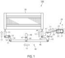
- FIG. 1 is a diagram illustrating a configuration example of a loom 100 according to a first embodiment.
- the loom 100 mainly includes a driving portion 20, a heald frame 30, and a coupling portion 40 that couples the driving portion 20 and the heald frame 30 to each other.
- the driving portion 20 includes a motor 21, a rotation shaft 22, and a crank arm 23.
- the motor 21 rotates the crank arm fixed to the rotation shaft to cause a shedding lever 41 that is provided on an oscillating shaft 42 to be able to turn around the oscillating shaft 42 to oscillate (rock or swing) in the direction of an arrow Y1 via a coupling rod 24.
- the shedding lever 41 is coupled at one arm 45 to the lower end of a lifting rod 44 coupled to the heald frame 30 and at the other arm 43 to the right end of a horizontal rod 46 arranged below the heald frame 30.
- An auxiliary lever 48 is provided above the horizontal rod 46 to extend in a direction perpendicular to the horizontal rod 46 and is supported by a shaft 47 to be able to oscillate.
- the left end of the horizontal rod 46 is coupled to one arm 51 of an oscillating lever 54 which is provided on an oscillating shaft 53 arranged below the heald frame 30 to be rotatable around the oscillating shaft 53.
- the other arm 52 of the oscillating lever 54 is coupled to the lower end of a lifting rod 55 coupled to the heald frame 30.
- the shedding lever 41 moves the heald frame 30 up and down via the arm 45, the lifting rod 44, the arm 43, the horizontal rod 46, the oscillating lever 54, and the lifting rod 55 to perform shedding of warp. Therefore, the coupling portion 40 is configured by the coupling rod 24, the shedding lever 41, the lifting rod 44, the horizontal rod 46, the oscillating lever 54, and the lifting rod 55. As the coupling portion 40 is configured in this manner, the linear motion of the coupling rod 24 in the direction of the arrow the Y1 is converted to a linear motion of the horizontal rod 46 in the direction of an arrow Y2. The linear motion of the horizontal rod 46 in the direction of the arrow Y2 is then converted to an up-and-down motion of the lifting rod 44 and the lifting rod 55 in the direction of an arrow Y3. Accordingly, the heald frame 30 is moved up and down.
- FIG. 2 is a block diagram illustrating a detailed configuration of the driving portion 20 described above.
- FIG. 2 is a block diagram illustrating a region A in FIG. 1 in an enlarged manner.
- the driving portion 20 includes the motor 21, the rotation shaft 22, and the crank arm 23 described above and further includes a decelerator 25, a brake mechanism 26, and a crank rotary table 27.
- the decelerator 25 is provided between the motor 21 and the crank rotary table 27.
- the decelerator 25 rotates in the direction of an arrow Y5 to reduce the rotational speed of the motor 21 and output motive power (driving power) of the motor 21 to the crank rotary table 27. Therefore, the decelerator 25 is joined to (contacts with) the crank rotary table 27.
- the crank rotary table 27 outputs the motive power of the motor 21 output from the decelerator 25, to the crank arm 23. Specifically, the crank rotary table 27 rotates about the rotation shaft 22 in the direction of an arrow Y4 to output the motive power of the motor 21 to the crank arm 23.
- the direction of the arrow Y4 is opposite to the direction of an arrow Y5 that is the direction of rotation of the decelerator 25.
- the motive power of the motor 21 is output to the coupling rod 24 via the decelerator 25, the crank rotary table 27, and the crank arm 23.
- the coupling rod 24 performs the linear motion in the direction of the arrow Y1.
- the rotation shaft 22, the crank arm 23, the decelerator 25, and the crank rotary table 27 configure a driving mechanism.
- the driving portion 20 moves the heald frame 30 up and down via the driving mechanism, the coupling rod 24, the horizontal rod 46, the lifting rod 44, and the lifting rod 55 in this manner.
- the motor 21 causes the driving mechanism to operate.
- the brake mechanism 26 controls the motive power of the motor 21. Specifically, the brake mechanism 26 reduces the number of rotations of the motor 21 or stops the motor 21.
- the brake mechanism 26 includes, for example, an electromagnetic brake or a dynamic brake.
- the electromagnetic brake is a brake that mechanically fixes the motor shaft of the motor 21.
- the dynamic brake is a brake applicable in a case where a magnet is used in a stator part or a rotor part of the motor 21.
- the dynamic brake converts rotational energy of the motor 21 to thermal energy by using an induced voltage generated by rotation of the motor 21, thereby decelerating or stopping the rotation of the motor 21.
- FIG. 3 is a block diagram illustrating a configuration of the motor 21, the brake mechanism 26, and the periphery of the motor 21 and the brake mechanism 26.
- FIG. 3 is a block diagram illustrating a region B in FIG. 2 in an enlarged manner.
- the motor 21 includes a servomotor 211 and an encoder 212.
- a three-phase PM (Permanent Magnet) motor may be used as the servomotor 211.
- the three-phase PM motor uses a magnet in a stator part or a rotor part. Therefore, a dynamic brake can be applied to the brake mechanism 26 associated with this motor 21.
- the servomotor 211 is a three-phase PM motor having a U phase, a V phase, and a W phase. Specifically, the servomotor 211 is a three-phase PM motor having the U phase, the V phase, and the W phase in which an induced voltage of each phase has a phase difference from an induced voltage of another phase.
- the encoder 212 detects the number of rotations of the servomotor 211.
- the encoder 212 may include a position sensor, and may further detect the position and the rotational speed of the servomotor 211.
- a power source 223 supplies power to the motor 21 (the driving portion 20).
- the power source 223 is, for example, a commercial AC power supply.
- a transistor bridge circuit 221 as a power supply circuit is connected to the motor 21 via wires Cu, Cv, and Cw, receives power supply from the power source 223, and controls the position, the number of rotations, and the like of the motor 21.
- the transistor bridge circuit 221 is included in an inverter, for example.
- a cut-off detection circuit 224 detects cut-off of power supply from the power source 223 to the transistor bridge circuit 221 and transmits a cut-off detection signal to a control power source 225 and a control circuit 226.
- the control power source 225 temporarily supplies power to the control circuit 226 and the brake mechanism 26 also after the cut-off of power supply from the power source 223 to the transistor bridge circuit 221.
- the control circuit 226 and the brake mechanism 26 can continue to effectively operate due to power supply from the control power source 225, also after the cut-off of power supply to the transistor bridge circuit 221.
- the control power source 225 is a storage battery or a capacitor element having a power-supply voltage of several volts to tens of volts (from about 3 volts to about 24 volts), for example.
- the control circuit 226 supplies a control signal to switch circuits 260A and 260B to control the switch circuits 260A and 260B.
- the control circuit 226 is implemented by, for example, a CPU (Central Processing Unit) provided with a program supplying the control signal or a logic circuit such as a PLC (Programmable Logic Controller).
- the control signal includes a first control signal and a second control signal.
- the first control signal is transmitted from the control circuit 226 to the switch circuits 260A and 260B and places the switch circuits 260 A and 260B in a short-circuit state.
- the second control signal is transmitted from the control circuit 226 to the switch circuits 260A and 260B similarly, but places the switch circuits 260A and 260B in an open state.
- the control circuit 226 is connected to the switch circuit 260A via wires C1 and C2 and drive circuits 262A and to the switch circuit 260B via wires C3 and C4 and drive circuits 262B, for example.
- the control circuit 226 transmits the first control signal to the switch circuit 260A via the wire C1 and one of the drive circuits 262A and transmits the second control signal to the switch circuit 260A via the wire C2 and the other drive circuit 262A.
- the control circuit 226 transmits the first control signal to the switch circuit 260B via the wire C3 and one of the drive circuits 262B and transmits the second control signal to the switch circuit 260B via the wire C4 and the other drive circuit 262B.
- the brake mechanism 26 includes the switch circuits 260A and 260B and the drive circuits 262A and 262B.
- the switch circuits 260A and 260B are contact holding relay switch circuits respectively including contact holding relay switches 261A and 261B.
- the switch circuits 260A and 260B may have the same configuration as each other.
- the brake mechanism 26 is connected to the wires Cu, Cv, and Cw between the transistor bridge circuit 221 and the motor 21.
- the switch circuits 260A and 260B are respectively connected between the wires Cu, Cv and between the wires Cv, Cw transferring power from the transistor bridge circuit 221 to the motor 21 and can short-circuit or open the wires Cu and Cv or Cv and Cw in accordance with the first or second control signal.
- the control circuit 226 transmits the first control signal to the switch circuit 260A to short-circuit the switch circuit 260A, for example, the wires Cu and Cv are short-circuited to each other.
- the control circuit 226 transmits the first control signal to the switch circuit 260B to short-circuit the switch circuit 260B, the wires Cv and Cw are short-circuited to each other.
- the control circuit 226 transmits the first control signal to the switch circuit 260A and the switch circuit 260B to short-circuit the switch circuit 260A and the switch circuit 260B, all the wires Cu, Cv, and Cw are short-circuited to one another.
- the control circuit 226 transmits the first control signal to the switch circuit 260A to short-circuit the switch circuit 260A, the U phase and the V phase of the servomotor 211 are short-circuited to each other.
- the control circuit 226 transmits the first control signal to the switch circuit 260B to short-circuit the switch circuit 260B, the V phase and the W phase of the servomotor 211 are short-circuited to each other.
- the control circuit 226 transmits the first control signal to the switch circuit 260A and the switch circuit 260B to short-circuit the switch circuit 260A and the switch circuit 260B, the U phase, the V phase, and the W phase of the servomotor 211 are all short-circuited to each other.
- the U phase and the V phase, the V phase and the W phase, or the U phase, the V phase, and the W phase of the servomotor 211 are short-circuited to each other, so that a short circuit is formed via resistances Ru and Rv, resistances Rv and Rw, and/or resistances Ru, Rv and Rw in the servomotor 211.
- the servomotor 211 is a three-phase PM motor having the U phase, the V phase, and the W phase in which an induced voltage of each phase has a phase difference from an induced voltage of another phase.
- a current generated by the induced voltage flows in the short circuit formed via the resistances Ru and Rv, the resistances Rv and Rw, and/or the resistances Ru, Rv and Rw in the servomotor 211.
- the current flowing in this short circuit is converted from electrical energy to thermal energy in the resistance Ru, the resistance Rv, and/or the resistance Rw. Consequently, rotational resistance is generated in the rotation of the servomotor 211, thereby decelerating or stopping the rotation of the servomotor 211.
- the switch circuit 260A or the switch circuit 260B is caused to function as a dynamic brake for the servomotor 211 by short-circuiting the corresponding wires among the wire Cu, the wire Cv, and the wire Cw. That is, the switch circuit 260A or the switch circuit 260B is caused to function as a dynamic brake for the servomotor 211 by short-circuiting the U phase and the V phase, the V phase and the W phase, or the U phase, the V phase, and the W phase of the servomotor 211 to each other.
- the switch circuit 260A and the switch circuit 260B that are two switch circuits 260 are illustrated in FIG.
- the loom 100 according to the first embodiment can also be implemented by using a single switch circuit 260. Further, the loom 100 can also be implemented by using three switch circuits. For example, an additional switch circuit may be provided between the wires Cw and Cu. This configuration enables the switch circuits to function as a dynamic brake that short-circuits not only the U phase and the V phase, the V phase and the W phase, or the U phase, the V phase, and the W phase of the servomotor 211 to each other but also the W phase and the U phase to each other.
- the drive circuits 262A and 262B are connected between the control circuit 226 and the switch circuit 260A and between the control circuit 226 and the switch circuit 260B, respectively.
- the drive circuits 262A and 262B amplify the control signal transferred via the wires C1 to C4 and transmit it to the switch circuits 260A and 260B.
- the switch circuits 260A and 260B are effectively controlled based on this control signal.
- FIG. 4 is a detailed configuration diagram of the contact holding relay switch 261A.
- the contact holding relay switch 261B has the same configuration as the contact holding relay switch 261A. Therefore, the configuration of the contact holding relay switch 261A is described here, and descriptions of the contact holding relay switch 261B are omitted.
- the contact holding relay switch 261A includes a terminal 2611, a connection piece 2612, and a coil 2613.
- the connection piece 2612 is an example of a movable connection piece.
- the terminal 2611 contains a ferromagnetic material that can easily be magnetized by a current caused to flow through the coil 2613.
- the connection piece 2612 can be moved by the magnetic force of the terminal 2611 to come into contact with the terminal 2611 or separate from the terminal 2611.
- the connection piece 2612 contains, for example, iron.
- the coil 2613 is provided to be wound around the terminal 2611 and causes the terminal 2611 to generate the magnetic force that moves the connection piece 2612 or magnetizes the terminal 2611.
- the coil 2613 includes a coil 2613A and a coil 2613B.
- the winding direction of the coil 2613A is opposite to the winding direction of the coil 2613B.
- the contact holding relay switch 261A includes a spring 2614, a support piece 2615, a motion axis 2616, and a switch terminal 2617.
- the spring 2614 is an example of a return spring.
- the spring 2614 is attached so as to separate the connection piece 2612 from the terminal 2611.
- the support piece 2615 supports the connection piece 2612.
- the motion axis 2616 couples the connection piece 2612 and the support piece 2615 to each other and serves as an axis of a contacting motion and a separating motion of the connection piece 2612.
- the switch terminal 2617 is a terminal that comes into contact with an external switch terminal S1.
- the switch circuit 260 is short-circuited or opened by this contact holding relay switch 261A.
- FIG. 5A is an explanatory diagram of the on state of the contact holding relay switch 261A.
- the switch terminal 2617 comes into contact with the external switch terminal S1, whereby the contact holding relay switch 261A is placed in an on state.
- a current I1 flows through the coil 2613A. Accordingly, a magnetic field is generated around the coil 2613A.
- the terminal 2611 is magnetized by the magnetic field generated around the coil 2613A. Since the terminal 2611 contains a ferromagnetic material, magnetic polarization (magnetization) occurs in the terminal 2611, so that the terminal 2611 serves as a magnet. Since the connection piece 2612 contains iron as described above, magnetic force is generated between the connection piece 2612 and the magnetized terminal 2611. Consequently, the terminal 2611 and the connection piece 2612 are joined to (contacts with) each other, and the switch terminal 2617 and the external switch terminal S1 are joined to (contacts with) each other, as illustrated in FIG. 5A . That is, the contact holding relay switch 261A becomes an on state.
- FIG. 5B is an explanatory diagram of the on state of the contact holding relay switch 261A after a current has been caused to flow through the coil 2613A.
- FIG. 5C is an explanatory diagram when the contact holding relay switch 261A is switched from an on state to an off state.
- a current I2 is caused to flow through the lower coil 2613B. Accordingly, a magnetic field generated around the coil 2613B by the flow of the current I2 is generated in an opposite direction to the magnetic field generated around the coil 2613A by the flow of the current I1. Therefore, magnetic polarization (magnetization) in the terminal 2611 caused by the magnetic field generated by the current I2 occurs in the opposite direction to the magnetic polarization in the terminal 2611 caused by the magnetic field generated by the current I1. The magnetic field caused by the current I2 weakens magnetization of the terminal 2611 that has been magnetized by the current I1. Accordingly, the magnetic force of the terminal 2611 decreases.
- the terminal 2611 and the connection piece 2612 separate from each other in the direction of an arrow Y6, and the switch terminal 2617 and the external switch terminal S1 separate from each other, as illustrated in FIG. 5C . That is, the contact holding relay switch 261A becomes an off state.
- the spring 2614 assists separation of the terminal 2611 and the connection piece 2612 from each other.
- the contact holding relay switch 261A is configured to be able to hold the on state also after cut-off of power supply. Therefore, once the contact holding relay switch 261A receives power supply from the control power source 225 and is placed in the on state by the first control signal after cut-off of power supply to the transistor bridge circuit 221, the contact holding relay switch 261A keeps the on state even when power supply from the control power source 225 is lost or even when the first control signal is deactivated.
- the contact holding relay switch 261A cancels the held on state and becomes an off state as illustrated in FIG. 5C .
- the contact holding relay switch 261A is placed in the off state by activation of the second control signal.
- the loom 100 can also be implemented by using the coil 2613 configured by a single coil.
- effects identical to those in FIGS. 5A , 5B , and 5C described above are obtained by making the flowing direction of the current caused to flow through the coil 2613 opposite between when the contact holding relay switch 261A is placed in an on state and when the contact holding relay switch 261A is placed in an off state.
- FIG. 6A is a flowchart for explaining a control method for the loom 100 which prevents sudden fall of the heald frame 30 when the motor 21 is stopped.
- the cut-off detection circuit 224 detects cut-off of power supply from a power source to the transistor bridge circuit 221 (Step S100). For example, the cut-off detection circuit 224 detects the cut-off of power supply from the power source to the transistor bridge circuit 221 due to occurrence of a power outage or the like.
- the control circuit 226 places transistors in the transistor bridge circuit 221 in a non-conducting state (an off state) (Step S110). If the transistors in the transistor bridge circuit 221 remain in a conducting state, a current generated in the motor 21 flows to the transistor bridge circuit 221. Therefore, an overcurrent may flow to the transistor bridge circuit 221 when the motor 21 is rotating at a high speed. Such overcurrent leads to a failure of the transistor bridge circuit 221. For this reason, the control circuit 226 places the transistors in the transistor bridge circuit 221 in a non-conducting state at Step S110.
- the control circuit 226 checks that the number of rotations of the motor 21 is a threshold or less (Step S120). Specifically, the control circuit 226 detects the number of rotations of the motor 21 by means of the encoder 212 and checks that the detected number of rotations of the motor 21 is the threshold or less. When the number of rotations of the motor 21 is equal to or larger than the threshold (No at Step S120), the control circuit 226 stands by while checking the number of rotations of the motor 21 until the number of rotations of the motor 21 becomes the threshold or less.
- the switch circuit 260A or 260B becomes the short-circuit state during high-speed rotation of the motor 21, an overcurrent may flow to the switch circuit 260A or 260B. Such an overcurrent leads to a failure of the switch circuit 260A or 260B. Therefore, the control circuit 226 places the switch circuit 260A or 260B in a short-circuit state after the number of rotations of the motor 21 becomes the threshold or less.
- the control circuit 226 transmits the first control signal that places the switch circuit 260 in the short-circuit state to the contact holding relay switch 261A or 261B via the drive circuit 262 (Step S130).
- the contact holding relay switch 261 becomes an on state, so that the corresponding wires among the wire Cu, the wire Cv, and the wire Cw of the motor 21 is short-circuited. Consequently, a short circuit is formed via the corresponding resistances among the resistance Ru, the resistance Rv, or the resistance Rw in the motor 21.
- a dynamic brake for the motor 21 becomes effective.
- FIG. 6B is a timing chart illustrating an operation of the loom 100 when the servomotor 211 of the motor 21 has been already stopped at the time of cut-off of power supply.
- the cut-off detection circuit 224 detects cut-off of power supply (t2).
- the control circuit 226 places transistors in the transistor bridge circuit 221 in an open state (an off state) (t3).
- the control power source 225 continues to supply power to the control circuit 226 and the contact holding relay switches 261A and 261B for a while also after the cut-off of power supply.
- the control circuit 226 opens the transistors in the transistor bridge circuit 221 from connection to the motor 21, checks that the number of rotations of the motor 21 becomes a threshold or less, and transmits the first control signal to the contact holding relay switch 261 (t4).
- the contact holding relay switch 261 becomes an on state upon receiving the first control signal (t5). After the contact holding relay switch 261 becomes the on state, the first control signal is deactivated (t6), and the control power source also stops supply (t7). The second control signal that places the contact holding relay switch 261 in an off state is inactive from t1 to t7.
- the loom 100 holds the on state of the contact holding relay switch 261 even when power supply from a power source is cut off.
- the loom 100 holds the short-circuit state or the open state of the switch circuit 260 based on the last control signal received before the cut-off of power supply.
- a dynamic brake for the motor 21 becomes effective even when power supply from the power source is cut off. Accordingly, when the heald frame 30 is about to fall suddenly, an induced current flows to a short circuit including the resistances Ru, Rv, and Rw in the motor 21, and the dynamic brake is applied to the motor 21. Therefore, the heald frame 30 slowly moves down by the gravity and a braking function of the dynamic brake, so that sudden fall is prevented. Consequently, for example, safety of an operator who works under the heald frame 30 can be ensured even when power supply from the power source to the transistor bridge circuit 221 is cut off.
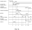
- FIG. 7A is a timing chart illustrating an operation of the loom 100 when power supply is cut off during rotation of the servomotor 211 of the motor 21.
- the cut-off detection circuit 224 detects the cut-off of power supply (t2).
- the control circuit 226 places transistors in the transistor bridge circuit 221 in an open state (an off state) (t3).
- the control power source 225 continues to supply power to the control circuit 226 and the contact holding relay switches 261A and 261B for a while also after the cut-off of power supply.
- the encoder 212 checks that the speed of rotation of the motor 21 is a threshold or less (t4), the control circuit 226 transmits the first control signal to the contact holding relay switch 261 (t5).
- the contact holding relay switch 261 becomes an on state upon receiving the first control signal (t6). After the contact holding relay switch 261 becomes the on state, the first control signal is deactivated (t7), and the control power source also stops supply (t8). The second control signal that opens the contact holding relay switch 261 is inactive from t1 to t8.
- the loom 100 holds the on state of the contact holding relay switch 261 even when power supply from a power source is cut off. In other words, after cut-off of power supply from the transistor bridge circuit 221 to the driving portion 20, the loom 100 holds the short-circuit state or the open state based on the last control signal received before the cut-off of power supply.
- a dynamic brake for the motor 21 becomes effective even when power supply from the power source is cut off. Since the number of rotations of the motor 21 becomes the threshold or less or since rotation of the motor 21 is stopped, an induced current flows to a short circuit including the corresponding resistances among the resistances Ru, Rv, and Rw in the motor 21 when the heald frame 30 is about to fall suddenly, whereby the dynamic brake is applied to the motor 21. Therefore, even when power supply from the power source is cut off during the up-and-down motion of the heald frame 30, the heald frame 30 slowly moves down by the gravity and a braking function of the dynamic brake, so that sudden fall is prevented. Accordingly, sudden fall of the heald frame 30 can be prevented. Therefore, for example, safety of an operator who works near the heald frame 30 can be ensured even when power supply from the power source to the transistor bridge circuit 221 is cut off.
- FIG. 7B is a timing chart illustrating an operation of the loom 100 when power supply is cut off during rotation of the servomotor 211 of the motor 21, similarly to FIG. 7A .
- FIG. 7B illustrates a case where an idle time of the motor 21 from cut-off of power supply is relatively long, for example, because the number of rotations of the motor 21 is large at the time of the cut-off of power.
- the cut-off detection circuit 224 detects the cut-off of power supply (t2).
- the motor 21 continues to rotate from the cut-off of power supply until supply from a control power source is stopped.
- the control circuit 226 places transistors in the transistor bridge circuit 221 in an open state (an off state) (t3).
- the control power source 225 continues to supply power to the control circuit 226 and the contact holding relay switches 261A and 261B for a while even when power supply is cut off.
- the encoder 212 checks that the number of rotations of the motor 21 is a threshold or less (t4).
- the number of rotations of the motor 21 is large as described above. Therefore, the idle time from the cut-off of power supply is relatively long. In other words, a time period from the cut-off of power supply to a time at which the number of rotations of the motor 21 becomes the threshold or less is relatively long.
- the control circuit 226 transmits the first control signal to the contact holding relay switch 261 (t5). Although the contact holding relay switch 261 receives the first control signal, power supply from the control power source is stopped and the switch 261 holds the off state (t6). Therefore, the contact holding relay switch 261 is in the off state from t1 to t6.
- the second control signal that places the contact holding relay switch 261 in the off state is inactive from t1 to t6.
- the contact holding relay switch 261 may not become an on state, for example, if power from the control power source 225 is stopped before the contact holding relay switch 261 becomes the on state. That is, a dynamic brake for the motor 21 may not become effective. In this case, until the control power source stops supply, the motor 21 rotates, and the heald frame 30 moves up and down. Therefore, for example, any operator does not work under the heald frame 30, and thus safety of the operator can be ensured.
- FIG. 8A is a flowchart for explaining a control method for the loom 100 when the motor 21 is caused to revert from a state where power of the motor 21 is cut off.
- FIG. 8B is a timing chart for explaining the control method for the loom 100 when the motor 21 is caused to revert from the state where power of the motor 21 is cut off. A power return operation of the loom 100 is described with reference to FIGS. 8A and 8B .
- the power source 223 is turned on (S200 in FIG. 8A and t1 in FIG. 8B ), and power is supplied to the cut-off detection circuit 224, the control power source 225, the control circuit 226, the transistor bridge circuit 221, the brake mechanism 26, and the motor 21 (S210 in FIG. 8A and t2 in FIG. 8B ). Accordingly, the control power source 225 is charged.
- the cut-off detection circuit 224 reverts and becomes a state where it can detect cut-off of power from the power source 223 to the transistor bridge circuit 221 (t3 in FIG. 8B ).
- the control circuit 226 transmits the second control signal that places the switch circuit 260 in an open state to the contact holding relay switch 261A or 261B (S220 in FIG. 8A and t4 in FIG. 8B ).
- the second control signal is activated in a pulsed manner and falls after a predetermined time period passes from rising (t6 in FIG. 8B ). Accordingly, the contact holding relay switch 261A or 261B becomes an off state (t5 in FIG.
- the loom 100 activates the second control signal to reset the switch circuit 260 and place the switch circuit 260 in an open state, thereby canceling a dynamic brake and starting to move the heald frame 30 up and down. Therefore, also when power reverts after it has been cut off, the up-and-down motion of the heald frame 30 can be started or restarted smoothly.
Landscapes
- Engineering & Computer Science (AREA)
- Power Engineering (AREA)
- Textile Engineering (AREA)
- Looms (AREA)
- Stopping Of Electric Motors (AREA)
Applications Claiming Priority (2)
| Application Number | Priority Date | Filing Date | Title |
|---|---|---|---|
| JP2021107094A JP7653313B2 (ja) | 2021-06-28 | 2021-06-28 | 織機およびその制御方法 |
| PCT/JP2022/025366 WO2023276891A1 (ja) | 2021-06-28 | 2022-06-24 | 織機およびその制御方法 |
Publications (2)
| Publication Number | Publication Date |
|---|---|
| EP4366151A1 true EP4366151A1 (de) | 2024-05-08 |
| EP4366151A4 EP4366151A4 (de) | 2025-03-26 |
Family
ID=84691428
Family Applications (1)
| Application Number | Title | Priority Date | Filing Date |
|---|---|---|---|
| EP22833038.7A Pending EP4366151A4 (de) | 2021-06-28 | 2022-06-24 | Webmaschine und verfahren zur steuerung davon |
Country Status (4)
| Country | Link |
|---|---|
| EP (1) | EP4366151A4 (de) |
| JP (1) | JP7653313B2 (de) |
| CN (1) | CN117581471A (de) |
| WO (1) | WO2023276891A1 (de) |
Family Cites Families (13)
| Publication number | Priority date | Publication date | Assignee | Title |
|---|---|---|---|---|
| GB172357A (en) * | 1920-07-30 | 1921-11-30 | Arnold Roberts | Improvements in electric stop motions for machines operating with yarns or threads |
| JP3150391B2 (ja) * | 1991-12-21 | 2001-03-26 | 津田駒工業株式会社 | 織機の綜絖枠駆動方法 |
| JPH0668766A (ja) * | 1992-08-20 | 1994-03-11 | Nippon Telegr & Teleph Corp <Ntt> | 静電駆動式自己ラッチ形リレー |
| JP3279366B2 (ja) | 1992-12-04 | 2002-04-30 | 株式会社安川電機 | ダイナミックブレーキ回路を具備するモータ駆動回路 |
| JPH09247804A (ja) | 1996-03-11 | 1997-09-19 | Yaskawa Electric Corp | 自律移動台車の斜面走行時における停止装置 |
| JP3804535B2 (ja) | 2002-01-08 | 2006-08-02 | 日産自動車株式会社 | 車両用モーターファン制御装置 |
| JP2005219914A (ja) | 2004-02-09 | 2005-08-18 | Toshiba Elevator Co Ltd | 乗客コンベア制御装置および制御方法 |
| JP4367341B2 (ja) | 2005-01-05 | 2009-11-18 | パナソニック株式会社 | ダイナミックブレーキ回路保護装置 |
| JP2006196358A (ja) | 2005-01-14 | 2006-07-27 | Matsushita Electric Works Ltd | パワーリレー |
| DE102005035055A1 (de) * | 2005-07-27 | 2007-02-01 | Saurer Gmbh & Co. Kg | Elektromotor |
| JP4935337B2 (ja) | 2006-12-19 | 2012-05-23 | パナソニック株式会社 | モータ制御装置 |
| JP2010167429A (ja) | 2009-01-21 | 2010-08-05 | Kurosaki Harima Corp | スライディングノズル制御装置及びそれを用いたスライディングノズル装置 |
| JP2020061851A (ja) | 2018-10-09 | 2020-04-16 | ファナック株式会社 | モータ駆動装置 |
-
2021
- 2021-06-28 JP JP2021107094A patent/JP7653313B2/ja active Active
-
2022
- 2022-06-24 WO PCT/JP2022/025366 patent/WO2023276891A1/ja not_active Ceased
- 2022-06-24 EP EP22833038.7A patent/EP4366151A4/de active Pending
- 2022-06-24 CN CN202280045971.0A patent/CN117581471A/zh active Pending
Also Published As
| Publication number | Publication date |
|---|---|
| JP2023005297A (ja) | 2023-01-18 |
| EP4366151A4 (de) | 2025-03-26 |
| WO2023276891A1 (ja) | 2023-01-05 |
| JP7653313B2 (ja) | 2025-03-28 |
| CN117581471A (zh) | 2024-02-20 |
Similar Documents
| Publication | Publication Date | Title |
|---|---|---|
| EP2496507B1 (de) | Bremsvorrichtung und elektrischer antrieb für ein aufzugsystem und aufzugsystem, das sie aufweist | |
| CN101512891B (zh) | 用于制动电机的方法和装置 | |
| US20090099703A1 (en) | Control system for an electrical machine | |
| CN108377028B (zh) | 纺纱机及为纺纱机提供交流备用电力供应的方法 | |
| CN102668367B (zh) | 交流电动机的驱动控制装置 | |
| CN108450051B (zh) | 用于工业机器人的电驱动器 | |
| CN111953264A (zh) | 一种同步电机控制电路 | |
| CN101454173A (zh) | 用于制动电驱动的车辆的方法 | |
| EP4366151A1 (de) | Webmaschine und verfahren zur steuerung davon | |
| TW415143B (en) | Inverter apparatus | |
| CN101228687B (zh) | 电动机以及该电动机作为纺杯单独驱动源的用途 | |
| JP2009213290A (ja) | モータの駆動装置 | |
| KR20140040768A (ko) | 안전 회로를 포함하는 전기 기계 | |
| CN1934777B (zh) | 驱动装置和制动器 | |
| JP2000060170A (ja) | 電気的な駆動モ―タの停止方法および制動回路 | |
| JP4524663B2 (ja) | 車両用電圧制御装置 | |
| US20240217774A1 (en) | Apparatus and method for realizing elevator safety functions | |
| US10692675B2 (en) | Contactor having electronic coil control | |
| JP4211139B2 (ja) | 電気負荷の通電制御装置 | |
| JP5224655B2 (ja) | 電気車制御装置 | |
| CN112840519B (zh) | 用于监视电机运行的方法和升降机构 | |
| CN119543057A (zh) | 一种适用于矩阵电机的滑环接触可控系统及控制方法 | |
| CN121127433A (zh) | 电梯装置 | |
| US962106A (en) | Electrical system of distribution. | |
| WO2018020829A1 (ja) | 巻上機および巻上機の制御方法 |
Legal Events
| Date | Code | Title | Description |
|---|---|---|---|
| STAA | Information on the status of an ep patent application or granted ep patent |
Free format text: STATUS: THE INTERNATIONAL PUBLICATION HAS BEEN MADE |
|
| PUAI | Public reference made under article 153(3) epc to a published international application that has entered the european phase |
Free format text: ORIGINAL CODE: 0009012 |
|
| STAA | Information on the status of an ep patent application or granted ep patent |
Free format text: STATUS: REQUEST FOR EXAMINATION WAS MADE |
|
| 17P | Request for examination filed |
Effective date: 20240126 |
|
| AK | Designated contracting states |
Kind code of ref document: A1 Designated state(s): AL AT BE BG CH CY CZ DE DK EE ES FI FR GB GR HR HU IE IS IT LI LT LU LV MC MK MT NL NO PL PT RO RS SE SI SK SM TR |
|
| DAV | Request for validation of the european patent (deleted) | ||
| DAX | Request for extension of the european patent (deleted) | ||
| A4 | Supplementary search report drawn up and despatched |
Effective date: 20250225 |
|
| RIC1 | Information provided on ipc code assigned before grant |
Ipc: D03D 51/18 20060101ALI20250219BHEP Ipc: D03C 9/04 20060101ALI20250219BHEP Ipc: D03C 5/00 20060101ALI20250219BHEP Ipc: H02P 3/22 20060101AFI20250219BHEP |