EP2496507B1 - Bremsvorrichtung und elektrischer antrieb für ein aufzugsystem und aufzugsystem, das sie aufweist - Google Patents
Bremsvorrichtung und elektrischer antrieb für ein aufzugsystem und aufzugsystem, das sie aufweist Download PDFInfo
- Publication number
- EP2496507B1 EP2496507B1 EP10826181.9A EP10826181A EP2496507B1 EP 2496507 B1 EP2496507 B1 EP 2496507B1 EP 10826181 A EP10826181 A EP 10826181A EP 2496507 B1 EP2496507 B1 EP 2496507B1
- Authority
- EP
- European Patent Office
- Prior art keywords
- dynamic braking
- braking
- electric machine
- controller
- elevator
- Prior art date
- Legal status (The legal status is an assumption and is not a legal conclusion. Google has not performed a legal analysis and makes no representation as to the accuracy of the status listed.)
- Active
Links
- 230000004913 activation Effects 0.000 claims description 53
- 230000002265 prevention Effects 0.000 claims description 17
- 238000004891 communication Methods 0.000 claims description 12
- 230000001360 synchronised effect Effects 0.000 claims description 8
- 230000004044 response Effects 0.000 claims description 7
- 238000012546 transfer Methods 0.000 claims description 4
- 230000000977 initiatory effect Effects 0.000 claims description 3
- 238000004804 winding Methods 0.000 description 34
- 238000007726 management method Methods 0.000 description 26
- 230000005611 electricity Effects 0.000 description 20
- 230000006870 function Effects 0.000 description 7
- 230000007423 decrease Effects 0.000 description 6
- 238000012360 testing method Methods 0.000 description 6
- 230000001172 regenerating effect Effects 0.000 description 4
- 238000010586 diagram Methods 0.000 description 3
- 230000002950 deficient Effects 0.000 description 2
- 230000005284 excitation Effects 0.000 description 2
- 230000007257 malfunction Effects 0.000 description 2
- 238000012544 monitoring process Methods 0.000 description 2
- 230000003213 activating effect Effects 0.000 description 1
- 230000007547 defect Effects 0.000 description 1
- 230000001934 delay Effects 0.000 description 1
- 238000010438 heat treatment Methods 0.000 description 1
- 230000005415 magnetization Effects 0.000 description 1
- 238000005259 measurement Methods 0.000 description 1
- 238000000034 method Methods 0.000 description 1
- 230000008569 process Effects 0.000 description 1
- 239000004065 semiconductor Substances 0.000 description 1
- 238000013024 troubleshooting Methods 0.000 description 1
- 238000010792 warming Methods 0.000 description 1
Images


Classifications
-
- B—PERFORMING OPERATIONS; TRANSPORTING
- B66—HOISTING; LIFTING; HAULING
- B66B—ELEVATORS; ESCALATORS OR MOVING WALKWAYS
- B66B1/00—Control systems of elevators in general
- B66B1/24—Control systems with regulation, i.e. with retroactive action, for influencing travelling speed, acceleration, or deceleration
- B66B1/28—Control systems with regulation, i.e. with retroactive action, for influencing travelling speed, acceleration, or deceleration electrical
- B66B1/30—Control systems with regulation, i.e. with retroactive action, for influencing travelling speed, acceleration, or deceleration electrical effective on driving gear, e.g. acting on power electronics, on inverter or rectifier controlled motor
-
- B—PERFORMING OPERATIONS; TRANSPORTING
- B66—HOISTING; LIFTING; HAULING
- B66B—ELEVATORS; ESCALATORS OR MOVING WALKWAYS
- B66B1/00—Control systems of elevators in general
- B66B1/24—Control systems with regulation, i.e. with retroactive action, for influencing travelling speed, acceleration, or deceleration
- B66B1/28—Control systems with regulation, i.e. with retroactive action, for influencing travelling speed, acceleration, or deceleration electrical
- B66B1/32—Control systems with regulation, i.e. with retroactive action, for influencing travelling speed, acceleration, or deceleration electrical effective on braking devices, e.g. acting on electrically controlled brakes
-
- B—PERFORMING OPERATIONS; TRANSPORTING
- B66—HOISTING; LIFTING; HAULING
- B66B—ELEVATORS; ESCALATORS OR MOVING WALKWAYS
- B66B5/00—Applications of checking, fault-correcting, or safety devices in elevators
- B66B5/02—Applications of checking, fault-correcting, or safety devices in elevators responsive to abnormal operating conditions
Definitions
- the invention relates to solutions for braking an electric machine, and more particularly to braking apparatuses, electric drives and elevator systems for braking an electric machine.
- a dynamic braking apparatus is for example shown in document US 5,070,290 , disclosing the preamble of claim 1. More specifically, US 5,070,290 discloses activating the same upon receiving a signal of power failure to control the braking process in control modes referred to the preveailing situation.
- the electrical energy produced in dynamic braking can also be supplied to a load outside the hoisting machine, such as to a power resistor. In this way heating of the hoisting machine can be reduced during dynamic braking.
- the power resistor needed is, however, generally rather large in size; in addition, a free space must be reserved around it owing to the strong heat rise occurring in the resistor.
- the contacts of a contactor can be used as switches of dynamic braking.
- the dynamic braking function must be temporarily removed from use. Sometimes the function is removed from use by detaching the contacts of the contactors of dynamic braking from the supply cables of the hoisting machine. In this case there is a danger that it is forgotten to re-connect the contacts of the contactors of dynamic braking after the tests have been performed. Without dynamic braking, an elevator car may race when the brake is left free, so forgetting the re-connection of the contacts of the contactors of dynamic braking may cause a dangerous situation to a serviceman working in the elevator hoistway.
- the solid-state switches of an inverter controlling the hoisting machine can be used as switches of dynamic braking.
- a substantially high current may flow in the solid-state switches during dynamic braking.
- the current causes considerable warming in the power semiconductors, which again could shorten the service life of the inverter. For this reason, the current stress caused to the solid-state switches by dynamic braking must also be taken into consideration when dimensioning the inverter.
- US 4,074,176 discloses that flashover protection in trains, cars, trucks and elevators can be achieved by applying both mechanical and dynamic braking at the same time or by interrupting dynamic braking and substituting mechanical braking therefor so to prevent damage to the motor by excessive dynamic braking voltages.
- the invention relates to an improved braking apparatus, according to claim 1.
- the aim of the invention is also e.g. to improve the safety of the braking apparatus, electric drive and elevator system and also to improve the reliability of the apparatus for dynamic braking.
- the braking apparatus comprises an apparatus for dynamic braking, for braking the electric machine with dynamic braking, an input for the control signal of the braking apparatus, and also a controller for controlling the apparatus for dynamic braking as a response to the aforementioned control signal of the braking apparatus.
- the aforementioned controller comprises control modes for controlling the apparatus for dynamic braking according to the control mode to be used at any given time.
- the apparatus for dynamic braking can be controlled, if needed, in a different way in different operating situations, such as during normal operation of the electric machine, and also in connection with an operational non-conformance or dangerous situation.
- the aforementioned controller can comprise a microprocessor and the aforementioned control modes can be implemented in a manner specified in the software of the microprocessor.
- the control mode to be used is selected on the basis of the control signal of the braking apparatus.
- the control mode can be selected, e.g. on the basis of the control signal of normal drive or on the basis of the control signal of service drive.
- the control mode can also be selected e.g. on the basis of the status data of the safety circuit of the elevator.
- the braking apparatus comprises a machinery brake for braking the electric machine.
- One control signal of the braking apparatus is an emergency stop signal, and the controller is arranged to activate the apparatus for dynamic braking after a delay with respect to the machinery brake in an emergency stop situation.
- the machinery brake when the machinery brake is activated it engages to brake the movement of the electric machine before the apparatus for dynamic braking is activated. If the machinery brake functions normally, the movement of the electric machine starts to decelerate after the machinery brake has been activated. The speed of the electric machine has thus had time to decelerate before dynamic braking starts.
- the apparatus for dynamic braking comprises a controllable switch and the controller is fitted in connection with the control pole of the aforementioned controllable switch, for controlling the controllable switch with a switching reference formed by the controller.
- the current of dynamic braking can also possibly be adjusted during dynamic braking.
- the controller is arranged to activate the apparatus for dynamic braking after a set activation delay of dynamic braking subsequent to receiving an emergency stop signal.
- the machinery brake is arranged to be activated after a certain activation delay of machinery braking subsequent to receiving an emergency stop signal, and the aforementioned activation delay of dynamic braking is set to be longer than the activation delay of machinery braking.
- the machinery brake engages to brake the movement of the electric machine before the activation of the apparatus for dynamic braking, which activation occurs after the activation delay of dynamic braking. If the machinery brake functions normally the movement of the electric machine starts to decelerate after the machinery brake is activated. The speed of the electric machine has thus had time to decelerate before dynamic braking starts.
- the controller comprises an input for the speed data of the electric machine and the activation delay of dynamic braking is determined on the basis of the speed data of the electric machine.
- the activation delay of dynamic braking can be determined, e.g. such that the higher the speed of the electric machine is when the activation signal arrives at the braking apparatus, the longer is the activation delay of dynamic braking. The longer the activation delay of dynamic braking is, the more the machinery brake has time to decelerate the speed of the electric machine before dynamic braking starts.
- the controller comprises a bus for receiving the speed reference of the electric machine and the activation delay of dynamic braking is determined on the basis of the speed data of the electric machine or on the basis of the speed reference of the electric machine, always using in the determination whichever of these that has the greater absolute value. For instance, a pulse encoder measuring the movement of the electric machine may malfunction such that the pulses of the encoder signal completely cease to travel, in which case the speed data indicated by the encoder signal goes to zero. If the activation delay is determined from the speed reference of the electric machine, the activation delay can thus be determined irrespective of the defect of the encoder or of another motion measurement sensor.
- the braking apparatus comprises a user interface
- the controller comprises a memory
- a data transfer connection is made between the user interface and the controller, for recording the control parameter of dynamic braking to be supplied from the user interface into the memory of the controller.
- the control parameters of dynamic braking can be changed for each specific use, which improves the functionality of dynamic braking; in one embodiment of the invention the controller can also send the status data of the apparatus for dynamic braking to the user interface, which facilitates e.g. troubleshooting of the apparatus for dynamic braking.
- the control parameter of dynamic braking refers to at least one of the following: prevention mode of dynamic braking, normal mode of dynamic braking, nominal speed of the electric machine, average deceleration of the electric machine with machinery braking, status data of the apparatus for dynamic braking.
- prevention mode of dynamic braking can be temporarily prevented via the user interface by sending a control parameter that refers to prevention mode of dynamic braking from the user interface to the controller.
- Prevention mode of dynamic braking can again be removed and dynamic braking can be taken into use by sending a control parameter that refers to normal mode of dynamic braking from the user interface to the controller.
- the activation delay of dynamic braking can be set as proportional to the nominal speed of the electric machine such that the activation delay shortens as the speed of the electric machine falls below the nominal speed and the activation delay increases as the speed of the electric machine increases above the nominal speed.
- the average deceleration of the electric machine with machinery braking a is preferably given the value of approx. 1m/s ⁇ 2.
- the braking apparatus comprises a machinery brake for braking the electric machine, an apparatus for dynamic braking, for braking the electric machine with dynamic braking, and also an input for an emergency stop signal.
- Both the machinery brake and the apparatus for dynamic braking are arranged to be activated as a response to the aforementioned emergency stop signal such that the apparatus for dynamic braking is arranged to be activated after a delay with respect to the machinery brake.
- a second aspect relates to an electric drive.
- the electric drive comprises a permanent-magnet synchronous motor.
- the permanent magnets in the rotor of the permanent-magnet synchronous motor induce a voltage in the stator windings immediately when the rotor starts moving.
- the aforementioned voltage induced in the stator windings of the permanent magnets is utilized in the electricity supply of the controller, in which case dynamic braking can start after the speed of the rotor, and thus the voltage induced in the stator windings, have increased sufficiently in order to produce the operating electricity needed by the controller.
- dynamic braking can be performed without an external energy source, such as without an electricity network or accumulator.
- the electric drive comprises a frequency converter to be connected to the electric machine for driving the electric machine, and the frequency converter comprises an inverter, for supplying variable amplitude and variable frequency current to the electric machine.
- the controller is fitted in connection with the control poles of the switches of the upper branch of the inverter and/or of the lower branch of the inverter, for switching the switches of only the lower branch of the inverter, or alternatively of only the upper branch of the inverter, with the switching reference of dynamic braking, which switching reference is formed by the controller.
- Dynamic braking can thus be performed, e.g. in the manner described in patent application EP 2062348 A1 , such that the power supply from the direct-current intermediate circuit of the inverter to the electric machine is prevented during dynamic braking.
- the apparatus for dynamic braking is arranged to short-circuit the excitation windings of the electric machine, for dynamic braking of the electric machine. Most of the electrical energy produced in dynamic braking is in this case converted to heat in the winding resistances of the electric machine, and no separate load, such as a power resistor, is needed to consume the electrical energy produced in the braking.
- the electric drive is implemented without a braking resistor.
- the frequency converter comprises a network inverter-rectifier, for supplying the electrical energy produced in regenerative operation of the electric machine to the electricity network.
- a network inverter-rectifier for supplying the electrical energy produced in regenerative operation of the electric machine to the electricity network.
- the frequency converter comprises a direct-current intermediate circuit
- the electric drive comprises a power source, the input of which is connected to the direct-current intermediate circuit of the frequency converter, and the output of which power source is connected to the electricity supply of the controller, for utilizing the electrical energy produced in regenerative operation of the electric machine as operating electricity of the controller.
- the voltage induced in the stator windings of the moving rotor of the electric machine can in this case also be utilized in the electricity supply of the controller, in which case dynamic braking can start after the speed of the rotor and thus the voltage induced in the stator windings have increased sufficiently in order to produce the operating electricity needed by the controller. In this case dynamic braking can also be performed, if necessary, without an external energy source, such as without an electricity network or accumulator.
- a third aspect relates to an elevator system.
- the elevator hoisting machine and the frequency converter are fitted in an elevator hoistway.
- these types of elevator systems without machine room a large part of the servicing work of the elevator occurs in the elevator hoistway.
- working safety in the elevator hoistway can be improved.
- the aforementioned user interface is fitted outside the elevator hoistway.
- the control parameters of dynamic braking can be changed from outside the elevator hoistway, e.g. from the stopping floor.
- diagnostics data such as the status data of the apparatus for dynamic braking can be read using the same user interface.
- the controller is arranged to switch into prevention mode of dynamic braking when the controller receives a parameter that refers to prevention mode of dynamic braking from the user interface, and the controller is arranged to switch from prevention mode of dynamic braking into normal mode of dynamic braking when it detects at least one of the following:
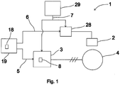
- Fig. 1 presents as a block diagram a braking apparatus 1, which comprises a machinery brake 2, and also an apparatus 3 for dynamic braking for braking an electric machine 4.
- the apparatus 3 for dynamic braking comprises a controller 8.
- the apparatus for dynamic braking also comprises controllable switches, which are connected between the stator windings of the electric machine.
- the controller 8 is fitted in connection with the control poles of the aforementioned controllable switches, for controlling the controllable switches with the switching reference formed by the controller 8.
- the controller closes the aforementioned switches connected between the stator windings of the electric machine, in which case the stator windings connect in short-circuit with each other.
- the apparatus 3 for dynamic braking and the movement management unit 19 of the electric machine are connected to each other with a serial communications bus, via which the movement management unit 19 of the electric machine and the controller 8 are connected together.
- the movement management unit 19 of the electric machine sends control parameters and also control signals 5, among others, to the controller 8 via the serial communications bus.
- the movement management unit 19 of the electric machine comprises a user panel 18, from the keyboard of which the control parameters can be entered.
- the controller 8 sends the status data of the apparatus for dynamic braking, among other things, to the movement management unit 19 of the electric machine via the serial communications bus.
- the status data can be read from the display of the user panel 18 of the movement management unit and a possible failure of the apparatus 3 for dynamic braking, among other things, can be deduced on the basis of the status data.
- the movement management unit 19 sends a starting signal 5 of the run to the controller 8, in which case the controller 8 switches its control mode and stops dynamic braking by opening the aforementioned switches connected between the stator windings of the electric machine.
- the movement management unit 19 also sends an opening signal 6 of the machinery brake to the control unit 28 of the machinery brake.
- the control unit 28 of the machinery brake controls the machinery brake 2 to open as a response to the opening signal of the machinery brake by supplying current to the magnetizing coil of the electromagnet of the machinery brake.
- the movement management unit 19 sends an end signal 5 of the run to the controller 8, in which case the controller again switches its control mode and activates dynamic braking by closing the aforementioned switches connected between the stator windings of the electric machine.
- the movement management unit 19 also sends an activation signal of the machinery brake to the control unit 28 of the machinery brake, as a response to which activation signal the control unit of the machinery brake activates the machinery brake to brake the movement of the electric machine by disconnecting the current supply to the magnetizing coil of the electromagnet of the machinery brake.
- the monitoring unit 29 of the electric drive monitors the operation of the electric drive and forms an emergency stop signal 7 when it detects a possible dangerous situation.
- Both the control unit 28 of the machinery brake and the controller 8 comprise an input for the emergency stop signal 7 formed by the monitoring unit 29 of the electric drive.
- the control unit 28 of the machinery brake activates the machinery brake 2 by disconnecting the current supply to the coil of the electromagnet of the machinery brake after it receives an emergency stop signal 7.
- the controller 8 When it receives an emergency stop signal the controller 8 switches into emergency stop mode.
- emergency stop mode the controller 8 activates the apparatus 3 for dynamic braking after a set activation delay of dynamic braking subsequent to receiving the emergency stop signal 7 such that the apparatus 3 for dynamic braking is activated after a delay with respect to the machinery brake 2.
- the controller 8 comprises an input for the speed data of the electric machine 4.
- the speed data of the electric machine 4 is determined by an encoder, which is mechanically in contact with a rotating part of the electric machine 4.
- the controller 8 also receives the speed reference of the electric machine 4, i.e. the target value of the speed of rotation of the electric machine, from the movement management unit 19.
- the movement management unit 19 sends the speed reference to the apparatus 3 for dynamic braking via the serial communications bus between the movement management unit 19 and the apparatus 3 for dynamic braking.
- the controller 8 determines the activation delay of dynamic braking on the basis of the speed data of the electric machine and the speed reference of the electric machine always using in the determination whichever of these that has the greater absolute value.
- the machinery brake 2 is activated after a certain activation delay of machinery braking.
- the activation delay is affected by, among other things, the disconnection time of the current of the coil of the electromagnet of the machinery brake 2 and also by the time it takes to engage the armature part to mechanically brake the movement of a rotating part of the electric machine 4.
- the speed of rotation of the electric machine 4 starts to decelerate such that after the activation delay of dynamic braking the speed of rotation has decelerated sufficiently in order to start dynamic braking.
- the controller 8 short-circuits the stator windings of the electric machine 4 in the manner described above.
- Fig. 4 illustrates some activation delays of machinery braking 16 and of dynamic braking 15.
- the machinery brake 2 is activated to brake the movement of the electric machine 4 after the activation delay 16 of machinery braking.
- the controller 8 activates the apparatus 3 for dynamic braking after the activation delay 15 of dynamic braking by short-circuiting the stator windings of the electric machine 4.
- the activation delay 15 of dynamic braking is longer than the activation delay 16 of machinery braking, in which case the apparatus 3 for dynamic braking is activated after a delay with respect to the machinery brake 2.
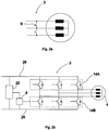
- Figs. 2a and 2b illustrate in more detail some apparatuses 3 for dynamic braking, which are also suited for use in connection with the embodiment of Fig. 1 .
- the apparatus 3 for dynamic braking of Fig. 2a comprises a contactor, the break contacts of which are connected between the stator windings of the electric machine 4.
- dynamic braking is always activated when current is not flowing in the control coil of the contactor.
- a current is supplied to the control coil of the contactor, as a result of which the contacts open and the short-circuit between the stator windings is disconnected.
- the apparatus 3 for dynamic braking of Fig. 2b is implemented with an inverter, with which variable amplitude and variable frequency current is also supplied to the electric machine 4 and thus the movement of the electric machine 4 is adjusted during normal operation of the electric machine.
- the controller 8 is fitted in connection with the control poles of the switches of the upper branch 14A of the inverter and/or of the lower branch 14B of the inverter, for switching the switches of only the lower branch 14B of the inverter, or alternatively of only the upper branch 14A of the inverter, with the switching reference of dynamic braking, which switching reference is formed by the controller 8. Dynamic braking can thus be performed, e.g.
- the apparatus for dynamic braking comprises a power source 22, the input of which is connected to the direct-current intermediate circuit 26 of the inverter.
- the output of the power source 22 is connected to the electricity supply of the controller 8, in which case the electrical energy produced during motor braking of the electric machine 4, i.e. in regenerative operation of the electric machine, 4 can be utilized as operating electricity of the controller 8.
- Fig. 3a presents an elevator system, in which an elevator car 23 and a counterweight 30 are suspended in the elevator hoistway with elevator ropes, a belt or corresponding passing via the traction sheave of the hoisting machine 4.
- the torque moving the elevator car 23 is produced in the hoisting machine 4 with a permanent-magnet synchronous motor.
- Current supply from the electricity network 27 to the permanent-magnet synchronous motor occurs during normal operation of the elevator with a frequency converter.
- the frequency converter comprises an inverter, with which the voltage of the direct-current intermediate circuit of the frequency converter is changed to a variable frequency and variable amplitude supply voltage of the permanent-magnet synchronous motor.
- the frequency converter also comprises a network inverter-rectifier, with which the electrical energy produced during motor braking of the hoisting machine 4 is returned to the electricity network 27. Because the electrical energy produced during motor braking is returned to the electricity network 27, the power supply system of the hoisting machine is implemented without a separate braking resistor.
- a braking resistor refers to the type of power resistor, with which the electrical energy produced during motor braking is converted into heat instead of returning it to the electricity network.
- the braking apparatus of the elevator system of Fig. 3a comprises a machinery brake 2 and also an apparatus 3 for dynamic braking for braking the hoisting machine 4.
- the apparatus 3 for dynamic braking is implemented using the same inverter of the frequency converter, with which inverter current is also supplied to the permanent-magnet synchronous motor of the hoisting machine 4 during normal operation of the elevator.
- the controller 8 of dynamic braking is integrated into the control unit of the frequency converter, and it is here called a control part 8 of dynamic braking.
- the control part 8 of dynamic braking is fitted in connection with the control poles of the switches of the upper branch 14A of the inverter and/or of the lower branch 14B of the inverter, for switching the switches of only the lower branch 14B of the inverter, or alternatively of only the upper branch 14A of the inverter, with the switching reference of dynamic braking, which switching reference is formed by the control part 8.
- Dynamic braking can thus be performed, e.g. in the manner described in patent application EP 2062348 A1 such that the power supply from the direct-current intermediate circuit 26 of the inverter to the hoisting machine 4 is prevented during dynamic braking.
- the controllable switches of the inverter are preferably solid-state switches.
- the control part 8 switches into the activation mode of dynamic braking and it closes the aforementioned switches of the upper branch or the lower branch of the inverter, in which case the stator windings connect in short-circuit with each other.
- the hoisting machine 4 moves, e.g. owing to the imbalance of the net load of the elevator, a source voltage is induced in the short-circuited stator windings, which source voltage causes current, which current endeavors to brake the movement of the hoisting machine 4.
- Most of the electrical energy produced in dynamic braking in this case changes to heat in the winding resistances of the hoisting machine 4, and there is no need for a separate braking resistor.
- the frequency converter comprises a power source 22, the input of which is connected to the direct-current intermediate circuit 26 of the inverter.
- the output of the power source 22 is connected to the electricity supply of the control unit of the frequency converter, in which case the electrical energy produced during motor braking of the hoisting machine 4, i.e. in regenerative operation of the hoisting machine 4, can be utilized as operating electricity of the control unit. Since the rotor magnetization of the hoisting machine 4 is implemented with the permanent magnets of the permanent-magnet synchronous motor, source voltage is induced in the stator windings always when the hoisting machine 4 starts to rotate.
- dynamic braking can be started without an external energy source immediately when the source voltage of the stator has increased sufficiently to excite the power source 22, which after being excited starts to supply operating electricity to the control part 8 of dynamic braking.
- Dynamic braking can start after the electricity supply of the control part 8 has started.
- the frequency converter and the movement management unit 19 of the elevator car are connected to each other with a serial communications bus, via which the movement management unit 19 of the elevator car and the control part 8 of dynamic braking are connected together.
- the movement management unit 19 of the elevator car sends control parameters and also control signals 5, among other things, to the control part 8 of dynamic braking via the serial communications bus.
- the movement management unit 19 of the elevator car comprises a user panel 18, from the keyboard of which the control parameters can be entered.
- the user panel 18 is disposed on the stopping floor outside the elevator hoistway.
- the control part 8 of dynamic braking for its part, sends the status data of the apparatus 3 for dynamic braking, among other things, to the movement management unit 19 of the elevator car via the serial communications bus.
- the status data can be read from the display of the user panel 18 of the movement management unit and a possible failure of the apparatus 3 for dynamic braking, among other things, can be deduced on the basis of the status data.
- the movement management unit 19 of the elevator car sends a starting signal 5 of the run to the control part 8 of dynamic braking, in which case the control part 8 switches its control mode and stops dynamic braking by opening the aforementioned switches of the upper branch of the inverter or of the lower branch of the inverter.
- the movement management unit 19 of the elevator car also sends an opening signal 6 of the machinery brake to the control unit 28 of the machinery brake.
- the control unit 28 of the machinery brake controls the machinery brake 2 to open as a response to the opening signal 6 of the machinery brake by supplying current to the magnetizing coil of the electromagnet of the machinery brake.
- the movement management unit 19 of the elevator car sends an end signal 5 of the run to the control part 8 of dynamic braking, in which case the control part 8 again switches its control mode and activates dynamic braking by closing the aforementioned switches of the upper branch of the inverter or of the lower branch of the inverter.
- the movement management unit 19 of the elevator car also sends an activation signal 6 of the machinery brake to the control unit 28 of the machinery brake, as a response to which activation signal the control unit of the machinery brake activates the machinery brake to brake the movement of the hoisting machine 4 by disconnecting the current supply to the magnetizing coil of the electromagnet of the machinery brake.
- the safety circuit 29 of the elevator monitors the operation of the elevator system and forms an emergency stop signal 7 when it detects a possible dangerous situation.
- Both the control unit 28 of the machinery brake and the control part 8 of dynamic braking comprise an input for the emergency stop signal 7 formed by the safety circuit 29 of the elevator.
- the control unit 28 of the machinery brake activates the machinery brake 2 by disconnecting the current supply to the coil of the electromagnet of the machinery brake after it receives an emergency stop signal 7.
- the control part 8 of dynamic braking When it receives an emergency stop signal the control part 8 of dynamic braking switches into emergency stop mode.
- the control part 8 of dynamic braking activates dynamic braking after a set activation delay of dynamic braking subsequent to receiving an emergency stop signal 7 such that dynamic braking is activated after a delay with respect to the machinery brake 2.
- the control part 8 of dynamic braking comprises an input for the speed data 17 of the hoisting machine 4.
- the speed data 17 of the hoisting machine 4 is determined by an encoder, which is mechanically in contact with the rotating part of the hoisting machine 4.
- the control part 8 of dynamic braking also receives the speed reference of the hoisting machine 4, i.e.
- the movement management unit 19 sends the speed reference to the control part 8 of dynamic braking via the serial communications bus between the movement control unit 19 and the frequency converter.
- the control part 8 of dynamic braking determines the activation delay of dynamic braking on the basis of the speed data of the hoisting machine and the speed reference of the hoisting machine, always using in the determination whichever of these that has the greater absolute value.
- the machinery brake 2 is activated after a certain activation delay of machinery braking.
- the activation delay of machinery braking is affected by, among other things, the disconnection time of the current of the coil of the electromagnet of the machinery brake 2 and also by the time it takes to engage the armature part to mechanically brake the movement of a rotating part of the hoisting machine 4.
- the speed of rotation of the hoisting machine 4 starts to decelerate such that after the activation delay of dynamic braking the speed of rotation has decelerated sufficiently in order to start dynamic braking.
- control part 8 of dynamic braking short-circuits the stator windings of the hoisting machine 4 in the manner described above. Because the source voltage induced in the stator windings of the hoisting machine 4 is proportional to the speed of rotation, reducing the speed of rotation also affects the short-circuit current flowing in the stator windings at the starting moment of dynamic braking such that the short-circuit current decreases as the speed of rotation decreases.
- the dynamic braking function is temporarily removed from use. Removal from use occurs by supplying a parameter that refers to prevention mode of dynamic braking to the control part 8 of dynamic braking via the user panel 18 of the movement management unit of the elevator car. In this case when it receives the parameter the control part 8 of dynamic braking switches into prevention mode of dynamic braking.
- the control part 8 of dynamic braking switches from prevention mode of dynamic braking back into normal mode of dynamic braking, e.g. when it detects the initiation of the next run of the elevator; thus prevention mode of dynamic braking is only in use during the time between runs, e.g. when the elevator car is allowed to move by opening the machinery brake manually.
- the control part 8 of dynamic braking switches from prevention mode of dynamic braking into normal mode of dynamic braking also when it receives a parameter that refers to normal mode of dynamic braking from the user panel 18 and also when it detects a communication break in the serial communications between the user panel 18 and the frequency converter. With this it can be ensured that the dynamic braking function is returned back to use always after performing machinery brake tests/safety gear tests.
- Fig. 3b illustrates e.g. the control modes of the controller 8 of the apparatus for dynamic braking according to any of the preceding embodiments.
- dynamic braking is either activated 12A or switched off 12B such that the activation and switching off of dynamic braking are selected on the basis of the control signal of the braking apparatus.
- the controller 8 switches from normal mode 12 into emergency stop mode 10, in which case dynamic braking is activated after a delay with respect to the machinery brake, e.g. such as is described in any of the preceding embodiments.
- the controller 8 switches from normal mode 12 into prevention mode 11 of dynamic braking when it receives a parameter that refers to prevention mode of dynamic braking, e.g. in the manner presented in the embodiment of Fig. 3a . If a failure is detected in the apparatus for dynamic braking, the controller switches into fault mode 13. In one embodiment of the invention, the controller 8 also sends information about the fault to the user interface 18.
Claims (12)
- Bremsapparat (1) für einen Aufzug, welcher aufweist:- einen Apparat (3) für dynamisches Bremsen, um eine elektrische Maschine (4) mittels dynamischen Bremsens zu bremsen,- einen Eingang für ein Steuersignal (5, 7) des Bremsapparates,- eine Steuerung (8) zum Steuern des Apparates (3) für ein dynamisches Bremsen als eine Antwort auf das besagte Steuersignal (5, 7) des Bremsapparates,wobei die Steuerung (8) Steuermodi (10, 11, 12, 13) zum Steuern des Apparates (3) für dynamisches Bremsen gemäß des Steuerungsmodus zur Verwendung während eines beliebigen Zeitpunktes aufweist, dadurch gekennzeichnet, dass- die Steuerung (8) angeordnet ist, den Apparat (3) für dynamisches Bremsen nachfolgend einer gesetzten Aktivierungsverzögerung (15) zum dynamischen Bremsen zu aktivieren, nachdem ein Not-Anhaltesignal (7) erhalten wurde, und- eine Maschinenbremse (2) angeordnet ist, um nachfolgend einer bestimmten Aktivierungsverzögerung (16) zum maschinellen Bremsen nach dem Erhalt des Not-Anhaltesignals (7) aktiviert zu werden,wobei die Aktivierungsverzögerung (15) zum dynamischen Bremsen länger gesetzt ist als die Aktivierungsverzögerung (16) des maschinellen Bremsens.
- Bremsapparat nach dem vorangehenden Anspruch, dadurch gekennzeichnet, dass die Steuerung (8) einen Eingang für die Geschwindigkeitsdaten (17) der elektrischen Maschine aufweist,
und dass die Aktivierungsverzögerung (15) zum dynamischen Bremsen auf der Grundlage der Geschwindigkeitsdaten (17) der elektrischen Maschine bestimmt wird. - Bremsapparat nach einem der vorangehenden Ansprüche, dadurch gekennzeichnet, dass die Steuerung (8) einen Bus zum Erhalten eines Geschwindigkeitsbezuges der elektrischen Maschine aufweist, und dass die Aktivierungsverzögerung (15) des dynamischen Bremsens auf der Grundlage der Geschwindigkeitsdaten der elektrischen Maschine oder auf der Grundlage des Geschwindigkeitsbezuges der elektrischen Maschine bestimmt wird, wobei zur Bestimmung immer derjenige dieser Werte genommen wird, der den größeren Absolut-Betrag hat.
- Bremsapparat nach einem der vorangehenden Ansprüche, dadurch gekennzeichnet, dass der Bremsapparat (1) eine Anwenderschnittstelle (18) aufweist, und dass die Steuerung (8) einen Speicher aufweist, und dass eine Datentransfierverbindung (21) zwischen der Anwender-Schnittstelle (18) und der Steuerung (8) zum Aufnehmen der Steuerparameter des dynamischen Bremsens vollzogen wird, die von der Anwender-Schnittstelle (18) in den Speicher der Steuerung (8) zu erfolgten hat.
- Bremsapparat nach einem der vorangehenden Ansprüche, dadurch gekennzeichnet, dass sich Steuerparameter des dynamischen Bremsens auf mindestens bezieht:- einen Präventiv-Modus (11) des dynamischen Bremsens- ein Normal-Modus (12) des dynamischen Bremsens- eine Nominalgeschwindigkeit der elektrischen Maschine- ein durchschnittliches Abbremsen der elektrischen Maschine mit maschinellem Bremsen- Zustandsdaten des Apparats zum dynamischen Bremsen.
- Elektrischer Antrieb für einen Aufzug, der eine elektrische Maschine (4) aufweist, dadurch gekennzeichnet, dass der elektrische Antrieb einen Bremsapparat (1) gemäß einem der Ansprüche 1 - 5 zum Bremsen der elektrischen Maschine (4) aufweist.
- Elektrischer Antrieb gemäß Anspruch 6, dadurch gekennzeichnet, dass die besagte elektrische Maschine (4) einen Permanentmagneten-Synchronmotor aufweist.
- Elektrischer Antrieb gemäß einem der Ansprüche 6 oder 7, dadurch gekennzeichnet, dass der elektrische Antrieb einen Frequenz-Umwandler (20) aufweist, der an die elektrische Maschine (4) zum Antreiben der elektrischen Maschine (4) angeschlossen ist, und dass der Frequenzwandler (20) einen Inverter (14A, 14B) aufweist, um einen Strom mit variabler Amplitude und variabler Frequenz an die elektrische Maschine (4) zu führen.
- Aufzugssystem, dadurch gekennzeichnet, dass das Aufzugssystem einen elektrischen Antrieb gemäß einem der Ansprüche 6-8 zum Bewegen einer Aufzugskabine (23) in einem Aufzugsschacht aufweist.
- Aufzugssystem nach Anspruch 9, dadurch gekennzeichnet, dass der elektrische Antrieb (4) als Hebemaschine des Aufzuges und der Frequenz-Umwandler (20) in dem Aufzugsschacht eingepasst sind.
- Aufzugssystem nach Anspruch 9 oder 10, dadurch gekennzeichnet, das die besagte Anwender-Schnittstelle (18) außerhalb des Aufzugsschachtes vorliegt.
- Aufzugssystem nach einem der Ansprüche 9 - 11, dadurch gekennzeichnet, dass die Steuerung (8) angeordnet ist, um in einen Präventiv-Modus (11) des dynamischen Bremens geschaltet zu werden, wenn die Steuerung (8) einen Parameter empfängt, der sich auf einen Präventions-Modus des dynamischen Bremsens von der Anwender-Schnittstelle (18) bezieht, und dass die Steuerung angeordnet ist, von dem Präventiv-Modus des dynamischen Bremsens in einen Normal-Modus (12) des dynamischen Bremsens geschaltet zu werden, nachdem sie mindestens feststellt:- die Steuerung (8) detektiert einen Start eines nächsten Laufes des Aufzuges- die Steuerung (8) empfängt einen Parameter von der Anwender-Schnittstelle, der sich auf den Normal-Modus (12) zum dynamischen Bremsen (18) bezieht- die Steuerung (8) detektiert eine Kommunikations-Unterbrechung in einer Datenübertragungsverbindung (21) zwischen der Anwenderschnittstelle und der Steuerung.
Priority Applications (2)
| Application Number | Priority Date | Filing Date | Title |
|---|---|---|---|
| EP17188256.6A EP3287404B1 (de) | 2009-11-02 | 2010-11-01 | Aufzugsystem mit bremsvorrichtung und elektrischem antrieb |
| DK17188256.6T DK3287404T3 (da) | 2009-11-02 | 2010-11-01 | Elevatorsystem omfattende bremseapparat og elektrisk drev |
Applications Claiming Priority (2)
| Application Number | Priority Date | Filing Date | Title |
|---|---|---|---|
| FI20096131A FI121882B (fi) | 2009-11-02 | 2009-11-02 | Jarrutuslaitteisto, sähkökäyttö sekä hissijärjestelmä |
| PCT/FI2010/050867 WO2011051571A1 (en) | 2009-11-02 | 2010-11-01 | Braking apparatus, electric drive, and elevator system |
Related Child Applications (1)
| Application Number | Title | Priority Date | Filing Date |
|---|---|---|---|
| EP17188256.6A Division EP3287404B1 (de) | 2009-11-02 | 2010-11-01 | Aufzugsystem mit bremsvorrichtung und elektrischem antrieb |
Publications (3)
| Publication Number | Publication Date |
|---|---|
| EP2496507A1 EP2496507A1 (de) | 2012-09-12 |
| EP2496507A4 EP2496507A4 (de) | 2016-01-13 |
| EP2496507B1 true EP2496507B1 (de) | 2017-09-06 |
Family
ID=41395185
Family Applications (2)
| Application Number | Title | Priority Date | Filing Date |
|---|---|---|---|
| EP17188256.6A Active EP3287404B1 (de) | 2009-11-02 | 2010-11-01 | Aufzugsystem mit bremsvorrichtung und elektrischem antrieb |
| EP10826181.9A Active EP2496507B1 (de) | 2009-11-02 | 2010-11-01 | Bremsvorrichtung und elektrischer antrieb für ein aufzugsystem und aufzugsystem, das sie aufweist |
Family Applications Before (1)
| Application Number | Title | Priority Date | Filing Date |
|---|---|---|---|
| EP17188256.6A Active EP3287404B1 (de) | 2009-11-02 | 2010-11-01 | Aufzugsystem mit bremsvorrichtung und elektrischem antrieb |
Country Status (8)
| Country | Link |
|---|---|
| US (1) | US8890448B2 (de) |
| EP (2) | EP3287404B1 (de) |
| CN (1) | CN102712442B (de) |
| DK (2) | DK3287404T3 (de) |
| ES (1) | ES2640460T3 (de) |
| FI (1) | FI121882B (de) |
| HK (1) | HK1176595A1 (de) |
| WO (1) | WO2011051571A1 (de) |
Families Citing this family (24)
| Publication number | Priority date | Publication date | Assignee | Title |
|---|---|---|---|---|
| FI122125B (fi) * | 2010-04-07 | 2011-08-31 | Kone Corp | Säätölaite ja hissin sähkökäyttö |
| JP5680190B2 (ja) * | 2010-05-21 | 2015-03-04 | オーチス エレベータ カンパニーOtis Elevator Company | ブレーキ装置 |
| JP5808923B2 (ja) * | 2011-03-18 | 2015-11-10 | Ntn株式会社 | モータ駆動装置及び電気自動車 |
| FI123506B (fi) | 2012-05-31 | 2013-06-14 | Kone Corp | Hissin käyttölaite sekä hissin turvajärjestely |
| EP2888190B1 (de) * | 2012-08-22 | 2019-01-02 | Otis Elevator Company | Aufzugssystem mit dynamischer bremsung |
| WO2014113006A1 (en) | 2013-01-17 | 2014-07-24 | Otis Elevator Company | Enhanced deceleration propulsion system for elevators |
| GB2526072B (en) * | 2014-05-02 | 2019-08-14 | Ensota Ltd | A method of operating an automatic door installation |
| CN104495550B (zh) * | 2014-12-31 | 2017-11-14 | 上海新时达电气股份有限公司 | 封星保护方法及装置 |
| FI125887B (en) * | 2015-01-16 | 2016-03-31 | Kone Corp | Elevator rescue device |
| EP3072842B1 (de) * | 2015-03-23 | 2019-09-25 | Kone Corporation | Rettungssystem für einen aufzug |
| JP6200461B2 (ja) * | 2015-07-14 | 2017-09-20 | ファナック株式会社 | ダイナミックブレーキ回路を有するモータ駆動装置 |
| JP6200467B2 (ja) * | 2015-08-07 | 2017-09-20 | ファナック株式会社 | ブレーキの異常を検出する機能を備えたモータ制御システム |
| EP3153441B1 (de) * | 2015-10-08 | 2018-02-07 | KONE Corporation | Verfahren zur steuerung eines aufzugs |
| JP6532965B2 (ja) * | 2016-02-15 | 2019-06-19 | 株式会社日立製作所 | エレベータ及びその制御装置 |
| US11375958B2 (en) | 2016-06-13 | 2022-07-05 | Happy Health Inc. | Wearable athletic monitoring using digital modulation |
| CN106927330B (zh) * | 2017-03-14 | 2019-06-04 | 日立电梯(中国)有限公司 | 电梯制动控制方法及系统 |
| US10680538B2 (en) | 2017-09-28 | 2020-06-09 | Otis Elevator Company | Emergency braking for a drive system |
| US11040848B2 (en) | 2018-03-27 | 2021-06-22 | Otis Elevator Company | Elevator machine brake delay control |
| EP3560874B1 (de) | 2018-04-26 | 2021-12-01 | KONE Corporation | Verfahren und vorrcihtung für die zustandsüberwachung einer induktiven bremsvorrichtung einer aufzugskabine |
| EP3599200B1 (de) * | 2018-07-23 | 2022-06-01 | KONE Corporation | Aufzug |
| EP3611837A1 (de) * | 2018-08-17 | 2020-02-19 | Goodrich Actuation Systems Limited | Elektromotor |
| US11866295B2 (en) | 2018-08-20 | 2024-01-09 | Otis Elevator Company | Active braking for immediate stops |
| CN111252637A (zh) * | 2018-12-03 | 2020-06-09 | 株式会社日立制作所 | 电梯控制系统及电梯控制方法 |
| CN110002308B (zh) * | 2019-04-02 | 2023-05-12 | 冯光辉 | 实时监测电梯制动器制动能力的方法 |
Citations (1)
| Publication number | Priority date | Publication date | Assignee | Title |
|---|---|---|---|---|
| GB451133A (en) * | 1935-04-30 | 1936-07-30 | Gen Electric Co Ltd | Improvements in or relating to emergency braking means for electric winders |
Family Cites Families (27)
| Publication number | Priority date | Publication date | Assignee | Title |
|---|---|---|---|---|
| US3458790A (en) * | 1966-08-31 | 1969-07-29 | Web Press Eng Inc | Regenerative direct current motor control having field and armature control |
| US3488570A (en) * | 1967-12-29 | 1970-01-06 | Unit Rig & Equip | Combined dynamic and friction braking |
| CH508307A (de) * | 1969-11-07 | 1971-05-31 | Bbc Brown Boveri & Cie | Durch einen Drehstrommotor angetriebenes Hebezeug mit einer Einrichtung zum Abbremsen |
| US3657625A (en) * | 1969-11-24 | 1972-04-18 | Westinghouse Electric Corp | System for blending dynamic and regenerative braking |
| GB1315589A (en) * | 1970-01-21 | 1973-05-02 | Hitachi Ltd | Control apparatus for an elevator car |
| US3804043A (en) * | 1971-01-20 | 1974-04-16 | Cutters Machine Co Inc | Needle positioner for a sewing machine |
| US3774095A (en) * | 1972-09-20 | 1973-11-20 | Westinghouse Air Brake Co | System for blending regenerative and dynamic and friction braking |
| NL7407016A (de) * | 1973-06-07 | 1974-12-10 | ||
| JPS5314283B2 (de) * | 1973-08-20 | 1978-05-16 | ||
| US4074176B1 (en) | 1976-06-07 | 1986-05-20 | Marine Electric Corp | Motor protector |
| US4225813A (en) * | 1978-11-28 | 1980-09-30 | Westinghouse Electric Corp. | Transit vehicle dynamic brake control apparatus |
| JPH0697875B2 (ja) * | 1987-05-20 | 1994-11-30 | 日本オ−チス・エレベ−タ株式会社 | エレベ−タ駆動用インバ−タ |
| JP2754835B2 (ja) * | 1990-02-22 | 1998-05-20 | 三菱電機株式会社 | インバータの運転指令方法 |
| DE69229961T2 (de) * | 1991-04-09 | 1999-12-23 | Honda Motor Co Ltd | Bremsregelsystem für ein elektrisches Fahrzeug |
| US5361022A (en) * | 1993-03-23 | 1994-11-01 | E. F. Bavis & Associates, Inc. | Method and apparatus for electrical dynamic braking |
| KR100206106B1 (ko) * | 1993-12-22 | 1999-07-01 | 캐빈 엠. 리어든 | 전기차량의 속도제어장치 및 그 제어방법 |
| JP3309648B2 (ja) * | 1995-06-22 | 2002-07-29 | 三菱電機株式会社 | エレベータの制御装置 |
| US6441573B1 (en) * | 2000-04-28 | 2002-08-27 | Daimlercrysler Ag | Blended electrical/friction braking system with electric brake feedback monitor and method of use thereof |
| EP1520829B1 (de) * | 2002-07-10 | 2020-04-01 | Mitsubishi Denki Kabushiki Kaisha | Steuerung für aufzug |
| JP5420140B2 (ja) * | 2006-02-27 | 2014-02-19 | 東芝エレベータ株式会社 | エレベータ制御装置 |
| FI118406B (fi) * | 2006-09-11 | 2007-10-31 | Kone Corp | Menetelmä ja laitteisto moottorin jarruttamiseksi |
| US8186483B2 (en) * | 2006-11-08 | 2012-05-29 | Otis Elevator Company | Elevator braking device |
| FI20070486A (fi) * | 2007-01-03 | 2008-07-04 | Kone Corp | Hissin turvajärjestely |
| WO2008155164A1 (de) * | 2007-06-18 | 2008-12-24 | Inventio Ag | Einrichtung und verfahren zum überwachen einer bremseinrichtung |
| FI121493B (fi) * | 2007-07-26 | 2010-11-30 | Kone Corp | Sähkömoottorikäyttö |
| US8154228B2 (en) * | 2009-06-10 | 2012-04-10 | Kollmorgen Corporation | Dynamic braking for electric motors |
| FI121663B (fi) * | 2009-10-09 | 2011-02-28 | Kone Corp | Mittausjärjestely, valvontajärjestely sekä hissijärjestelmä |
-
2009
- 2009-11-02 FI FI20096131A patent/FI121882B/fi active IP Right Grant
-
2010
- 2010-11-01 DK DK17188256.6T patent/DK3287404T3/da active
- 2010-11-01 WO PCT/FI2010/050867 patent/WO2011051571A1/en active Application Filing
- 2010-11-01 DK DK10826181.9T patent/DK2496507T3/en active
- 2010-11-01 ES ES10826181.9T patent/ES2640460T3/es active Active
- 2010-11-01 CN CN201080060287.7A patent/CN102712442B/zh active Active
- 2010-11-01 EP EP17188256.6A patent/EP3287404B1/de active Active
- 2010-11-01 EP EP10826181.9A patent/EP2496507B1/de active Active
-
2012
- 2012-05-02 US US13/462,341 patent/US8890448B2/en active Active
-
2013
- 2013-03-28 HK HK13103900.8A patent/HK1176595A1/xx unknown
Patent Citations (1)
| Publication number | Priority date | Publication date | Assignee | Title |
|---|---|---|---|---|
| GB451133A (en) * | 1935-04-30 | 1936-07-30 | Gen Electric Co Ltd | Improvements in or relating to emergency braking means for electric winders |
Also Published As
| Publication number | Publication date |
|---|---|
| EP3287404B1 (de) | 2019-05-15 |
| HK1176595A1 (en) | 2013-08-02 |
| FI121882B (fi) | 2011-05-31 |
| US20120217098A1 (en) | 2012-08-30 |
| EP2496507A1 (de) | 2012-09-12 |
| CN102712442A (zh) | 2012-10-03 |
| WO2011051571A1 (en) | 2011-05-05 |
| US8890448B2 (en) | 2014-11-18 |
| EP3287404A1 (de) | 2018-02-28 |
| EP2496507A4 (de) | 2016-01-13 |
| FI20096131A0 (fi) | 2009-11-02 |
| ES2640460T3 (es) | 2017-11-03 |
| CN102712442B (zh) | 2014-09-10 |
| DK3287404T3 (da) | 2019-08-19 |
| DK2496507T3 (en) | 2017-10-02 |
Similar Documents
| Publication | Publication Date | Title |
|---|---|---|
| EP2496507B1 (de) | Bremsvorrichtung und elektrischer antrieb für ein aufzugsystem und aufzugsystem, das sie aufweist | |
| EP2062348B1 (de) | Verfahren und vorrichtung zum bremsen eines motors | |
| EP2855324B1 (de) | Sicherheitsanordnung für einen aufzug | |
| CN101816122B (zh) | 对电驱动器的输出的限制和对电梯的保护 | |
| CN108946369B (zh) | 主电源关闭后在电梯中执行手动驱动的方法 | |
| JP2008056428A (ja) | エレベータ制御装置 | |
| CN102471020B (zh) | 电梯的控制装置 | |
| KR101219230B1 (ko) | 엘리베이터의 안전 회로 장치 | |
| CN102378731B (zh) | 电梯装置 | |
| JPH04286587A (ja) | リニアモータ式エレベータ制御装置 | |
| US20240132325A1 (en) | Method, elevator, and electric power converter | |
| JP2004159423A (ja) | 電動機の制御装置 |
Legal Events
| Date | Code | Title | Description |
|---|---|---|---|
| PUAI | Public reference made under article 153(3) epc to a published international application that has entered the european phase |
Free format text: ORIGINAL CODE: 0009012 |
|
| 17P | Request for examination filed |
Effective date: 20120426 |
|
| AK | Designated contracting states |
Kind code of ref document: A1 Designated state(s): AL AT BE BG CH CY CZ DE DK EE ES FI FR GB GR HR HU IE IS IT LI LT LU LV MC MK MT NL NO PL PT RO RS SE SI SK SM TR |
|
| DAX | Request for extension of the european patent (deleted) | ||
| RA4 | Supplementary search report drawn up and despatched (corrected) |
Effective date: 20151214 |
|
| RIC1 | Information provided on ipc code assigned before grant |
Ipc: B66B 5/02 20060101ALI20151208BHEP Ipc: B66B 1/32 20060101ALI20151208BHEP Ipc: B66B 1/30 20060101AFI20151208BHEP |
|
| REG | Reference to a national code |
Ref country code: DE Ref legal event code: R079 Ref document number: 602010045121 Country of ref document: DE Free format text: PREVIOUS MAIN CLASS: B66B0001300000 Ipc: B66B0001320000 |
|
| GRAP | Despatch of communication of intention to grant a patent |
Free format text: ORIGINAL CODE: EPIDOSNIGR1 |
|
| RIC1 | Information provided on ipc code assigned before grant |
Ipc: B66B 1/30 20060101ALI20170329BHEP Ipc: B66B 1/32 20060101AFI20170329BHEP Ipc: B66B 5/02 20060101ALI20170329BHEP Ipc: B60L 7/24 20060101ALI20170329BHEP |
|
| INTG | Intention to grant announced |
Effective date: 20170421 |
|
| GRAS | Grant fee paid |
Free format text: ORIGINAL CODE: EPIDOSNIGR3 |
|
| GRAA | (expected) grant |
Free format text: ORIGINAL CODE: 0009210 |
|
| AK | Designated contracting states |
Kind code of ref document: B1 Designated state(s): AL AT BE BG CH CY CZ DE DK EE ES FI FR GB GR HR HU IE IS IT LI LT LU LV MC MK MT NL NO PL PT RO RS SE SI SK SM TR |
|
| REG | Reference to a national code |
Ref country code: GB Ref legal event code: FG4D |
|
| REG | Reference to a national code |
Ref country code: CH Ref legal event code: EP Ref country code: AT Ref legal event code: REF Ref document number: 925650 Country of ref document: AT Kind code of ref document: T Effective date: 20170915 |
|
| REG | Reference to a national code |
Ref country code: DK Ref legal event code: T3 Effective date: 20170928 |
|
| REG | Reference to a national code |
Ref country code: IE Ref legal event code: FG4D |
|
| REG | Reference to a national code |
Ref country code: DE Ref legal event code: R096 Ref document number: 602010045121 Country of ref document: DE |
|
| REG | Reference to a national code |
Ref country code: ES Ref legal event code: FG2A Ref document number: 2640460 Country of ref document: ES Kind code of ref document: T3 Effective date: 20171103 |
|
| REG | Reference to a national code |
Ref country code: FR Ref legal event code: PLFP Year of fee payment: 8 |
|
| REG | Reference to a national code |
Ref country code: NL Ref legal event code: MP Effective date: 20170906 |
|
| REG | Reference to a national code |
Ref country code: LT Ref legal event code: MG4D |
|
| PG25 | Lapsed in a contracting state [announced via postgrant information from national office to epo] |
Ref country code: LT Free format text: LAPSE BECAUSE OF FAILURE TO SUBMIT A TRANSLATION OF THE DESCRIPTION OR TO PAY THE FEE WITHIN THE PRESCRIBED TIME-LIMIT Effective date: 20170906 Ref country code: FI Free format text: LAPSE BECAUSE OF FAILURE TO SUBMIT A TRANSLATION OF THE DESCRIPTION OR TO PAY THE FEE WITHIN THE PRESCRIBED TIME-LIMIT Effective date: 20170906 Ref country code: SE Free format text: LAPSE BECAUSE OF FAILURE TO SUBMIT A TRANSLATION OF THE DESCRIPTION OR TO PAY THE FEE WITHIN THE PRESCRIBED TIME-LIMIT Effective date: 20170906 Ref country code: NO Free format text: LAPSE BECAUSE OF FAILURE TO SUBMIT A TRANSLATION OF THE DESCRIPTION OR TO PAY THE FEE WITHIN THE PRESCRIBED TIME-LIMIT Effective date: 20171206 Ref country code: HR Free format text: LAPSE BECAUSE OF FAILURE TO SUBMIT A TRANSLATION OF THE DESCRIPTION OR TO PAY THE FEE WITHIN THE PRESCRIBED TIME-LIMIT Effective date: 20170906 |
|
| REG | Reference to a national code |
Ref country code: AT Ref legal event code: MK05 Ref document number: 925650 Country of ref document: AT Kind code of ref document: T Effective date: 20170906 |
|
| PG25 | Lapsed in a contracting state [announced via postgrant information from national office to epo] |
Ref country code: BG Free format text: LAPSE BECAUSE OF FAILURE TO SUBMIT A TRANSLATION OF THE DESCRIPTION OR TO PAY THE FEE WITHIN THE PRESCRIBED TIME-LIMIT Effective date: 20171206 Ref country code: RS Free format text: LAPSE BECAUSE OF FAILURE TO SUBMIT A TRANSLATION OF THE DESCRIPTION OR TO PAY THE FEE WITHIN THE PRESCRIBED TIME-LIMIT Effective date: 20170906 Ref country code: LV Free format text: LAPSE BECAUSE OF FAILURE TO SUBMIT A TRANSLATION OF THE DESCRIPTION OR TO PAY THE FEE WITHIN THE PRESCRIBED TIME-LIMIT Effective date: 20170906 Ref country code: GR Free format text: LAPSE BECAUSE OF FAILURE TO SUBMIT A TRANSLATION OF THE DESCRIPTION OR TO PAY THE FEE WITHIN THE PRESCRIBED TIME-LIMIT Effective date: 20171207 |
|
| PG25 | Lapsed in a contracting state [announced via postgrant information from national office to epo] |
Ref country code: NL Free format text: LAPSE BECAUSE OF FAILURE TO SUBMIT A TRANSLATION OF THE DESCRIPTION OR TO PAY THE FEE WITHIN THE PRESCRIBED TIME-LIMIT Effective date: 20170906 |
|
| PG25 | Lapsed in a contracting state [announced via postgrant information from national office to epo] |
Ref country code: PL Free format text: LAPSE BECAUSE OF FAILURE TO SUBMIT A TRANSLATION OF THE DESCRIPTION OR TO PAY THE FEE WITHIN THE PRESCRIBED TIME-LIMIT Effective date: 20170906 Ref country code: CZ Free format text: LAPSE BECAUSE OF FAILURE TO SUBMIT A TRANSLATION OF THE DESCRIPTION OR TO PAY THE FEE WITHIN THE PRESCRIBED TIME-LIMIT Effective date: 20170906 Ref country code: RO Free format text: LAPSE BECAUSE OF FAILURE TO SUBMIT A TRANSLATION OF THE DESCRIPTION OR TO PAY THE FEE WITHIN THE PRESCRIBED TIME-LIMIT Effective date: 20170906 |
|
| PG25 | Lapsed in a contracting state [announced via postgrant information from national office to epo] |
Ref country code: SM Free format text: LAPSE BECAUSE OF FAILURE TO SUBMIT A TRANSLATION OF THE DESCRIPTION OR TO PAY THE FEE WITHIN THE PRESCRIBED TIME-LIMIT Effective date: 20170906 Ref country code: SK Free format text: LAPSE BECAUSE OF FAILURE TO SUBMIT A TRANSLATION OF THE DESCRIPTION OR TO PAY THE FEE WITHIN THE PRESCRIBED TIME-LIMIT Effective date: 20170906 Ref country code: IS Free format text: LAPSE BECAUSE OF FAILURE TO SUBMIT A TRANSLATION OF THE DESCRIPTION OR TO PAY THE FEE WITHIN THE PRESCRIBED TIME-LIMIT Effective date: 20180106 Ref country code: AT Free format text: LAPSE BECAUSE OF FAILURE TO SUBMIT A TRANSLATION OF THE DESCRIPTION OR TO PAY THE FEE WITHIN THE PRESCRIBED TIME-LIMIT Effective date: 20170906 Ref country code: EE Free format text: LAPSE BECAUSE OF FAILURE TO SUBMIT A TRANSLATION OF THE DESCRIPTION OR TO PAY THE FEE WITHIN THE PRESCRIBED TIME-LIMIT Effective date: 20170906 Ref country code: IT Free format text: LAPSE BECAUSE OF FAILURE TO SUBMIT A TRANSLATION OF THE DESCRIPTION OR TO PAY THE FEE WITHIN THE PRESCRIBED TIME-LIMIT Effective date: 20170906 |
|
| REG | Reference to a national code |
Ref country code: DE Ref legal event code: R097 Ref document number: 602010045121 Country of ref document: DE |
|
| PG25 | Lapsed in a contracting state [announced via postgrant information from national office to epo] |
Ref country code: MC Free format text: LAPSE BECAUSE OF FAILURE TO SUBMIT A TRANSLATION OF THE DESCRIPTION OR TO PAY THE FEE WITHIN THE PRESCRIBED TIME-LIMIT Effective date: 20170906 |
|
| PLBE | No opposition filed within time limit |
Free format text: ORIGINAL CODE: 0009261 |
|
| STAA | Information on the status of an ep patent application or granted ep patent |
Free format text: STATUS: NO OPPOSITION FILED WITHIN TIME LIMIT |
|
| PG25 | Lapsed in a contracting state [announced via postgrant information from national office to epo] |
Ref country code: LI Free format text: LAPSE BECAUSE OF NON-PAYMENT OF DUE FEES Effective date: 20171130 Ref country code: CH Free format text: LAPSE BECAUSE OF NON-PAYMENT OF DUE FEES Effective date: 20171130 |
|
| 26N | No opposition filed |
Effective date: 20180607 |
|
| PG25 | Lapsed in a contracting state [announced via postgrant information from national office to epo] |
Ref country code: SI Free format text: LAPSE BECAUSE OF FAILURE TO SUBMIT A TRANSLATION OF THE DESCRIPTION OR TO PAY THE FEE WITHIN THE PRESCRIBED TIME-LIMIT Effective date: 20170906 Ref country code: LU Free format text: LAPSE BECAUSE OF NON-PAYMENT OF DUE FEES Effective date: 20171101 |
|
| REG | Reference to a national code |
Ref country code: BE Ref legal event code: MM Effective date: 20171130 |
|
| REG | Reference to a national code |
Ref country code: IE Ref legal event code: MM4A |
|
| PG25 | Lapsed in a contracting state [announced via postgrant information from national office to epo] |
Ref country code: MT Free format text: LAPSE BECAUSE OF NON-PAYMENT OF DUE FEES Effective date: 20171101 |
|
| PG25 | Lapsed in a contracting state [announced via postgrant information from national office to epo] |
Ref country code: IE Free format text: LAPSE BECAUSE OF NON-PAYMENT OF DUE FEES Effective date: 20171101 |
|
| PG25 | Lapsed in a contracting state [announced via postgrant information from national office to epo] |
Ref country code: BE Free format text: LAPSE BECAUSE OF NON-PAYMENT OF DUE FEES Effective date: 20171130 |
|
| PG25 | Lapsed in a contracting state [announced via postgrant information from national office to epo] |
Ref country code: HU Free format text: LAPSE BECAUSE OF FAILURE TO SUBMIT A TRANSLATION OF THE DESCRIPTION OR TO PAY THE FEE WITHIN THE PRESCRIBED TIME-LIMIT; INVALID AB INITIO Effective date: 20101101 |
|
| PG25 | Lapsed in a contracting state [announced via postgrant information from national office to epo] |
Ref country code: CY Free format text: LAPSE BECAUSE OF NON-PAYMENT OF DUE FEES Effective date: 20170906 |
|
| PG25 | Lapsed in a contracting state [announced via postgrant information from national office to epo] |
Ref country code: MK Free format text: LAPSE BECAUSE OF FAILURE TO SUBMIT A TRANSLATION OF THE DESCRIPTION OR TO PAY THE FEE WITHIN THE PRESCRIBED TIME-LIMIT Effective date: 20170906 |
|
| PG25 | Lapsed in a contracting state [announced via postgrant information from national office to epo] |
Ref country code: TR Free format text: LAPSE BECAUSE OF FAILURE TO SUBMIT A TRANSLATION OF THE DESCRIPTION OR TO PAY THE FEE WITHIN THE PRESCRIBED TIME-LIMIT Effective date: 20170906 |
|
| PG25 | Lapsed in a contracting state [announced via postgrant information from national office to epo] |
Ref country code: PT Free format text: LAPSE BECAUSE OF FAILURE TO SUBMIT A TRANSLATION OF THE DESCRIPTION OR TO PAY THE FEE WITHIN THE PRESCRIBED TIME-LIMIT Effective date: 20170906 |
|
| PG25 | Lapsed in a contracting state [announced via postgrant information from national office to epo] |
Ref country code: AL Free format text: LAPSE BECAUSE OF FAILURE TO SUBMIT A TRANSLATION OF THE DESCRIPTION OR TO PAY THE FEE WITHIN THE PRESCRIBED TIME-LIMIT Effective date: 20170906 |
|
| PGFP | Annual fee paid to national office [announced via postgrant information from national office to epo] |
Ref country code: ES Payment date: 20230125 Year of fee payment: 13 |
|
| P01 | Opt-out of the competence of the unified patent court (upc) registered |
Effective date: 20230525 |
|
| PGFP | Annual fee paid to national office [announced via postgrant information from national office to epo] |
Ref country code: GB Payment date: 20231123 Year of fee payment: 14 |
|
| PGFP | Annual fee paid to national office [announced via postgrant information from national office to epo] |
Ref country code: FR Payment date: 20231120 Year of fee payment: 14 Ref country code: DK Payment date: 20231124 Year of fee payment: 14 Ref country code: DE Payment date: 20231121 Year of fee payment: 14 |