EP4354017A1 - Système de fixation pour une lampe, élément de fixation et lampe - Google Patents
Système de fixation pour une lampe, élément de fixation et lampe Download PDFInfo
- Publication number
- EP4354017A1 EP4354017A1 EP23202979.3A EP23202979A EP4354017A1 EP 4354017 A1 EP4354017 A1 EP 4354017A1 EP 23202979 A EP23202979 A EP 23202979A EP 4354017 A1 EP4354017 A1 EP 4354017A1
- Authority
- EP
- European Patent Office
- Prior art keywords
- hook
- hooking
- movable
- hooking means
- locking
- Prior art date
- Legal status (The legal status is an assumption and is not a legal conclusion. Google has not performed a legal analysis and makes no representation as to the accuracy of the status listed.)
- Pending
Links
- 230000000295 complement effect Effects 0.000 claims abstract description 5
- 239000002184 metal Substances 0.000 claims description 8
- 230000001427 coherent effect Effects 0.000 claims description 3
- 230000015572 biosynthetic process Effects 0.000 claims 1
- 239000011324 bead Substances 0.000 description 6
- 230000000694 effects Effects 0.000 description 6
- 230000005484 gravity Effects 0.000 description 5
- 210000000078 claw Anatomy 0.000 description 4
- 230000005489 elastic deformation Effects 0.000 description 3
- 238000009434 installation Methods 0.000 description 2
- 239000000463 material Substances 0.000 description 2
- 230000007246 mechanism Effects 0.000 description 2
- 230000003287 optical effect Effects 0.000 description 2
- 206010041953 Staring Diseases 0.000 description 1
- 230000009471 action Effects 0.000 description 1
- 238000004873 anchoring Methods 0.000 description 1
- 230000008901 benefit Effects 0.000 description 1
- 230000001066 destructive effect Effects 0.000 description 1
- 230000003993 interaction Effects 0.000 description 1
- 238000012423 maintenance Methods 0.000 description 1
- 238000000034 method Methods 0.000 description 1
- 230000036316 preload Effects 0.000 description 1
- 230000008569 process Effects 0.000 description 1
- 230000005855 radiation Effects 0.000 description 1
- 230000002441 reversible effect Effects 0.000 description 1
Images

Classifications
-
- F—MECHANICAL ENGINEERING; LIGHTING; HEATING; WEAPONS; BLASTING
- F21—LIGHTING
- F21V—FUNCTIONAL FEATURES OR DETAILS OF LIGHTING DEVICES OR SYSTEMS THEREOF; STRUCTURAL COMBINATIONS OF LIGHTING DEVICES WITH OTHER ARTICLES, NOT OTHERWISE PROVIDED FOR
- F21V21/00—Supporting, suspending, or attaching arrangements for lighting devices; Hand grips
- F21V21/08—Devices for easy attachment to any desired place, e.g. clip, clamp, magnet
- F21V21/088—Clips; Clamps
-
- F—MECHANICAL ENGINEERING; LIGHTING; HEATING; WEAPONS; BLASTING
- F21—LIGHTING
- F21S—NON-PORTABLE LIGHTING DEVICES; SYSTEMS THEREOF; VEHICLE LIGHTING DEVICES SPECIALLY ADAPTED FOR VEHICLE EXTERIORS
- F21S8/00—Lighting devices intended for fixed installation
-
- F—MECHANICAL ENGINEERING; LIGHTING; HEATING; WEAPONS; BLASTING
- F21—LIGHTING
- F21V—FUNCTIONAL FEATURES OR DETAILS OF LIGHTING DEVICES OR SYSTEMS THEREOF; STRUCTURAL COMBINATIONS OF LIGHTING DEVICES WITH OTHER ARTICLES, NOT OTHERWISE PROVIDED FOR
- F21V17/00—Fastening of component parts of lighting devices, e.g. shades, globes, refractors, reflectors, filters, screens, grids or protective cages
- F21V17/10—Fastening of component parts of lighting devices, e.g. shades, globes, refractors, reflectors, filters, screens, grids or protective cages characterised by specific fastening means or way of fastening
- F21V17/16—Fastening of component parts of lighting devices, e.g. shades, globes, refractors, reflectors, filters, screens, grids or protective cages characterised by specific fastening means or way of fastening by deformation of parts; Snap action mounting
- F21V17/164—Fastening of component parts of lighting devices, e.g. shades, globes, refractors, reflectors, filters, screens, grids or protective cages characterised by specific fastening means or way of fastening by deformation of parts; Snap action mounting the parts being subjected to bending, e.g. snap joints
-
- F—MECHANICAL ENGINEERING; LIGHTING; HEATING; WEAPONS; BLASTING
- F21—LIGHTING
- F21V—FUNCTIONAL FEATURES OR DETAILS OF LIGHTING DEVICES OR SYSTEMS THEREOF; STRUCTURAL COMBINATIONS OF LIGHTING DEVICES WITH OTHER ARTICLES, NOT OTHERWISE PROVIDED FOR
- F21V19/00—Fastening of light sources or lamp holders
- F21V19/04—Fastening of light sources or lamp holders with provision for changing light source, e.g. turret
-
- F—MECHANICAL ENGINEERING; LIGHTING; HEATING; WEAPONS; BLASTING
- F21—LIGHTING
- F21V—FUNCTIONAL FEATURES OR DETAILS OF LIGHTING DEVICES OR SYSTEMS THEREOF; STRUCTURAL COMBINATIONS OF LIGHTING DEVICES WITH OTHER ARTICLES, NOT OTHERWISE PROVIDED FOR
- F21V21/00—Supporting, suspending, or attaching arrangements for lighting devices; Hand grips
- F21V21/02—Wall, ceiling, or floor bases; Fixing pendants or arms to the bases
- F21V21/025—Elongated bases having a U-shaped cross section
-
- F—MECHANICAL ENGINEERING; LIGHTING; HEATING; WEAPONS; BLASTING
- F21—LIGHTING
- F21V—FUNCTIONAL FEATURES OR DETAILS OF LIGHTING DEVICES OR SYSTEMS THEREOF; STRUCTURAL COMBINATIONS OF LIGHTING DEVICES WITH OTHER ARTICLES, NOT OTHERWISE PROVIDED FOR
- F21V21/00—Supporting, suspending, or attaching arrangements for lighting devices; Hand grips
- F21V21/02—Wall, ceiling, or floor bases; Fixing pendants or arms to the bases
- F21V21/04—Recessed bases
Definitions
- the invention relates to a fastening system for a lamp for tool-free mounting of a lamp element on a support unit by means of two complementary hooking means, comprising at least one element hook which is assigned to the lamp element, and at least one support hook which is assigned to the support unit, wherein by means of a defined mounting movement of the lamp element in a first direction of movement towards the support unit, an interlocking of element hooks and support hooks can be effected for the purpose of fastening the lamp element in an operating position.
- the invention relates to a fastening element and a luminaire comprising a support unit, a luminaire element and at least one fastening element.
- Luminaires of the type mentioned are surface-mounted luminaires, recessed luminaires, hanging luminaires, inlay luminaires, panel luminaires, etc. They usually consist of a support unit, for example a housing and a luminaire element, which can be designed as an insert.
- the luminaire element, or the housing can be connected/inserted into the support unit.
- the support unit is mounted, for example, under a building ceiling.
- Existing cables for supplying electrical energy are fed into the support unit and installed therein.
- the lighting element is then connected to the electrical cables in the support unit.
- electrical cables are also provided in the lighting element.
- Further components of a lamp can be provided in the lighting element, for example lamps, in particular circuit boards with LEDs, an operating device, a radio module, etc.
- the lighting element preferably has a transparent cover which closes an interior of the lighting element in which the lamp is arranged, wherein the lamp emits light outwards through the cover when the lamp is in an operating state.
- the lighting element preferably has an optical element for influencing a radiation direction of the light emitted by the lamp, wherein in particular the optical element is arranged in the preferably provided interior or integrated in the preferably provided cover.
- a generic fastening system is known from the EN 2 022 009 A1 known. It has an element hook which is assigned to a lighting element and a support hook which is assigned to a support unit. In this state of the art, the element hook is arranged so that it can be moved mechanically relative to the lighting element and a spring exerts a pre-tension. An extension protrudes outwards from the lighting element as an operating element for the movable element hook.
- the invention is based on the object of providing a fastening system which at least partially eliminates at least one of the problems of the prior art described above.
- the object is achieved in that either the element hook or the support hook is designed as a rigid hooking means, that either the support hook or the element hook is designed as a movable hooking means in order to allow an opening position by means of this mobility, so that a hooking engagement of the support hook with the element hook can be established, with the proviso that at least one locking means is provided for the movable hooking means for the purpose of tool-free and thus particularly simple disassembly of the lighting element, and that the movable hooking means can be locked in its opening position with the aid of the locking means.
- the inventor has found that it is advantageous for handling the lighting element during disassembly if the interlocking engagement can be completely removed so that the lighting element can be removed from the support unit without hindrance, without getting caught or jammed in the support unit.
- the movable interlocking means carries out at least a significant portion of the movement to be carried out by the interlocking means in order to get from the operating position to the opening position.
- the rigid interlocking means does not carry out any movement, only the movable interlocking means.
- One of the support hooks and element hooks can be designed as the rigid interlocking means, the other as the movable interlocking means.
- the support unit and the lighting element can be designed as elongated bodies.
- the support unit simply has a U-shaped cross section, comprising a base section and two side walls that extend in the longitudinal direction of the support unit.
- the base section of the support unit can be used to mount the support unit to a building surface, such as a wall or ceiling.
- At least one support hook is arranged on one side of a side wall of the support unit and the lighting element has an associated element hook. This is possible, for example, if there is close contact between an inner side of the side wall of the support unit and a side wall of the lighting element. The close contact can provide guidance between the side walls or a slight tilting in order to achieve a holding effect without having to provide any further hooking engagement.
- the support units and the lighting element can also have a different shape, for example a cylindrical shape.
- the first direction of movement for the luminaire element towards the support unit intended for assembly is preferably a translational joining movement.
- tool-free disassembly is provided by means of a first disassembly step starting from the operating position of the lighting element further in the first direction of movement, whereby the rigid hooking means is designed to release the movable hooking means from the hooking engagement during this first disassembly step and to move it in the direction of its opening position.
- This can be ensured, for example, by sliding surfaces of the rigid and movable hooking means that correspond to one another and by means of which they rest against one another during the first disassembly step.
- At least one of the hooking means can have a sliding surface designed as an inclined surface on which the sliding surface of the other hooking means slides during the first disassembly step and/or one of the sliding surfaces can be deflected in a spring-elastic manner.
- the hooking engagement can be released by continuing to move the lighting element in the same direction of movement as during assembly of the lighting element and without having to reach and operate an additional operating element.
- the mobility of the movable hooking means can be provided in a simple manner using spring elasticity or by means of a joint.
- a spring elastic movable hooking means works in any spatial installation position.
- a hooking means that provides a joint for its mobility is simply designed and arranged in such a way that gravity can be used for a hooking engagement. This is useful if the hooking means can be arranged in a hanging position so that its center of gravity is below the joint. If the light is mounted on the ceiling, a spring effect is not absolutely necessary for the movable hooking means. If the light is mounted on the ceiling, the mobility of the hooking means can be provided with a swivel joint so that one hook end of the hooking means can come into the hooking engagement actuated by gravity.
- the locking means can also be brought into engagement with the movable hooking means by a spring device to ensure locking or, alternatively, can reach its locking position without spring action and only by gravity if it has a swivel joint for this purpose and the installation position is suitable for this.
- the movable hooking means has a first spring section which provides the mobility of the movable hooking means for moving between the operating position and the opening position.
- the first spring section can ensure that the lighting element can be easily mounted and removed from the support unit.
- the locking means or the movable hooking means has a second spring section which can be deflected in a spring-elastic manner in order to lock the movable hooking means in the open position, i.e. to lock the hooking means with the locking means.
- the second spring section thus provides the mobility of the movable hooking means or the locking means required for locking.
- the second spring section is preferably spaced apart from the first spring section.
- the spring sections can preferably be deflected in a spring-elastic manner independently of one another starting from their respective rest position.
- the movable hooking means and/or the locking means has a further, in particular third, spring section, by means of which it can be fastened to the support unit or to the lighting element, in particular can be fastened detachably.
- the hooking means and/or the locking means can be fastened or mounted by moving the further spring section and thus deflecting it. This can make it particularly easy to mount and/or advantageously provide non-destructive detachability to or from the support unit or the lighting element.
- the movable hooking means and the locking means are formed together by a fastening element and can thus be fastened together in a single assembly step to the support unit or to the lighting element by means of the further spring section, wherein in particular the connecting means explained in more detail below comprises the further spring section.
- the further spring section can be deflected in a spring-elastic manner starting from its rest position independently of the other spring sections.
- the rigid hooking means is provided with a pushing surface and the movable hooking means has two sliding surfaces, both of which interact with the pushing surface, wherein a first sliding surface is provided for the purpose of opening the movable hooking means during the establishment of the hooking engagement and the second sliding surface is provided to provide an opening of the movable hooking means during disassembly of the lighting element.
- the pushing surface of the rigid hooking means presses against the first sliding surface of the movable hooking means and is guided along it, the hooking means moves in the direction of its opening position, up to a turning point. At the turning point of the movement, it automatically reverses. In this way, the movable hooking means automatically comes into positive engagement with the rigid hooking means of the lighting element.
- the locking device conveniently comprises a locking hook and a sliding element, wherein the movable hooking means has a thrust surface and a latching area for the locking hook.
- the locking hook and sliding element are integrated together in a one-piece component and each form a section of the component.
- the term "sliding element" can thus designate a section of the component.
- a free end of the locking hook is simply used as a sliding element. The locking in the open position is ensured by the interlocking of the locking hook and latching area.
- the thrust surface of the movable hooking means acts against the sliding element of the locking means and an opening movement can be generated until the locking hook reaches a reversal point and automatically engages and locks in the engagement area of the movable hooking means.
- a second disassembly step of the lighting element in the opposite direction of movement to the first disassembly step is required in order to remove the lighting element from the support unit.
- the movable hooking means has two hooking sections.
- the rigid hooking means has a shape which can interact with both hooking sections of the movable hooking means and in order to provide a sufficiently stable hooking engagement. In the operating position, both are hooked to the rigid hooking means for the purpose of fastening the lighting element.
- the hooking sections are preferably spaced apart from one another, so that in an area lying between the hooking sections, the movable hooking means in the operating position is not in engagement with the rigid hooking means.
- the locking means is arranged in the open position between the hooking sections, i.e. at least one section is arranged between the hooking sections.
- the preferably provided locking hook is arranged in the open position between the hooking sections.
- the locking means has two locking sections, wherein in the open position the movable hooking means is arranged between the locking sections. In the operating position, both are hooked to the movable hooking means for the purpose of locking.
- the locking sections are spaced apart from one another, so that in an area lying between the locking sections the movable hooking means is not in engagement with the locking means in its open position.
- the movable hooking means is arranged in the open position between the locking sections, i.e. at least one section is arranged between the locking sections.
- the two interlocking sections of the movable interlocking means are arranged next to one another.
- the interlocking sections are connected to one another and can be moved together, in particular by deflecting the first spring section explained.
- the interlocking sections each have a partial section of the first spring section explained, in particular forming the first spring section or being connected to one another by a further partial section of the first spring section.
- the locking area is conveniently located between the two hooking sections of the movable hooking means.
- This The symmetrical design of the movable interlocking device promotes an even load on both interlocking sections. In order to create the interlocking engagement, both are moved evenly and function synchronously.
- a further advantage is seen when the movable hooking means and the locking means are combined to form a fastening element.
- This fastening element is designed in such a way that it can be arranged either on the support unit or on the lighting element.
- the hooking means and the locking means are thus both formed by a coherent element, namely the fastening element, and are therefore particularly easy to assemble, since only one coherent element needs to be mounted on the support unit or on the lighting element.
- the fastening element is preferably designed in one piece, so that it only consists of a single component and is not composed of several components.
- the rigid hooking means must be designed to complement the fastening means and is suitably designed so that it can also be attached either to the support unit or to the lighting element.
- a preferred embodiment of the fastening system provides that the movable hooking means is formed by the support hook and that the element hook forms the rigid hooking means.
- the fastening element is provided with a base element and wherein a front side and a back side are provided.
- the fastening element can advantageously be used as a separate component for many different lights, regardless of the basic shape of the support unit and the light element.
- Handling can be further improved by providing at least one connecting means by means of which the fastening element can be mounted either on the support unit or on the lighting element, in particular can be mounted without tools and/or detachably.
- the fastening element preferably has the connecting means.
- the movable hooking means and the locking hook are arranged at the front and the connecting means is arranged at the back.
- At least one upper connecting means and at least one lower connecting means are provided.
- the fastening element is advantageously designed such that its upper connecting means or its lower connecting means comprises a clamp element.
- the upper or lower connecting means of the fastening element can have a connecting hook.
- one of the upper and lower connecting means, in particular the upper connecting means has the clamp element and the other of the upper and lower connecting means, in particular the lower connecting means, has the connecting hook.
- At least one of the connecting means is designed to be elastic to enable the fastening element to be fixed by elastic deflection of the connecting means and in particular to enable the fastening element to be released by elastic deflection of the connecting means, so that the fastening element can preferably be mounted in a reversible manner so that it can be released or fixed.
- the fastening element is expediently designed as a single piece. It is also generally advantageous if the fastening element is made of metal and/or plastic.
- the fastening element is preferably made as a single piece from a sheet metal or as a single-piece injection-molded component. When made from a sheet metal, the fastening element is preferably produced from the sheet metal by a cutting and forming process, by means of which both the movable hooking means and the locking means are formed.
- the sheet metal preferably has a sheet thickness of between 0.3 mm and 3 mm, in particular at least 0.5 mm, in particular a maximum of 2 mm.
- the invention further proposes a fastening element as a solution which forms the movable hooking means and the locking means of a system according to the invention and can thus be used as part of the system according to the invention.
- the fastening element according to the invention can have features in embodiments which are described here in connection with embodiments of a system according to the invention or which are apparent to the person skilled in the art from these descriptions. Due to the interaction of the locking means and the movable hooking means and due to its ability to be mounted as a separate component on the support unit or lighting element, the fastening element according to the invention enables a light to be easily implemented, the lighting element of which can be easily mounted and dismantled for assembly or maintenance purposes.
- a lamp comprising a support unit, a lamp element, at least one rigid hooking means and at least one movable hooking means and at least one locking means, in particular at least one fastening element according to the invention which forms a movable hooking means and a locking means.
- one locking means and one hooking means can each be formed by a fastening element.
- one locking means and one movable hooking means form a pair, wherein such a pair is preferably formed by one fastening element.
- the Lamp at least two rigid hooking means and two movable hooking means which are assigned to one another in pairs to form a hooking pair, wherein the hooking pairs are arranged on opposite or mutually facing sides of the support unit and the lamp element extends with a predominant part of its extent between the hooking pairs.
- the pairs are preferably arranged on opposite sides of the support unit; in such a design, in which the lamp element encloses the support unit in the operating position, the pairs are preferably arranged on mutually facing sides of the support unit.
- the movable and rigid connecting means are in the operating position.
- Fig.1 shows an embodiment of the fastening system 1 according to the invention for a lamp 2. Also shown are components of the lamp 2, namely a support unit 3 and - shown in a highly simplified manner - a lamp element 4 in the unassembled state.
- the support unit 3 and the lamp element 4 are designed as elongated bodies in this example.
- the support unit 3 has a U-shaped cross section 5, comprising a base section 6 and two opposing side walls 7 and 8, which extend in the longitudinal direction of the support unit 3.
- the base section 6 of the support unit 3 can be used to mount the support unit 3 to a building surface, for example a building wall or a building ceiling.
- the lighting element 4 is also designed as an elongated body, which has an upper side 9, two side sections 10 and 11 and a lower side 12.
- the opposite side sections 10 and 11 each have an upwardly directed mounting surface 13 or 14, which is parallel to the Top side 9 of the lighting element 4.
- the fastening system 1 include two complementary hooking means, a rigid hooking means 15 and a movable hooking means 16.
- the rigid hooking means 15 is provided in the present example as element hooks 17 or 18, which are assigned to the lighting element 4.
- the element hook 17 is arranged on the side section 10 and the element hook 18 is arranged on the side section 11 of the lighting element 4 and attached to the mounting surface 13 or 14 provided there.
- the hooking means 15 or the element hook 17 as well as the element hook 18 can alternatively be part of the upper side 9.
- the movable hooking means 16 is designed to be spring-elastic and is an integral part of a separate fastening element 19.
- the fastening element 19 is in one piece, but can alternatively be made up of several parts.
- the multi-part fastening element 19 can consist of various materials, e.g. plastic and spring material.
- the movable hooking means 16 forms a support hook 20, which is assigned to the support unit 3 as a component of the fastening element 19.
- the movable hooking means 16 according to Fig.1 can be described as a hooking spring V because it is designed to be spring-elastic. In Fig.1 two identical separate fastening elements 19 and 21 are shown.
- the fastening elements 19 and 21 are each fastened to the inside of the side walls 7 and 8 of the support unit 3.
- the support hook 20 of the fastening element 19 is arranged relative to the element hook 17 in such a way that it interacts with the support hook 20 of the fastening element 19 when the assembly movement brings them into contact.
- a hooking engagement is achieved between the support hook 20 and the associated element hook. 17 can be generated.
- the element hook 18 cooperates in the same way with a support hook of the fastening element 21 in order to mount the lighting element 4 to the support unit 3 without tools.
- Fig.1 further contains components of a lamp 2, comprising a support unit 3, a lamp element 4, at least one rigid hooking means 17, and at least one fastening element 19.
- a defined assembly movement M of the lighting element 4 is specified.
- the assembly movement M takes place in a first direction of movement towards the support unit 3.
- the first direction of movement is orthogonally aligned in relation to the plane of the base section 6 of the support unit 3.
- a hooking can be created between the rigid element hook 17 and the movable support hook 16. If the support unit 3 is installed on a building ceiling, then an upward assembly movement of the lighting element 4 is carried out against the direction of gravity to assemble the lighting element 4. A hooking engagement can be created between the support hook 16 and the element hook 17, which is assigned to the lighting element 4. The lighting element 4 is thereby fastened relative to the support unit 3. This relative position can be referred to as the operating position in which the lighting element 4 fulfills its original lighting function.
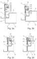
- FIG. 2a Shown is a partial side view of the lamp 2, comprising a lamp element 4, a support unit 3 and as components of the fastening system 1, an element hook 17 as a rigid hooking means 15, arranged on the lighting element 4 and a fastening element 19 arranged on the inside of a side wall 7 of the support unit 3.
- Fig. 2a the lighting element 4 is still without contact with the support unit 3 at a distance below the support unit 3.
- the lighting element 4 executes an upward assembly movement M (first direction of movement), which is oriented orthogonal to the base section 6.
- Fig. 2b the lighting element 4 has been moved upwards so far that the rigid element hook 17 has come into contact with the movable support hook 20.
- the element hook 17 is provided with an inclined thrust surface 22 and the support hook has a suitably inclined first sliding surface 23.
- the two inclined surfaces 22/23 convert the upward assembly movement M of the element hook into a sideways opening movement of the support hook 20, which is a pivoting opening movement (pivoting movement).
- Fig. 2c the sideways movement of the support hook 20 has progressed so far that a reversal point is almost reached.
- the support hook 20 reverses its sideways opening movement and automatically pivots into a Fig. 2d shown hooking engagement 24 with the element hook 17.
- the interlocking mechanism 24 of the Fig. 2d creates an undercut between the support hook 20 and the element hook 17, which counteracts a downward movement of the lighting element 4 in a form-fitting manner.
- the lighting element 4 is fully assembled with the hooking engagement 24 produced and assumes its operating position B, in which it performs its lighting function can fulfill.
- the Figures 2a to 2d also show a locking means 25 for the support hook 20 (locking spring).
- the locking means 25 like the support hook 20, has a spring-elastic property.
- the support hook 20 has a thrust surface 26, which interacts with a sliding element 27 of the locking means 25.
- Fig. 2c a state of elastic deformation of the locking means 25 and of elastic deformation of the support hook 20 can be seen.
- Each elastic deformation stores spring energy.
- the locking means 25 is thus spring-elastically pre-tensioned against the support hook 20.
- the spring-elastically pre-tensioned locking means 25 supports the pivoting back movement of the support hook 20, which brings it into the hooking engagement 24 with the element hook 17.
- a lighting element 4 to attach a support unit 3, it may be sufficient if, for example, on an elongated support unit 3 with opposite side walls 7 and 8, at least one support hook 20 is arranged on only one side wall and the lighting element 4 also has an element hook 17 on only one side. This is possible, for example, if there is close contact between an inner side of the side wall 8 of the support unit 3 and a side section 11 of the lighting element 4, which provides a close guide between the side wall 8 and the side section 11 or provides a slight tilting, in order to achieve a holding effect without having to provide any further interlocking intervention.
- the present example with two interlocking engagements facilitates tool-free disassembly of the lighting element from the support unit.
- Disassembly is basically facilitated by the aforementioned locking means 25 for the movable interlocking means 16, which in this example forms the support hook 20.
- the movable support hook 20 When the movable support hook 20 is in an interlocking engagement 24 with the element hook 17, the support hook 20 can be released from the interlocking engagement 24 and moved into an opening position.
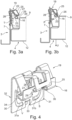
- the locking means is also moved sideways until it reaches a reversal point at which the locking means automatically engages and locks the support hook 20. How the locking occurs is shown in the Figures 3a and 3b which represent a first disassembly step for the tool-free disassembly of the lighting element 4 from the support unit 3.
- the first disassembly step is carried out by a movement T, which starts from the operating position B of the lighting element 4 and takes place in the same first direction of movement as the assembly movement M.
- the disassembly of the lighting element 4 is initiated by a movement in the same direction as the assembly movement M.
- the thrust surface 22 of the element hook 17 acts against a support hook 20 provided second sliding surface 28.
- the second sliding surface 28 also works together with the thrust surface 22 of the element hook 17 according to the principle of inclined planes.
- the support hook 20 is released from the hooking engagement 24 and pivoted in the direction of its opening position.
- the locking means 25 is pivoted sideways in a spring-elastic manner, as in Fig. 3a shown.
- the locking means 25 is further provided with a locking hook 29 and the support hook 20 has a latching area (cf. Fig.4 ) for the locking hook 29.
- the support hook 20 For disassembly, the support hook 20 must be pivoted in the direction of its opening position until the locking means 25, which is also pivoted in the opening direction, reaches a reversal point. As soon as the locking means 25 has passed its reversal point, it reverses the direction of its pivoting movement due to the spring-elastic preload and brings its locking hook 29 into contact with the locking area of the support hook 20, as shown in Fig. 3b In this state, the support hook 20 is locked in its opening position P. The lighting element 4 is released from the hooking engagement and can be freely moved downwards in the direction U, away from the support unit 3, as indicated by a dashed line on the freed element hook 17.
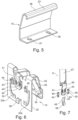
- Fig.4 represents the separate fastening element 19.
- the fastening element 19 comprises a base element 30 with a front side 31 and a back side 32.
- the movable hooking means 16 and the locking means 25, which is provided for locking the movable hooking means 16, are arranged on the front side 31.
- the fastening element 19 has connecting means, which are best described by means of Fig.6 and are explained in more detail below.
- the front 31 there is a protruding Bead 31a and a protruding bead 31b are provided.
- the movable hooking means 16 is adapted to cooperate with a rigid hooking means 15, such as that in Fig.5 shown rigid interlocking means 15.
- the movable hooking means 16 has a locking area 33 for a locking hook 29 of the locking means 25.
- the locking hook 29 is provided with a slot S, which serves to be able to place a tool in it in the locked state in order to be able to release a lock again.
- the movable hooking means 16 is provided with two hooking sections 34 and 35, which are arranged next to one another at a distance.
- the locking area 33 for the locking hook 29 is arranged between the two hooking sections 34 and 35.
- the symmetrical structure of the movable hooking means 16 with two hooking sections 34 and 35 promotes uniform stress. In order to produce the anchoring engagement, both hooking sections 34 and 35 are moved evenly and function synchronously.
- the rigid interlocking means 15 according to Fig.5 has a continuous hook-shaped configuration 36 at a free end, which can interact with both hooking sections 34 and 35 of the movable hooking means 16. At an opposite end, the rigid hooking means 15 has fastening holes 37 and 38, which can be used to fasten the rigid hooking means 15 by means of screws, for example, to the lighting element 4.
- Fig.6 shows the back 32 of the fastening element 19, which is provided with several connecting means.
- the connecting means are for tool-free assembly of the fastening element 19, for example on a side wall 7 of a support unit 3 of a lamp 2.
- the side wall 7 is provided with suitable recesses for the connecting means, as shown below with reference to Fig.7 explained in more detail.
- the beads 31a and 31b protruding on the front side form groove-shaped beads 32a and 32b on the rear side 32.
- the contours 31a/32a and 31b/32b have a stiffening effect for the base element 30.
- the fastening element 19 has a lower connecting means which is designed as a connecting hook 39.
- the connecting hook 39 is arranged centrally on the rear side 32, is designed to be open at the bottom and protrudes from the rear side 32.
- a first upper connecting means has a clamp element 40 which is also designed to be open at the bottom and protrudes from the rear side 32.
- the clamp element 40 is provided with two holes 41 and 42 and in the area of these holes two claw elements 43 and 44 are provided on the rear side 32 which protrude in the direction of the holes 41 and 42.
- second upper connecting means are designed as stop elements 45 and 46, which, in the assembled state, counteract a release of the fastening element 19 from the side wall 7, as can be seen from Fig.7
- the fastening element 19 of the Figures 4 and 6 is manufactured in one piece, preferably punched from a metal sheet and formed into the shape shown.
- Fig.7 shows an enlarged section of the Fig.1 noted details VII, namely that point on the side wall 8 of the support unit 3 on the inside of which a fastening element 21 is attached, which is identical to the fastening element 19 according to the Figures 4 and 6
- the fastening element 21 is mounted without screws or the like and without tools.
- a large recess 47 works together with the clamp element 40.
- the clamp element 40 is designed to be open at the bottom and is attached to a lower edge of the large recess 47.
- the claw elements 43 and 44 lie on the inside of the side wall 8 and ensure hold.
- the side wall 8 has a small recess 48 through which the connecting hook 39 of the fastening element 21 is inserted, the connecting hook 39 gripping a lower edge of the small recess 48.
- two further upper recesses 49 and 50 are provided in the side wall 8.
- stop elements 45 and 46 which protrude on the back 32 of the fastening element, engages in each of these recesses. These stop elements 45 and 46 each form an upper stop which interacts with an upper edge of the upper recess 49 or 50. This counteracts an unwanted upward movement of the fastening element on the side wall, which could lead to an unwanted loosening of the mounted fastening element.
Applications Claiming Priority (1)
| Application Number | Priority Date | Filing Date | Title |
|---|---|---|---|
| DE102022126249.9A DE102022126249A1 (de) | 2022-10-11 | 2022-10-11 | Befestigungssystem für eine Leuchte, Befestigungselement sowie eine Leuchte |
Publications (1)
| Publication Number | Publication Date |
|---|---|
| EP4354017A1 true EP4354017A1 (fr) | 2024-04-17 |
Family
ID=88372216
Family Applications (1)
| Application Number | Title | Priority Date | Filing Date |
|---|---|---|---|
| EP23202979.3A Pending EP4354017A1 (fr) | 2022-10-11 | 2023-10-11 | Système de fixation pour une lampe, élément de fixation et lampe |
Country Status (2)
| Country | Link |
|---|---|
| EP (1) | EP4354017A1 (fr) |
| DE (1) | DE102022126249A1 (fr) |
Citations (6)
| Publication number | Priority date | Publication date | Assignee | Title |
|---|---|---|---|---|
| DE2022009A1 (de) | 1969-05-13 | 1970-11-19 | Novelectric Ag | Anordnung zum loesbaren Verbinden von zwei kanalfoermigen,mit ihrer Laengsoeffnung einander zugekehrten Profilteilen |
| US6386496B1 (en) * | 2000-03-15 | 2002-05-14 | Taiwan Industrial Fastener Corp. | Press-control retaining device |
| DE10360948A1 (de) * | 2003-12-23 | 2005-07-21 | Engel, Hartmut S. | Verschlussmechanismus für Leuchten |
| DE102009004025A1 (de) * | 2009-01-08 | 2010-07-15 | Zumtobel Lighting Gmbh | Leuchte mit zumindest teilweise lösbarem Innenrahmen |
| EP2730835A1 (fr) * | 2010-10-26 | 2014-05-14 | Liangju Wu | Lampe et structure d'installation démontable correspondante |
| DE202014007923U1 (de) * | 2014-01-21 | 2014-10-28 | Bjb Gmbh & Co. Kg | Lampenfassung und Lampensockel, System aus Lampenfassung und Lampensockel |
Family Cites Families (2)
| Publication number | Priority date | Publication date | Assignee | Title |
|---|---|---|---|---|
| DE102004048484A1 (de) | 2004-10-05 | 2006-04-13 | Engel, Hartmut S. | Verschlussmechanismus für Leuchten |
| DE102005032265B4 (de) | 2005-07-04 | 2009-11-19 | Siteco Beleuchtungstechnik Gmbh | Rastbefestigung von Leuchtenbauteilen |
-
2022
- 2022-10-11 DE DE102022126249.9A patent/DE102022126249A1/de active Pending
-
2023
- 2023-10-11 EP EP23202979.3A patent/EP4354017A1/fr active Pending
Patent Citations (6)
| Publication number | Priority date | Publication date | Assignee | Title |
|---|---|---|---|---|
| DE2022009A1 (de) | 1969-05-13 | 1970-11-19 | Novelectric Ag | Anordnung zum loesbaren Verbinden von zwei kanalfoermigen,mit ihrer Laengsoeffnung einander zugekehrten Profilteilen |
| US6386496B1 (en) * | 2000-03-15 | 2002-05-14 | Taiwan Industrial Fastener Corp. | Press-control retaining device |
| DE10360948A1 (de) * | 2003-12-23 | 2005-07-21 | Engel, Hartmut S. | Verschlussmechanismus für Leuchten |
| DE102009004025A1 (de) * | 2009-01-08 | 2010-07-15 | Zumtobel Lighting Gmbh | Leuchte mit zumindest teilweise lösbarem Innenrahmen |
| EP2730835A1 (fr) * | 2010-10-26 | 2014-05-14 | Liangju Wu | Lampe et structure d'installation démontable correspondante |
| DE202014007923U1 (de) * | 2014-01-21 | 2014-10-28 | Bjb Gmbh & Co. Kg | Lampenfassung und Lampensockel, System aus Lampenfassung und Lampensockel |
Also Published As
| Publication number | Publication date |
|---|---|
| DE102022126249A1 (de) | 2024-04-11 |
Similar Documents
| Publication | Publication Date | Title |
|---|---|---|
| EP2966339B1 (fr) | Éclairage, systeme pour un plafond lumineux a grille, procede de montage d'un eclairage, procede de demontage d'un eclairage et outil de demontage | |
| DE102011083993B4 (de) | Lichtband | |
| EP2644984B1 (fr) | Verrouillage pour un couvercle de lampe | |
| DE102009033938B4 (de) | Wohndachfenster sowie Verfahren zum Befestigen eines Abdeckblechs | |
| DE19837367A1 (de) | Rahmenprofil für einen Schaltschrank | |
| DE102019109676A1 (de) | Haltefeder für Leuchte | |
| EP4354017A1 (fr) | Système de fixation pour une lampe, élément de fixation et lampe | |
| EP3608588B1 (fr) | Ressort de maintien pour luminaire | |
| EP0795719B1 (fr) | Unité modulaire pour illumination | |
| EP2754803B1 (fr) | Crémone de fenêtre ou de porte et tringle pour une telle crémone | |
| EP3209934B1 (fr) | Plafonnier à spots lumineux | |
| EP3462084A1 (fr) | Lampe à del | |
| EP1267119B1 (fr) | Lamp en saillie | |
| DE10234459B4 (de) | Verbindungselement zum Befestigen eines optischen Leuchtenbauteils an einer Leuchte und Leuchte | |
| EP3156716B1 (fr) | Lampe allongée | |
| WO2015074933A1 (fr) | Dispositif de retenue pour boîtier et procédé de montage du boîtier à l'aide du dispositif de retenue | |
| DE102006056599B3 (de) | Faltenbalg sowie Verfahren zur Montage eines Faltenbalgs an einem Sitzrahmen | |
| EP0829677A1 (fr) | Armature lumineuse pour locaux humides | |
| WO2002061331A1 (fr) | Dispositif d'eclairage equipe d'un moyen de fixation | |
| EP0528198B1 (fr) | Lamelle de fixation d'une tôle pliée à un écran à lamelles d'un dispositif d'éclairage | |
| DE102023109104B3 (de) | Vorrichtung zur Ertüchtigung von Leuchten | |
| DE102006017043A1 (de) | Verbindungstechnik von Lamellen in Leuchtenrastern | |
| DE102019109662A1 (de) | Haltefeder | |
| CH610989A5 (en) | Connection for structural parts | |
| DE102019121529A1 (de) | Längliche Leuchte |
Legal Events
| Date | Code | Title | Description |
|---|---|---|---|
| PUAI | Public reference made under article 153(3) epc to a published international application that has entered the european phase |
Free format text: ORIGINAL CODE: 0009012 |
|
| STAA | Information on the status of an ep patent application or granted ep patent |
Free format text: STATUS: THE APPLICATION HAS BEEN PUBLISHED |
|
| AK | Designated contracting states |
Kind code of ref document: A1 Designated state(s): AL AT BE BG CH CY CZ DE DK EE ES FI FR GB GR HR HU IE IS IT LI LT LU LV MC ME MK MT NL NO PL PT RO RS SE SI SK SM TR |