EP4350119B1 - Unterwasser-bohrvorrichtung und verfahren zum erstellen einer verrohrung unter wasser - Google Patents
Unterwasser-bohrvorrichtung und verfahren zum erstellen einer verrohrung unter wasser Download PDFInfo
- Publication number
- EP4350119B1 EP4350119B1 EP22200104.2A EP22200104A EP4350119B1 EP 4350119 B1 EP4350119 B1 EP 4350119B1 EP 22200104 A EP22200104 A EP 22200104A EP 4350119 B1 EP4350119 B1 EP 4350119B1
- Authority
- EP
- European Patent Office
- Prior art keywords
- support tube
- platform
- rig
- hole drilling
- drilling apparatus
- Prior art date
- Legal status (The legal status is an assumption and is not a legal conclusion. Google has not performed a legal analysis and makes no representation as to the accuracy of the status listed.)
- Active
Links
Images

Classifications
-
- E—FIXED CONSTRUCTIONS
- E21—EARTH OR ROCK DRILLING; MINING
- E21B—EARTH OR ROCK DRILLING; OBTAINING OIL, GAS, WATER, SOLUBLE OR MELTABLE MATERIALS OR A SLURRY OF MINERALS FROM WELLS
- E21B41/00—Equipment or details not covered by groups E21B15/00 - E21B40/00
- E21B41/08—Underwater guide bases, e.g. drilling templates; Levelling thereof
-
- E—FIXED CONSTRUCTIONS
- E02—HYDRAULIC ENGINEERING; FOUNDATIONS; SOIL SHIFTING
- E02D—FOUNDATIONS; EXCAVATIONS; EMBANKMENTS; UNDERGROUND OR UNDERWATER STRUCTURES
- E02D7/00—Methods or apparatus for placing sheet pile bulkheads, piles, mouldpipes, or other moulds
- E02D7/28—Placing of hollow pipes or mould pipes by means arranged inside the piles or pipes
-
- E—FIXED CONSTRUCTIONS
- E21—EARTH OR ROCK DRILLING; MINING
- E21B—EARTH OR ROCK DRILLING; OBTAINING OIL, GAS, WATER, SOLUBLE OR MELTABLE MATERIALS OR A SLURRY OF MINERALS FROM WELLS
- E21B15/00—Supports for the drilling machine, e.g. derricks or masts
- E21B15/003—Supports for the drilling machine, e.g. derricks or masts adapted to be moved on their substructure, e.g. with skidding means; adapted to drill a plurality of wells
-
- E—FIXED CONSTRUCTIONS
- E21—EARTH OR ROCK DRILLING; MINING
- E21B—EARTH OR ROCK DRILLING; OBTAINING OIL, GAS, WATER, SOLUBLE OR MELTABLE MATERIALS OR A SLURRY OF MINERALS FROM WELLS
- E21B15/00—Supports for the drilling machine, e.g. derricks or masts
- E21B15/02—Supports for the drilling machine, e.g. derricks or masts specially adapted for underwater drilling
-
- E—FIXED CONSTRUCTIONS
- E21—EARTH OR ROCK DRILLING; MINING
- E21B—EARTH OR ROCK DRILLING; OBTAINING OIL, GAS, WATER, SOLUBLE OR MELTABLE MATERIALS OR A SLURRY OF MINERALS FROM WELLS
- E21B19/00—Handling rods, casings, tubes or the like outside the borehole, e.g. in the derrick; Apparatus for feeding the rods or cables
- E21B19/002—Handling rods, casings, tubes or the like outside the borehole, e.g. in the derrick; Apparatus for feeding the rods or cables specially adapted for underwater drilling
-
- E—FIXED CONSTRUCTIONS
- E21—EARTH OR ROCK DRILLING; MINING
- E21B—EARTH OR ROCK DRILLING; OBTAINING OIL, GAS, WATER, SOLUBLE OR MELTABLE MATERIALS OR A SLURRY OF MINERALS FROM WELLS
- E21B19/00—Handling rods, casings, tubes or the like outside the borehole, e.g. in the derrick; Apparatus for feeding the rods or cables
- E21B19/08—Apparatus for feeding the rods or cables; Apparatus for increasing or decreasing the pressure on the drilling tool; Apparatus for counterbalancing the weight of the rods
- E21B19/086—Apparatus for feeding the rods or cables; Apparatus for increasing or decreasing the pressure on the drilling tool; Apparatus for counterbalancing the weight of the rods with a fluid-actuated cylinder
-
- E—FIXED CONSTRUCTIONS
- E21—EARTH OR ROCK DRILLING; MINING
- E21B—EARTH OR ROCK DRILLING; OBTAINING OIL, GAS, WATER, SOLUBLE OR MELTABLE MATERIALS OR A SLURRY OF MINERALS FROM WELLS
- E21B7/00—Special methods or apparatus for drilling
- E21B7/12—Underwater drilling
-
- E—FIXED CONSTRUCTIONS
- E21—EARTH OR ROCK DRILLING; MINING
- E21B—EARTH OR ROCK DRILLING; OBTAINING OIL, GAS, WATER, SOLUBLE OR MELTABLE MATERIALS OR A SLURRY OF MINERALS FROM WELLS
- E21B7/00—Special methods or apparatus for drilling
- E21B7/12—Underwater drilling
- E21B7/124—Underwater drilling with underwater tool drive prime mover, e.g. portable drilling rigs for use on underwater floors
-
- E—FIXED CONSTRUCTIONS
- E21—EARTH OR ROCK DRILLING; MINING
- E21B—EARTH OR ROCK DRILLING; OBTAINING OIL, GAS, WATER, SOLUBLE OR MELTABLE MATERIALS OR A SLURRY OF MINERALS FROM WELLS
- E21B7/00—Special methods or apparatus for drilling
- E21B7/20—Driving or forcing casings or pipes into boreholes, e.g. sinking; Simultaneously drilling and casing boreholes
- E21B7/208—Driving or forcing casings or pipes into boreholes, e.g. sinking; Simultaneously drilling and casing boreholes using down-hole drives
-
- E—FIXED CONSTRUCTIONS
- E02—HYDRAULIC ENGINEERING; FOUNDATIONS; SOIL SHIFTING
- E02D—FOUNDATIONS; EXCAVATIONS; EMBANKMENTS; UNDERGROUND OR UNDERWATER STRUCTURES
- E02D15/00—Handling building or like materials for hydraulic engineering or foundations
- E02D15/08—Sinking workpieces into water or soil inasmuch as not provided for elsewhere
-
- E—FIXED CONSTRUCTIONS
- E02—HYDRAULIC ENGINEERING; FOUNDATIONS; SOIL SHIFTING
- E02D—FOUNDATIONS; EXCAVATIONS; EMBANKMENTS; UNDERGROUND OR UNDERWATER STRUCTURES
- E02D27/00—Foundations as substructures
- E02D27/32—Foundations for special purposes
- E02D27/52—Submerged foundations, i.e. submerged in open water
- E02D27/525—Submerged foundations, i.e. submerged in open water using elements penetrating the underwater ground
Definitions
- the invention relates to an underwater drilling device for creating a cased borehole under water with a lowerable platform, according to claim 1.
- the invention further relates to a method for creating a cased borehole under water with such an underwater drilling device, according to claim 12.
- a drilling device and a method for creating a foundation for a structure in water are disclosed.
- a guide device is placed on the surface of a body of water.
- a support pipe is arranged in the guide device.
- a drilling rig which is inserted into the support pipe, a bore is created into which the support pipe is lowered.
- a foundation element can be inserted into the support pipe.
- the support pipe is then withdrawn, filling any space between the bore wall and the inserted foundation element.
- a device and method for constructing an underwater foundation are disclosed. This also involves inserting a support pipe into the ground, into which a down-the-hole drilling rig is positioned.
- the down-the-hole drilling rig removes soil material, allowing the surrounding support pipe to be pushed axially.
- EP 3 333 324 A1 Another known device and method for constructing a foundation for a structure in water is known from EP 3 333 324 A1 out.
- the EP 2 562 348 A1 or the EP 2 527 539 A1 disclose the preamble of claim 1.
- the invention is based on the object of specifying a drilling device and a method with which a cased borehole under water can be created particularly efficiently.
- the object is achieved, on the one hand, by an underwater drilling device having the features of claim 1 and, on the other hand, by a method having the features of claim 12.
- Preferred embodiments of the invention are specified in the dependent claims.
- a first aspect of the invention is to provide at least one pipe drive for rotatingly driving the support pipe on the lowerable platform in an underwater drilling device, wherein the pipe drive is designed to rotately insert the support pipe into the waterbed.
- the underwater drilling device with the pipe drive is designed such that a down-the-hole drilling rig arranged in the support pipe is clamped to the support pipe when the support pipe is rotated, so that the support pipe rotates with the rotating support pipe.
- a down-the-hole drilling rig arranged in the support pipe is clamped to the support pipe when the support pipe is rotated, so that the support pipe rotates with the rotating support pipe.
- either the support pipe or the drill head of the drilling rig can advance. While the drill head is rotating, the drilling rig can be clamped to the stationary support pipe. After a drilling step with the drill head of the drilling rig, the support pipe can be inserted into the ground by a further rotational advance, with the down-the-hole drilling rig remaining connected to the support pipe in a rotationally fixed manner.
- the drill head can be driven to rotate relative to the device base at the same time, in the same or the opposite direction of rotation as the support pipe.
- the tubular drive on the lowerable platform can be configured in any suitable manner for rotating the support tube.
- a preferred embodiment of the invention consists in the fact that, to form the tubular drive on the platform, a collet device for clamping the support tube is arranged on its outer side in a rotatable or pivotable manner and axially movable, wherein a torque of the tubular drive can be transmitted to the support tube.
- the pipe drive can be designed similarly to a casing rigging device, with a collet chuck allowing a releasable grip on the outside of the support pipe.
- the collet chuck can be rotated around the pipe's longitudinal axis, preferably using hydraulic cylinders.
- the tubular drive is designed to transmit a continuous rotary movement to the support tube.
- This allows for a continuous rotary drive.
- two or more collets, each with a rotation cylinder, can be provided, with each arrangement with a collet performing a specific rotation through a predetermined angular range. Through coordinated, sequential rotation by at least two such arrangements, a continuous or quasi-continuous rotation of the support tube can be achieved.
- the tube drive is designed to transmit an oscillating rotary movement to the support tube.
- This oscillating or step-by-step rotary movement can be achieved, in particular, by an arrangement with a single collet device.
- the down-the-hole drilling rig can be suspended in the support tube via a suspension cable, so that the feed force can be applied solely by the weight of the down-the-hole drilling rig.
- the down-the-hole drilling rig has an axial feed device with which the drill head can be axially displaced relative to the device base body.
- the device base body can have a frame structure which can be rotationally fixed in the inner wall of the support tube, preferably via radially extendable hydraulic clamping cylinders.
- the feed device can have one or more hydraulic actuating cylinders aligned in the axial direction. This allows a rotationally driven drill head to be axially displaced relative to the device base body.
- the drill drive which can preferably have one or more hydraulic rotary motors, can be axially fixed to the base body, with a drill drive shaft being axially telescopic by means of appropriate spline teeth or another suitable configuration. This allows torque to be transmitted from the drill drive to the axially movable drill head.
- the feed device can be designed in any suitable manner. According to one embodiment of the invention, it is particularly advantageous for the feed device to have at least one hydraulic feed cylinder.
- the feed cylinder can be a single-acting or double-acting actuating cylinder.
- the platform can be designed as a template for a predetermined arrangement of support tubes in a body of water.
- a separate down-the-hole drilling rig can be arranged in each support tube.
- a single down-the-hole drilling rig can be provided. which is initially inserted into a first support tube to create a first borehole. After creating the first borehole, the down-the-hole drilling rig can be released and withdrawn from the first support tube and inserted into a second support tube to create a second cased borehole. This can be repeated as many times as necessary.
- Pipe drives are preferably arranged on the platform, corresponding to the number of support tubes planned.
- the down-the-hole drilling rig is connected to a supply unit, in particular a supply vessel, on the water surface via one or more lines, in particular a so-called umbilical.
- Energy in particular electrical energy and/or hydraulic energy, is transmitted via the one or more lines.
- the at least one line can be connected to the down-the-hole drilling rig via a corresponding rotary coupling in an upper area of the down-the-hole drilling rig.
- a so-called rotary union can be provided, in particular, for the passage of hydraulic fluid.
- a simplified embodiment of the invention for preventing twisting of the at least one cable consists in arranging at least one upper clamping device on the tool base and at least one lower clamping device on the drill head. This allows for targeted, alternating clamping of the drill head and/or the tool base.
- the at least one lower clamping device on the drill head is radially extended and the drill head is clamped to the support tube, and the at least one upper clamping device on the tool body is radially retracted and released from the support tube.
- the rotary drive can be decoupled from the drill head, or a freewheel can be selected.
- the device base body is clamped and fixed to the support tube so that the down-the-hole drilling device is screwed in with the support tube.
- a further preferred embodiment of the invention consists in that the platform on the waterbed has a supply device which is connected to a surface supply unit via at least one main supply line, and in that the at least one pipe drive and the at least one down-the-hole drilling rig are connected to the supply device of the platform for energy supply, in particular via supply lines.
- the supply device on the platform can preferably store energy to a certain extent, for example electrical energy through provided accumulators or hydraulic energy through corresponding pressure accumulators.
- the platform can thus be operated autonomously for a certain period of time, which may be necessary, for example, in harsh weather conditions and the associated disconnection of the main supply line.
- the supply device on the platform is connected to a surface supply unit via the preferably detachable main supply line.
- the surface supply unit can in particular be a ship.
- the invention further comprises a method for creating a cased borehole underwater using an underwater drilling device according to the invention, wherein at least one support pipe is arranged on a platform of the underwater drilling device, at least one down-the-hole drilling device in which at least one support pipe is arranged, the platform is lowered onto a body of water, the at least one support pipe is driven in rotation via a pipe drive on the platform and drilled into the body of water, prior to and/or following drilling of the support pipe, the drill head of the down-the-hole drilling device arranged in the support pipe is driven in rotation and is used to create the borehole in the body of water drilled while the support tube is held non-rotatably on the platform, and when the support tube is driven in rotation, the down-the-hole drilling rig remains in the support tube and is axially clamped to it.
- the method can be carried out in particular with the underwater drilling device according to the invention described above.
- the advantages described in this context can be achieved.
- the method according to the invention comprises the method steps specified in claim 1, but is not limited to a specific sequence of method steps. Individual method steps can also be carried out before or after other method steps.
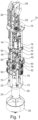
- FIG. 1 to 4 An exemplary embodiment of a down-the-hole drilling rig 10 for forming an underwater drilling device 100 according to the invention is shown.
- the down-the-hole drilling rig 10 has a framework-like device base body 12, which comprises a first annular frame section 14.
- a drilling drive 40 Arranged on the upper side of this plate-like first frame section 14 is a drilling drive 40, which in the illustrated exemplary embodiment is formed by three hydraulic rotary drives 42, which are arranged evenly distributed around a longitudinal or drilling axis of the down-the-hole drilling rig 10.
- the clamping device 50 Attached to the underside of the first frame section 14 is the clamping device 50, which is designed for radially clamping and fixing the down-the-hole drilling device 10 against a wall of a support tube and/or a borehole.
- the annular clamping device 50 has six radially directed clamping cylinders (not shown), on the outside of which stamp-like clamping plates 52 are attached.
- the clamping cylinders with the clamping plates 52 are arranged evenly distributed around the longitudinal or drilling axis of the down-the-hole drilling device 10.
- An upper frame section 15 is arranged at the upper end of the frame 12. Between the upper frame section 15 and the underlying first frame section 14 is arranged a plate-shaped, ring-like intermediate section 16, which is connected via vertically directed connecting struts 18 on the one hand to the first frame section 14 and on the other hand upwards to the upper frame section 15.
- a connecting device 28 for a cable suspension of the down-the-hole drilling rig 10 is arranged centrally on an upper side of the upper frame section 15, as are two line feeds 29 arranged laterally thereon.
- the line feeds 29 serve, on the one hand, to feed a hydraulic hose line and, on the other hand, to feed and hold a drilling slurry discharge line.
- Additional supplies for compressed air for an air lifting process as well as electrical power and data lines as well as other supply lines may be provided.
- Control components 19 can be arranged on the plate-like intermediate section 16.
- the upper region of the device base body 12, comprising the first frame section 14, the upper frame section 15, and the intermediate section 16, can be constructed in a modular manner, so that the down-the-hole drilling device 10 can be easily adapted to different borehole sizes and areas of application.
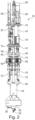
- the feed device 70 with hydraulic feed cylinders 72 is arranged below the clamping device 50 on the first frame section 14.
- the feed cylinders 72 are fastened to the first frame section 14 with their cylinder housings.
- the feed cylinders 72 are connected to the extendable cylinder piston. on the other hand, hinged to a second annular, plate-like second frame section 20.
- the annular second frame section 20 is attached to an outer side of a tubular bearing sleeve 24, in which a tubular drill string 38, which is only partially inserted into the Figures 3 and 4 is visible, rotatable but axially fixed.
- a drill head 30 is attached to the lower end of the drill string 38.
- the drill head 30 has a central pilot tip 32 and radially directed removal elements 34, which are designed to remove soil material.
- the second frame section 20 is mounted so as to be axially adjustable relative to the first frame section 14.
- a drive shaft 44 of the drill drive 40 extends into the tubular drill string 38.
- the drive shaft 44 has outer, axially extending drive strips 46, which interact with corresponding inner drive strips on the inside of the tubular drill string 38 to transmit torque.
- the drive shaft 44 drives the drill string 38 with the drill head 30 in rotation, allowing it to remove soil material.
- the down-the-hole drilling rig 10 is shown in a state in which the drill head 30 is axially retracted.
- the down-the-hole drilling rig 10 can be fixed in the borehole via the clamping device 50 by radially extending the clamping plates 52 against a support tube.
- the feed device 70 can be actuated, whereby the feed cylinders 72 extend downward.
- the second frame section 20 with the bearing sleeve 24 and the drill head 30 mounted thereon can be moved downward in order to effect a corresponding advance during drilling.
- the drill head 30 and/or the down-the-hole drilling rig can be clamped or fixed when the support tube 8 is screwed in.
- the tensioning by the tensioning device 50 can be released by retracting the tensioning plates 52.
- the upper area of the device base body 12 can be guided downwards by retracting the feed cylinders 72 and releasing a support cable attached to the connecting device 28 until the axially retracted state is reached according to the Figures 1 and 2 is reached again.
- a further drilling step can be performed by clamping the tool base body 12 using the clamping device 50.
- the clamping plates 52 can be extended radially and remain fixed to the support tube 8.
- the support tube 8 can then be screwed into the ground and guided.
- the feed cylinders 72 can be retracted during this process.
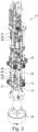
- Soil material accumulating during drilling can be removed through the frame 12 via the hollow drill string 38 and the hollow drive shaft 44 by means of a suction pump 36 as a conveying device 35 and transported outside the borehole via a partially illustrated conveying line 37.
- the second frame section 20 with the bearing sleeve 24 can have a third frame section 27, which can be mounted for linear displacement via linear guides 26 fixedly attached to the first frame section 14 and directed downwards.
- the guides 26 can absorb torsional forces in the circumferential direction, so that the feed cylinders 72 are relieved of transverse forces.
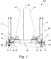
- an underwater drilling device 100 has a lowerable platform 80 with a working platform 82, which is suspended from a cable arrangement 97, only partially shown, and which can be lowered and set down onto a body of water 5 via this cable arrangement 97 with adjustable feet 88.
- FIG. 5 As shown, several support tubes 8 with in-hole drilling devices 10 inserted therein can be arranged on the working platform 82, of which in the side view in Fig. 5 two down-the-hole drilling rigs 10 can be seen.
- Four down-the-hole drilling rigs 10 can be arranged at the corners of the working platform 82, which is designed as a geometric rectangle, or three down-the-hole drilling rigs 10 can be arranged at the corners of the working platform, which is designed as an equilateral triangle.
- the down-hole drilling rigs 10 are essentially of the same design, as previously described.
- the down-hole drilling rig 10 is used to insert a support pipe 8 into the waterbed 5.
- a sleeve-like linear guide 84 and a pipe drive 85 for each down-hole drilling rig 10 or each borehole are arranged on the working platform 82.
- the linear guide 84 guides the support pipe 8 vertically displaceably on the working platform 2.
- the drilling unit 100 further comprises a A collet device 86 for the rotationally fixed fixing, rotation, and/or axial displacement of the support tube 8 on the work platform 82. This collet device 86 is arranged below the linear guide 84 on the work platform 82.
- the collet device 86 can be designed, for example, as a hydraulic clamping device and also has means for axially fixing the support tube 8, i.e., means for securing it against displacement in the vertical direction.
- the collet device 86 can thus ensure that the support tube 8 maintains its rotational position, as well as its axial position relative to the work platform 82, when the work platform 82 is lowered, but also during the drilling process.
- the down-the-hole drilling rig 10 is inserted.
- a drill head 30 designed as a full-cut drill head or another suitable drill head equipped with rolling bits can be provided.
- the drill head 30 can protrude at the lower end of the support tube 8 so that the drill head 30 can remove soil material below the support tube 8.
- the support tube 8 can be rotated and axially pushed along with the down-the-hole drilling rig 10 via the collet device 86.
- the down-the-hole drilling rig 10 can be clamped in the support tube 8 and thus moved along with it.
- Energy can be supplied via a main supply line 92 to a central supply device 90 on the work platform 82.
Landscapes
- Engineering & Computer Science (AREA)
- Life Sciences & Earth Sciences (AREA)
- Mining & Mineral Resources (AREA)
- Geology (AREA)
- General Life Sciences & Earth Sciences (AREA)
- Environmental & Geological Engineering (AREA)
- Fluid Mechanics (AREA)
- Physics & Mathematics (AREA)
- Geochemistry & Mineralogy (AREA)
- Mechanical Engineering (AREA)
- Paleontology (AREA)
- Civil Engineering (AREA)
- General Engineering & Computer Science (AREA)
- Structural Engineering (AREA)
- Earth Drilling (AREA)
Priority Applications (6)
| Application Number | Priority Date | Filing Date | Title |
|---|---|---|---|
| EP22200104.2A EP4350119B1 (de) | 2022-10-06 | 2022-10-06 | Unterwasser-bohrvorrichtung und verfahren zum erstellen einer verrohrung unter wasser |
| PL22200104.2T PL4350119T3 (pl) | 2022-10-06 | 2022-10-06 | Podwodne urządzenie wiertnicze i sposób wykonywania orurowanego otworu wiertniczego pod wodą |
| ES22200104T ES3032517T3 (en) | 2022-10-06 | 2022-10-06 | Underwater drilling apparatus and method for constructing a casing under water |
| US18/471,972 US12146408B2 (en) | 2022-10-06 | 2023-09-21 | Underwater drilling apparatus and method for creating a cased borehole underwater |
| CN202311257897.1A CN117846494A (zh) | 2022-10-06 | 2023-09-27 | 用于在水下产生套管式井孔的水下钻探设备和方法 |
| JP2023164920A JP7700191B2 (ja) | 2022-10-06 | 2023-09-27 | 水中掘削装置および水中でケーシングされた掘削孔を形成する方法 |
Applications Claiming Priority (1)
| Application Number | Priority Date | Filing Date | Title |
|---|---|---|---|
| EP22200104.2A EP4350119B1 (de) | 2022-10-06 | 2022-10-06 | Unterwasser-bohrvorrichtung und verfahren zum erstellen einer verrohrung unter wasser |
Publications (3)
| Publication Number | Publication Date |
|---|---|
| EP4350119A1 EP4350119A1 (de) | 2024-04-10 |
| EP4350119B1 true EP4350119B1 (de) | 2025-04-02 |
| EP4350119C0 EP4350119C0 (de) | 2025-04-02 |
Family
ID=83688692
Family Applications (1)
| Application Number | Title | Priority Date | Filing Date |
|---|---|---|---|
| EP22200104.2A Active EP4350119B1 (de) | 2022-10-06 | 2022-10-06 | Unterwasser-bohrvorrichtung und verfahren zum erstellen einer verrohrung unter wasser |
Country Status (6)
| Country | Link |
|---|---|
| US (1) | US12146408B2 (pl) |
| EP (1) | EP4350119B1 (pl) |
| JP (1) | JP7700191B2 (pl) |
| CN (1) | CN117846494A (pl) |
| ES (1) | ES3032517T3 (pl) |
| PL (1) | PL4350119T3 (pl) |
Family Cites Families (12)
| Publication number | Priority date | Publication date | Assignee | Title |
|---|---|---|---|---|
| JPS5644875Y2 (pl) * | 1978-01-18 | 1981-10-20 | ||
| JPH0971945A (ja) * | 1995-09-06 | 1997-03-18 | Mitsui Miike Mach Co Ltd | ケーソン工法における掘削方法および掘削装置 |
| JP4230231B2 (ja) * | 2003-01-22 | 2009-02-25 | 清水建設株式会社 | 水中連続コア削孔工法 |
| JP2006219911A (ja) | 2005-02-10 | 2006-08-24 | Ohbayashi Corp | 場所打ちコンクリート杭の杭坑拡幅装置及び方法 |
| EP2322724B1 (de) * | 2009-11-17 | 2012-04-18 | BAUER Maschinen GmbH | Unterwasserbohranordnung und Verfahren zum Einbringen eines rohrförmigen Gründungselements in den Gewässergrund |
| JP4714792B1 (ja) * | 2010-07-01 | 2011-06-29 | 八州建機株式会社 | バケット式削孔装置 |
| DK2527539T3 (da) * | 2011-05-27 | 2013-09-30 | Bauer Maschinen Gmbh | Undervands-boreindretning og fremgangsmåde til anbringelse af et funderingselement i en havbund |
| EP2562310B1 (de) * | 2011-08-23 | 2016-07-20 | BAUER Maschinen GmbH | Unterwasser-Bohranordnung und Verfahren zum Erstellen einer Bohrung in einem Gewässergrund |
| EP2562348B1 (de) * | 2011-08-23 | 2017-10-04 | BAUER Maschinen GmbH | Unterwasser-Bohranordnung und Verfahren zum Erstellen einer Bohrung |
| BE1020365A4 (nl) | 2012-01-02 | 2013-08-06 | Geosea N V | Inrichting en werkwijze voor het boren van schachten in een uit rots, klei en/of aanverwante materialen bestaande ondergrond. |
| DE102014002968A1 (de) * | 2014-03-06 | 2015-09-10 | Herrenknecht Ag | Bohrvorrichtung zum Erstellen einer Bohrung und System zum Positionieren der Bohrvorrichtung |
| DK2930275T3 (en) | 2014-04-08 | 2018-04-03 | Herrenknecht Ag | System and method for making a foundation for a building in water |
-
2022
- 2022-10-06 PL PL22200104.2T patent/PL4350119T3/pl unknown
- 2022-10-06 EP EP22200104.2A patent/EP4350119B1/de active Active
- 2022-10-06 ES ES22200104T patent/ES3032517T3/es active Active
-
2023
- 2023-09-21 US US18/471,972 patent/US12146408B2/en active Active
- 2023-09-27 JP JP2023164920A patent/JP7700191B2/ja active Active
- 2023-09-27 CN CN202311257897.1A patent/CN117846494A/zh active Pending
Also Published As
| Publication number | Publication date |
|---|---|
| US20240117681A1 (en) | 2024-04-11 |
| ES3032517T3 (en) | 2025-07-21 |
| PL4350119T3 (pl) | 2025-06-16 |
| EP4350119A1 (de) | 2024-04-10 |
| JP7700191B2 (ja) | 2025-06-30 |
| EP4350119C0 (de) | 2025-04-02 |
| CN117846494A (zh) | 2024-04-09 |
| JP2024055790A (ja) | 2024-04-18 |
| US12146408B2 (en) | 2024-11-19 |
Similar Documents
| Publication | Publication Date | Title |
|---|---|---|
| DE3114612C2 (de) | Bohrvorrichtung für Hartgestein | |
| EP2527539B1 (de) | Unterwasser-Bohranordnung und Verfahren zum Einbringen eines Gründungselementes in einen Gewässergrund | |
| EP2728104B1 (de) | Verfahren zum erstellen einer horizontalbohrung im erdreich und horizontalbohrvorrichtung | |
| EP2562348B1 (de) | Unterwasser-Bohranordnung und Verfahren zum Erstellen einer Bohrung | |
| DE2542432A1 (de) | Drehwerk fuer eine bohranlage und verfahren zum bohren und anschliessenden ausbauen eines bohrgestaenges | |
| EP2322724B1 (de) | Unterwasserbohranordnung und Verfahren zum Einbringen eines rohrförmigen Gründungselements in den Gewässergrund | |
| EP2553202B1 (de) | Verfahren zum betrieb einer horizontalbohrvorrichtung und horizontalbohrvorrichtung | |
| DE2726445B2 (de) | Streckenvortriebsmaschine | |
| EP1580398B1 (de) | Verfahren und Vorrichtung zum Tiefbau | |
| EP2553203B1 (de) | Horizontalbohrvorrichtung | |
| EP2843138B1 (de) | Verfahren und Vorrichtung zur Herstellung von Bodenpfählen | |
| EP0825326B1 (de) | Verfahren und Vorrichtung zum Horizontalbohren und zum Handhaben von Bohrstangen | |
| DE102011000320A1 (de) | Bohranlage zum Durchführen von Bohrungen im Erdreich | |
| DE4015492A1 (de) | Vollschnitt-vortriebsmaschine fuer den strecken- und tunnelvortrieb u. dgl., insbesondere fuer den schildvortrieb von bergbaustrecken | |
| EP0819819B1 (de) | Fräskopf, Bohrvorrichtung sowie Vorrichtung und Verfahren zum Meeresbodenbohren | |
| DE3726472C2 (pl) | ||
| EP4350119B1 (de) | Unterwasser-bohrvorrichtung und verfahren zum erstellen einer verrohrung unter wasser | |
| DE3612762A1 (de) | Teleskopierbares bohrgeraet | |
| DE2815149C3 (de) | Verfahren und Vorrichtung zum Hochbrechen eines Schachtes durch Aufwärtsbohren aus dem Vollen | |
| DE4308856C1 (de) | Verfahren und Bohrgerät zur Herstellung einer verrohrten Tiefbohrung, insbesondere für Pfahlgründungen | |
| EP4372202B1 (de) | Im-loch-bohrgerät und verfahren zum erstellen einer bohrung im boden | |
| EP3862528B1 (de) | Imloch-bohrgerät und verfahren zum erstellen einer bohrung | |
| DE3324757C2 (de) | Vorrichtung zum Bohren und Verrohren eines vertikalen Bohrloches | |
| DE2829834A1 (de) | Steinbohrmeissel und verfahren zu seiner anwendung | |
| DE60011244T2 (de) | Bohrer zur herstellung von weitdurchmesser und grosstiefen bohrlöchern sowie verfahren zur durchführung von solchen bohrlöchern |
Legal Events
| Date | Code | Title | Description |
|---|---|---|---|
| PUAI | Public reference made under article 153(3) epc to a published international application that has entered the european phase |
Free format text: ORIGINAL CODE: 0009012 |
|
| STAA | Information on the status of an ep patent application or granted ep patent |
Free format text: STATUS: REQUEST FOR EXAMINATION WAS MADE |
|
| STAA | Information on the status of an ep patent application or granted ep patent |
Free format text: STATUS: EXAMINATION IS IN PROGRESS |
|
| 17P | Request for examination filed |
Effective date: 20230905 |
|
| AK | Designated contracting states |
Kind code of ref document: A1 Designated state(s): AL AT BE BG CH CY CZ DE DK EE ES FI FR GB GR HR HU IE IS IT LI LT LU LV MC ME MK MT NL NO PL PT RO RS SE SI SK SM TR |
|
| 17Q | First examination report despatched |
Effective date: 20240314 |
|
| GRAP | Despatch of communication of intention to grant a patent |
Free format text: ORIGINAL CODE: EPIDOSNIGR1 |
|
| STAA | Information on the status of an ep patent application or granted ep patent |
Free format text: STATUS: GRANT OF PATENT IS INTENDED |
|
| RIC1 | Information provided on ipc code assigned before grant |
Ipc: E21B 7/12 20060101ALI20241007BHEP Ipc: E02D 27/52 20060101ALI20241007BHEP Ipc: E02D 15/08 20060101ALI20241007BHEP Ipc: E21B 7/124 20060101ALI20241007BHEP Ipc: E02D 13/04 20060101ALI20241007BHEP Ipc: E02D 7/28 20060101ALI20241007BHEP Ipc: E21B 7/20 20060101ALI20241007BHEP Ipc: E21B 41/08 20060101AFI20241007BHEP |
|
| INTG | Intention to grant announced |
Effective date: 20241030 |
|
| GRAS | Grant fee paid |
Free format text: ORIGINAL CODE: EPIDOSNIGR3 |
|
| GRAA | (expected) grant |
Free format text: ORIGINAL CODE: 0009210 |
|
| STAA | Information on the status of an ep patent application or granted ep patent |
Free format text: STATUS: THE PATENT HAS BEEN GRANTED |
|
| RAP1 | Party data changed (applicant data changed or rights of an application transferred) |
Owner name: BAUER OFFSHORE TECHNOLOGIES GMBH |
|
| AK | Designated contracting states |
Kind code of ref document: B1 Designated state(s): AL AT BE BG CH CY CZ DE DK EE ES FI FR GB GR HR HU IE IS IT LI LT LU LV MC ME MK MT NL NO PL PT RO RS SE SI SK SM TR |
|
| REG | Reference to a national code |
Ref country code: GB Ref legal event code: FG4D Free format text: NOT ENGLISH |
|
| REG | Reference to a national code |
Ref country code: CH Ref legal event code: EP |
|
| REG | Reference to a national code |
Ref country code: IE Ref legal event code: FG4D Free format text: LANGUAGE OF EP DOCUMENT: GERMAN |
|
| REG | Reference to a national code |
Ref country code: DE Ref legal event code: R096 Ref document number: 502022003403 Country of ref document: DE |
|
| U01 | Request for unitary effect filed |
Effective date: 20250414 |
|
| U07 | Unitary effect registered |
Designated state(s): AT BE BG DE DK EE FI FR IT LT LU LV MT NL PT RO SE SI Effective date: 20250422 |
|
| REG | Reference to a national code |
Ref country code: ES Ref legal event code: FG2A Ref document number: 3032517 Country of ref document: ES Kind code of ref document: T3 Effective date: 20250721 |
|
| REG | Reference to a national code |
Ref country code: GR Ref legal event code: EP Ref document number: 20250401293 Country of ref document: GR Effective date: 20250707 |
|
| PGFP | Annual fee paid to national office [announced via postgrant information from national office to epo] |
Ref country code: GR Payment date: 20250922 Year of fee payment: 4 |
|
| PG25 | Lapsed in a contracting state [announced via postgrant information from national office to epo] |
Ref country code: HR Free format text: LAPSE BECAUSE OF FAILURE TO SUBMIT A TRANSLATION OF THE DESCRIPTION OR TO PAY THE FEE WITHIN THE PRESCRIBED TIME-LIMIT Effective date: 20250402 |
|
| PG25 | Lapsed in a contracting state [announced via postgrant information from national office to epo] |
Ref country code: RS Free format text: LAPSE BECAUSE OF FAILURE TO SUBMIT A TRANSLATION OF THE DESCRIPTION OR TO PAY THE FEE WITHIN THE PRESCRIBED TIME-LIMIT Effective date: 20250702 |
|
| PG25 | Lapsed in a contracting state [announced via postgrant information from national office to epo] |
Ref country code: IS Free format text: LAPSE BECAUSE OF FAILURE TO SUBMIT A TRANSLATION OF THE DESCRIPTION OR TO PAY THE FEE WITHIN THE PRESCRIBED TIME-LIMIT Effective date: 20250802 |
|
| U20 | Renewal fee for the european patent with unitary effect paid |
Year of fee payment: 4 Effective date: 20251027 |
|
| PGFP | Annual fee paid to national office [announced via postgrant information from national office to epo] |
Ref country code: NO Payment date: 20251029 Year of fee payment: 4 |
|
| PG25 | Lapsed in a contracting state [announced via postgrant information from national office to epo] |
Ref country code: SM Free format text: LAPSE BECAUSE OF FAILURE TO SUBMIT A TRANSLATION OF THE DESCRIPTION OR TO PAY THE FEE WITHIN THE PRESCRIBED TIME-LIMIT Effective date: 20250402 |
|
| PG25 | Lapsed in a contracting state [announced via postgrant information from national office to epo] |
Ref country code: CZ Free format text: LAPSE BECAUSE OF FAILURE TO SUBMIT A TRANSLATION OF THE DESCRIPTION OR TO PAY THE FEE WITHIN THE PRESCRIBED TIME-LIMIT Effective date: 20250402 |
|
| PGFP | Annual fee paid to national office [announced via postgrant information from national office to epo] |
Ref country code: IE Payment date: 20251027 Year of fee payment: 4 |
|
| PGFP | Annual fee paid to national office [announced via postgrant information from national office to epo] |
Ref country code: PL Payment date: 20250912 Year of fee payment: 4 |
|
| PG25 | Lapsed in a contracting state [announced via postgrant information from national office to epo] |
Ref country code: SK Free format text: LAPSE BECAUSE OF FAILURE TO SUBMIT A TRANSLATION OF THE DESCRIPTION OR TO PAY THE FEE WITHIN THE PRESCRIBED TIME-LIMIT Effective date: 20250402 |
|
| PGFP | Annual fee paid to national office [announced via postgrant information from national office to epo] |
Ref country code: ES Payment date: 20251104 Year of fee payment: 4 |
|
| PLBE | No opposition filed within time limit |
Free format text: ORIGINAL CODE: 0009261 |
|
| STAA | Information on the status of an ep patent application or granted ep patent |
Free format text: STATUS: NO OPPOSITION FILED WITHIN TIME LIMIT |
|
| REG | Reference to a national code |
Ref country code: CH Ref legal event code: L10 Free format text: ST27 STATUS EVENT CODE: U-0-0-L10-L00 (AS PROVIDED BY THE NATIONAL OFFICE) Effective date: 20260211 |
|
| 26N | No opposition filed |
Effective date: 20260105 |