EP4344840B1 - Vorrichtung zum trennen eines flächenelementes, insbesondere einer kunststofffolie in einzelne bestandteile - Google Patents
Vorrichtung zum trennen eines flächenelementes, insbesondere einer kunststofffolie in einzelne bestandteile Download PDFInfo
- Publication number
- EP4344840B1 EP4344840B1 EP23199435.1A EP23199435A EP4344840B1 EP 4344840 B1 EP4344840 B1 EP 4344840B1 EP 23199435 A EP23199435 A EP 23199435A EP 4344840 B1 EP4344840 B1 EP 4344840B1
- Authority
- EP
- European Patent Office
- Prior art keywords
- punching
- pendulum joint
- pendulum
- framework
- plastic film
- Prior art date
- Legal status (The legal status is an assumption and is not a legal conclusion. Google has not performed a legal analysis and makes no representation as to the accuracy of the status listed.)
- Active
Links
Images


Classifications
-
- B—PERFORMING OPERATIONS; TRANSPORTING
- B26—HAND CUTTING TOOLS; CUTTING; SEVERING
- B26F—PERFORATING; PUNCHING; CUTTING-OUT; STAMPING-OUT; SEVERING BY MEANS OTHER THAN CUTTING
- B26F1/00—Perforating; Punching; Cutting-out; Stamping-out; Apparatus therefor
- B26F1/38—Cutting-out; Stamping-out
- B26F1/44—Cutters therefor; Dies therefor
-
- B—PERFORMING OPERATIONS; TRANSPORTING
- B26—HAND CUTTING TOOLS; CUTTING; SEVERING
- B26F—PERFORATING; PUNCHING; CUTTING-OUT; STAMPING-OUT; SEVERING BY MEANS OTHER THAN CUTTING
- B26F1/00—Perforating; Punching; Cutting-out; Stamping-out; Apparatus therefor
- B26F1/38—Cutting-out; Stamping-out
- B26F1/40—Cutting-out; Stamping-out using a press, e.g. of the ram type
-
- B—PERFORMING OPERATIONS; TRANSPORTING
- B30—PRESSES
- B30B—PRESSES IN GENERAL
- B30B15/00—Details of, or accessories for, presses; Auxiliary measures in connection with pressing
- B30B15/0029—Details of, or accessories for, presses; Auxiliary measures in connection with pressing means for adjusting the space between the press slide and the press table, i.e. the shut height
- B30B15/0035—Details of, or accessories for, presses; Auxiliary measures in connection with pressing means for adjusting the space between the press slide and the press table, i.e. the shut height using an adjustable connection between the press drive means and the press slide
-
- B—PERFORMING OPERATIONS; TRANSPORTING
- B30—PRESSES
- B30B—PRESSES IN GENERAL
- B30B15/00—Details of, or accessories for, presses; Auxiliary measures in connection with pressing
- B30B15/06—Platens or press rams
- B30B15/068—Drive connections, e.g. pivotal
Definitions
- the punching beam is not held in a frame in a rotationally fixed manner. Rather, the punching beam is mounted via a pendulum joint, which enables the punching beam to pivot relative to the frame in which the punching beam is held.
- the pendulum axis is aligned transversely to the longitudinal axis of the punching beam and thus parallel to a conveying direction of the plastic film or the plastic film composite material.
- the crossbeam is made of at least three shell elements, whereby the outer shell elements are connected to the framework and whereby the middle shell element carries the punching beam and is suspended from the pendulum joint.
- the crossbeam is compact.
- Three shell elements of the same design can lie congruently on top of each other, the two outer shell elements are fixedly connected to the framework, they hold the middle shell element between them via the pendulum joint. The middle shell element can therefore swing freely between the two outer shell elements, whereby the middle shell element carries the punching beam.
- the device in Figure 1 has a machine frame 1 that supports several work stations. 2 designates a deep-drawing station.
- containers 5 are formed into a surface element 4, in particular a film strip, unrolled from a roll 3.
- the surface element 4 is transported further along arrow 6, for example filled with objects and guided to a sealing station 26.
- the containers 5 are sealed in this sealing station 26 with a sealing film 7.
- the containers 5 are then transported to a cutting station 8.
- the containers 5 are cut with a rotating knife 9 parallel to the conveying direction of the surface element 4.
- Cutting transversely to the conveying direction of the surface element 4 is carried out with a punching device 10.
- Figure 2 shows a component of the punching device 10, namely the punching bar 11 of the punching tool. This extends over the entire width of the surface element 4, which is held in chains 12 at its longitudinal edges for its transport.
- the Figure 2 The containers 5 shown are to be separated from one another transversely to the conveying direction (arrow 6) of the surface element 4 using the punching device 10. Punching takes place along a line 13.
- Figure 3 shows the punching device 10 during a punching process.
- a surface element 4 is punched, which is fed to the punching device 10 along the conveying direction marked with arrow 6.
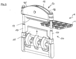
- the Figure 2 The punching beam 11 shown is accommodated in a frame 14.
- a punching lower tool 15 is also accommodated in the frame 14.
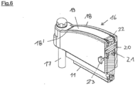
- FIGs 4 and 5 show that the shell element 19 is connected to the shell elements 18 and 18' via a pendulum joint 20.
- the shell element 19 can swing within the two outer shell elements 18, 18', as shown by the double arrow 25 in Figure 5
- the shell element 19 carries the punching beam 11.
- Figures 4 and 6 show that the pendulum joint 20 has an eccentric section, which allows a change in the height of the shell element 19 relative to the shell elements 18, 18'.
- On the A disk 21 is arranged in the eccentric section of the pendulum joint 20. This is accommodated in the middle shell element 19. Height adjustments can be made via knurled sections 22, a fixing element 23 corresponds to a row of holes 24. The rotational position of the pendulum joint 20 can be determined using the fixing element 23.
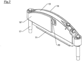
- FIGs 7 and 8 show an alternative embodiment of the shell element 19.
- the shell element 19 is again connected to the shell elements 18 and 18' via the pendulum joint 20, but an alternative mechanism for changing the height of the shell element 19 is designed.
- This alternative mechanism comprises a wedge-shaped frame 26a, which is arranged obliquely to the horizontal.
- the frame 26a is assigned a spindle drive 27, which is attached to the frame 26a.
- Figure 8 directly shows the shell element 19.
- Figure 9 shows that the spindle drive 27 is guided outwards within the shell element 19 to a handle 28.
- a further handle 29 is also provided, which serves to clamp the spindle drive 27.
- Figure 8 shows that the wedge-shaped frame 26a has its wedge shape within a frame cutout, i.e. on the inside of the frame 26a. Moving this frame 26a causes a change in the height of the arrangement of the shell element 19.
Landscapes
- Engineering & Computer Science (AREA)
- Mechanical Engineering (AREA)
- Life Sciences & Earth Sciences (AREA)
- Forests & Forestry (AREA)
- Perforating, Stamping-Out Or Severing By Means Other Than Cutting (AREA)
- Auxiliary Devices For And Details Of Packaging Control (AREA)
Applications Claiming Priority (1)
| Application Number | Priority Date | Filing Date | Title |
|---|---|---|---|
| DE102022125320.1A DE102022125320A1 (de) | 2022-09-30 | 2022-09-30 | Vorrichtung zum Trennen zumindest eines insbesondere geförderten Flächenelementes, insbesondere einer Kunststofffolie oder eines Kunststofffolienverbundmaterials in einzelne Bestandteile |
Publications (3)
| Publication Number | Publication Date |
|---|---|
| EP4344840A1 EP4344840A1 (de) | 2024-04-03 |
| EP4344840C0 EP4344840C0 (de) | 2025-03-05 |
| EP4344840B1 true EP4344840B1 (de) | 2025-03-05 |
Family
ID=88197191
Family Applications (1)
| Application Number | Title | Priority Date | Filing Date |
|---|---|---|---|
| EP23199435.1A Active EP4344840B1 (de) | 2022-09-30 | 2023-09-25 | Vorrichtung zum trennen eines flächenelementes, insbesondere einer kunststofffolie in einzelne bestandteile |
Country Status (7)
| Country | Link |
|---|---|
| US (1) | US20240109220A1 (pl) |
| EP (1) | EP4344840B1 (pl) |
| JP (1) | JP2024052645A (pl) |
| DE (1) | DE102022125320A1 (pl) |
| ES (1) | ES3032012T3 (pl) |
| HU (1) | HUE071779T2 (pl) |
| PL (1) | PL4344840T3 (pl) |
Family Cites Families (8)
| Publication number | Priority date | Publication date | Assignee | Title |
|---|---|---|---|---|
| US3763690A (en) * | 1972-04-17 | 1973-10-09 | Dreis & Krump Manuf Co | Press brake ram leveling |
| CH652967A5 (fr) * | 1982-04-15 | 1985-12-13 | Bobst Sa | Presse a platines. |
| GB8513956D0 (en) * | 1985-06-03 | 1985-07-03 | Samco Strong Ltd | Cutting press |
| DE59812614D1 (de) * | 1998-04-30 | 2005-04-07 | Bruderer Ag Frasnacht Arbon | Stanzpresse, insbesondere Schnelläuferpresse |
| CN102581866B (zh) * | 2012-01-18 | 2015-07-15 | 杭州惠宝机电有限公司 | 切书器滑槽式双向斜切装置 |
| ES2643117T3 (es) * | 2013-02-20 | 2017-11-21 | Multivac Sepp Haggenmüller Gmbh & Co. Kg | Máquina de envasado por embutición profunda con equipo de elevación y procedimiento |
| DE102015211622A1 (de) * | 2015-06-23 | 2016-12-29 | Multivac Sepp Haggenmüller Se & Co. Kg | Tiefziehverpackungsmaschine mit Folienstanze |
| US11298848B1 (en) * | 2019-01-22 | 2022-04-12 | Core Stripper, Inc. | Bulk roll cutting apparatus with safety linkage and related methods |
-
2022
- 2022-09-30 DE DE102022125320.1A patent/DE102022125320A1/de active Pending
-
2023
- 2023-09-25 EP EP23199435.1A patent/EP4344840B1/de active Active
- 2023-09-25 PL PL23199435.1T patent/PL4344840T3/pl unknown
- 2023-09-25 HU HUE23199435A patent/HUE071779T2/hu unknown
- 2023-09-25 ES ES23199435T patent/ES3032012T3/es active Active
- 2023-09-29 US US18/478,764 patent/US20240109220A1/en active Pending
- 2023-09-29 JP JP2023170547A patent/JP2024052645A/ja active Pending
Also Published As
| Publication number | Publication date |
|---|---|
| EP4344840A1 (de) | 2024-04-03 |
| JP2024052645A (ja) | 2024-04-11 |
| HUE071779T2 (hu) | 2025-09-28 |
| DE102022125320A1 (de) | 2024-04-04 |
| PL4344840T3 (pl) | 2025-10-20 |
| US20240109220A1 (en) | 2024-04-04 |
| EP4344840C0 (de) | 2025-03-05 |
| ES3032012T3 (en) | 2025-07-14 |
Similar Documents
| Publication | Publication Date | Title |
|---|---|---|
| DE2622393C3 (de) | Vorrichtung zum Verpacken von Gegenständen | |
| EP3718715B1 (de) | Längsschneidung mit integrierter förderrolle | |
| DE1074392B (de) | Querschneider für Papier- oder dergleichen bahnen | |
| WO2012055633A1 (de) | Vorrichtung zum trennen eines packstoffs für eine verpackung | |
| DE19516953B4 (de) | Vorrichtung zum Seitenschneiden von Papier | |
| WO2022078789A1 (de) | Verpackungsmaschine sowie verfahren zur verpackung einer behältnisgruppe aus mehreren behältnissen | |
| EP0111210B1 (de) | Vorrichtung zum Umhüllen von Gegenständen mit einer Folie aus Kunststoff oder dergl. | |
| CH632965A5 (de) | Vorrichtung zum herstellen und fuellen von verpackungsmitteln fuer waren und gegenstaende. | |
| CH388087A (de) | Verfahren zum Sieken und/oder Schlitzen von Karton und dergleichen und Maschine zur Durchführung des Verfahrens | |
| DE3505858C2 (pl) | ||
| DE2342556C3 (de) | Vorrichtung zum Fräsen von Mauerblöcken | |
| EP2396227B1 (de) | Schneid- und spreizvorrichtung | |
| EP4344840B1 (de) | Vorrichtung zum trennen eines flächenelementes, insbesondere einer kunststofffolie in einzelne bestandteile | |
| DE102007008258A1 (de) | Nickbreaker | |
| EP2295320A2 (de) | Vorrichtung und Verfahren zum Handhaben von Stapeln aus Druckträgern | |
| DE10109111C1 (de) | Stanzstation zum Austrennen von Teilen aus thermoplastischem Kunststoff | |
| EP0293574B1 (de) | Bandschleifmaschine | |
| EP2246261B1 (de) | Vorrichtung und Verfahren zum Egalisieren von mit Schüttgut oder pastösem Gut befüllten Verpackungen | |
| DE102009008936A1 (de) | Schneid- und Spreizvorrichtung | |
| EP0410226B1 (de) | Vorrichtung zum klebstofffreien Verbinden von Lagen aus Papier, dünnem Karton od. dgl. | |
| DE3020633A1 (de) | Verpackungsmaschine mit einem ausschneidwerkzeug | |
| DE2632425C3 (de) | Maschine zum öffnen von Briefumschlägen | |
| DE10260064A1 (de) | Querschneideeinrichtung mit Scherenschnittprinzip | |
| DE2315430C3 (de) | Vorrichtung zum gleichzeitigen Zuführen von zwei dicht nebeneinanderliegenden Verpackungszuschnitten | |
| EP4275850A1 (de) | Vorrichtung zum stanzen eines geförderten flächenelementes |
Legal Events
| Date | Code | Title | Description |
|---|---|---|---|
| PUAI | Public reference made under article 153(3) epc to a published international application that has entered the european phase |
Free format text: ORIGINAL CODE: 0009012 |
|
| STAA | Information on the status of an ep patent application or granted ep patent |
Free format text: STATUS: THE APPLICATION HAS BEEN PUBLISHED |
|
| AK | Designated contracting states |
Kind code of ref document: A1 Designated state(s): AL AT BE BG CH CY CZ DE DK EE ES FI FR GB GR HR HU IE IS IT LI LT LU LV MC ME MK MT NL NO PL PT RO RS SE SI SK SM TR |
|
| STAA | Information on the status of an ep patent application or granted ep patent |
Free format text: STATUS: REQUEST FOR EXAMINATION WAS MADE |
|
| 17P | Request for examination filed |
Effective date: 20240610 |
|
| RBV | Designated contracting states (corrected) |
Designated state(s): AL AT BE BG CH CY CZ DE DK EE ES FI FR GB GR HR HU IE IS IT LI LT LU LV MC ME MK MT NL NO PL PT RO RS SE SI SK SM TR |
|
| GRAP | Despatch of communication of intention to grant a patent |
Free format text: ORIGINAL CODE: EPIDOSNIGR1 |
|
| STAA | Information on the status of an ep patent application or granted ep patent |
Free format text: STATUS: GRANT OF PATENT IS INTENDED |
|
| INTG | Intention to grant announced |
Effective date: 20241119 |
|
| GRAS | Grant fee paid |
Free format text: ORIGINAL CODE: EPIDOSNIGR3 |
|
| GRAA | (expected) grant |
Free format text: ORIGINAL CODE: 0009210 |
|
| STAA | Information on the status of an ep patent application or granted ep patent |
Free format text: STATUS: THE PATENT HAS BEEN GRANTED |
|
| AK | Designated contracting states |
Kind code of ref document: B1 Designated state(s): AL AT BE BG CH CY CZ DE DK EE ES FI FR GB GR HR HU IE IS IT LI LT LU LV MC ME MK MT NL NO PL PT RO RS SE SI SK SM TR |
|
| REG | Reference to a national code |
Ref country code: GB Ref legal event code: FG4D Free format text: NOT ENGLISH |
|
| REG | Reference to a national code |
Ref country code: CH Ref legal event code: EP |
|
| REG | Reference to a national code |
Ref country code: DE Ref legal event code: R096 Ref document number: 502023000652 Country of ref document: DE |
|
| REG | Reference to a national code |
Ref country code: IE Ref legal event code: FG4D Free format text: LANGUAGE OF EP DOCUMENT: GERMAN |
|
| U01 | Request for unitary effect filed |
Effective date: 20250403 |
|
| U07 | Unitary effect registered |
Designated state(s): AT BE BG DE DK EE FI FR IT LT LU LV MT NL PT RO SE SI Effective date: 20250410 |
|
| PG25 | Lapsed in a contracting state [announced via postgrant information from national office to epo] |
Ref country code: RS Free format text: LAPSE BECAUSE OF FAILURE TO SUBMIT A TRANSLATION OF THE DESCRIPTION OR TO PAY THE FEE WITHIN THE PRESCRIBED TIME-LIMIT Effective date: 20250605 |
|
| REG | Reference to a national code |
Ref country code: ES Ref legal event code: FG2A Ref document number: 3032012 Country of ref document: ES Kind code of ref document: T3 Effective date: 20250714 |
|
| PG25 | Lapsed in a contracting state [announced via postgrant information from national office to epo] |
Ref country code: HR Free format text: LAPSE BECAUSE OF FAILURE TO SUBMIT A TRANSLATION OF THE DESCRIPTION OR TO PAY THE FEE WITHIN THE PRESCRIBED TIME-LIMIT Effective date: 20250305 |
|
| PG25 | Lapsed in a contracting state [announced via postgrant information from national office to epo] |
Ref country code: GR Free format text: LAPSE BECAUSE OF FAILURE TO SUBMIT A TRANSLATION OF THE DESCRIPTION OR TO PAY THE FEE WITHIN THE PRESCRIBED TIME-LIMIT Effective date: 20250606 |
|
| REG | Reference to a national code |
Ref country code: HU Ref legal event code: AG4A Ref document number: E071779 Country of ref document: HU |
|
| PG25 | Lapsed in a contracting state [announced via postgrant information from national office to epo] |
Ref country code: SM Free format text: LAPSE BECAUSE OF FAILURE TO SUBMIT A TRANSLATION OF THE DESCRIPTION OR TO PAY THE FEE WITHIN THE PRESCRIBED TIME-LIMIT Effective date: 20250305 |
|
| U20 | Renewal fee for the european patent with unitary effect paid |
Year of fee payment: 3 Effective date: 20250903 |
|
| PGFP | Annual fee paid to national office [announced via postgrant information from national office to epo] |
Ref country code: NO Payment date: 20250919 Year of fee payment: 3 |
|
| PGFP | Annual fee paid to national office [announced via postgrant information from national office to epo] |
Ref country code: TR Payment date: 20250917 Year of fee payment: 3 |
|
| PGFP | Annual fee paid to national office [announced via postgrant information from national office to epo] |
Ref country code: HU Payment date: 20250917 Year of fee payment: 3 |
|
| PG25 | Lapsed in a contracting state [announced via postgrant information from national office to epo] |
Ref country code: CZ Free format text: LAPSE BECAUSE OF FAILURE TO SUBMIT A TRANSLATION OF THE DESCRIPTION OR TO PAY THE FEE WITHIN THE PRESCRIBED TIME-LIMIT Effective date: 20250305 |
|
| PGFP | Annual fee paid to national office [announced via postgrant information from national office to epo] |
Ref country code: IE Payment date: 20250919 Year of fee payment: 3 |
|
| PG25 | Lapsed in a contracting state [announced via postgrant information from national office to epo] |
Ref country code: SK Free format text: LAPSE BECAUSE OF FAILURE TO SUBMIT A TRANSLATION OF THE DESCRIPTION OR TO PAY THE FEE WITHIN THE PRESCRIBED TIME-LIMIT Effective date: 20250305 |
|
| PG25 | Lapsed in a contracting state [announced via postgrant information from national office to epo] |
Ref country code: IS Free format text: LAPSE BECAUSE OF FAILURE TO SUBMIT A TRANSLATION OF THE DESCRIPTION OR TO PAY THE FEE WITHIN THE PRESCRIBED TIME-LIMIT Effective date: 20250705 |
|
| PLBE | No opposition filed within time limit |
Free format text: ORIGINAL CODE: 0009261 |
|
| STAA | Information on the status of an ep patent application or granted ep patent |
Free format text: STATUS: NO OPPOSITION FILED WITHIN TIME LIMIT |
|
| REG | Reference to a national code |
Ref country code: CH Ref legal event code: L10 Free format text: ST27 STATUS EVENT CODE: U-0-0-L10-L00 (AS PROVIDED BY THE NATIONAL OFFICE) Effective date: 20260114 |
|
| PGFP | Annual fee paid to national office [announced via postgrant information from national office to epo] |
Ref country code: PL Payment date: 20250912 Year of fee payment: 3 |
|
| PGFP | Annual fee paid to national office [announced via postgrant information from national office to epo] |
Ref country code: ES Payment date: 20251020 Year of fee payment: 3 |
|
| 26N | No opposition filed |
Effective date: 20251208 |