EP4344571B1 - Sohlenaufbau mit propriozeptiven elementen - Google Patents
Sohlenaufbau mit propriozeptiven elementen Download PDFInfo
- Publication number
- EP4344571B1 EP4344571B1 EP24156777.5A EP24156777A EP4344571B1 EP 4344571 B1 EP4344571 B1 EP 4344571B1 EP 24156777 A EP24156777 A EP 24156777A EP 4344571 B1 EP4344571 B1 EP 4344571B1
- Authority
- EP
- European Patent Office
- Prior art keywords
- holes
- midsole body
- proprioceptive
- proprioceptive elements
- footwear
- Prior art date
- Legal status (The legal status is an assumption and is not a legal conclusion. Google has not performed a legal analysis and makes no representation as to the accuracy of the status listed.)
- Active
Links
Images


Classifications
-
- A—HUMAN NECESSITIES
- A43—FOOTWEAR
- A43B—CHARACTERISTIC FEATURES OF FOOTWEAR; PARTS OF FOOTWEAR
- A43B13/00—Soles; Sole-and-heel integral units
- A43B13/14—Soles; Sole-and-heel integral units characterised by the constructive form
- A43B13/22—Soles made slip-preventing or wear-resisting, e.g. by impregnation or spreading a wear-resisting layer
- A43B13/223—Profiled soles
-
- A—HUMAN NECESSITIES
- A43—FOOTWEAR
- A43B—CHARACTERISTIC FEATURES OF FOOTWEAR; PARTS OF FOOTWEAR
- A43B13/00—Soles; Sole-and-heel integral units
- A43B13/02—Soles; Sole-and-heel integral units characterised by the material
- A43B13/12—Soles with several layers of different materials
-
- A—HUMAN NECESSITIES
- A43—FOOTWEAR
- A43B—CHARACTERISTIC FEATURES OF FOOTWEAR; PARTS OF FOOTWEAR
- A43B13/00—Soles; Sole-and-heel integral units
- A43B13/14—Soles; Sole-and-heel integral units characterised by the constructive form
- A43B13/141—Soles; Sole-and-heel integral units characterised by the constructive form with a part of the sole being flexible, e.g. permitting articulation or torsion
-
- A—HUMAN NECESSITIES
- A43—FOOTWEAR
- A43B—CHARACTERISTIC FEATURES OF FOOTWEAR; PARTS OF FOOTWEAR
- A43B13/00—Soles; Sole-and-heel integral units
- A43B13/14—Soles; Sole-and-heel integral units characterised by the constructive form
- A43B13/18—Resilient soles
- A43B13/187—Resiliency achieved by the features of the material, e.g. foam, non liquid materials
- A43B13/188—Differential cushioning regions
-
- A—HUMAN NECESSITIES
- A43—FOOTWEAR
- A43B—CHARACTERISTIC FEATURES OF FOOTWEAR; PARTS OF FOOTWEAR
- A43B13/00—Soles; Sole-and-heel integral units
- A43B13/14—Soles; Sole-and-heel integral units characterised by the constructive form
- A43B13/22—Soles made slip-preventing or wear-resisting, e.g. by impregnation or spreading a wear-resisting layer
- A43B13/223—Profiled soles
- A43B13/226—Profiled soles the profile being made in the foot facing surface
-
- A—HUMAN NECESSITIES
- A43—FOOTWEAR
- A43B—CHARACTERISTIC FEATURES OF FOOTWEAR; PARTS OF FOOTWEAR
- A43B13/00—Soles; Sole-and-heel integral units
- A43B13/02—Soles; Sole-and-heel integral units characterised by the material
- A43B13/12—Soles with several layers of different materials
- A43B13/125—Soles with several layers of different materials characterised by the midsole or middle layer
- A43B13/127—Soles with several layers of different materials characterised by the midsole or middle layer the midsole being multilayer
-
- A—HUMAN NECESSITIES
- A43—FOOTWEAR
- A43B—CHARACTERISTIC FEATURES OF FOOTWEAR; PARTS OF FOOTWEAR
- A43B13/00—Soles; Sole-and-heel integral units
- A43B13/14—Soles; Sole-and-heel integral units characterised by the constructive form
- A43B13/18—Resilient soles
- A43B13/187—Resiliency achieved by the features of the material, e.g. foam, non liquid materials
-
- A—HUMAN NECESSITIES
- A43—FOOTWEAR
- A43B—CHARACTERISTIC FEATURES OF FOOTWEAR; PARTS OF FOOTWEAR
- A43B7/00—Footwear with health or hygienic arrangements
- A43B7/14—Footwear with health or hygienic arrangements with foot-supporting parts
- A43B7/24—Insertions or other supports preventing the foot canting to one side , preventing supination or pronation
-
- B—PERFORMING OPERATIONS; TRANSPORTING
- B32—LAYERED PRODUCTS
- B32B—LAYERED PRODUCTS, i.e. PRODUCTS BUILT-UP OF STRATA OF FLAT OR NON-FLAT, e.g. CELLULAR OR HONEYCOMB, FORM
- B32B2437/00—Clothing
- B32B2437/02—Gloves, shoes
Definitions
- Footwear typically includes a sole structure configured to be located under a wearer's foot to space the foot away from the ground.
- Sole structures in athletic footwear are configured to provide one or more of desired cushioning, motion control, and resiliency.
- US 2009/282704 A1 describes an air circulating, shock absorbing shoes which reduce the impact exerted to the feet of the wearer by providing ventilation in the shoes, resulting in pleasant and comfortable wearing of shoes.
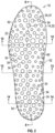
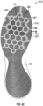
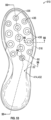
- FIG. 1 is a bottom view of a portion of a sole structure 10 for an article of footwear 12 shown in FIGS. 4 and 15 .
- FIG. 1 shows a midsole 14 of the sole structure 10.
- the midsole 14 includes a midsole body 32 with a plurality of holes 34 that open at the proximal surface 22.
- the midsole body 32 may be a polymeric foam material that provides cushioning and support.
- the holes 34 are through-holes that extend from the proximal surface 22 of the midsole body 32 to a distal surface 23 of the midsole body 32.
- the distal surface 23 is shown in the bottom view of FIG. 1 and is indicated in FIG. 6 .
- the midsole 14 also includes a plurality of proprioceptive elements 36 disposed in some of the holes 34 such that they are translatable in the holes 34 as described herein.
- the proprioceptive elements 36 are indicated with dot shading for clarity. Distal ends 38 of the proprioceptive elements 36 are shown.
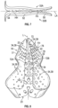
- FIG. 2 shows the midsole 14 prior to installation of the proprioceptive elements 36 in the holes 34.
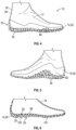
- a flexible outsole 16 shown in phantom in FIG. 4 and in cross-sectional view in FIG. 15
- an upper 18 shown in FIG. 4
- the sole structure 10 is one of many embodiments of sole structures disclosed herein that include proprioceptive elements that enhance a wearer's awareness of an object in contact with the article of footwear, and of the location of contact of the object on the article of footwear.
- a midsole with proprioceptive elements as discussed herein improves proprioceptive feedback (i.e., tactile feedback), which may enhance ball control in ball sports, such as soccer.
- the sole structures disclosed herein may also have enhanced ability to grip a ball, such as due to protrusions of distal ends of the proprioceptive elements at a distal surface of the outsole, and/or due to the ability of the outsole and midsole to flex together both during dorsiflexion and plantarflexion.
- Other features and advantages of the various embodiments of sole structures with proprioceptive elements are set forth in the discussion herein.
- the article of footwear 12 includes an upper 18 secured to the sole structure 10.
- the upper 18 is a sock construction, such as a bootie, and may be a unitary, 360-degree knit material that has a distal surface 20 secured to a proximal surface 22 of the sole structure 10 (best shown in FIG. 6 ).
- the upper 18 thus wraps under a foot 24 received in a foot-receiving cavity 17 of the upper 18, and includes an underfoot portion 26 (see FIGS. 6 and 15 ) in lieu of a strobel.
- the upper 18 may terminate at a lower periphery that is secured to a strobel, with the strobel secured to the sole structure 10 similar to upper 618 in FIG.
- both a strobel having holes aligned with the holes 34 in the midsole body 32, and a sockliner having holes aligned with the holes in the strobel may overlay the midsole 14.
- An upper layer of the sockliner may directly overlay the proprioceptive elements 36 between the foot 24 and the proprioceptive elements 36.
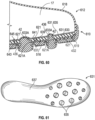
- FIG. 60 shows such an upper layer 635, which is a relatively thin, flexible, elastically-stretchable material, such as a four-way stretch fabric.
- the midsole body 32 has a thickness sufficient such that a sockliner is not used.
- the midsole body 32 could be placed between an inner sock and an outer sock, as described with respect to the midsole body 232 of FIGS. 37-39 .
- the connecting web can be secured at select locations to the proximal surface of the midsole (or, in some embodiments, to the distal surface of the midsole body) such that translation of the proprioceptive elements as described herein is not unduly limited.
- the web may be left disconnected from the midsole surface at regions around each of the proprioceptive elements.
- At least some of the proprioceptive elements 36 may have a different density than the midsole body 32 so that they are compressible relative to the midsole body 32 along their central axes.
- the midsole body 32 may have a first density
- the proprioceptive elements 36 may have a second density less than the first density.
- the second density may be greater than the first density.
- Some or all of the proprioceptive elements 36 may be more dense than the midsole body 32, or some or all may be less dense than the midsole body 32. Some or all could also have the same density as the midsole body 32.
- the proprioceptive elements 36 may be referred to as plugs, and are disposed in the holes 34 but spaced apart from the interior walls 44 of the midsole body 32 that define the holes. Accordingly, the proprioceptive elements 36 do not in fact plug the holes.
- the holes 34 are cylindrical in shape, and the proprioceptive elements 36 may also be cylindrical.
- the proprioceptive elements 36 are elongated, with a length greater than their width. Depending on the thickness of the midsole body 32, some of the holes 34 could have a width greater than their length, in which case the proprioceptive element 36 disposed in that hole 34 may be a cylinder that is discoid (i.e., has a width greater than its length).
- the midsole body 32 is shown as having holes 34 in each of a forefoot region 50, a midfoot region 52, and a heel region 54 of the midsole body 32.
- the holes 34 may be disposed in only one of or any two of the forefoot region 50, the midfoot region 52, and the heel region 54.
- Each hole 34 has a distal opening 37, also referred to as a distal end 37, at the distal surface 23 of the midsole body 32.
- the distal ends 37 of the holes 34 are the ends shown in the bottom view of FIG. 2 , for example.
- Each hole 34 also has a proximal opening 39, also referred to as a proximal end 39, at the proximal surface 22 of the midsole body 32 such that each hole 34 is a through-hole.
- FIG. 8 indicates the proximal ends 39 of the holes 34.
- the holes 34 are disposed in both of a bottom portion 60 ( FIG. 2 ), a medial sidewall portion 62 ( FIG. 5 ), and a lateral sidewall portion 64 ( FIG. 4 ) of the midsole body 32. In other embodiments, holes 34 may be provided only in the bottom portion 60, or only in one or both of the sidewall portions 62, 64.
- the holes 34 have a variety of different diameters.
- the midsole body 14 can provide greater cushioning at a hole 34 with a larger diameter than a hole 34 with a smaller diameter, due to the ability of the surrounding foam to collapse into the hole 34 under loading, assuming no proprioceptive element 36 is disposed in the hole 34.
- the collapse of the midsole body 32 into an empty hole 34 when under forces not aligned with the central axis CA of the hole 34 is indicated in FIG. 16 .
- Holes 34 in the midfoot region 52 are empty (i.e., they contain no proprioceptive elements 36).
- the holes 34 containing proprioceptive elements 36 in the forefoot region 50 may be referred to as a first set of holes, and the holes 34 containing proprioceptive elements 36 in the heel region 54 may be referred to as a second set of holes 34.
- the proprioceptive elements 36 in the forefoot region 50 of FIG. 1 may have a density greater than or less than the density of the midsole body 32.
- proprioceptive elements 36 are provided only in the forefoot region 50 and are a foam material that has a greater density than the material of the midsole body 32.
- Proprioceptive elements are also disposed in holes 34 in the heel region 54, and may be configured for impact cushioning as well as proprioception.
- the proprioceptive elements 36 in the heel region 54 may be silicone.
- a proprioceptive element 36 may completely fill a hole 34 and act as a plug.
- proprioceptive elements 36 used in the heel region 54 for cushioning could be such plugs.
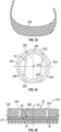
- the midsole body 32 may be polymeric foam that is compression-molded according to a thermal process, with the holes 34 formed during the molding process rather than via a secondary process. All outer surfaces of a molded foam article, such as a molded midsole body 32, may have an outer skin 66 that is denser than an interior portion 68 of the midsole body 32 due to contact with the surfaces of the mold tools.
- the outer skin 66 of the midsole body 32 is indicated in FIG. 16 , and is separated from the interior portion 68 by a representative boundary 70. Forming the holes 34 during molding via pins, as disclosed herein, will cause the interior walls 44 of the holes 34 to also have the dense outer skin 66.
- the midsole body 32 includes an interior portion 68, and a skin 66 that covers the interior portion 68 and extends along each of the holes 34 from the proximal surface 22 to the distal surface 23.
- the interior portion 68 may be an open-cell foam, or a closed-cell foam.
- air moves out of the cell when the foam is compressed. Accordingly, the compressive stiffness of the foam is unaffected by the air in the cells.
- a closed-cell foam air is trapped in the cell, and compresses when the foam is compressed, thus affecting the compressive stiffness of the foam.
- the skin 66 has a first density
- the interior portion 68 has a second density less than the first density.
- the cylinder of skin 66 around the hole 34 is most resistant to compression along its length, as the full length of the stiffer skin 66 must be compressed.
- the midsole body 32 thus has a greater compressive stiffness under loading along the center axis CA of a hole 34 than under loading transverse to the center axis CA, or than under loading at an oblique angle to the center axis CA (i.e., angles greater than zero degrees and less than 90 degrees).
- An empty hole 34, or a hole containing a proprioceptive element 36 of a lesser density than the midsole body 32 will provide cushioning and absorb forces that are not aligned with the center axis of a hole 34 by a partial or complete collapse of the foam midsole body 32 into the hole 34, as shown in FIG. 16 . Forces aligned with the center axis CA, however, will be at least partially countered by the resistance of the tunnel-like skin 66 at the hole 34, resisting compression.
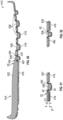
- the holes 34 are angled relative to a vertical axis V indicated in FIGS. 12 and 18 .
- the angle A of the central axis CA of a hole 34 relative to the vertical axis V may be selected so that the central axis CA aligns with an expected direction of loading force on the midsole body 32 at the location of the hole 34, such as the expected direction of impact forces during walking or running, or from making a lateral movement, such as a cutting movement during sports.
- lateral (i.e., sideways) cutting motions are common.
- Angles of holes 34 at the lateral sidewall 64 and/or the medial sidewall 62 may be selected to coincide with the lateral forces typically resulting from a lateral cutting motion.
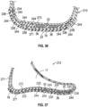
- the midsole body 32 is molded with a cleft 72 in the proximal surface 22 so that the midsole body 32 is in a "split open" position (referred to herein as a molded position), as shown in FIG. 8 .
- the cleft 72 extends along a longitudinal axis L of the midsole body 32.
- a mold could be configured to provide a cleft that extends transversely. With a longitudinally-extending cleft 72 as shown in FIG. 8 , when the cleft 72 is closed (as shown in FIG.
- the resulting angled holes angle laterally-outward from the proximal surface 22 to the distal surface 23.
- the central axes CA of the holes 34 extend vertically, and the center axes CA of the holes of the first set 76 are parallel with the center axes CA of the holes of the second set 78.
- a first set 76 of holes 34 is disposed between a medial periphery 77 of the midsole body 32 and the cleft 72
- a second set 78 of holes 34 is disposed between a lateral periphery 79 of the midsole body 32 and the cleft 72.
- the proximal openings 39 of the first set 76 are disposed at a first portion of the proximal surface 22, and the proximal openings 39 of the second set 78 are disposed at a second portion of the proximal surface 22.
- the first set 76 of holes 34 may be referred to as a medial set 76, and the second set 78 of holes 34 may be referred to as a lateral set 78.
- the midsole body 32 is hinged at the cleft 72.
- the cleft 72 extends downward from the proximal surface 22 only partway to the distal surface 23 at least in some regions, such that a first portion 32A (e.g., a medial portion) of the midsole body 32 with the medial set 76 of holes 34 is connected to a second portion 32B (e.g., a lateral portion) of the midsole body 32 at least at connected portions referred to as a forefoot hinge FH and a heel hinge HH at the bottom of the cleft 72.
- FIG. 7 is a schematic depiction of the midsole body 32 if pressed even further open at the cleft 72 than the molded position of FIG. 8 , so that the forefoot hinge FH and the heel hinge HH are apparent.
- the cleft 72 may extend completely through the midsole body 32 in some areas, such that the medial portion 32A and the lateral portion 32B may be completely split and disconnected from one another at an area rearward of the heel hinge HH, at an area forward of the forefoot hinge FH, and at an area between the forefoot hinge FH and the heel hinge HH, as shown in FIG. 7 .
- This allows the distal surface 23 to curve upward toward the foremost extent of the midsole body 32 at the forefoot portion 50 forward of the forefoot hinge FH, the distal surface 23 to curve upward toward the rearmost extent rearward of the heel hinge HH, and the distal surface 23 to curve upward at the midfoot portion 52 between the heel hinge HH and the forefoot hinge FH.
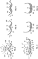
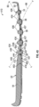
- FIGS. 9-11 show the midsole body 32 in the molded position with the cleft 72 open.
- the cleft 72 is shown as having an angle A between vertical V and each of its sidewalls 72A, 72B in the open (as molded) position.
- the sidewalls 72A, 72B are also indicated in FIG. 8 .
- the angle A may be, for example 40 degrees, so that a total opening between the sidewalls of the cleft 72 is 80 degrees. Accordingly, when the cleft 72 is closed, as shown in FIGS. 12-14 , the angled holes 34 will each extend laterally outward at angle A, which is 40 degrees in the embodiment shown.
- the angle of the holes 34 is best shown in the cross-sectional views of FIGS. 12, 13 , 15 and 18 .
- the center axes CA of the holes 34 of the first set 76 angle laterally outward from the proximal surface 22 to the distal surface 23 such that a distal end 37 of each hole 34 of the first set 76 is nearer to the medial periphery 77 than is a proximal end 39 of the hole 34.
- the center axes CA of the holes 34 of the second set 78 angle laterally outward from the proximal surface 22 to the distal surface 23 such that a distal end 37 of each hole 34 of the second set 78 is nearer to the lateral periphery 79 than is a proximal end 39 of the hole 34.
- the first portion 32A of the midsole body 32 is contiguous with the second portion 32B at the proximal surface 22 and at the distal surface 23 when the cleft 72 is closed.
- the cleft 72 may be kept in the closed position by thermally bonding or adhering the sidewalls 72A, 72B to one another.
- the bonding of an upper at the proximal surface 22 or an outsole at the distal surface 23 may serve to retain the cleft 72 in the closed position.
- the web 25 may be positioned over midsole body 32 with the cleft 72 in the open position, and the integral proprioceptive elements 36 may be inserted into the holes 34 effectively simultaneously simply by moving the connecting web 25 toward the proximal surface 22 with the proprioceptive elements 36 aligned with the holes 34.
- the web 25 may be stretchable such that it is pulled transversely to stretch across the cleft 72 during insertion, and retracts to a narrower width corresponding to the narrower width at the proximal surface 22 of the midsole body 32 with the cleft 72 in the closed position.
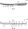
- the proximal surface 22A of the midsole body 32C is shown with internal flex grooves 84.
- the internal flex grooves 84 overlie and are aligned with the external flex grooves 82. More specifically, internal flex grooves 84 are arranged in a pattern matching the pattern of the external flex grooves 82 so that the internal flex grooves 84 border either side of centerlines of the external flex grooves 82, as best indicated in FIG. 22 .
- two internal flex grooves 84 extend parallel to one another, tracking the grooves 82 from above, with a narrow portion of the midsole body 32C between each of the internal flex grooves 84 directly overlying the external flex grooves 82.
- the internal flex grooves 84 and the external flex grooves 82 allow the midsole body 32C and outsole 16A to function as pleated bellows at the grooves 82, 84 such that the sole structure 10A articulates at the external flex grooves 82 and the internal flex grooves 84 both in dorsiflexion (e.g., along curve 85) and in plantarflexion (e.g., along curve 86) of the sole structure 10A, as best depicted in FIG. 22 .
- Curve 85 represents a degree of articulation at which at least some of the internal flex grooves 84 will close.
- Curve 86 represents a degree of plantar flexion at which at least some of the external flex grooves 82 will close.
- the longitudinally-extending flex grooves 82, 84 allow articulation in the transverse direction of the sole structure 10A as well, such as during plantarflexion over a curved ball surface.
- FIGS. 23-24 show a representative mold 90 for manufacturing the midsole body 32.
- FIG. 25 is a flowchart of a method of manufacturing the midsole body 32 using the mold 90 of FIGS. 23-24 .
- the mold 90 includes an upper mold half 90A and a lower mold half 90B.
- the upper mold half 90A has an upper mold surface 91A in a mold cavity 92
- the lower mold half 90B has a lower mold surface 91B in the mold cavity 92.
- the mold halves 90A, 90B are movable toward one another to the closed position shown in FIGS. 23 and 24 , in which the mold surfaces 91A, 91B together form a mold cavity 92.
- the mold halves 90A, 90B are movable away from one another to open the mold cavity 92 (e.g., by moving mold half 90A upward in FIG. 23 , moving mold half 90B downward, or both, as will be understood from the present disclosure to those skilled in the art.
- the upper mold surface 91A includes a protrusion 93 that extends toward the lower mold half 90B.
- the lower mold half 90B also includes a protrusion 94. Both protrusions 93, 94 run along a longitudinal axis of the mold 90, which is perpendicular to the plane of the cross-section shown.
- the protrusion 93 forms the cleft 72 shown in the midsole body 32 in FIG.
- the protrusion 94 molds the distal surface 23 of the midsole body 32 to the open position.
- the protrusions 93, 94 may touch. Such regions will correspond to the areas where the cleft 72 extends completely through the midsole body 32, where the medial portion 32A and the lateral portion 32B are completely split and disconnected from one another (e.g., at an area rearward of the heel hinge HH, at an area forward of the forefoot hinge FH, and at an area between the forefoot hinge FH and the heel hinge HH, as described with respect to FIG. 7 ).
- the upper mold half 90A has through-holes 95A
- the lower mold half 90B has blind holes 95B.
- through-holes 95A may be used in lieu of blind holes 95B.
- the through-holes and blind holes 95A, 95B are aligned with one another to receive a first set of pins 96A, and a second set of pins 96B, as shown in FIG. 24 .
- the pins 96A, 96B extend from a mold tool 97 that is translatable toward and away from the mold 90. A single mold tool 97 is used.
- the first and second sets of pins 96A, 96B may be secured to separate mold tools.
- the pins 96A, 96B and the holes 95A, 95B are arranged in the same pattern (i.e., relative spacing and size), which is identical to the pattern of the holes 34 in the midsole body 32.
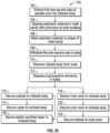
- FIG. 25 is a flowchart illustrating a method 100 of manufacturing an article of footwear, such as the article of footwear 12.
- the method 100 includes extending a first set of pins 96A into the midsole cavity 92 on a first side of the protrusion 94 (i.e., on the medial side), and a second set of pins 96B into the midsole cavity 92 on a second side of the protrusion 94 (i.e., on the lateral side).
- the first set of pins 96A forms the first set 76 of holes 34 in the midsole body 32
- the second set of pins 96B forms the second set 78 of holes 34 in the midsole body 32
- the protrusion 93 forms the cleft 72 between the first set 76 of holes and the second set 78 of holes, all shown in FIG. 8 .
- Center axes CP1 of the pins of the first set of pins 96A are parallel with center axes CP2 of pins of the second set 96B.
- the method 100 includes block 104, disposing polymeric material 98 into a mold cavity 92 of a mold 90 for a midsole body 32.
- the polymeric material 98 may be introduced through an injection port 99 of the mold 90.
- the method 100 continues with block 106, molding the polymeric material to the shape of the mold surface, thereby forming a midsole body 32.
- Molding in block 106 may include compression, vacuum-forming, and/or thermal processing.
- blocks 102, 104, and 106 can be performed in a different order than as described.
- the method 100 includes withdrawing the first set of pins 96A and the second set of pins 96B from the midsole body 32. Because the pins 96A, 96B are parallel, the same mold tool 97 can be used to form the first and second sets 76, 78 of holes 34 simultaneously. Additionally, because the holes 34 are formed during molding, rather than during a secondary process following molding, the skin 66 borders the less dense, interior portion 68 of the midsole body 32, providing compression resistance to forces along the central axes of the holes 34, as discussed with respect to FIG. 15 .
- the method 100 includes removing the midsole body 32 from the mold 90.
- center axes CA of the holes 34 of the first set 76 of holes are nonparallel with center axes CA of the holes 34 of the second set 78 of holes when the cleft 72 is closed.
- the method 100 may include disposing a first plurality of proprioceptive elements 36 in at least some holes 34 of the first set 76 and a second plurality of proprioceptive elements 36 in at least some holes 34 of the second set 78.
- this may including placing the connecting web 25 above the midsole body 32, and aligning the proprioceptive elements 36 with the holes 34.
- block 112 will include placing the layer above (e.g., if the layer is a sockliner) or below (e.g., if the layer is an outsole) the midsole body 32, and aligning the proprioceptive elements 36 with the holes 34.
- block 112 will include separately aligning and disposing each proprioceptive element 36 into a respective hole 34 of the correct size.
- a first set of proprioceptive elements 36 are disposed in the forefoot region 50, and a second set of proprioceptive elements 36 are disposed in the heel region 54.
- the first plurality of proprioceptive elements may have a first density
- the second plurality of proprioceptive elements may have a second density different than the first density.
- the midsole body 32 may have a density at the skin 66, and a different density at the interior portion 68, both of which are different than the densities of the proprioceptive elements 36.
- the proprioceptive elements 36 of the first set 76 may be a polymeric foam that has a density greater than or lesser than the midsole body 32.
- the proprioceptive elements 36 of the second set 78 may be silicone.
- the method 100 may include block 113, securing an outsole, such as outsole 16 or 16A described herein, to the distal surface 23 of the midsole body 32. In some embodiments, securing an outsole may occur later in the method 100, such as after block 118 described herein. If block 113 is performed following block 112, then the method 100 moves to either of blocks 114 or 116.
- Block 114 includes securing an upper 18, such as a sock, to the proximal surface 22 of the midsole body 32.
- the method 100 includes block 116, securing an elastic sockliner layer to the proximal surface 22 of the midsole body 32.
- the elastic sockliner layer may be, for example, elastic sockliner layer 635 as described with respect to FIGS. 59-61 , with the elastic sockliner layer spanning across the first set 76 of holes 34 and the second set 78 of holes 34.
- a sockliner is not required, however, as the midsole body 32 has a thickness sufficient to also serve as a sockliner.
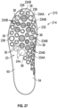
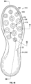
- FIG. 26 shows another embodiment of a sole structure 210A having a midsole 214A for an article of footwear 212.
- the sole structure 210A includes a midsole 214A with a midsole body 232.
- the midsole 214A may be used in the article of footwear 212 shown in FIGS. 37-39 in lieu of midsole 214.
- the midsole body 232 has perforations 244 that extend from the proximal surface 22 to the distal surface 23.
- the distal surface 23 is shown, but it is apparent that the perforations 244 extend entirely through the thickness of the midsole body 232 from the proximal surface 22 to the distal surface 23.
- the perforations 244 define perforated shapes that are circular.
- the perforated shapes are integral portions 236 of the midsole body 232 and are surrounded by three equally-spaced perforations 244.
- the integral portions 236 serve as proprioceptive elements 236.
- the three equally-spaced perforations 244 define a perforated hole 234A. As best shown in FIG.
- some or all of the integral proprioceptive elements 236 are punched out.
- multiple ones of the perforated shapes i.e., the integral proprioceptive elements 236) are punched out at the perforations 244 such that a plurality of punched through-holes 234B extend from the proximal surface 22 to the distal surface 23.
- the midsole body 232 with punched-out holes 234B is referred to as midsole 214 and is included in sole structure 210 of FIGS. 37-39 .
- an outsole 16 is removed for clarity in viewing the midsole 214.
- the midsole 214 may include a combination of: (i) integral proprioceptive elements 236 in perforated holes 234A formed during molding, three-dimensional printing, or otherwise forming of the midsole 214 or perforated therein during a secondary process; (ii) proprioceptive elements 36 disposed in punched through-holes 234B in a secondary process; and (iii) empty, punched through-holes 234B.
- the perforated holes 234A are disposed in a bottom portion 60, and in a medial sidewall portion 62 of the midsole body 232, in the forefoot region 50, and the midfoot region 52.
- the heel region 54 and the lateral sidewall portion 64 in the embodiment shown in FIGS. 26-29 generally have no perforated holes 234A of other holes, but in other embodiments, perforated holes 234A could be disposed in one or both of these portions as well.
- the inner sock 273 may be secured first by placing the inner sock 273 on a last, and then securing the midsole 214, including the midsole body 232 and the proprioceptive elements 236 to the inner sock 273.
- the outer sock 271 is then pulled over the inner sock 273 and midsole 214, and the proximal surface of the outer sock 271 is secured to the distal surface 23.
- the midsole body 232 is disposed inside of the outer sock 271, and between the inner sock 273 and the outer sock 271.
- the outsole 16A of FIG. 19 could be used with the midsole body 232, and the midsole body 232 could have internal flex grooves 84 at the proximal surface 22 (similarly as described with respect to midsole body 32C of FIG. 20 ) to enhance articulation of the sole structure 210 both in dorsiflexion and plantarflexion.
- FIG. 40 is a flowchart of a method 310 of manufacturing an article of footwear, such as article of footwear 212 and may apply to sole structure 210, 210A.
- the method 310 begins with block 312, perforating a midsole body 232 such that perforations 244 define a plurality of perforated shapes and extend through the midsole body 232 from a proximal surface 22 to a distal surface 23, creating perforated holes 234A.
- Perforating the midsole body 232 may be done during molding of the midsole body 232, in which case block 312 is a molding process.
- the midsole body 232 may be 3D printed, with the perforations created during the printing process by controlled material deposition.
- perforating the midsole body 232 may be a secondary process, in which case a molding process occurs prior to block 312.
- block 316 includes disposing proprioceptive elements 36 in one or more of the punched through-holes 234B, each proprioceptive element 36 disposed in a different one of the punched through-holes.
- the proprioceptive elements 36 may have a density different than a density of the midsole body 232.
- blocks 314 and 316 are omitted, so that the midsole body 232 includes only the perforated openings 234A, and the integral proprioceptive elements 236 are the only proprioceptive elements in the midsole body 232.
- block 314 occurs, but block 316 is omitted, so that all of the punched through-holes 234B remain empty.
- the method 310 proceeds to block 320, securing an outer sock 271 to the distal surface 23 of the midsole body 232 such that the midsole body 232 is disposed inside of the outer sock 271, and between the inner sock 273 and the outer sock 271.
- FIGS. 41-47 show another embodiment of a sole structure 410 for an article of footwear.
- the sole structure 410 includes a midsole 414 with a midsole body 432 and proprioceptive elements 436.
- the sole structure 410, midsole 414, midsole body 432, and proprioceptive elements 436 have many of the same features as described with respect to sole structure 10 and corresponding components thereof, and such features are referred to with like reference numbers and are as described with respect to sole structure 10.
- Block 717 securing an upper to a strobel
- block 718 securing the strobel to the proximal surface of the midsole body.
- Blocks 717 and 718 may be carried out, for example with upper 618, strobel 621, and midsole body 432 as described with respect to FIGS. 59-60 .
- the strobel 621 has through-holes 621A that align with the plurality of proprioceptive elements 436.
- block 718 includes block 720, aligning the through-holes 621A of the strobel 621 with the proprioceptive elements 436.
Landscapes
- Chemical & Material Sciences (AREA)
- Engineering & Computer Science (AREA)
- Materials Engineering (AREA)
- Health & Medical Sciences (AREA)
- Epidemiology (AREA)
- General Health & Medical Sciences (AREA)
- Public Health (AREA)
- Footwear And Its Accessory, Manufacturing Method And Apparatuses (AREA)
Claims (14)
- Schuhwerkartikel (12), umfassend:
eine Sohlenstruktur (10, 10A, 10B), umfassend:einen Zwischensohlenkörper (14, 32) mit einer proximalen Fläche bzw. Oberfläche (22) und einer distalen Fläche bzw. Oberfläche (23);wobei der Zwischensohlenkörper (14, 32) einen ersten Satz von Löchern (34), der sich durch den Zwischensohlenkörper (14, 32) von der proximalen Oberfläche (22) zu der distalen Oberfläche (23) erstreckt, einen zweiten Satz von Löchern (34), der sich durch den Zwischensohlenkörper (14, 32) von der proximalen Oberfläche (22) zu der distalen Oberfläche (23) erstreckt, und einen Spalt (72) aufweist, der sich teilweise durch den Zwischensohlenkörper (14, 32) zwischen dem ersten Satz von Löchern (34) und dem zweiten Satz von Löchern (34) erstreckt;wobei Mittelachsen (CA) der Löcher (34) des ersten Satzes parallel zu Mittelachsen (CA) der Löcher (34) des zweiten Satzes sind, wobei bzw. wenn der Spalt (72) offen ist, und nicht parallel zu den Mittelachsen (CA) der Löcher (34) des zweiten Satzes sind, wobei bzw. wenn der Spalt (72) geschlossen ist;eine Mehrzahl von propriozeptiven Elementen (36), wobei jedes propriozeptive Element (36) in einem unterschiedlichen Loch (34) des ersten oder des zweiten Satzes angeordnet ist und relativ zu dem Zwischensohlenkörper (14, 32) entlang einer Mittelachse (CA) des jeweiligen Lochs (34) in eine Richtung zu der proximalen Oberfläche (22) unter einer Kraft entlang der Mittelachse (CA) an einem distalen Ende (38) des propriozeptiven Elements (36) verschiebbar ist;einen Verbindungssteg (25), der mit der Mehrzahl von propriozeptiven Elementen (36) an entweder proximalen (39) oder distalen Enden (38) der Mehrzahl von propriozeptiven Elementen (36) derart integral ist, dass der Verbindungssteg (25) und die Mehrzahl von propriozeptiven Elementen (36) eine einzelne, unitäre bzw. einheitliche Komponente sind; undin Kombination mit einer Socke, die über dem Verbindungssteg (25) liegt, so dass sich die proximalen Enden (39) der Mehrzahl von propriozeptiven Elementen (36) in einen Fußaufnahmehohlraum (17) der Socke verschieben. - Schuhwerkartikel (12) nach Anspruch 1, wobei sich der Spalt (72) in der proximalen Oberfläche (22) befindet und sich entlang einer Längsachse (L) des Zwischensohlenkörpers (14, 32) erstreckt.
- Schuhwerkartikel (12) nach Anspruch 1, wobei:der erste Satz von Löchern (34) zwischen einem medialen Umfang bzw. Rand (77) des Zwischensohlenkörpers (14, 32) und dem Spalt (72) angeordnet ist; undder zweite Satz von Löchern (34) zwischen einem lateralen Umfang bzw. Rand (79) des Zwischensohlenkörpers (14, 32) und dem Spalt (72) angeordnet ist.
- Schuhwerkartikel (12) nach Anspruch 3, wobei:die Mittelachsen (CA) der Löcher (34) des ersten Satzes lateral nach außen von der proximalen Oberfläche (22) des Zwischensohlenkörpers (14, 32) zu der distalen Oberfläche (23) des Zwischensohlenkörpers (14, 32) abgewinkelt sind, so dass ein distales Ende (38) jedes Lochs (34) des ersten Satzes näher an dem medialen Rand (77) ist als ein proximales Ende (39) des Lochs (34); unddie Mittelachsen (CA) der Löcher (34) des zweiten Satzes lateral nach außen von der proximalen Oberfläche (22) des Zwischensohlenkörpers (14, 32) zu der distalen Oberfläche (23) des Zwischensohlenkörpers (14, 32) abgewinkelt sind, so dass ein distales Ende (38) jedes Lochs (34) des zweiten Satzes näher an dem lateralen Rand (79) ist als ein proximales Ende (39) des Lochs (34).
- Schuhwerkartikel (12) nach Anspruch 1, wobei:der Zwischensohlenkörper (14, 32) ein Polymerschaum ist und einen Innenabschnitt (68) sowie eine Haut enthält, die den Innenabschnitt (68) bedeckt und sich entlang jedes Lochs (34) des ersten Satzes und jedes Lochs (34) des zweiten Satzes von der proximalen Oberfläche (22) zu der distalen Oberfläche (23) erstreckt;die Haut eine erste Dichte aufweist; undder Innenabschnitt (68) eine zweite Dichte aufweist, die geringer ist als die erste Dichte, so dass der Zwischensohlenkörper (14, 32) eine größere Drucksteifigkeit unter einer Kraft des Zwischensohlenkörpers (14, 32) entlang der Mittelachse jedes Lochs (34) aufweist als quer zu der Mittelachse oder in einem schrägen Winkel zu der Mittelachse.
- Schuhwerkartikel (12) nach Anspruch 5, wobei der Innenabschnitt (68) ein offenzelliger Polymerschaum ist.
- Schuhwerkartikel (12) nach Anspruch 5, wobei der Innenabschnitt (68) ein geschlossenzelliger Polymerschaum ist.
- Schuhwerkartikel (12) nach Anspruch 1, wobei der Verbindungssteg (25) integral mit der Mehrzahl von propriozeptiven Elementen (36) an proximalen Enden (39) der Mehrzahl von propriozeptiven Elementen (36) ist, wobei der Verbindungssteg (25) konfiguriert ist, sich mit einem bzw. jedem der Mehrzahl von propriozeptiven Elementen (36), die sich relativ zu dem Zwischensohlenkörper (14, 32) in einer Richtung zu der proximalen Oberfläche (22) hin verschieben, von dem Zwischensohlenkörper (14, 32) abzuheben.
- Schuhwerkartikel (12) nach Anspruch 1, ferner umfassend:
eine Außen- bzw. Laufsohle (16) integral mit der Mehrzahl von propriozeptiven Elementen (36) an distalen Enden (38) der Mehrzahl von propriozeptiven Elementen (36). - Schuhwerkartikel (12) nach Anspruch 1, wobei eines oder mehrere der Mehrzahl von propriozeptiven Elementen (36) zylindrisch oder scheibenförmig ist bzw. sind.
- Schuhwerkartikel (12) nach Anspruch 1, wobei die Mehrzahl von propriozeptiven Elementen (36) propriozeptive Silikonelemente beinhalten, die in zumindest einem des ersten Satzes von Löchern (34) oder des zweiten Satzes von Löchern (34) an einem Fersenbereich (54) des Zwischensohlenkörpers (14, 32) angeordnet sind.
- Schuhwerkartikel (12) nach einem der Ansprüche 1-7, wobei der erste Satz von Löchern (34) und der zweite Satz von Löchern (34) in einem oder beiden eines Bodenabschnitts (60) oder eines Seitenwandabschnitts (62) des Zwischensohlenkörpers (14, 32) oder in zumindest einem eines Vorfußbereichs (50), eines Mittelfußbereichs (52) oder eines Fersenbereichs (54) des Zwischensohlenkörpers (14, 32) angeordnet sind.
- Schuhwerkartikel (12) nach einem der Ansprüche 1-7, wobei ein oder mehrere Löcher (34) des ersten Satzes von Löchern (34) unterschiedliche bzw. andere Durchmesser aufweisen als ein oder mehrere andere Löcher (34) des ersten Satzes von Löchern (34), ein oder mehrere Löcher (34) des zweiten Satzes unterschiedliche bzw. andere Durchmesser aufweisen als ein oder mehrere andere Löcher (34) des zweiten Satzes von Löchern (34) oder ein oder mehrere Löcher (34) des ersten Satzes unterschiedliche bzw. andere Durchmesser aufweisen als ein oder mehrere Löcher (34) des zweiten Satzes.
- Schuhwerkartikel (12) nach einem der Ansprüche 1-7, ferner umfassend:
eine Außen- bzw. Laufsohle (16), die an der distalen Oberfläche (23) des Zwischensohlenkörpers (14, 32) befestigt ist.
Applications Claiming Priority (4)
| Application Number | Priority Date | Filing Date | Title |
|---|---|---|---|
| US201762488512P | 2017-04-21 | 2017-04-21 | |
| PCT/US2018/028506 WO2018195387A1 (en) | 2017-04-21 | 2018-04-20 | Sole structure with proprioceptive elements and method of manufacturing a sole structure |
| EP21214338.2A EP3995028B1 (de) | 2017-04-21 | 2018-04-20 | Sohlenstruktur mit propriozeptiven elementen |
| EP18723202.0A EP3612050B1 (de) | 2017-04-21 | 2018-04-20 | Sohlenstruktur mit propriozeptiven elementen und verfahren zur herstellung eines schuhes |
Related Parent Applications (2)
| Application Number | Title | Priority Date | Filing Date |
|---|---|---|---|
| EP18723202.0A Division EP3612050B1 (de) | 2017-04-21 | 2018-04-20 | Sohlenstruktur mit propriozeptiven elementen und verfahren zur herstellung eines schuhes |
| EP21214338.2A Division EP3995028B1 (de) | 2017-04-21 | 2018-04-20 | Sohlenstruktur mit propriozeptiven elementen |
Publications (3)
| Publication Number | Publication Date |
|---|---|
| EP4344571A2 EP4344571A2 (de) | 2024-04-03 |
| EP4344571A3 EP4344571A3 (de) | 2024-05-22 |
| EP4344571B1 true EP4344571B1 (de) | 2025-07-02 |
Family
ID=62117048
Family Applications (3)
| Application Number | Title | Priority Date | Filing Date |
|---|---|---|---|
| EP24156777.5A Active EP4344571B1 (de) | 2017-04-21 | 2018-04-20 | Sohlenaufbau mit propriozeptiven elementen |
| EP21214338.2A Active EP3995028B1 (de) | 2017-04-21 | 2018-04-20 | Sohlenstruktur mit propriozeptiven elementen |
| EP18723202.0A Active EP3612050B1 (de) | 2017-04-21 | 2018-04-20 | Sohlenstruktur mit propriozeptiven elementen und verfahren zur herstellung eines schuhes |
Family Applications After (2)
| Application Number | Title | Priority Date | Filing Date |
|---|---|---|---|
| EP21214338.2A Active EP3995028B1 (de) | 2017-04-21 | 2018-04-20 | Sohlenstruktur mit propriozeptiven elementen |
| EP18723202.0A Active EP3612050B1 (de) | 2017-04-21 | 2018-04-20 | Sohlenstruktur mit propriozeptiven elementen und verfahren zur herstellung eines schuhes |
Country Status (4)
| Country | Link |
|---|---|
| US (7) | US10798993B2 (de) |
| EP (3) | EP4344571B1 (de) |
| CN (3) | CN118121006A (de) |
| WO (1) | WO2018195387A1 (de) |
Families Citing this family (112)
| Publication number | Priority date | Publication date | Assignee | Title |
|---|---|---|---|---|
| USD910290S1 (en) * | 2017-09-14 | 2021-02-16 | Puma SE | Shoe |
| USD911683S1 (en) * | 2017-09-14 | 2021-03-02 | Puma SE | Shoe |
| USD855953S1 (en) * | 2017-09-14 | 2019-08-13 | Puma SE | Shoe sole element |
| USD911682S1 (en) * | 2017-09-14 | 2021-03-02 | Puma SE | Shoe |
| USD953709S1 (en) | 1985-08-29 | 2022-06-07 | Puma SE | Shoe |
| USD915048S1 (en) * | 2016-11-08 | 2021-04-06 | Nike, Inc. | Shoe |
| USD852476S1 (en) | 2016-12-16 | 2019-07-02 | Puma SE | Shoe sole element |
| USD850766S1 (en) | 2017-01-17 | 2019-06-11 | Puma SE | Shoe sole element |
| JP1598752S (de) * | 2017-02-09 | 2018-03-05 | ||
| EP4344571B1 (de) * | 2017-04-21 | 2025-07-02 | NIKE Innovate C.V. | Sohlenaufbau mit propriozeptiven elementen |
| ES2884263T3 (es) | 2017-08-11 | 2021-12-10 | Puma SE | Procedimiento para la fabricación de un zapato |
| USD975417S1 (en) | 2017-09-14 | 2023-01-17 | Puma SE | Shoe |
| USD863743S1 (en) * | 2018-01-09 | 2019-10-22 | Adidas Ag | Shoe |
| USD874801S1 (en) | 2018-02-23 | 2020-02-11 | Puma SE | Shoe |
| USD851372S1 (en) * | 2018-02-27 | 2019-06-18 | Nike, Inc. | Shoe |
| USD851371S1 (en) * | 2018-02-27 | 2019-06-18 | Nike, Inc. | Shoe |
| USD854288S1 (en) * | 2018-02-28 | 2019-07-23 | Nike, Inc. | Shoe |
| USD858062S1 (en) * | 2018-02-28 | 2019-09-03 | Nike, Inc. | Shoe |
| USD869833S1 (en) | 2018-03-09 | 2019-12-17 | Puma SE | Shoe sole |
| USD887112S1 (en) | 2018-04-04 | 2020-06-16 | Puma SE | Shoe |
| US11832684B2 (en) | 2018-04-27 | 2023-12-05 | Puma SE | Shoe, in particular a sports shoe |
| USD871738S1 (en) * | 2018-05-18 | 2020-01-07 | Nike, Inc. | Shoe |
| USD871734S1 (en) * | 2018-05-25 | 2020-01-07 | Nike, Inc. | Shoe |
| USD854296S1 (en) * | 2018-07-19 | 2019-07-23 | Nike, Inc. | Shoe |
| USD854297S1 (en) * | 2018-07-19 | 2019-07-23 | Nike, Inc. | Shoe |
| USD907903S1 (en) | 2018-08-23 | 2021-01-19 | Puma SE | Shoe |
| USD882222S1 (en) | 2018-08-23 | 2020-04-28 | Puma SE | Shoe |
| USD883620S1 (en) | 2018-08-24 | 2020-05-12 | Puma SE | Shoe |
| USD893855S1 (en) | 2018-08-24 | 2020-08-25 | Puma SE | Shoe |
| EP3890545A4 (de) * | 2018-12-03 | 2022-12-07 | Steve Horvath | Schuhtechnik mit variablen reflexen |
| USD862060S1 (en) * | 2018-12-05 | 2019-10-08 | Skechers U.S.A., Inc. Ii | Shoe outsole bottom |
| JP7157880B2 (ja) | 2018-12-18 | 2022-10-20 | プーマ エス イー | 靴、特に運動靴、及び該靴を作製する方法 |
| USD894562S1 (en) * | 2019-01-10 | 2020-09-01 | Nike, Inc. | Shoe |
| USD891053S1 (en) | 2019-01-25 | 2020-07-28 | Puma SE | Shoe |
| USD891054S1 (en) | 2019-01-25 | 2020-07-28 | Puma SE | Shoe |
| USD885722S1 (en) | 2019-02-14 | 2020-06-02 | Puma SE | Shoe |
| USD890496S1 (en) | 2019-02-14 | 2020-07-21 | Puma SE | Shoe |
| USD893838S1 (en) | 2019-02-14 | 2020-08-25 | Puma SE | Shoe |
| USD890497S1 (en) | 2019-02-21 | 2020-07-21 | Puma SE | Shoe |
| USD875358S1 (en) * | 2019-02-21 | 2020-02-18 | Puma SE | Shoe |
| USD875360S1 (en) * | 2019-02-21 | 2020-02-18 | Puma SE | Shoe |
| USD889798S1 (en) | 2019-02-22 | 2020-07-14 | Puma SE | Shoe |
| USD890488S1 (en) | 2019-02-22 | 2020-07-21 | Puma SE | Shoe |
| USD879435S1 (en) * | 2019-02-28 | 2020-03-31 | Nike, Inc. | Shoe |
| USD876773S1 (en) * | 2019-03-08 | 2020-03-03 | Nike, Inc. | Shoe |
| USD875366S1 (en) * | 2019-03-15 | 2020-02-18 | Nike, Inc. | Shoe |
| JP6913432B2 (ja) * | 2019-03-31 | 2021-08-04 | 美津濃株式会社 | シューズのソール構造体 |
| USD903992S1 (en) * | 2019-04-12 | 2020-12-08 | Nike, Inc. | Shoe |
| USD876777S1 (en) * | 2019-04-12 | 2020-03-03 | Nike, Inc. | Shoe |
| USD900450S1 (en) * | 2019-04-26 | 2020-11-03 | Nike, Inc. | Shoe |
| USD900445S1 (en) * | 2019-04-26 | 2020-11-03 | Nike, Inc. | Shoe |
| USD1010300S1 (en) | 2019-04-26 | 2024-01-09 | Nike, Inc. | Shoe |
| USD909726S1 (en) * | 2019-04-26 | 2021-02-09 | Foot Care Store Inc. | Footwear sole |
| USD1041852S1 (en) | 2019-04-26 | 2024-09-17 | Nike, Inc. | Shoe |
| JP1652801S (de) | 2019-05-14 | 2020-02-17 | ||
| USD901864S1 (en) * | 2019-05-17 | 2020-11-17 | Nike, Inc. | Shoe |
| USD917849S1 (en) * | 2019-06-06 | 2021-05-04 | Reebok International Limited | Shoe |
| USD933346S1 (en) * | 2019-06-17 | 2021-10-19 | Margiela | Sole for footwear |
| USD908333S1 (en) * | 2019-07-11 | 2021-01-26 | Nike, Inc. | Shoe |
| USD889792S1 (en) * | 2019-08-08 | 2020-07-14 | Nike, Inc. | Shoe |
| USD913669S1 (en) * | 2019-09-03 | 2021-03-23 | Nike, Inc. | Shoe |
| US12082651B2 (en) * | 2019-09-20 | 2024-09-10 | R. G. Barry Corporation | Footwear article including cushion management system |
| USD893153S1 (en) * | 2019-10-04 | 2020-08-18 | Nike, Inc. | Shoe |
| KR102712930B1 (ko) * | 2019-10-04 | 2024-10-02 | 나이키 이노베이트 씨.브이. | 신발류 중창 및 자수기로 제조하는 방법 |
| USD893147S1 (en) * | 2019-10-04 | 2020-08-18 | Nike, Inc. | Shoe |
| USD893148S1 (en) * | 2019-10-22 | 2020-08-18 | Nike, Inc. | Shoe |
| USD893149S1 (en) * | 2019-10-22 | 2020-08-18 | Nike, Inc. | Shoe |
| USD894574S1 (en) * | 2019-10-22 | 2020-09-01 | Nike, Inc. | Shoe |
| USD893154S1 (en) * | 2019-10-22 | 2020-08-18 | Nike, Inc. | Shoe |
| USD894573S1 (en) * | 2019-10-22 | 2020-09-01 | Nike, Inc. | Shoe |
| USD891748S1 (en) * | 2019-11-01 | 2020-08-04 | Nike, Inc. | Shoe |
| USD918552S1 (en) * | 2019-11-18 | 2021-05-11 | Nike, Inc. | Shoe |
| USD959802S1 (en) * | 2019-12-09 | 2022-08-09 | Airwair International Ltd. | Footwear |
| USD958502S1 (en) * | 2019-12-17 | 2022-07-26 | Nike, Inc. | Shoe |
| USD929094S1 (en) * | 2020-02-11 | 2021-08-31 | Nike, Inc. | Shoe |
| US11766092B2 (en) | 2020-02-21 | 2023-09-26 | Nike, Inc. | Sole structure for article of footwear |
| USD932159S1 (en) * | 2020-03-13 | 2021-10-05 | Nike, Inc. | Shoe |
| USD932152S1 (en) * | 2020-03-13 | 2021-10-05 | Nike, Inc. | Shoe |
| USD932153S1 (en) * | 2020-03-13 | 2021-10-05 | Nike, Inc. | Shoe |
| CN115279222B (zh) | 2020-03-26 | 2024-05-31 | 耐克创新有限合伙公司 | 带有缓冲构件的包封式斯创贝尔以及制造鞋类物品的方法 |
| USD944504S1 (en) | 2020-04-27 | 2022-03-01 | Puma SE | Shoe |
| USD915756S1 (en) * | 2020-08-27 | 2021-04-13 | Nike, Inc. | Shoe |
| USD918558S1 (en) * | 2020-08-27 | 2021-05-11 | Nike, Inc. | Shoe |
| USD917146S1 (en) * | 2020-08-31 | 2021-04-27 | Nike, Inc. | Shoe |
| USD917145S1 (en) * | 2020-08-31 | 2021-04-27 | Nike, Inc. | Shoe |
| USD910291S1 (en) * | 2020-09-01 | 2021-02-16 | Keekoo Inc | Shoe |
| WO2022056402A1 (en) * | 2020-09-12 | 2022-03-17 | Behzadi Kambiz | Variable material properties foot covering |
| USD961209S1 (en) * | 2020-09-22 | 2022-08-23 | Fendi S.R.L. | Footwear sole |
| USD1000768S1 (en) * | 2020-10-06 | 2023-10-10 | Puma SE | Shoe |
| USD936348S1 (en) * | 2020-12-22 | 2021-11-23 | Nike, Inc. | Shoe |
| USD931585S1 (en) * | 2021-01-13 | 2021-09-28 | Nike, Inc. | Shoe |
| USD930342S1 (en) * | 2021-01-13 | 2021-09-14 | Nike, Inc. | Shoe |
| USD1116388S1 (en) * | 2021-03-12 | 2026-03-10 | Asics Corporation | Shoe sole |
| USD949532S1 (en) * | 2021-04-16 | 2022-04-26 | Nike, Inc. | Shoe |
| USD951615S1 (en) * | 2021-04-16 | 2022-05-17 | Nike, Inc. | Shoe |
| USD949531S1 (en) * | 2021-04-16 | 2022-04-26 | Nike, Inc. | Shoe |
| EP4337054A4 (de) * | 2021-05-17 | 2025-01-15 | Solwerk | Systeme und verfahren für gepolstertes schuhwerk |
| USD985918S1 (en) * | 2021-05-17 | 2023-05-16 | Putian Shenghui Sports Goods Co., Ltd. | Shoe outsole |
| USD948188S1 (en) * | 2021-06-09 | 2022-04-12 | Nike, Inc. | Shoe |
| USD949536S1 (en) * | 2021-06-09 | 2022-04-26 | Nike, Inc. | Shoe |
| USD956406S1 (en) * | 2021-07-22 | 2022-07-05 | Nike, Inc. | Shoe |
| US20230210214A1 (en) * | 2021-12-31 | 2023-07-06 | First Ray USA, Inc. | Running Shoes |
| USD1007117S1 (en) * | 2022-07-07 | 2023-12-12 | Skechers U.S.A., Inc. Ii | Shoe midsole periphery |
| USD1054193S1 (en) | 2022-11-02 | 2024-12-17 | Zappos IP LLC | Footwear |
| USD1078243S1 (en) * | 2023-03-31 | 2025-06-10 | Nike, Inc. | Shoe |
| USD1077443S1 (en) * | 2023-03-31 | 2025-06-03 | Nike, Inc. | Shoe |
| USD1092024S1 (en) * | 2023-09-21 | 2025-09-09 | Nike, Inc. | Shoe |
| USD1108111S1 (en) * | 2023-10-06 | 2026-01-06 | Ecco Sko A/S | Footwear |
| USD1090014S1 (en) * | 2023-11-15 | 2025-08-26 | Puma SE | Shoe |
| USD1068231S1 (en) * | 2024-06-17 | 2025-04-01 | Nike, Inc. | Shoe |
| USD1091086S1 (en) * | 2024-12-10 | 2025-09-02 | Nike, Inc. | Shoe |
| USD1119233S1 (en) * | 2025-02-12 | 2026-03-24 | Skechers U.S.A., Inc. Ii | Outsole bottom |
Family Cites Families (138)
| Publication number | Priority date | Publication date | Assignee | Title |
|---|---|---|---|---|
| US1313118A (en) * | 1919-08-12 | Croce | ||
| US511942A (en) * | 1894-01-02 | Insole | ||
| US1675865A (en) * | 1924-08-11 | 1928-07-03 | Pfestroff Ernesto | Method of making wooden-sole shoes |
| US1687634A (en) * | 1926-11-12 | 1928-10-16 | Spalding & Bros Ag | Cleat for sport shoes |
| US2553616A (en) | 1946-12-26 | 1951-05-22 | George V Walls | Rubber shoe sole |
| US3129520A (en) * | 1959-12-17 | 1964-04-21 | Funck Herbert | One-piece molded sole for welt shoes |
| AT246602B (de) | 1961-07-07 | 1966-04-25 | Eugen Bruetting Modellschuhe | Fußballschuh und Verfahren zum Griffigmachen seiner Schaftaußenfläche |
| US3492744A (en) | 1968-05-09 | 1970-02-03 | Wright & Co Inc E T | Golf shoe and bottom therefor |
| US3608215A (en) * | 1969-06-14 | 1971-09-28 | Tatsuo Fukuoka | Footwear |
| AT342455B (de) * | 1971-09-15 | 1978-04-10 | Dassler Puma Sportschuh | Schuhsohle fur sportschuhe |
| US4307521A (en) | 1977-11-07 | 1981-12-29 | Asics Corporation | Shoe sole |
| US4170078A (en) | 1978-03-30 | 1979-10-09 | Ronald Moss | Cushioned foot sole |
| US4547978A (en) | 1982-02-05 | 1985-10-22 | Clarks Limited | Footwear |
| DE3507295A1 (de) * | 1985-03-01 | 1986-09-04 | LICO - Sportschuhfabriken Link & Co GmbH, 8620 Lichtenfels | Sohle |
| US4654982A (en) | 1985-04-18 | 1987-04-07 | Lee Kuyn C | Toe ventilating pneumatic shoes |
| DE3741444A1 (de) * | 1986-12-18 | 1988-07-28 | Ursula Pastor | Sohle fuer schuhwerk |
| US4858340A (en) * | 1988-02-16 | 1989-08-22 | Prince Manufacturing, Inc. | Shoe with form fitting sole |
| US4831749A (en) * | 1988-08-02 | 1989-05-23 | Jiuh Lung Enterprise Co., Ltd. | Footwear having single-layer ventilating and massaging insole |
| FR2646060B1 (fr) * | 1989-04-25 | 1991-08-16 | Salomon Sa | Semelle de marche pour une chaussure de sport, notamment une chaussure de golf et chaussure pourvue d'une telle semelle |
| US5142797A (en) * | 1989-08-11 | 1992-09-01 | Cole Iii Charles D | Shoe employing negative toe rocker for foot muscle intensive sports |
| WO1991005491A1 (en) * | 1989-10-20 | 1991-05-02 | Ellis Frampton E Iii | Shoe sole structures which are siped to provide natural deformation paralleling the foot |
| US6428865B1 (en) * | 1990-02-26 | 2002-08-06 | Ing-Chung Huang | Shock-absorbing cushion with a multi-holed and/or grooved surface |
| WO1991019429A1 (en) * | 1990-06-18 | 1991-12-26 | Ellis Frampton E Iii | Shoe sole structures |
| US5067259A (en) * | 1990-07-30 | 1991-11-26 | Paul Fruge | Punting and soccer-style kicking shoe |
| US5595003A (en) * | 1990-08-21 | 1997-01-21 | Snow; A. Ray | Athletic shoe with a force responsive sole |
| JPH05309001A (ja) | 1992-05-08 | 1993-11-22 | Danaa Japan:Kk | くつ用のくつ底 |
| IT1265768B1 (it) * | 1992-06-05 | 1996-12-02 | Menghi Shoes Srl | Soletta sottopiede automassaggiante per ciabatte o zoccoli |
| CN1066620C (zh) | 1992-06-19 | 2001-06-06 | 铃木总业株式会社 | 凹凸成形层及其制造方法 |
| US5784808A (en) * | 1993-03-01 | 1998-07-28 | Hockerson; Stan | Independent impact suspension athletic shoe |
| US5400526A (en) * | 1993-09-14 | 1995-03-28 | Sessa; Raymond V. | Footwear sole with bulbous protrusions and pneumatic ventilation |
| CH690017A5 (fr) * | 1994-09-22 | 2000-03-31 | Lange Int Sa | Chausson de confort pour chaussure de ski. |
| IT1278358B1 (it) * | 1995-02-07 | 1997-11-20 | Scarpa Calzaturificio Spa | Suola per calzatura. |
| US5551173A (en) * | 1995-03-16 | 1996-09-03 | Chambers; Mark D. | Comfort insole |
| IT1275516B (it) * | 1995-07-12 | 1997-08-07 | Vibram Spa | Suola sportiva a stabilita' maggiorata in un sol pezzo |
| IT1287224B1 (it) * | 1996-03-29 | 1998-08-04 | D B A S R L | Suola per calzature |
| US5682690A (en) * | 1996-07-02 | 1997-11-04 | Chang; Shyh-Chye | Footwear with adjustable massage units |
| US5926974A (en) | 1997-01-17 | 1999-07-27 | Nike, Inc. | Footwear with mountain goat traction elements |
| IT1291138B1 (it) | 1997-04-11 | 1998-12-29 | Onifares Elpidio Squadroni | Suola antiurto autopulente per calzature aerate |
| US5896683A (en) * | 1997-05-30 | 1999-04-27 | Nike, Inc. | Inversion/eversion limiting support |
| CA2319904C (en) * | 1999-12-03 | 2004-02-10 | Scholl's Wellness Company Llc | Gel insoles with lower heel and toe recesses having thin spring walls |
| TW579708U (en) * | 2002-01-30 | 2004-03-11 | Kuen-Jung Liou | Shoes that can shorten forming time |
| US6678970B2 (en) * | 2002-04-05 | 2004-01-20 | Kun-Chung Liu | Welted shoe |
| US7022446B2 (en) | 2002-07-15 | 2006-04-04 | Canon Kk | Electrophotographic photosensitive member, process cartridge and electrophotographic apparatus |
| US20040143995A1 (en) * | 2003-01-23 | 2004-07-29 | Mcclelland Larry W. | Direct attach footwear construction |
| US7013588B2 (en) * | 2003-05-15 | 2006-03-21 | Freddie Chang | Floating massage pad structure |
| US7013581B2 (en) | 2003-06-11 | 2006-03-21 | Nike, Inc. | Article of footwear having a suspended footbed |
| US7080467B2 (en) | 2003-06-27 | 2006-07-25 | Reebok International Ltd. | Cushioning sole for an article of footwear |
| US20060143950A1 (en) * | 2003-07-16 | 2006-07-06 | Soo-Ho Beak | Injection molded phylon midsole |
| US7003902B2 (en) * | 2003-08-12 | 2006-02-28 | Eddie Chen | Shoe having a wrapping enclosing a welt strip |
| FR2863458B1 (fr) * | 2003-12-16 | 2006-06-02 | Pascal Gerard Tournier | Semelle et talon de chaussure renforces a absorption d'energie et durabilite ameliorees |
| US20050193589A1 (en) | 2004-01-23 | 2005-09-08 | Kevin Bann | Sole for a shoe, boot or sandal |
| US20050166422A1 (en) * | 2004-02-04 | 2005-08-04 | Puma Aktiengesellschaft Rudolf Dassler Sport | Shoe with an articulated spring-loaded outsole |
| US7634861B2 (en) * | 2004-05-21 | 2009-12-22 | Nike, Inc. | Footwear with longitudinally split midsole for dynamic fit adjustment |
| US7458172B2 (en) * | 2004-09-27 | 2008-12-02 | Nike, Inc. | Impact attenuating devices and products containing such devices |
| ITSV20040044A1 (it) * | 2004-12-07 | 2005-03-07 | Tn & Co Di Lucio Righetto | Suola per calzature e calzatura avente detta suola |
| US20060143945A1 (en) * | 2005-01-04 | 2006-07-06 | Walker Craig S | Article of manufacture for ballet shoes and shanks |
| KR100683242B1 (ko) | 2005-06-03 | 2007-02-15 | 주식회사 트렉스타 | 신발 밑창 |
| US7900380B2 (en) * | 2005-10-13 | 2011-03-08 | Masterfit Enterprises Inc. | User moldable adjustable insert |
| US20070214682A1 (en) * | 2006-03-17 | 2007-09-20 | Smotrycz Zenon O | Ventilated shoe sole construction with improved medical support |
| JP2009540916A (ja) | 2006-06-20 | 2009-11-26 | ドクター フォー ドクター カンパニー リミテッド | 空気循環式衝撃緩和靴及び靴の中敷 |
| ITPD20060437A1 (it) | 2006-11-23 | 2008-05-24 | Geox Spa | Suola traspirante ed impermeabile per calzature, calzatura utilizzante detta suola e procedimento per la realizzazione di detta suola e detta calzatura |
| US10238170B2 (en) | 2007-02-28 | 2019-03-26 | Nike, Inc. | Article of footwear having a polygon lug sole pattern |
| US7946058B2 (en) | 2007-03-21 | 2011-05-24 | Nike, Inc. | Article of footwear having a sole structure with an articulated midsole and outsole |
| EP2132999B1 (de) * | 2008-06-11 | 2015-10-28 | Zurinvest AG | Schuhsohlenelement |
| US8256145B2 (en) * | 2008-09-26 | 2012-09-04 | Nike, Inc. | Articles with retractable traction elements |
| US8181364B2 (en) * | 2009-02-06 | 2012-05-22 | Nike, Inc. | Article of footwear with heel cushioning system |
| CH701254A2 (de) * | 2009-06-12 | 2010-12-15 | Mafag Reflexa Ag | Halbfabrikat zur Fertigung einer Innensohle oder Einlegesohle, sowie daraus gefertigte Innensohle oder Einlegesohle. |
| US8166673B2 (en) * | 2009-07-10 | 2012-05-01 | Nike, Inc. | Air bladder footbed |
| US9433256B2 (en) * | 2009-07-21 | 2016-09-06 | Reebok International Limited | Article of footwear and methods of making same |
| US9015962B2 (en) * | 2010-03-26 | 2015-04-28 | Reebok International Limited | Article of footwear with support element |
| US8424225B2 (en) | 2009-11-30 | 2013-04-23 | Nike, Inc. | Channeled sole for an article of footwear |
| US20110126422A1 (en) | 2009-12-02 | 2011-06-02 | Brown Shoe Company, Inc. | Shoe sole with compressible protruding element |
| US8671589B2 (en) | 2009-12-22 | 2014-03-18 | K-Swiss, Inc. | Shoe sole having forwardly and rearwardly facing protrusions |
| US20110209359A1 (en) * | 2010-02-28 | 2011-09-01 | Fu-Yu Chen | Thorn-proof insole |
| US8479414B2 (en) * | 2010-03-01 | 2013-07-09 | Nike, Inc. | Footwear insole |
| US8510975B2 (en) * | 2010-03-05 | 2013-08-20 | Sotiria Krikelis | Foldable footwear |
| US8490303B2 (en) | 2010-04-14 | 2013-07-23 | Ecco Sko A/S | Sole for a golf shoe |
| US8356429B2 (en) * | 2010-04-22 | 2013-01-22 | Nike, Inc. | Article of footwear with ball control portion |
| IL205479A (en) * | 2010-05-02 | 2012-10-31 | Gal Sivan Shalom | A foldable shoe |
| US10010743B2 (en) | 2010-07-02 | 2018-07-03 | APOS—Medical and Sports Technology Ltd. | Device and methods for tuning a skeletal muscle |
| US9144264B2 (en) * | 2010-09-24 | 2015-09-29 | Reebok International Limited | Sole with projections and article of footwear |
| US9038285B2 (en) * | 2010-12-10 | 2015-05-26 | Converse Inc. | Footwear sole with midsole protrusions |
| US8713819B2 (en) * | 2011-01-19 | 2014-05-06 | Nike, Inc. | Composite sole structure |
| US20120317840A1 (en) | 2011-06-14 | 2012-12-20 | Lacrosse Footwear, Inc. | Footwear assemblies with enhanced traction and associated methods of use and manufacture |
| KR101194251B1 (ko) * | 2011-08-25 | 2012-10-29 | 서우승 | 충격 흡수와 반발탄성을 발휘하는 구조를 갖는 경량 신발 솔 |
| US9003678B2 (en) * | 2011-09-07 | 2015-04-14 | Nike, Inc. | Article of footwear with support members and connecting members |
| US9554616B2 (en) * | 2011-10-27 | 2017-01-31 | Nike, Inc. | Dual-density insole with a molded geometry |
| US8448474B1 (en) * | 2012-02-20 | 2013-05-28 | Nike, Inc. | Article of footwear incorporating a knitted component with a tongue |
| US8656613B2 (en) | 2012-07-13 | 2014-02-25 | Skechers U.S.A., Inc. Ii | Article of footwear having articulated sole member |
| US9456658B2 (en) * | 2012-09-20 | 2016-10-04 | Nike, Inc. | Sole structures and articles of footwear having plate moderated fluid-filled bladders and/or foam type impact force attenuation members |
| DE102012110573A1 (de) * | 2012-11-05 | 2014-05-08 | Stefan Lederer | Sohle für Schuhe oder Sandalen |
| US8752310B1 (en) * | 2012-11-29 | 2014-06-17 | Roy Robert Smith, III | Internally illuminated footwear component |
| US9554624B2 (en) * | 2013-09-18 | 2017-01-31 | Nike, Inc. | Footwear soles with auxetic material |
| US10004294B2 (en) | 2013-11-12 | 2018-06-26 | Dansko, Llc | Slip resistant soles and footwear |
| US9955749B2 (en) * | 2014-01-14 | 2018-05-01 | Nike, Inc. | Footwear having sensory feedback outsole |
| US9516918B2 (en) | 2014-01-16 | 2016-12-13 | Nike, Inc. | Sole system having movable protruding members |
| US9516917B2 (en) | 2014-01-16 | 2016-12-13 | Nike, Inc. | Sole system having protruding members |
| US20150289591A1 (en) | 2014-04-09 | 2015-10-15 | Nike, Inc. | Modular Articles With Customizable Sole Inserts |
| CN203851893U (zh) * | 2014-05-06 | 2014-10-01 | 温州市奥达鞋材有限公司 | 柔软性鞋底 |
| ITAN20140043U1 (it) * | 2014-06-05 | 2014-09-05 | Mario Carlocchia | Intersuola in gel integrata con il sistema di forellini e camera d¿aria interna incorporata con uno spazio libero. |
| US10674789B2 (en) * | 2014-08-05 | 2020-06-09 | Nike, Inc. | Sole structure for an article of footwear with spaced recesses |
| US9974356B2 (en) * | 2014-08-06 | 2018-05-22 | Nike, Inc. | Article of footwear with midsole with arcuate underside cavity insert |
| DE102014215897B4 (de) | 2014-08-11 | 2016-12-22 | Adidas Ag | adistar boost |
| US10058147B2 (en) * | 2014-09-18 | 2018-08-28 | Safe Secure Sports, Llc | Athletic shoe with an attached moveable cleat |
| CN204070778U (zh) * | 2014-09-22 | 2015-01-07 | 张金进 | 一种运动鞋底 |
| US10779615B2 (en) * | 2014-10-01 | 2020-09-22 | Nike, Inc. | Article of footwear with sensory elements |
| US20170332729A1 (en) * | 2014-10-23 | 2017-11-23 | Francesco Milianti | Footwear |
| US10070690B2 (en) * | 2014-10-31 | 2018-09-11 | Nike, Inc. | Article of footwear with a midsole assembly having a perimeter bladder element, a method of manufacturing and a mold assembly for same |
| ES2880443T3 (es) * | 2014-12-12 | 2021-11-24 | Harald Beck | Sistema de inserto modular para suelas de zapatos |
| FR3030200B1 (fr) | 2014-12-17 | 2017-05-05 | Babolat Vs | Chaussure de sport |
| JP6569041B2 (ja) * | 2014-12-23 | 2019-09-04 | ザ リレイ シュー カンパニー エルエルシー | 履物の底 |
| WO2016109727A1 (en) * | 2014-12-31 | 2016-07-07 | Chinook Asia Llc | Footwear having a filled flex-frame midsole |
| US9894958B2 (en) | 2015-01-30 | 2018-02-20 | Wolverine Outdoors, Inc. | Flexible article of footwear and related method of manufacture |
| US20160262490A1 (en) * | 2015-03-13 | 2016-09-15 | Honeywell International Inc. | Foams, foamable compositions and methods of making integral skin foams |
| US10206456B2 (en) * | 2015-05-27 | 2019-02-19 | Nike, Inc. | Article of footwear comprising a sole member with geometric patterns |
| US10537151B2 (en) * | 2015-05-27 | 2020-01-21 | Nike, Inc. | Article of footwear comprising a sole member with aperture patterns |
| US11259597B2 (en) * | 2015-08-31 | 2022-03-01 | Ronald Frederick SCHUMANN | Shoe sole |
| US10709201B2 (en) * | 2015-09-11 | 2020-07-14 | Nike, Inc. | Pin array adaptive wedge |
| CN108024593B (zh) * | 2015-09-18 | 2020-10-16 | 耐克创新有限合伙公司 | 具有非线性抗弯刚度的鞋类鞋底结构 |
| JP6554557B2 (ja) * | 2015-09-22 | 2019-07-31 | プーマ エス イーPuma Se | 靴、特にスポーツ靴 |
| JP6657388B2 (ja) * | 2015-09-24 | 2020-03-04 | ナイキ イノベイト シーブイ | コーティングされたキャリア内の粒子状発泡体 |
| US10251446B2 (en) | 2015-10-30 | 2019-04-09 | Reebok International Limited | Pressure mapped midsoles, articles of footwear including the same, and methods of making the same |
| KR20170061563A (ko) * | 2015-11-26 | 2017-06-05 | 김광호 | 신축성 섬유 원단이나 일정한 두께 발포시트 또는 신축성 없는 섬유 원단 또는 격자형 절개선 홈을 이용하여 압공성형이나 진공성형으로 깔창을 제조하는 방법. |
| US10750817B2 (en) * | 2016-01-08 | 2020-08-25 | Nike, Inc. | Articles of footwear with asymmetrical segmented plates |
| WO2017158408A1 (en) * | 2016-03-16 | 2017-09-21 | Alberto Del Biondi S.P.A. | Shoe sole |
| US20170340058A1 (en) * | 2016-05-26 | 2017-11-30 | Nike, Inc. | Sole structure for article of footwear with sensory feedback system |
| ES2851599T3 (es) * | 2016-06-23 | 2021-09-08 | Darco Int Inc | Zapato médico con una pluralidad de proyecciones en la suela |
| CN109862801B (zh) * | 2016-10-26 | 2021-08-24 | 耐克创新有限合伙公司 | 用于足部进入的带铰链的鞋类鞋底结构及制造方法 |
| US11058169B2 (en) * | 2016-11-18 | 2021-07-13 | Biopods, LLC | Random variable stimulus insoles and footwear to optimize human neuromuscular gait mechanics |
| US10231514B2 (en) * | 2017-02-02 | 2019-03-19 | Adidas Ag | Sole board |
| USD840650S1 (en) | 2017-03-30 | 2019-02-19 | Under Armour, Inc. | Sole structure |
| FR3065152B1 (fr) * | 2017-04-13 | 2020-01-03 | Salomon Sas | Chaussure a semelage amelioree |
| EP4344571B1 (de) * | 2017-04-21 | 2025-07-02 | NIKE Innovate C.V. | Sohlenaufbau mit propriozeptiven elementen |
| US10231512B2 (en) | 2017-07-25 | 2019-03-19 | Footwear Unlimited Inc. | Three layer shoe construction with improved cushioning and traction |
| USD852481S1 (en) | 2017-09-21 | 2019-07-02 | Jinshi Liu | Shoe sole |
| JP6688326B2 (ja) | 2018-01-16 | 2020-04-28 | 美津濃株式会社 | ソール構造およびそれを用いたシューズ |
| US12250989B2 (en) | 2020-11-24 | 2025-03-18 | Nike, Inc. | Sole structure for article of footwear |
| USD993595S1 (en) | 2023-02-03 | 2023-08-01 | Sketchers U.S.A., Inc. Ii | Shoe outsole bottom |
-
2018
- 2018-04-20 EP EP24156777.5A patent/EP4344571B1/de active Active
- 2018-04-20 US US15/958,120 patent/US10798993B2/en active Active
- 2018-04-20 EP EP21214338.2A patent/EP3995028B1/de active Active
- 2018-04-20 CN CN202410250003.4A patent/CN118121006A/zh active Pending
- 2018-04-20 CN CN202111115296.8A patent/CN113729353B/zh active Active
- 2018-04-20 CN CN201880026257.0A patent/CN110573038B/zh active Active
- 2018-04-20 WO PCT/US2018/028506 patent/WO2018195387A1/en not_active Ceased
- 2018-04-20 EP EP18723202.0A patent/EP3612050B1/de active Active
-
2020
- 2020-09-09 US US17/015,699 patent/US11523656B2/en active Active
-
2022
- 2022-11-09 US US17/983,623 patent/US12201185B2/en active Active
- 2022-11-09 US US17/983,641 patent/US12114727B2/en active Active
- 2022-11-09 US US17/983,634 patent/US12108828B2/en active Active
-
2024
- 2024-12-10 US US18/974,966 patent/US12471672B2/en active Active
-
2025
- 2025-11-17 US US19/390,762 patent/US20260068990A1/en active Pending
Also Published As
| Publication number | Publication date |
|---|---|
| EP3995028B1 (de) | 2024-03-06 |
| US20200405007A1 (en) | 2020-12-31 |
| US20230064894A1 (en) | 2023-03-02 |
| CN113729353A (zh) | 2021-12-03 |
| EP3612050A1 (de) | 2020-02-26 |
| US12471672B2 (en) | 2025-11-18 |
| US20230064197A1 (en) | 2023-03-02 |
| CN113729353B (zh) | 2024-03-05 |
| US20180303197A1 (en) | 2018-10-25 |
| US11523656B2 (en) | 2022-12-13 |
| US12108828B2 (en) | 2024-10-08 |
| WO2018195387A1 (en) | 2018-10-25 |
| US12201185B2 (en) | 2025-01-21 |
| CN110573038A (zh) | 2019-12-13 |
| US10798993B2 (en) | 2020-10-13 |
| US20230069050A1 (en) | 2023-03-02 |
| EP3995028A1 (de) | 2022-05-11 |
| EP3612050B1 (de) | 2021-12-29 |
| CN118121006A (zh) | 2024-06-04 |
| US20260068990A1 (en) | 2026-03-12 |
| EP4344571A3 (de) | 2024-05-22 |
| US20250098815A1 (en) | 2025-03-27 |
| CN110573038B (zh) | 2021-10-01 |
| EP4344571A2 (de) | 2024-04-03 |
| US12114727B2 (en) | 2024-10-15 |
Similar Documents
| Publication | Publication Date | Title |
|---|---|---|
| EP4344571B1 (de) | Sohlenaufbau mit propriozeptiven elementen | |
| US10750819B2 (en) | Sole structure for an article of footwear having nonlinear bending stiffness with compression grooves and descending ribs | |
| EP3177166B1 (de) | Sohlenaufbau für schuhwerk mit beabstandeten kerben | |
| EP2777420B1 (de) | Verfahren zur herstellung eines schuhs | |
| CN114145538B (zh) | 具有分级响应的鞋底夹层 | |
| CN115177071B (zh) | 用于鞋类物品的鞋底结构 | |
| WO2006024004A1 (en) | Midsole element for an article of footwear | |
| CN112074206B (zh) | 具有拉胀空间的物品以及制造方法 | |
| HK40027748A (en) | Drop-in unitary footwear sole with first and second cushioning bodies of differing hardness |
Legal Events
| Date | Code | Title | Description |
|---|---|---|---|
| PUAI | Public reference made under article 153(3) epc to a published international application that has entered the european phase |
Free format text: ORIGINAL CODE: 0009012 |
|
| STAA | Information on the status of an ep patent application or granted ep patent |
Free format text: STATUS: THE APPLICATION HAS BEEN PUBLISHED |
|
| AC | Divisional application: reference to earlier application |
Ref document number: 3612050 Country of ref document: EP Kind code of ref document: P Ref document number: 3995028 Country of ref document: EP Kind code of ref document: P |
|
| AK | Designated contracting states |
Kind code of ref document: A2 Designated state(s): AL AT BE BG CH CY CZ DE DK EE ES FI FR GB GR HR HU IE IS IT LI LT LU LV MC MK MT NL NO PL PT RO RS SE SI SK SM TR |
|
| REG | Reference to a national code |
Ref country code: DE Ref legal event code: R079 Ref country code: DE Ref legal event code: R079 Ref document number: 602018083360 Country of ref document: DE Free format text: PREVIOUS MAIN CLASS: A43B0013120000 Ipc: A43B0013140000 |
|
| PUAL | Search report despatched |
Free format text: ORIGINAL CODE: 0009013 |
|
| AK | Designated contracting states |
Kind code of ref document: A3 Designated state(s): AL AT BE BG CH CY CZ DE DK EE ES FI FR GB GR HR HU IE IS IT LI LT LU LV MC MK MT NL NO PL PT RO RS SE SI SK SM TR |
|
| RIC1 | Information provided on ipc code assigned before grant |
Ipc: A43B 13/12 20060101ALI20240417BHEP Ipc: A43B 7/24 20060101ALI20240417BHEP Ipc: A43B 13/18 20060101ALI20240417BHEP Ipc: A43B 13/14 20060101AFI20240417BHEP |
|
| STAA | Information on the status of an ep patent application or granted ep patent |
Free format text: STATUS: REQUEST FOR EXAMINATION WAS MADE |
|
| 17P | Request for examination filed |
Effective date: 20240919 |
|
| RBV | Designated contracting states (corrected) |
Designated state(s): AL AT BE BG CH CY CZ DE DK EE ES FI FR GB GR HR HU IE IS IT LI LT LU LV MC MK MT NL NO PL PT RO RS SE SI SK SM TR |
|
| GRAP | Despatch of communication of intention to grant a patent |
Free format text: ORIGINAL CODE: EPIDOSNIGR1 |
|
| STAA | Information on the status of an ep patent application or granted ep patent |
Free format text: STATUS: GRANT OF PATENT IS INTENDED |
|
| INTG | Intention to grant announced |
Effective date: 20250203 |
|
| GRAS | Grant fee paid |
Free format text: ORIGINAL CODE: EPIDOSNIGR3 |
|
| GRAA | (expected) grant |
Free format text: ORIGINAL CODE: 0009210 |
|
| STAA | Information on the status of an ep patent application or granted ep patent |
Free format text: STATUS: THE PATENT HAS BEEN GRANTED |
|
| AC | Divisional application: reference to earlier application |
Ref document number: 3612050 Country of ref document: EP Kind code of ref document: P Ref document number: 3995028 Country of ref document: EP Kind code of ref document: P |
|
| AK | Designated contracting states |
Kind code of ref document: B1 Designated state(s): AL AT BE BG CH CY CZ DE DK EE ES FI FR GB GR HR HU IE IS IT LI LT LU LV MC MK MT NL NO PL PT RO RS SE SI SK SM TR |
|
| P01 | Opt-out of the competence of the unified patent court (upc) registered |
Free format text: CASE NUMBER: APP_24993/2025 Effective date: 20250526 |
|
| REG | Reference to a national code |
Ref country code: GB Ref legal event code: FG4D |
|
| REG | Reference to a national code |
Ref country code: CH Ref legal event code: EP |
|
| REG | Reference to a national code |
Ref country code: DE Ref legal event code: R096 Ref document number: 602018083360 Country of ref document: DE |
|
| REG | Reference to a national code |
Ref country code: IE Ref legal event code: FG4D |
|
| REG | Reference to a national code |
Ref country code: NL Ref legal event code: MP Effective date: 20250702 |
|
| PG25 | Lapsed in a contracting state [announced via postgrant information from national office to epo] |
Ref country code: PT Free format text: LAPSE BECAUSE OF FAILURE TO SUBMIT A TRANSLATION OF THE DESCRIPTION OR TO PAY THE FEE WITHIN THE PRESCRIBED TIME-LIMIT Effective date: 20251103 |
|
| PG25 | Lapsed in a contracting state [announced via postgrant information from national office to epo] |
Ref country code: NL Free format text: LAPSE BECAUSE OF FAILURE TO SUBMIT A TRANSLATION OF THE DESCRIPTION OR TO PAY THE FEE WITHIN THE PRESCRIBED TIME-LIMIT Effective date: 20250702 |
|
| REG | Reference to a national code |
Ref country code: AT Ref legal event code: MK05 Ref document number: 1808203 Country of ref document: AT Kind code of ref document: T Effective date: 20250702 |
|
| PG25 | Lapsed in a contracting state [announced via postgrant information from national office to epo] |
Ref country code: IS Free format text: LAPSE BECAUSE OF FAILURE TO SUBMIT A TRANSLATION OF THE DESCRIPTION OR TO PAY THE FEE WITHIN THE PRESCRIBED TIME-LIMIT Effective date: 20251102 |
|
| PG25 | Lapsed in a contracting state [announced via postgrant information from national office to epo] |
Ref country code: NO Free format text: LAPSE BECAUSE OF FAILURE TO SUBMIT A TRANSLATION OF THE DESCRIPTION OR TO PAY THE FEE WITHIN THE PRESCRIBED TIME-LIMIT Effective date: 20251002 |
|
| REG | Reference to a national code |
Ref country code: LT Ref legal event code: MG9D |
|
| PG25 | Lapsed in a contracting state [announced via postgrant information from national office to epo] |
Ref country code: AT Free format text: LAPSE BECAUSE OF FAILURE TO SUBMIT A TRANSLATION OF THE DESCRIPTION OR TO PAY THE FEE WITHIN THE PRESCRIBED TIME-LIMIT Effective date: 20250702 |
|
| PG25 | Lapsed in a contracting state [announced via postgrant information from national office to epo] |
Ref country code: FI Free format text: LAPSE BECAUSE OF FAILURE TO SUBMIT A TRANSLATION OF THE DESCRIPTION OR TO PAY THE FEE WITHIN THE PRESCRIBED TIME-LIMIT Effective date: 20250702 |
|
| PG25 | Lapsed in a contracting state [announced via postgrant information from national office to epo] |
Ref country code: HR Free format text: LAPSE BECAUSE OF FAILURE TO SUBMIT A TRANSLATION OF THE DESCRIPTION OR TO PAY THE FEE WITHIN THE PRESCRIBED TIME-LIMIT Effective date: 20250702 |
|
| PG25 | Lapsed in a contracting state [announced via postgrant information from national office to epo] |
Ref country code: GR Free format text: LAPSE BECAUSE OF FAILURE TO SUBMIT A TRANSLATION OF THE DESCRIPTION OR TO PAY THE FEE WITHIN THE PRESCRIBED TIME-LIMIT Effective date: 20251003 |
|
| PG25 | Lapsed in a contracting state [announced via postgrant information from national office to epo] |
Ref country code: SE Free format text: LAPSE BECAUSE OF FAILURE TO SUBMIT A TRANSLATION OF THE DESCRIPTION OR TO PAY THE FEE WITHIN THE PRESCRIBED TIME-LIMIT Effective date: 20250702 Ref country code: CZ Free format text: LAPSE BECAUSE OF FAILURE TO SUBMIT A TRANSLATION OF THE DESCRIPTION OR TO PAY THE FEE WITHIN THE PRESCRIBED TIME-LIMIT Effective date: 20250702 |
|
| PG25 | Lapsed in a contracting state [announced via postgrant information from national office to epo] |
Ref country code: LV Free format text: LAPSE BECAUSE OF FAILURE TO SUBMIT A TRANSLATION OF THE DESCRIPTION OR TO PAY THE FEE WITHIN THE PRESCRIBED TIME-LIMIT Effective date: 20250702 |
|
| PG25 | Lapsed in a contracting state [announced via postgrant information from national office to epo] |
Ref country code: BG Free format text: LAPSE BECAUSE OF FAILURE TO SUBMIT A TRANSLATION OF THE DESCRIPTION OR TO PAY THE FEE WITHIN THE PRESCRIBED TIME-LIMIT Effective date: 20250702 Ref country code: PL Free format text: LAPSE BECAUSE OF FAILURE TO SUBMIT A TRANSLATION OF THE DESCRIPTION OR TO PAY THE FEE WITHIN THE PRESCRIBED TIME-LIMIT Effective date: 20250702 |
|
| PG25 | Lapsed in a contracting state [announced via postgrant information from national office to epo] |
Ref country code: RS Free format text: LAPSE BECAUSE OF FAILURE TO SUBMIT A TRANSLATION OF THE DESCRIPTION OR TO PAY THE FEE WITHIN THE PRESCRIBED TIME-LIMIT Effective date: 20251002 |
|
| PG25 | Lapsed in a contracting state [announced via postgrant information from national office to epo] |
Ref country code: ES Free format text: LAPSE BECAUSE OF FAILURE TO SUBMIT A TRANSLATION OF THE DESCRIPTION OR TO PAY THE FEE WITHIN THE PRESCRIBED TIME-LIMIT Effective date: 20250702 |
|
| PG25 | Lapsed in a contracting state [announced via postgrant information from national office to epo] |
Ref country code: SM Free format text: LAPSE BECAUSE OF FAILURE TO SUBMIT A TRANSLATION OF THE DESCRIPTION OR TO PAY THE FEE WITHIN THE PRESCRIBED TIME-LIMIT Effective date: 20250702 |
|
| PGFP | Annual fee paid to national office [announced via postgrant information from national office to epo] |
Ref country code: GB Payment date: 20260303 Year of fee payment: 9 |
|
| PG25 | Lapsed in a contracting state [announced via postgrant information from national office to epo] |
Ref country code: DK Free format text: LAPSE BECAUSE OF FAILURE TO SUBMIT A TRANSLATION OF THE DESCRIPTION OR TO PAY THE FEE WITHIN THE PRESCRIBED TIME-LIMIT Effective date: 20250702 |
|
| PG25 | Lapsed in a contracting state [announced via postgrant information from national office to epo] |
Ref country code: IT Free format text: LAPSE BECAUSE OF FAILURE TO SUBMIT A TRANSLATION OF THE DESCRIPTION OR TO PAY THE FEE WITHIN THE PRESCRIBED TIME-LIMIT Effective date: 20250702 |
|
| PGFP | Annual fee paid to national office [announced via postgrant information from national office to epo] |
Ref country code: FR Payment date: 20260209 Year of fee payment: 9 |