EP4344530A1 - Moissonneuse-batteuse avec dispositif de broyage - Google Patents
Moissonneuse-batteuse avec dispositif de broyage Download PDFInfo
- Publication number
- EP4344530A1 EP4344530A1 EP23186574.2A EP23186574A EP4344530A1 EP 4344530 A1 EP4344530 A1 EP 4344530A1 EP 23186574 A EP23186574 A EP 23186574A EP 4344530 A1 EP4344530 A1 EP 4344530A1
- Authority
- EP
- European Patent Office
- Prior art keywords
- combine harvester
- guide plate
- shredding device
- straw
- shredding
- Prior art date
- Legal status (The legal status is an assumption and is not a legal conclusion. Google has not performed a legal analysis and makes no representation as to the accuracy of the status listed.)
- Pending
Links
- 239000010902 straw Substances 0.000 claims abstract description 53
- 230000001105 regulatory effect Effects 0.000 claims abstract description 8
- 239000000463 material Substances 0.000 claims description 31
- 230000007480 spreading Effects 0.000 claims description 2
- 238000004140 cleaning Methods 0.000 description 7
- 239000002245 particle Substances 0.000 description 5
- 210000000056 organ Anatomy 0.000 description 2
- 239000000725 suspension Substances 0.000 description 2
- 230000015572 biosynthetic process Effects 0.000 description 1
- 238000005265 energy consumption Methods 0.000 description 1
- 230000004907 flux Effects 0.000 description 1
- 239000012634 fragment Substances 0.000 description 1
- 238000003306 harvesting Methods 0.000 description 1
- 230000007246 mechanism Effects 0.000 description 1
- 238000000034 method Methods 0.000 description 1
- 230000035515 penetration Effects 0.000 description 1
- 230000002093 peripheral effect Effects 0.000 description 1
- 230000008569 process Effects 0.000 description 1
- 238000000926 separation method Methods 0.000 description 1
Images

Classifications
-
- A—HUMAN NECESSITIES
- A01—AGRICULTURE; FORESTRY; ANIMAL HUSBANDRY; HUNTING; TRAPPING; FISHING
- A01D—HARVESTING; MOWING
- A01D41/00—Combines, i.e. harvesters or mowers combined with threshing devices
- A01D41/12—Details of combines
- A01D41/1243—Devices for laying-out or distributing the straw
-
- A—HUMAN NECESSITIES
- A01—AGRICULTURE; FORESTRY; ANIMAL HUSBANDRY; HUNTING; TRAPPING; FISHING
- A01F—PROCESSING OF HARVESTED PRODUCE; HAY OR STRAW PRESSES; DEVICES FOR STORING AGRICULTURAL OR HORTICULTURAL PRODUCE
- A01F12/00—Parts or details of threshing apparatus
- A01F12/40—Arrangements of straw crushers or cutters
-
- A—HUMAN NECESSITIES
- A01—AGRICULTURE; FORESTRY; ANIMAL HUSBANDRY; HUNTING; TRAPPING; FISHING
- A01D—HARVESTING; MOWING
- A01D41/00—Combines, i.e. harvesters or mowers combined with threshing devices
- A01D41/12—Details of combines
- A01D41/127—Control or measuring arrangements specially adapted for combines
Definitions
- the present invention relates to a combine harvester with a separating device for separating grain and straw and a shredding device arranged downstream of the separating device for shredding a portion of straw emitted by the separating device.
- the shredding promotes the rotting of the straw when it is spread by the combine harvester on a field that has just been harvested.
- a combine harvester in which a shredding device is fed with a crop stream consisting essentially of short straw and chaff from a cleaning device and a crop stream consisting essentially of long straw from a grain-straw separating device.
- the shredding device comprises a chopping rotor which is driven to rotate about an axis oriented transversely to an entry direction of the straw portion into the shredding device.
- a crop guide plate can be pivoted between a position in which it directs the crop stream of long straw past the shredding device and a position in which it blocks the path of this crop stream past the shredding device.
- an outlet of the cleaning device is opposite the material guide plate, so that the long straw comes from one of the Rotation of the chopping rotor driven air flow can be carried into the cleaning device and can impair its effectiveness.
- One object of the present invention is to provide a combine harvester with a shredding device in which crop jams are avoided and a continuous crop flow is ensured. Further objects of the invention include reducing energy consumption and operating noise.
- the shredding device comprising a chopping rotor which has a transverse direction Axis oriented in an entry direction of the straw portion into the shredding device is rotationally driven, and its rotational movement generates an air flow directed away from the chopping rotor, the rotational movement on part of the circumference of the chopping rotor being opposite to the entry direction, the entry direction of the material flow into the secondary shredding device is regulated in this way is that the air flow does not counteract the entry of the material flow into the shredding device.
- the entry direction can be regulated by an adjustable material guide plate, which delimits a channel running from the separating device to the shredding device on one side.
- the direction of rotation is generally selected such that a lower half of the chopping rotor moves against the direction of travel in order to promote the spreading of the chopped material. Accordingly, a rear half of the chopping rotor moves upwards and, in order to prevent the straw from forming clumps, the material guide plate is preferably provided on the rear side of the channel in relation to the direction of travel of the combine harvester.
- the position of the material guide plate can be regulated depending on the nature of the chopped material, the speed of the chopping rotor, a working speed of the separating device and/or a mass flow. If, for example, the stalks of the chopped material, be it due to dryness or due to the type or variety of plant material, tend to break down into small, light fragments in the separating device, which are well suited to being kept in suspension at the entrance to the shredding device it may be advisable to narrow the channel particularly strongly through the material guide plate. A low mass flow or a high working speed of the separating device can also lead to the chopped material being located on part of the channel cross section concentrated where it particularly tends to form lumps unless it is directed away from this part by the material guide plate.
- the adjustment can be made possible in particular by the fact that the material guide plate can be pivoted about an axis parallel to the axis of the chopping rotor.
- a rigidly positioned material guide plate is also effective, which delimits a channel running from the separating device to the shredding device on one side, in particular on a rear side in relation to the direction of travel of the combine harvester.
- the distance between the material guide plate and the other guide plate should be constantly smaller than the diameter of the chopping rotor, preferably at least 20% smaller, in the case of a rigidly positioned material guide plate, and at least temporarily in the case of an adjustable one.
- a distance that is more than 50% smaller is not practical because a narrowing beyond 50% no longer reduces the risk of lump formation, but if the channel is too narrow there is a possibility of clogging.
- An upper limit of 30% is appropriate.
- the crop guide plate should extend over the entire length of the chopping rotor in order to work across its entire length.
- the rotor housing plate In order to sufficiently reduce the upward-directed speed component of the air flow, which supports the floating of the chopped material above the rotor, the rotor housing plate should be adjacent edge have an inclination of 30° to 70°, preferably 40°-60° against the vertical.
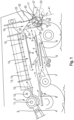
- Fig. 1 shows a combine harvester 1 shown schematically.
- a harvesting head not shown here, is mounted on a front of the combine harvester 1 and supplies a stream 4 of raw crop material to a tangential threshing unit 5 via an inclined conveyor 3.
- a first intermediate crop stream 6 is deposited in the tangential threshing unit 5, which in the area of a cleaning device 7 of any design is divided into a crop stream consisting essentially of grains, hereinafter referred to as grain portion 8, and a substantially Crop stream consisting of short straw and chaff, hereinafter simply referred to as chaff portion 9, is separated.
- At least one further intermediate crop stream 10 is fed from one or more threshing elements 11, 12 to a grain-straw separating device 14, which in the embodiment is designed as an axial flow rotor 13.
- the crop stream 10 is divided into a partial stream 15 of grain, short straw and chaff, which exits along the axial flow rotor 13 via jacket openings thereof and is combined with the first intermediate crop stream 6 in the cleaning device 7, and a second crop stream which consists essentially of long-stemmed straw and is therefore referred to below as straw portion 16.
- An outlet region 19, at which the straw portion 16 exits from the axial flow rotor 13, is located at a rear end thereof.
- a shredding device 17 for chopping the straw portion 16 is arranged under the outlet area 19.
- the shredding device 17 comprises a chopping rotor 2, which is aligned transversely to the direction of travel FR of the combine harvester 1 about an axis 18 in the perspective of the Fig. 1 is rotationally driven in the counterclockwise direction, and a housing with housing sections 25, 26 which, separated from one another by inlet and outlet openings, extend on a substantially cylindrical surface around the chopping rotor 2.
- the chopping rotor 2 comprises a central shaft to which a plurality of chopping knives 20 are each pivotally connected about an axis parallel to the axis 18.
- a channel 22 extends essentially vertically, so that the straw portion 16 moves through the channel 22, driven by its own weight, towards the shredding device 17.
- the width of the channel 22 in the transverse direction of the combine harvester 1 corresponds to the length of the chopping rotor 2 in the direction of the axis 18.
- the separating device 14 can comprise several, typically two, axial flow rotors 13 next to one another.
- the channel 22 is limited by a rear and a front guide plate 23 and 24 respectively.
- the rear guide plate 23 extends downwards from a rear edge of the outlet region 19 on the separating device 14 and is connected at its lower edge to the housing section 25, which extends concentrically to the axis 18 around the chopping rotor 2.
- An imaginary line 41 which extends through the upper and lower edges of the rear guide plate 23 and beyond its lower edge, divides the circle 21 into a front segment, which contains the axis 18, and a rear segment, the segment height h of which corresponds to at least 10%, better at least 15% of the radius of the circle 21.
- the circle 21 and the rear guide plate 23 form a narrow, acute-angled gusset in which a strong upward air flow driven by the rotating chopping knives 20 promotes the floating and clumping of straw particles.
- the rear guide plate 23 is located in the slipstream of the air flow 42, so that close to the rear guide plate 23 even light particles of the straw portion 16 can penetrate to the chopping rotor 2 and be captured by it.
- the front guide plate 24 extends downwards from a front edge of the outlet area 19 on the separating device 14 and merges at its lower edge into the housing section 26, which extends concentrically to the axis 18 around a front lower quadrant of the chopping rotor 2.
- Counter blades 40 projecting radially inward from the housing section 26 interact with the chopping blades 20 in order to chop up the straw portion 16 fed in via the channel 22 and to feed it to a wide distribution device 27.
- the wide distribution device 24 serves to spread of the chopped straw portion 16 in the width direction behind the combine harvester. It can have any known structure and is therefore not specifically described here.
- Fig.2 shows an enlarged cross-section through the shredding device 17.
- the housing section 25 forms approximately a circular arc that extends from a vertical section 29 downwards to the upper edge of an outlet 30 leading to the wide distribution device 27 and upwards over an arc of 50° to an upper edge 31 from which the rear guide plate 23 extends.
- a tangent that touches the housing section 25 at its upper edge 31 and the rear guide plate 23 form an angle facing the channel 22 and the chopping rotor 2, which causes the rear guide plate 23 to lie in the slipstream of the air flow 42 emanating from the chopping rotor 2.
- Straw particles which slide downwards guided on the rear guide plate 23 thus reach the shredding device 17 at a non-zero speed radially to the axis 18, so that they penetrate into the circle 21 and are caught by the chopping knives 20.
- the housing section 26 is here formed by several successive segments in the circumferential direction of the circle 21.
- One of these segments 28 can be pivotable in a controlled manner against the chopping rotor 2 in order to increase the width of the gap between the chopping knives 20 and the housing section or the friction between the relevant segment and the To control straw and thus influence the efficiency of the chopping process.
- the rear guide plate 23 is hinged to the housing section 26 at the upper edge 31 and, when the chopping rotor 2 is at a standstill, is Fig.2 shown position into one in Fig.1 position shown in dashed lines, in which an upper edge of the rear guide plate 23 rests against a shoulder 32 of the front guide plate 23. Access to the shredding device 17 is thus blocked.
- the wide distribution device 27 can also be in this state, as in Fig.1 shown in dashed lines, be pivoted downwards to facilitate the sliding of the straw portion on a flat upper side 33 of the wide distribution device 27.
- the housing section 25 comprises a stationary segment 34 and a segment 35 which can be displaced in the circumferential direction of the chopper rotor 2 against the segment 34 and forms the upper edge 31 with the aid of an actuator (not shown), and the rear guide plate 23 comprises segments 36, 37 which can be telescopically displaceable relative to one another, of which the lower 36 is articulated to the upper edge 31 of the segment 35 and the upper 37 to the separating device 14.
- the rear baffle 23 can thus become shorter or longer in accordance with an increase or decrease in the expansion of the housing section 25 and thereby pivot about an axis 38 which connects it to the outlet region 19.
- the guide plate 23 is adjustable between one in Fig.
- a control unit can be set up, the actuator depending on a type that is automatically identified or entered by a user or type of crop, a mass flow of one of the various crop flows described above measured at any suitable location in the combine, the moisture content of the crop, etc.
Landscapes
- Life Sciences & Earth Sciences (AREA)
- Environmental Sciences (AREA)
- Threshing Machine Elements (AREA)
Applications Claiming Priority (1)
| Application Number | Priority Date | Filing Date | Title |
|---|---|---|---|
| DE102022123913.6A DE102022123913A1 (de) | 2022-09-19 | 2022-09-19 | Mähdrescher mit Zerkleinerungseinrichtung |
Publications (1)
| Publication Number | Publication Date |
|---|---|
| EP4344530A1 true EP4344530A1 (fr) | 2024-04-03 |
Family
ID=87426880
Family Applications (1)
| Application Number | Title | Priority Date | Filing Date |
|---|---|---|---|
| EP23186574.2A Pending EP4344530A1 (fr) | 2022-09-19 | 2023-07-20 | Moissonneuse-batteuse avec dispositif de broyage |
Country Status (3)
| Country | Link |
|---|---|
| US (1) | US20240090375A1 (fr) |
| EP (1) | EP4344530A1 (fr) |
| DE (1) | DE102022123913A1 (fr) |
Citations (5)
| Publication number | Priority date | Publication date | Assignee | Title |
|---|---|---|---|---|
| DE10130652A1 (de) * | 2001-06-27 | 2003-01-30 | Claas Selbstfahr Erntemasch | Mähdrescher mit Wurfgebläse |
| US20040176151A1 (en) * | 2003-03-07 | 2004-09-09 | Jose Gryspeerdt | Combine harvester |
| EP1232683B2 (fr) | 2001-02-16 | 2007-04-11 | CLAAS Selbstfahrende Erntemaschinen GmbH | Eléments entraîneurs ef dispositif broyeur pour machine agricole |
| EP3409095A1 (fr) * | 2017-05-30 | 2018-12-05 | Deere & Company | Moissonneuse-batteuse agricole comportant un rotor de hacheur inversé |
| DE102020112187A1 (de) * | 2020-05-06 | 2021-11-11 | Claas Selbstfahrende Erntemaschinen Gmbh | Luftzuführung Strohhäcksler |
-
2022
- 2022-09-19 DE DE102022123913.6A patent/DE102022123913A1/de active Pending
-
2023
- 2023-07-20 EP EP23186574.2A patent/EP4344530A1/fr active Pending
- 2023-09-19 US US18/369,925 patent/US20240090375A1/en active Pending
Patent Citations (5)
| Publication number | Priority date | Publication date | Assignee | Title |
|---|---|---|---|---|
| EP1232683B2 (fr) | 2001-02-16 | 2007-04-11 | CLAAS Selbstfahrende Erntemaschinen GmbH | Eléments entraîneurs ef dispositif broyeur pour machine agricole |
| DE10130652A1 (de) * | 2001-06-27 | 2003-01-30 | Claas Selbstfahr Erntemasch | Mähdrescher mit Wurfgebläse |
| US20040176151A1 (en) * | 2003-03-07 | 2004-09-09 | Jose Gryspeerdt | Combine harvester |
| EP3409095A1 (fr) * | 2017-05-30 | 2018-12-05 | Deere & Company | Moissonneuse-batteuse agricole comportant un rotor de hacheur inversé |
| DE102020112187A1 (de) * | 2020-05-06 | 2021-11-11 | Claas Selbstfahrende Erntemaschinen Gmbh | Luftzuführung Strohhäcksler |
Also Published As
| Publication number | Publication date |
|---|---|
| DE102022123913A1 (de) | 2024-03-21 |
| US20240090375A1 (en) | 2024-03-21 |
Similar Documents
| Publication | Publication Date | Title |
|---|---|---|
| DE3042734C3 (de) | Mähdrescher | |
| EP1219164B1 (fr) | Procédé et dispositif pour convoyer des récoltes dans une machine agricole | |
| EP3662738B1 (fr) | Moissonneuse-batteuse automotrice | |
| DE202008018219U1 (de) | Streuelement und Mähdrescher mit Steuelement | |
| EP0521280B1 (fr) | Séparateur axial | |
| DE2430718B2 (de) | Mähdrescher | |
| EP2298061A2 (fr) | Procédé de répartition d'un flux de matière sur un champ et dispositif de hachage et de répartition | |
| DE2943840C2 (fr) | ||
| DE2118914A1 (de) | Aus wenigstens einem Paar zusammenwirkender Mähkreisel bestehendes Mähwerk und nachgeschaltetem Quetschwalzenpaar bestehende Halmgutaufbereitungsmaschine | |
| DE2451186A1 (de) | Zuckerrohrerntemaschine | |
| EP2036422B1 (fr) | Moissonneuse-batteuse dotée d'un système à hacher la paille | |
| EP2071935B1 (fr) | Moissonneuse-batteuse dotée d'un ventilateur de nettoyage | |
| EP3520596B1 (fr) | Moissonneuse-batteuse | |
| DE3415508A1 (de) | Feldhaecksler | |
| EP3714678A1 (fr) | Séparateur axial pour une moissonneuse-batteuse | |
| EP1614339B1 (fr) | Dispositif distributeur de produits | |
| EP4344530A1 (fr) | Moissonneuse-batteuse avec dispositif de broyage | |
| EP3228174B1 (fr) | Rotor d'éjection d'un dispositif de distribution pour une moissonneuse automotrice | |
| DE1241183B (de) | Kombinierte Dresch- und Reinigungsvorrichtung zur Behandlung von Maehgut wie Getreide | |
| DE102020123939A1 (de) | Rotierender siebkasten | |
| EP3721697A1 (fr) | Moissonneuse-batteuse dotée d'un dispositif de nettoyage | |
| DE540030C (de) | Axialdreschmaschine oder Axialdresch- und -strohzerreissmaschine | |
| EP2181578A2 (fr) | Moissonneuse-batteuse et procédé de récolte | |
| DE19653399A1 (de) | Landwirtschaftliche Erntemaschine | |
| EP4338577A1 (fr) | Moissonneuse-batteuse automotrice |
Legal Events
| Date | Code | Title | Description |
|---|---|---|---|
| PUAI | Public reference made under article 153(3) epc to a published international application that has entered the european phase |
Free format text: ORIGINAL CODE: 0009012 |
|
| STAA | Information on the status of an ep patent application or granted ep patent |
Free format text: STATUS: THE APPLICATION HAS BEEN PUBLISHED |
|
| AK | Designated contracting states |
Kind code of ref document: A1 Designated state(s): AL AT BE BG CH CY CZ DE DK EE ES FI FR GB GR HR HU IE IS IT LI LT LU LV MC ME MK MT NL NO PL PT RO RS SE SI SK SM TR |
|
| P01 | Opt-out of the competence of the unified patent court (upc) registered |
Effective date: 20240403 |