EP4344352B1 - Led-lampenwulst und led-lampengruppe - Google Patents
Led-lampenwulst und led-lampengruppe Download PDFInfo
- Publication number
- EP4344352B1 EP4344352B1 EP22211339.1A EP22211339A EP4344352B1 EP 4344352 B1 EP4344352 B1 EP 4344352B1 EP 22211339 A EP22211339 A EP 22211339A EP 4344352 B1 EP4344352 B1 EP 4344352B1
- Authority
- EP
- European Patent Office
- Prior art keywords
- light
- chip
- lamp bead
- emitting body
- led lamp
- Prior art date
- Legal status (The legal status is an assumption and is not a legal conclusion. Google has not performed a legal analysis and makes no representation as to the accuracy of the status listed.)
- Active
Links
Images
Classifications
-
- H—ELECTRICITY
- H05—ELECTRIC TECHNIQUES NOT OTHERWISE PROVIDED FOR
- H05B—ELECTRIC HEATING; ELECTRIC LIGHT SOURCES NOT OTHERWISE PROVIDED FOR; CIRCUIT ARRANGEMENTS FOR ELECTRIC LIGHT SOURCES, IN GENERAL
- H05B45/00—Circuit arrangements for operating light-emitting diodes [LED]
- H05B45/20—Controlling the colour of the light
-
- H—ELECTRICITY
- H10—SEMICONDUCTOR DEVICES; ELECTRIC SOLID-STATE DEVICES NOT OTHERWISE PROVIDED FOR
- H10H—INORGANIC LIGHT-EMITTING SEMICONDUCTOR DEVICES HAVING POTENTIAL BARRIERS
- H10H20/00—Individual inorganic light-emitting semiconductor devices having potential barriers, e.g. light-emitting diodes [LED]
- H10H20/80—Constructional details
- H10H20/85—Packages
- H10H20/857—Interconnections, e.g. lead-frames, bond wires or solder balls
-
- H—ELECTRICITY
- H10—SEMICONDUCTOR DEVICES; ELECTRIC SOLID-STATE DEVICES NOT OTHERWISE PROVIDED FOR
- H10H—INORGANIC LIGHT-EMITTING SEMICONDUCTOR DEVICES HAVING POTENTIAL BARRIERS
- H10H20/00—Individual inorganic light-emitting semiconductor devices having potential barriers, e.g. light-emitting diodes [LED]
- H10H20/80—Constructional details
- H10H20/85—Packages
- H10H20/8506—Containers
-
- H—ELECTRICITY
- H10—SEMICONDUCTOR DEVICES; ELECTRIC SOLID-STATE DEVICES NOT OTHERWISE PROVIDED FOR
- H10H—INORGANIC LIGHT-EMITTING SEMICONDUCTOR DEVICES HAVING POTENTIAL BARRIERS
- H10H29/00—Integrated devices, or assemblies of multiple devices, comprising at least one light-emitting semiconductor element covered by group H10H20/00
- H10H29/10—Integrated devices comprising at least one light-emitting semiconductor component covered by group H10H20/00
-
- Y—GENERAL TAGGING OF NEW TECHNOLOGICAL DEVELOPMENTS; GENERAL TAGGING OF CROSS-SECTIONAL TECHNOLOGIES SPANNING OVER SEVERAL SECTIONS OF THE IPC; TECHNICAL SUBJECTS COVERED BY FORMER USPC CROSS-REFERENCE ART COLLECTIONS [XRACs] AND DIGESTS
- Y02—TECHNOLOGIES OR APPLICATIONS FOR MITIGATION OR ADAPTATION AGAINST CLIMATE CHANGE
- Y02B—CLIMATE CHANGE MITIGATION TECHNOLOGIES RELATED TO BUILDINGS, e.g. HOUSING, HOUSE APPLIANCES OR RELATED END-USER APPLICATIONS
- Y02B20/00—Energy efficient lighting technologies, e.g. halogen lamps or gas discharge lamps
- Y02B20/40—Control techniques providing energy savings, e.g. smart controller or presence detection
Definitions
- the present application relates to the technical field of LED lamp beads, in particular to an LED lamp bead and an LED lamp group.
- Each of the existing Symphony point-controlled lamp beads comprises a signal input end and a signal output end.
- the welding pin brackets need to be arranged at the signal input end and the signal output end respectively, and the signal output line is needed to be welded, so as to make the welding pin bracket at the signal output end of one lamp bead connect with the welding pin bracket at the signal input end of the adjacent lamp bead at the rear end thereof.
- This packaging structure of the lamp bead not only has more packaging processes, but also has poor adaptability when the lamp bead is lit by the signal.
- CN205807035U mainly discloses a string of copper wire lamps which can control the luminescence mode.
- the purpose of the present application is to provide an LED lamp bead and an LED lamp group.
- the LED lamp bead works independently, ensuring that each LED lamp bead in the LED lamp group can be lit under normal conditions and have a good adaptability.
- the drive circuit comprises an IC chip and a light-emitting body control chip connected thereto, and the light-emitting body control chip corresponds to the light-emitting body; the IC chip is configured for acquiring the lamp bead trigger signal and sending the lamp bead trigger signal to the light-emitting body control chip; and the light-emitting body control chip is configured for receiving the lamp bead trigger signal to trigger the light-emitting body to emit light.
- the embodiment of the present application provides a third possible embodiment of the first aspect, wherein communication contacts and a signal input contact are provided on the IC chip; the signal input contact is configured for connecting with the input pin, for transmitting the lamp bead trigger signal to the IC chip; and the IC chip is configured to send the lamp bead trigger signal to the light-emitting body control chip through the communication contacts, so as to trigger the light-emitting body to emit light.
- the embodiment of the present application provides a fifth possible embodiment of the first aspect, wherein the plurality of light-emitting bodies of different colors comprise R, G, and B light-emitting bodies.
- the embodiment of the present application provides a sixth possible embodiment of the first aspect, wherein the power supply pins comprise a positive pin and a negative pin, the positive pin is connected with the light-emitting body control chip, and the negative pin is connected with the IC chip, wherein the IC chip further comprises an IC positive electrode and an IC negative electrode, the IC positive electrode is connected to the positive pin, and the IC negative electrode is connected to the negative pin; and the light-emitting body control chip comprises a chip positive electrode and a chip negative electrode, the chip positive electrode is connected to the positive pin, and the chip negative electrode is connected to the IC chip.
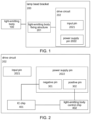
- each LED lamp bead comprises a drive circuit 202.
- the drive circuit 202 drives the light-emitting body 101 to emit light according to the lamp bead trigger signal, wherein the drive circuit 202 is fixed to the light-emitting body fixing structure 201, so that the light-emitting body 101 and the drive circuit 202 are connected with each other.
- the LED lamp bead provided by the embodiment of the present application drives the light-emitting body 101 to emit light through the drive circuit 202, and each LED lamp bead included in the LED lamp group does not need to realize the light-emitting work according to the signal output of other LED lamp beads.
- Each of the lamp beads works independently, ensuring that each LED light bead in the LED light group can be lit under normal conditions.
- the embodiments of the present application further provide another LED lamp bead.
- the another LED lamp bead provided by the embodiments of the present application further comprises a lamp bead cover 102, the lamp bead cover 102 is installed on the light-emitting body fixing structure 201, for forming the lamp cover structure of the light-emitting body 101.
- the embodiment of the present application is mainly to introduce the specific structure of the drive circuit 202.
- FIG. 2 shows a schematic structural diagram of another LED lamp bead provided by the present application, wherein FIG. 2 is the schematic structural diagram of the drive circuit 202 of the LED lamp bead. As shown in FIG.
- the above-mentioned drive circuit 202 comprises an IC chip 401 and a light-emitting body control chip 402 connected to the IC chip 401; the light-emitting body control chip 402 corresponds to the light-emitting body 101; the IC chip 401 is used for acquiring the lamp bead trigger signal and sending it to the light-emitting body control chip 402; the light-emitting body control chip 402 is used for receiving the lamp bead trigger signal to trigger the light-emitting body 101 to emit light.
- the above-mentioned power supply pins 2022 comprise a positive pin 302 and a negative pin 301
- the positive pin 302 is connected to the light-emitting body control chip 402
- the negative pin 301 is connected to the IC chip 401.
- the IC chip 401 is provided thereon with communication contacts and a signal input contact 2; the signal input contact is used to connect with the input pin 2021 for transmitting the lamp bead trigger signal to the IC chip 401; the IC chip 401 is used to send a lamp bead trigger signal to the light-emitting body control chip 402 through the communication contacts, so as to trigger the light-emitting body 101 to emit light.
- light-emitting body 101 of the LED lamp bead comprises a plurality of light-emitting bodies 101 of different colors
- the light-emitting body control chip 402 of the drive circuit 202 comprises light-emitting body sub-chips corresponding to individual light-emitting bodies 101.
- the light-emitting body sub-chip is used for receiving the lamp bead trigger signal to trigger the corresponding light-emitting body 101 to emit light.
- the communication contacts of the IC chip 401 comprise communication contacts corresponding to individual light-emitting sub-chips, and each communication contact is connected to the corresponding light-emitting sub-chip.
- the above-mentioned plurality of light-emitting bodies 101 of different colors may comprise R, G, and B light-emitting bodies.
- the above-mentioned light-emitting sub-chips comprise the red light-emitting sub-chip corresponding to the R light-emitting body, the green light-emitting sub-chip corresponding to the G light-emitting body, and the blue light-emitting sub-chip corresponding to the B light-emitting body.
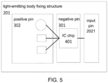
- FIG. 3 is a schematic diagram of the specific structure of the drive circuit 202.
- a plurality of light-emitting bodies 101 of different colors including R, G, and B light-emitting bodies are used as an example for illustration.
- the communication contacts of the IC chip 401 comprise communication contacts corresponding respectively to the above three light-emitting sub-chips.
- four chip structures are shown in FIG. 3 . Each of the three chip structures on the left is one of the three light-emitting sub-chips above. These three light-emitting sub-chips are all connected to the positive pin 302 of the power supply pin 2022.
- the light-emitting body control chip 402 comprises a chip positive electrode and a chip negative electrode.
- the chip negative electrode 4 of the red light-emitting sub-chip is disposed on the top of the red light-emitting sub-chip
- the chip negative electrode 5 of the green light-emitting sub-chip is disposed on the right side of the green light-emitting sub-chip
- the chip negative electrode 6 of the blue light-emitting sub-chip is disposed on the right side of the blue light-emitting sub-chip.
- the chip negative electrodes of the three light-emitting sub-chips are respectively connected to individual communication contacts of the IC chip 401.
- the IC chip 401 further comprises an IC positive electrode and an IC negative electrode.
- the contact 3 in FIG. 3 is the above-mentioned IC positive electrode
- the contact 1 is the above-mentioned IC negative electrode
- the IC positive electrode is connected to the positive pin 302 of the power supply pin 2022
- the IC negative electrode is connected to the negative pin 301 of the power supply pin 2022.
- the IC chip 401 and the light-emitting body control chip 402 in the LED lamp bead provided by the embodiment of the present application are connected by bonding wires, and the corresponding connections between the IC chip 401 and the positive pin 302 and the negative pin 301 are also performed by bonding wires.
- the above-mentioned signal input contact 2 is also connected to the input pin 2021 by bonding wire.
- Another LED lamp bead provided by the present application is provided with an IC chip 401 and a light-emitting body control chip 402.
- the IC chip 401 receives the lamp bead trigger signal through the input pin 2021, and drives the light-emitting body control chip 402 through the communication contact according to the lamp bead trigger signal, so as to drive the light-emitting body 101 to light up.
- the IC chip 401 is connected to the negative pin 301 of the power supply pin 2022, and the light-emitting body control chip 402 is connected to the positive pin 302 of the power supply pin 2022.
- the lamp bead trigger signal received from the input pin 2021 forms a closed signal loop between the IC chip 401 and the light-emitting body control chip 402.
- an embodiment of the present application further provides an LED lamp group, wherein the LED lamp group is provided with a plurality of LED lamp beads as shown in any one of FIG. 1 to FIG. 5 .
- the LED lamp group can determine the lighting mode of each LED lamp bead according to the preset use requirements.
- the LED lamp group provided by the embodiment of the present application has the same technical features as the LED lamp bead provided by the above-mentioned embodiments, so that it can also solve the same technical problems and achieve the same technical effects.
- Those skilled in the art can clearly understand that, for the convenience and brevity of the description, the specific structure of the LED lamp group described above can be obtained by referring to the corresponding structure in the foregoing embodiments of the LED lamp bead, which will not be repeated here.
- connection should be understood in a broad sense.
- it may be a fixed connection, a detachable connection, or an integral connection; or may be a mechanical connection, or may also be an electrical connection; or may be a direct connection, or may also be an indirect connection through an intermediate medium, or may be an internal communication between two elements.
- connection may be a fixed connection, a detachable connection, or an integral connection; or may be a mechanical connection, or may also be an electrical connection; or may be a direct connection, or may also be an indirect connection through an intermediate medium, or may be an internal communication between two elements.
Landscapes
- Led Device Packages (AREA)
- Arrangement Of Elements, Cooling, Sealing, Or The Like Of Lighting Devices (AREA)
- Fastening Of Light Sources Or Lamp Holders (AREA)
Claims (9)
- LED-Lampenwulst, umfassend einen lichtemittierenden Körper (101) und eine Lampenwulsthalterung (200), wobei die Lampenwulsthalterung (200) eine Befestigungskonstruktion für einen lichtemittierenden Körper (201) und eine Ansteuerschaltung (202) umfasst;die Befestigungskonstruktion für einen lichtemittierenden Körper (201) zum Befestigen des lichtemittierenden Körpers (101) konfiguriert ist und die Ansteuerschaltung (202) mit dem lichtemittierenden Körper (101) verbunden ist, um den lichtemittierenden Körper (101) anzusteuern, um Licht als Reaktion auf ein Lampenwulstauslösesignal zu emittieren; unddie Ansteuerschaltung (202) einen Eingabestift (2021) und Stromversorgungsstifte (2022) umfasst, die Stromversorgungsstifte (2022) mit einer Stromversorgung verbunden sind und der Eingabestift (2021) so konfiguriert ist, dass er das Lampenwulstauslösesignal empfängt und an die Ansteuerschaltung (202) überträgt, sodass die Ansteuerschaltung (202) den lichtemittierenden Körper (101) ansteuert, um Licht zu emittieren; dadurch gekennzeichnet, dass die Ansteuerschaltung (202) einen IC-Chip (401) und einen mit dem IC-Chip (401) verbundenen Steuerchip für einen lichtemittierenden Körper (402) umfasst und der Steuerchip für einen lichtemittierenden Körper (402) dem lichtemittierenden Körper (101) entspricht;der IC-Chip (401) so konfiguriert ist, dass er das Lampenwulstauslösesignal erfasst und das Lampenwulstauslösesignal an den Steuerchip für einen lichtemittierenden Körper (402) sendet; undder Steuerchip für einen lichtemittierenden Körper (402) zum Empfangen des Lampenwulstauslösesignals konfiguriert ist, um auszulösen, dass der lichtemittierende Körper (101) Licht emittiert.
- LED-Lampenwulst nach Anspruch 1, wobei der LED-Lampenwulst ferner eine Lampenwulstabdeckung (102) umfasst und die Lampenwulstabdeckung (102) auf der Befestigungskonstruktion für einen lichtemittierenden Körper (201) montiert ist, um eine Lampenabdeckkonstruktion des lichtemittierenden Körpers (101) zu bilden.
- LED-Lampenwulst nach Anspruch 1, wobei auf dem IC-Chip (401) Kommunikationskontakte und ein Signaleingabekontakt (2) bereitgestellt sind;der Signaleingabekontakt (2) so konfiguriert ist, dass er sich mit dem Eingabestift (2021) verbindet, um das Lampenwulstauslösesignal an den IC-Chip (401) zu übertragen; undder IC-Chip (401) so konfiguriert ist, dass er das Lampenwulstauslösesignal durch die Kommunikationskontakte an den Steuerchip für einen lichtemittierenden Körper (402) sendet, um auszulösen, dass der lichtemittierende Körper (101) Licht emittiert.
- LED-Lampenwulst nach Anspruch 3, wobei der lichtemittierende Körper (101) eine Vielzahl von lichtemittierenden Körpern unterschiedlicher Farben umfasst und der Steuerchip für einen lichtemittierenden Körper (402) lichtemittierende Unterchips umfasst, die individuellen lichtemittierenden Körpern entsprechen;jeder der lichtemittierenden Unterchips so konfiguriert ist, dass er das Lampenwulstauslösesignal empfängt, um auszulösen, dass der entsprechende lichtemittierende Körper (101) Licht emittiert; unddie Kommunikationskontakte des IC-Chips (401) Kommunikationskontakte umfassen, die individuellen lichtemittierenden Unterchips entsprechen, und jeder der Kommunikationskontakte mit einem entsprechenden lichtemittierenden Unterchip verbunden ist.
- LED-Lampenwulst nach Anspruch 4, wobei die Vielzahl von lichtemittierenden Körpern unterschiedlicher Farbe R-, G- und B-lichtemittierende Körper umfasst.
- LED-Lampenwulst nach Anspruch 1, wobei die Stromversorgungsstifte (2022) einen positiven Stift (302) und einen negativen Stift (301) umfassen, der positive Stift (302) mit dem Steuerchip für einen lichtemittierenden Körper (402) verbunden ist und der negative Stift (301) mit dem IC-Chip (401) verbunden ist,wobei der IC-Chip (401) ferner eine IC-positive Elektrode (3) und eine IC-negative Elektrode (1) umfasst, die IC-positive Elektrode (3) mit dem positiven Stift (302) verbunden ist und die IC-negative Elektrode (1) mit dem negativen Stift (301) verbunden ist; undder Steuerchip für einen lichtemittierenden Körper (402) eine Chip-positive Elektrode und eine Chip-negative Elektrode umfasst, die Chip-positive Elektrode mit dem positiven Stift (302) verbunden ist und die Chip-negative Elektrode mit dem IC-Chip (401) verbunden ist.
- LED-Lampenwulst nach Anspruch 6, wobei der positive Stift (302), der negative Stift (301) und der Eingabestift (2021) horizontal in Folge von links nach rechts angeordnet sind.
- LED-Lampenwulst nach Anspruch 1, wobei die Befestigungskonstruktion für einen lichtemittierenden Körper (201) eine Plug-in-Konstruktion oder eine Patch-Konstruktion umfasst.
- LED-Lampengruppe, dadurch gekennzeichnet, dass der LED-Lampengruppe eine Vielzahl von LED-Lampenwülsten nach einem der Ansprüche 1 bis 8 bereitgestellt ist.
Applications Claiming Priority (1)
| Application Number | Priority Date | Filing Date | Title |
|---|---|---|---|
| CN202222552096.5U CN219263990U (zh) | 2022-09-26 | 2022-09-26 | Led灯珠和led灯组 |
Publications (3)
| Publication Number | Publication Date |
|---|---|
| EP4344352A1 EP4344352A1 (de) | 2024-03-27 |
| EP4344352B1 true EP4344352B1 (de) | 2025-07-02 |
| EP4344352C0 EP4344352C0 (de) | 2025-07-02 |
Family
ID=84389019
Family Applications (1)
| Application Number | Title | Priority Date | Filing Date |
|---|---|---|---|
| EP22211339.1A Active EP4344352B1 (de) | 2022-09-26 | 2022-12-05 | Led-lampenwulst und led-lampengruppe |
Country Status (3)
| Country | Link |
|---|---|
| US (1) | US11824149B1 (de) |
| EP (1) | EP4344352B1 (de) |
| CN (1) | CN219263990U (de) |
Families Citing this family (1)
| Publication number | Priority date | Publication date | Assignee | Title |
|---|---|---|---|---|
| CN220554121U (zh) * | 2023-08-01 | 2024-03-01 | 江西奥赛光电有限公司 | Led灯珠和led灯组 |
Family Cites Families (7)
| Publication number | Priority date | Publication date | Assignee | Title |
|---|---|---|---|---|
| CN105428345A (zh) * | 2015-12-09 | 2016-03-23 | 东莞市晨彩照明科技有限公司 | 多发光点的led灯珠 |
| CN205807035U (zh) * | 2016-06-20 | 2016-12-14 | 台州海之大电子科技有限公司 | 一种可控制发光模式的铜线灯串 |
| CN112117266A (zh) * | 2020-10-19 | 2020-12-22 | 厦门强力巨彩光电科技有限公司 | Led灯珠封装模组和led显示屏 |
| CN112512168A (zh) * | 2020-12-21 | 2021-03-16 | 江苏镭科照明科技有限公司 | Rgb-ww同步智能美耐灯 |
| CN218160373U (zh) * | 2021-08-19 | 2022-12-27 | 深圳市晶泓科技有限公司 | 一种led灯珠及透明led显示屏 |
| CN216450634U (zh) * | 2021-11-04 | 2022-05-06 | 中山市木林森电子有限公司 | 一种基于通用支架设计的正向芯片幻彩灯珠 |
| CN218586009U (zh) * | 2022-07-22 | 2023-03-07 | 深圳市两岸光电科技有限公司 | 一种贴片式rgb加白光内置ic幻彩灯珠 |
-
2022
- 2022-09-26 CN CN202222552096.5U patent/CN219263990U/zh active Active
- 2022-12-05 EP EP22211339.1A patent/EP4344352B1/de active Active
- 2022-12-13 US US18/080,386 patent/US11824149B1/en active Active
Also Published As
| Publication number | Publication date |
|---|---|
| EP4344352A1 (de) | 2024-03-27 |
| EP4344352C0 (de) | 2025-07-02 |
| US11824149B1 (en) | 2023-11-21 |
| CN219263990U (zh) | 2023-06-27 |
Similar Documents
| Publication | Publication Date | Title |
|---|---|---|
| CN111106226A (zh) | 一种内封ic的led灯珠 | |
| CN210956723U (zh) | 一种内封ic的led灯珠 | |
| EP4344352B1 (de) | Led-lampenwulst und led-lampengruppe | |
| US20240102637A1 (en) | High-voltage point control lamp string and window curtain system | |
| CN217382611U (zh) | 直插式点控灯及灯串结构 | |
| CN220554121U (zh) | Led灯珠和led灯组 | |
| CN117457638A (zh) | 一种可内置控制芯片的彩色led灯珠支架 | |
| CN113921688A (zh) | 一种新型多彩led光源 | |
| CN217562564U (zh) | 一种三色led芯片的封装结构 | |
| CN209876620U (zh) | 一种发光灯条及油烟机 | |
| CN219873584U (zh) | 一种led器件及led模组 | |
| CN219738954U (zh) | 显示面板以及显示器 | |
| CN101330788B (zh) | 一种集成双向冗余控制装置的led发光元件 | |
| CN214378435U (zh) | Led灯珠 | |
| CN221080040U (zh) | 一种发光led灯珠及发光器件 | |
| US20240373531A1 (en) | Led lamp with boss and surge protection module | |
| CN215722663U (zh) | 可连接灯串及照明装置 | |
| CN220474320U (zh) | 一种图形识别ic控制的led制品及照明模组 | |
| KR101515366B1 (ko) | 이중계 쌍심형 led 및 그 제조 방법과 이를 이용한 철도 신호기 | |
| CN223193532U (zh) | 一种led驱动电路及封装结构、显示屏 | |
| CN117410283A (zh) | 一种内置控制芯片的彩色led灯珠 | |
| CN222142821U (zh) | 白光、暖白光双色点控灯珠的防串色装置及系统 | |
| CN223540886U (zh) | 一种led灯珠器件 | |
| EP4417866A1 (de) | Lichtstrukturverbindungsvorrichtung und -system | |
| CN213686272U (zh) | 一种led灯珠结构 |
Legal Events
| Date | Code | Title | Description |
|---|---|---|---|
| STAA | Information on the status of an ep patent application or granted ep patent |
Free format text: STATUS: EXAMINATION IS IN PROGRESS |
|
| PUAI | Public reference made under article 153(3) epc to a published international application that has entered the european phase |
Free format text: ORIGINAL CODE: 0009012 |
|
| 17P | Request for examination filed |
Effective date: 20221205 |
|
| AK | Designated contracting states |
Kind code of ref document: A1 Designated state(s): AL AT BE BG CH CY CZ DE DK EE ES FI FR GB GR HR HU IE IS IT LI LT LU LV MC ME MK MT NL NO PL PT RO RS SE SI SK SM TR |
|
| GRAP | Despatch of communication of intention to grant a patent |
Free format text: ORIGINAL CODE: EPIDOSNIGR1 |
|
| STAA | Information on the status of an ep patent application or granted ep patent |
Free format text: STATUS: GRANT OF PATENT IS INTENDED |
|
| INTG | Intention to grant announced |
Effective date: 20250213 |
|
| GRAS | Grant fee paid |
Free format text: ORIGINAL CODE: EPIDOSNIGR3 |
|
| GRAA | (expected) grant |
Free format text: ORIGINAL CODE: 0009210 |
|
| STAA | Information on the status of an ep patent application or granted ep patent |
Free format text: STATUS: THE PATENT HAS BEEN GRANTED |
|
| AK | Designated contracting states |
Kind code of ref document: B1 Designated state(s): AL AT BE BG CH CY CZ DE DK EE ES FI FR GB GR HR HU IE IS IT LI LT LU LV MC ME MK MT NL NO PL PT RO RS SE SI SK SM TR |
|
| REG | Reference to a national code |
Ref country code: GB Ref legal event code: FG4D |
|
| REG | Reference to a national code |
Ref country code: CH Ref legal event code: EP |
|
| REG | Reference to a national code |
Ref country code: DE Ref legal event code: R096 Ref document number: 602022016815 Country of ref document: DE |
|
| REG | Reference to a national code |
Ref country code: IE Ref legal event code: FG4D |
|
| U01 | Request for unitary effect filed |
Effective date: 20250724 |
|
| RAP4 | Party data changed (patent owner data changed or rights of a patent transferred) |
Owner name: SHANGYOU JIAYI LIGHTING PRODUCT CO., LTD. |
|
| U07 | Unitary effect registered |
Designated state(s): AT BE BG DE DK EE FI FR IT LT LU LV MT NL PT RO SE SI Effective date: 20250812 |
|
| REG | Reference to a national code |
Ref country code: CH Ref legal event code: Y10 Free format text: ST27 STATUS EVENT CODE: U-0-0-Y10-Y00 (AS PROVIDED BY THE NATIONAL OFFICE) Effective date: 20251001 |
|
| REG | Reference to a national code |
Ref country code: CH Ref legal event code: U11 Free format text: ST27 STATUS EVENT CODE: U-0-0-U10-U11 (AS PROVIDED BY THE NATIONAL OFFICE) Effective date: 20260101 |
|
| PG25 | Lapsed in a contracting state [announced via postgrant information from national office to epo] |
Ref country code: IS Free format text: LAPSE BECAUSE OF FAILURE TO SUBMIT A TRANSLATION OF THE DESCRIPTION OR TO PAY THE FEE WITHIN THE PRESCRIBED TIME-LIMIT Effective date: 20251102 |
|
| PG25 | Lapsed in a contracting state [announced via postgrant information from national office to epo] |
Ref country code: NO Free format text: LAPSE BECAUSE OF FAILURE TO SUBMIT A TRANSLATION OF THE DESCRIPTION OR TO PAY THE FEE WITHIN THE PRESCRIBED TIME-LIMIT Effective date: 20251002 |
|
| PG25 | Lapsed in a contracting state [announced via postgrant information from national office to epo] |
Ref country code: HR Free format text: LAPSE BECAUSE OF FAILURE TO SUBMIT A TRANSLATION OF THE DESCRIPTION OR TO PAY THE FEE WITHIN THE PRESCRIBED TIME-LIMIT Effective date: 20250702 |