EP4343200A1 - Dispositif d'éclairage ou dispositif d'éclairage pour un phare de véhicule automobile - Google Patents
Dispositif d'éclairage ou dispositif d'éclairage pour un phare de véhicule automobile Download PDFInfo
- Publication number
- EP4343200A1 EP4343200A1 EP22196548.6A EP22196548A EP4343200A1 EP 4343200 A1 EP4343200 A1 EP 4343200A1 EP 22196548 A EP22196548 A EP 22196548A EP 4343200 A1 EP4343200 A1 EP 4343200A1
- Authority
- EP
- European Patent Office
- Prior art keywords
- light
- sub
- total reflection
- light exit
- area
- Prior art date
- Legal status (The legal status is an assumption and is not a legal conclusion. Google has not performed a legal analysis and makes no representation as to the accuracy of the status listed.)
- Pending
Links
- 230000003287 optical effect Effects 0.000 claims abstract description 10
- 230000008878 coupling Effects 0.000 claims description 12
- 238000010168 coupling process Methods 0.000 claims description 12
- 238000005859 coupling reaction Methods 0.000 claims description 12
- 230000005855 radiation Effects 0.000 claims description 9
- 230000011664 signaling Effects 0.000 claims 1
- 230000000694 effects Effects 0.000 description 3
- 239000000835 fiber Substances 0.000 description 3
- 230000003760 hair shine Effects 0.000 description 2
- 238000009434 installation Methods 0.000 description 2
- 241001516739 Platonia insignis Species 0.000 description 1
- 230000001419 dependent effect Effects 0.000 description 1
- 238000000265 homogenisation Methods 0.000 description 1
- 238000005286 illumination Methods 0.000 description 1
- 239000007787 solid Substances 0.000 description 1
- 239000012780 transparent material Substances 0.000 description 1
Images


Classifications
-
- F—MECHANICAL ENGINEERING; LIGHTING; HEATING; WEAPONS; BLASTING
- F21—LIGHTING
- F21S—NON-PORTABLE LIGHTING DEVICES; SYSTEMS THEREOF; VEHICLE LIGHTING DEVICES SPECIALLY ADAPTED FOR VEHICLE EXTERIORS
- F21S43/00—Signalling devices specially adapted for vehicle exteriors, e.g. brake lamps, direction indicator lights or reversing lights
- F21S43/10—Signalling devices specially adapted for vehicle exteriors, e.g. brake lamps, direction indicator lights or reversing lights characterised by the light source
- F21S43/13—Signalling devices specially adapted for vehicle exteriors, e.g. brake lamps, direction indicator lights or reversing lights characterised by the light source characterised by the type of light source
- F21S43/14—Light emitting diodes [LED]
-
- F—MECHANICAL ENGINEERING; LIGHTING; HEATING; WEAPONS; BLASTING
- F21—LIGHTING
- F21S—NON-PORTABLE LIGHTING DEVICES; SYSTEMS THEREOF; VEHICLE LIGHTING DEVICES SPECIALLY ADAPTED FOR VEHICLE EXTERIORS
- F21S43/00—Signalling devices specially adapted for vehicle exteriors, e.g. brake lamps, direction indicator lights or reversing lights
- F21S43/20—Signalling devices specially adapted for vehicle exteriors, e.g. brake lamps, direction indicator lights or reversing lights characterised by refractors, transparent cover plates, light guides or filters
- F21S43/235—Light guides
- F21S43/236—Light guides characterised by the shape of the light guide
- F21S43/239—Light guides characterised by the shape of the light guide plate-shaped
-
- F—MECHANICAL ENGINEERING; LIGHTING; HEATING; WEAPONS; BLASTING
- F21—LIGHTING
- F21S—NON-PORTABLE LIGHTING DEVICES; SYSTEMS THEREOF; VEHICLE LIGHTING DEVICES SPECIALLY ADAPTED FOR VEHICLE EXTERIORS
- F21S41/00—Illuminating devices specially adapted for vehicle exteriors, e.g. headlamps
- F21S41/20—Illuminating devices specially adapted for vehicle exteriors, e.g. headlamps characterised by refractors, transparent cover plates, light guides or filters
- F21S41/24—Light guides
-
- F—MECHANICAL ENGINEERING; LIGHTING; HEATING; WEAPONS; BLASTING
- F21—LIGHTING
- F21S—NON-PORTABLE LIGHTING DEVICES; SYSTEMS THEREOF; VEHICLE LIGHTING DEVICES SPECIALLY ADAPTED FOR VEHICLE EXTERIORS
- F21S41/00—Illuminating devices specially adapted for vehicle exteriors, e.g. headlamps
- F21S41/10—Illuminating devices specially adapted for vehicle exteriors, e.g. headlamps characterised by the light source
- F21S41/14—Illuminating devices specially adapted for vehicle exteriors, e.g. headlamps characterised by the light source characterised by the type of light source
- F21S41/141—Light emitting diodes [LED]
-
- F—MECHANICAL ENGINEERING; LIGHTING; HEATING; WEAPONS; BLASTING
- F21—LIGHTING
- F21S—NON-PORTABLE LIGHTING DEVICES; SYSTEMS THEREOF; VEHICLE LIGHTING DEVICES SPECIALLY ADAPTED FOR VEHICLE EXTERIORS
- F21S41/00—Illuminating devices specially adapted for vehicle exteriors, e.g. headlamps
- F21S41/10—Illuminating devices specially adapted for vehicle exteriors, e.g. headlamps characterised by the light source
- F21S41/14—Illuminating devices specially adapted for vehicle exteriors, e.g. headlamps characterised by the light source characterised by the type of light source
- F21S41/18—Combination of light sources of different types or shapes
-
- F—MECHANICAL ENGINEERING; LIGHTING; HEATING; WEAPONS; BLASTING
- F21—LIGHTING
- F21S—NON-PORTABLE LIGHTING DEVICES; SYSTEMS THEREOF; VEHICLE LIGHTING DEVICES SPECIALLY ADAPTED FOR VEHICLE EXTERIORS
- F21S41/00—Illuminating devices specially adapted for vehicle exteriors, e.g. headlamps
- F21S41/20—Illuminating devices specially adapted for vehicle exteriors, e.g. headlamps characterised by refractors, transparent cover plates, light guides or filters
- F21S41/285—Refractors, transparent cover plates, light guides or filters not provided in groups F21S41/24 - F21S41/2805
-
- F—MECHANICAL ENGINEERING; LIGHTING; HEATING; WEAPONS; BLASTING
- F21—LIGHTING
- F21S—NON-PORTABLE LIGHTING DEVICES; SYSTEMS THEREOF; VEHICLE LIGHTING DEVICES SPECIALLY ADAPTED FOR VEHICLE EXTERIORS
- F21S41/00—Illuminating devices specially adapted for vehicle exteriors, e.g. headlamps
- F21S41/30—Illuminating devices specially adapted for vehicle exteriors, e.g. headlamps characterised by reflectors
- F21S41/32—Optical layout thereof
-
- F—MECHANICAL ENGINEERING; LIGHTING; HEATING; WEAPONS; BLASTING
- F21—LIGHTING
- F21S—NON-PORTABLE LIGHTING DEVICES; SYSTEMS THEREOF; VEHICLE LIGHTING DEVICES SPECIALLY ADAPTED FOR VEHICLE EXTERIORS
- F21S43/00—Signalling devices specially adapted for vehicle exteriors, e.g. brake lamps, direction indicator lights or reversing lights
- F21S43/10—Signalling devices specially adapted for vehicle exteriors, e.g. brake lamps, direction indicator lights or reversing lights characterised by the light source
- F21S43/13—Signalling devices specially adapted for vehicle exteriors, e.g. brake lamps, direction indicator lights or reversing lights characterised by the light source characterised by the type of light source
- F21S43/15—Strips of light sources
-
- F—MECHANICAL ENGINEERING; LIGHTING; HEATING; WEAPONS; BLASTING
- F21—LIGHTING
- F21S—NON-PORTABLE LIGHTING DEVICES; SYSTEMS THEREOF; VEHICLE LIGHTING DEVICES SPECIALLY ADAPTED FOR VEHICLE EXTERIORS
- F21S43/00—Signalling devices specially adapted for vehicle exteriors, e.g. brake lamps, direction indicator lights or reversing lights
- F21S43/20—Signalling devices specially adapted for vehicle exteriors, e.g. brake lamps, direction indicator lights or reversing lights characterised by refractors, transparent cover plates, light guides or filters
- F21S43/235—Light guides
- F21S43/236—Light guides characterised by the shape of the light guide
- F21S43/241—Light guides characterised by the shape of the light guide of complex shape
-
- F—MECHANICAL ENGINEERING; LIGHTING; HEATING; WEAPONS; BLASTING
- F21—LIGHTING
- F21S—NON-PORTABLE LIGHTING DEVICES; SYSTEMS THEREOF; VEHICLE LIGHTING DEVICES SPECIALLY ADAPTED FOR VEHICLE EXTERIORS
- F21S43/00—Signalling devices specially adapted for vehicle exteriors, e.g. brake lamps, direction indicator lights or reversing lights
- F21S43/20—Signalling devices specially adapted for vehicle exteriors, e.g. brake lamps, direction indicator lights or reversing lights characterised by refractors, transparent cover plates, light guides or filters
- F21S43/235—Light guides
- F21S43/242—Light guides characterised by the emission area
- F21S43/245—Light guides characterised by the emission area emitting light from one or more of its major surfaces
-
- F—MECHANICAL ENGINEERING; LIGHTING; HEATING; WEAPONS; BLASTING
- F21—LIGHTING
- F21S—NON-PORTABLE LIGHTING DEVICES; SYSTEMS THEREOF; VEHICLE LIGHTING DEVICES SPECIALLY ADAPTED FOR VEHICLE EXTERIORS
- F21S43/00—Signalling devices specially adapted for vehicle exteriors, e.g. brake lamps, direction indicator lights or reversing lights
- F21S43/20—Signalling devices specially adapted for vehicle exteriors, e.g. brake lamps, direction indicator lights or reversing lights characterised by refractors, transparent cover plates, light guides or filters
- F21S43/235—Light guides
- F21S43/247—Light guides with a single light source being coupled into the light guide
-
- F—MECHANICAL ENGINEERING; LIGHTING; HEATING; WEAPONS; BLASTING
- F21—LIGHTING
- F21S—NON-PORTABLE LIGHTING DEVICES; SYSTEMS THEREOF; VEHICLE LIGHTING DEVICES SPECIALLY ADAPTED FOR VEHICLE EXTERIORS
- F21S43/00—Signalling devices specially adapted for vehicle exteriors, e.g. brake lamps, direction indicator lights or reversing lights
- F21S43/20—Signalling devices specially adapted for vehicle exteriors, e.g. brake lamps, direction indicator lights or reversing lights characterised by refractors, transparent cover plates, light guides or filters
- F21S43/235—Light guides
- F21S43/249—Light guides with two or more light sources being coupled into the light guide
-
- F—MECHANICAL ENGINEERING; LIGHTING; HEATING; WEAPONS; BLASTING
- F21—LIGHTING
- F21S—NON-PORTABLE LIGHTING DEVICES; SYSTEMS THEREOF; VEHICLE LIGHTING DEVICES SPECIALLY ADAPTED FOR VEHICLE EXTERIORS
- F21S43/00—Signalling devices specially adapted for vehicle exteriors, e.g. brake lamps, direction indicator lights or reversing lights
- F21S43/20—Signalling devices specially adapted for vehicle exteriors, e.g. brake lamps, direction indicator lights or reversing lights characterised by refractors, transparent cover plates, light guides or filters
- F21S43/26—Refractors, transparent cover plates, light guides or filters not provided in groups F21S43/235 - F21S43/255
-
- F—MECHANICAL ENGINEERING; LIGHTING; HEATING; WEAPONS; BLASTING
- F21—LIGHTING
- F21S—NON-PORTABLE LIGHTING DEVICES; SYSTEMS THEREOF; VEHICLE LIGHTING DEVICES SPECIALLY ADAPTED FOR VEHICLE EXTERIORS
- F21S43/00—Signalling devices specially adapted for vehicle exteriors, e.g. brake lamps, direction indicator lights or reversing lights
- F21S43/30—Signalling devices specially adapted for vehicle exteriors, e.g. brake lamps, direction indicator lights or reversing lights characterised by reflectors
- F21S43/31—Optical layout thereof
- F21S43/315—Optical layout thereof using total internal reflection
-
- F—MECHANICAL ENGINEERING; LIGHTING; HEATING; WEAPONS; BLASTING
- F21—LIGHTING
- F21V—FUNCTIONAL FEATURES OR DETAILS OF LIGHTING DEVICES OR SYSTEMS THEREOF; STRUCTURAL COMBINATIONS OF LIGHTING DEVICES WITH OTHER ARTICLES, NOT OTHERWISE PROVIDED FOR
- F21V7/00—Reflectors for light sources
- F21V7/04—Optical design
- F21V7/041—Optical design with conical or pyramidal surface
-
- F—MECHANICAL ENGINEERING; LIGHTING; HEATING; WEAPONS; BLASTING
- F21—LIGHTING
- F21W—INDEXING SCHEME ASSOCIATED WITH SUBCLASSES F21K, F21L, F21S and F21V, RELATING TO USES OR APPLICATIONS OF LIGHTING DEVICES OR SYSTEMS
- F21W2103/00—Exterior vehicle lighting devices for signalling purposes
- F21W2103/20—Direction indicator lights
-
- F—MECHANICAL ENGINEERING; LIGHTING; HEATING; WEAPONS; BLASTING
- F21—LIGHTING
- F21W—INDEXING SCHEME ASSOCIATED WITH SUBCLASSES F21K, F21L, F21S and F21V, RELATING TO USES OR APPLICATIONS OF LIGHTING DEVICES OR SYSTEMS
- F21W2103/00—Exterior vehicle lighting devices for signalling purposes
- F21W2103/55—Daytime running lights [DRL]
-
- F—MECHANICAL ENGINEERING; LIGHTING; HEATING; WEAPONS; BLASTING
- F21—LIGHTING
- F21Y—INDEXING SCHEME ASSOCIATED WITH SUBCLASSES F21K, F21L, F21S and F21V, RELATING TO THE FORM OR THE KIND OF THE LIGHT SOURCES OR OF THE COLOUR OF THE LIGHT EMITTED
- F21Y2115/00—Light-generating elements of semiconductor light sources
- F21Y2115/10—Light-emitting diodes [LED]
Definitions
- the invention further relates to a motor vehicle headlight comprising one or more such devices.
- the invention also relates to a motor vehicle comprising one or more such devices and/or one or more motor vehicle headlights according to the invention.
- two lighting functions such as a daytime running light (TFL) and a direction indicator (FRA) can be implemented with a single light guide.
- the light guide body has two light exit surfaces, which form a common overall light exit surface.
- the two light exit surfaces lie one above the other, with one of the light exit surfaces, for example the upper one, being at the same height, i.e. opposite one or more light sources which can couple light into the light body.
- a beam dividing device is provided in the light guide body, which divides the coupled-in light into the two light exit surfaces.
- the opening surfaces lie in the plane of the total reflection surface.
- the total reflection surface can be faceted, i.e. divided into several, preferably flat, facets.
- the opening surfaces lie in the plane of the respective facet, from which the depression extends into the light-guiding body.
- the light emitted by the light source or sources is divided according to the ratio of the size of the two light exit surfaces, so that it can be achieved that both light exit surfaces are irradiated with the same light intensity and thus have the same luminance or surface brightness.
- one of the light exit surfaces for example the lower light exit surface, has a larger surface area than the other, for example the upper light exit surface.
- the further lateral surfaces are aligned essentially parallel to or in the direction of the light rays striking the individual structure, i.e. preferably parallel to the main radiation direction.
- the depressions are pyramid-shaped, with a triangular opening, base surface and two lateral surfaces extending into the light-guiding body.
- Triangular does not necessarily mean that the connecting lines between two corner points of the “triangle” have to be straight (in this respect it is a “modified” triangle).
- pyramid-shaped means that the shape of the recess is similar but not necessarily identical to a pyramid, for example in that the lateral surfaces are not flat but curved.
- the depressions are at least partially cylindrical.
- the depression is a “cutout” in the light-guiding body or in the total reflection surface, with a lateral surface of the depression being designed in the form of a part of a cylinder jacket. This lateral surface or the height of the cylinder jacket runs essentially vertically.
- the incident light rays are directed to the first light exit surface via this surface.
- the depression is delimited by three further, preferably flat lateral surfaces, which "open" into the opening of the depression.
- the base surface is preferably curved, in particular into the light-guiding body.
- a surface normal to the base surface thus runs essentially parallel to the light guide main propagation direction, it being provided, for example, that the surface normal runs through the geometric center of the lateral surface and in particular runs normal to a tangential surface to the base surface at this center.
- This curvature can achieve a splitting/expanding effect on an incident light bundle of parallel light rays S1, so that the light rays are evenly distributed over the light exit surface and this shines evenly brightly.
- the other lateral surfaces are flat.
- two lateral lateral surfaces and a bottom lateral surface are provided, which are preferably flat.
- the flat lateral surfaces preferably extend parallel to the main direction of propagation of the light guide.
- the individual structures are arranged uniformly and/or in rows and/or in columns distributed over the total reflection surface.
- the first light exit surface, but also the second light exit surface are "supplied” with light from the light sources as completely as possible.
- two or more light sources are provided, with the coupling section for one or more of the light sources being designed in such a way, for example in the form of a collimator, that the light rays emitted by each light source are essentially in the light guide's main propagation direction aligned are preferably arranged in a row, in particular laterally next to each other and transversely to the light guide main propagation direction.
- the coupling section is designed in the form of a collimator.
- two light sources are provided per collimator, for example one of a first color LED (e.g. like) and a second color LED (e.g. orange or yellow), whereby the device has two light functions, on the one hand the function of one Daytime running lights/position lights and on the other hand the function of a direction indicator can be realized.
- the homogeneity and beam characteristics are similar for both light functions - the entire light exit surface either lights up in the first color or flashes in the second color.
- the light exit surfaces directly adjoin one another, in particular converge in a straight edge, and/or a light exit surface is arranged above the other light exit surface.
- the two light exit surfaces can be inclined to one another at an angle greater than 90°, so that a V-shaped arrangement of the two light exit surfaces relative to one another results.
- a total reflection surface arranged obliquely to the marked straight line enables the illumination of obliquely shaped light guide bodies or light exit surfaces - viewed in the main radiation direction - due to the light rays that are totally reflected in the corresponding direction.
- the upper light exit surface is approximately at the same height as the one or more light sources, and / or preferably the total reflection surface is approximately at the same height as the at least one light source.
- the total reflection surface runs transversely to the main direction of propagation of the light guide, and is preferably inclined in such a way that an upper edge region is closer to the at least one light source than a lower edge region.
- the total reflection surface is divided into several facets, with facets lying laterally next to one another, and with the facets preferably each being rotated at an angle greater than 0° and less than 90° relative to the main direction of propagation of the light guide.
- each facet represents a substantially rectangular, flat surface.
- the normal vector on this surface can be divided into a horizontal component, which is in a substantially horizontal plane which contains the light guide main propagation direction X, and into a vertical component, which is in a vertical plane, which is normal to the plane parallel to the essentially horizontal plane.
- all facets are rotated by the same angle with respect to the main light guide propagation direction.
- tilt angle is the angle that the horizontal component of the normal vector makes to the main direction of propagation of the light guide.
- the facets lie next to each other in one or more rows one above the other.
- the facets have the advantage over a non-faceted total reflection surface (i.e. with a continuous, flat total reflection surface) that with a second light exit surface running obliquely to the main direction of light guide propagation, the entire total reflection surface would have to be rotated by the said angle, which means that this surface is very large would require installation space.
- the at least one light source is designed as an LED or comprises at least one LED.
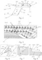
- the Figures 1 - 4 show a signal light or lighting device 10 for a motor vehicle or for a motor vehicle headlight.
- the device 10 comprises a light-guiding body 100 and light sources 50 assigned to it.
- the light-guiding body 100 has a coupling section 110 and a light exit region 160. Via the coupling section 110, light rays emitted by the light sources 50 can be coupled into the light-guiding body 100, where they propagate in the light-guiding body 100 and emerge from the light-guiding body 100 via the light exit region 160.
- the coupling section 110 is designed in such a way, for example in the form of a collimator 111 or several collimators, that the light beams emitted by the at least one light source 50 are essentially aligned in a main fiber optic propagation direction X and are in the direction S1 parallel to the fiber optic main propagation direction X im Light guide body 100 propagate.
- the light sources 50 are preferably arranged in a row, in particular laterally next to one another and transversely to the light guide main propagation direction X.
- the light sources are, for example, each designed as an LED or include at least one LED.
- the light exit area 160 comprises two light exit surfaces 161, 162.
- the light exit surfaces 161, 162 directly adjoin one another and converge in a straight edge.
- a (first) light exit surface 161 lies above the other, second light exit surface 162.
- the two light exit surfaces 161, 162 are inclined to one another at an angle that is preferably greater than 90°, so that a V-shaped arrangement of the two light exit surfaces relative to one another results.
- the upper light exit surface 161 is approximately at the same height as the one or more light sources 50, and preferably the total reflection surface 201 is also approximately at the same height as the at least one light source 50.
- one of the light exit surfaces for example the lower light exit surface 162
- the light-guiding body 100 preferably consists of a transparent solid body, which is formed from a transparent material in which the coupled-in light can propagate.
- the light guide body 100 has a beam splitter device 200, the beam splitter device 200 comprising a total reflection surface 201, which totally reflects at least part of the light rays S1 striking it, so that these totally reflected light rays S3 are reflected in the light guide body 100 in a direction Z deviating from the light guide body.
- Main direction of propagation X especially downwards.
- the total reflection surface 201 has individual optical structures 202, which are designed such that at least a portion of the light rays S1 striking an individual structure 202 emerge from the light guide body 100 via the individual structure 202 and re-enter via a re-entry surface 203 enters the light guide body 100, the re-entered light rays S2 being directed to the first light exit surface 161, which lies opposite the re-entry surface 203, so that these light rays emerge from the first light exit surface 161 in a main radiation direction Y (light rays S4).
- the light exit surface 161 and/or the re-entry surface 203 can have optical structures or elements in order to direct the emerging light S4 in a desired direction (the main emission direction Y).
- the light rays S3 that are totally reflected from the total reflection surface 201 are totally reflected again on a back side 101 of the light guide body 100 and are thereby deflected to the second light exit surface 162 light rays S3 ', where the light rays S5 also emerge from the light guide body 100 in the direction of the main radiation direction Y.
- the second light exit surface 162 can in turn have optical structures in order to emit the light beams S5 in the desired direction and/or to ensure further homogenization of the emitted light.
- a so-called “distinct” straight line g50 can be seen, which lies in a horizontal plane and runs perpendicular to the main light propagation direction X.
- the row of light sources 50 runs parallel to the marked straight line g50.
- the two straight lines g161, g162 now run obliquely to the marked straight line g50 or obliquely to the main light propagation direction X.
- the straight line g201 which results from a horizontal section through the total reflection surface 201, assuming that the total reflection surface 201 is flat, also runs obliquely to the marked straight line g50.
- the straight lines g161, g162, g203 can be arranged parallel to one another, but can also run obliquely to one another.
- the individual structures 202 are arranged uniformly and/or in rows and/or in columns over the total reflection surface 201, as shown in the figures, for example Figure 1 or Figure 5 is easy to see.
- the total reflection surface 201 is divided into several facets 201A, with facets 201A lying laterally next to one another, and with the facets preferably each at an angle greater than 0 ° and less than 90 ° against the light guide main propagation direction X are twisted. Preferably, all facets are rotated by the same angle with respect to the light guide main propagation direction X.
- each facet represents a substantially rectangular, flat surface.
- the normal vector on this surface can be converted into a horizontal component, which is in an im Substantially horizontal plane, which contains the light guide main propagation direction
- the angle mentioned above is the angle that the horizontal component of the normal vector makes to the main light guide propagation direction X.
- the facets lie next to each other in one or more rows one above the other.
- the facets have the advantage over a non-faceted total reflection surface (i.e. with a continuous, flat total reflection surface) that with a second light exit surface running obliquely to the main direction of light guide propagation, the entire total reflection surface would have to be rotated by the said angle, which means that this surface is very large would require installation space. Due to the faceting, it is not necessary to twist a large, continuous surface, but "only" a number/variety of surfaces are twisted, which take up little space due to their significantly smaller extent in the lateral direction compared to a continuous surface take.
- each individual structure 202 is designed as a depression in the total reflection surface 201 or, precisely speaking, as a depression in the light-guiding body 100, starting from the total reflection surface 201.
- Such a depression is, starting from an opening 2021 in the light-guiding body 100 (i.e. in the total reflection surface), delimited by lateral surfaces 2022, 2023, 2024 extending into the light-guiding body 100, one of the lateral surfaces, the so-called base surface 2022, being so is oriented so that light rays S1 striking it pass through the base surface 2022 in the direction of the first light exit surface 161.
- the depressions 202 are "pyramid-shaped", with a triangular opening 2021 and base surface 2022 and the two further lateral surfaces 2023, 2024 which extend into the light-guiding body 100.
- Triangular does not necessarily mean that the connecting lines between two corner points of the “triangle” have to be straight (in this respect it is a “modified” triangle).
- pyramid-shaped means that the shape of the recess is similar but not necessarily identical to a pyramid, for example in that the lateral surfaces are not flat but curved.
- the two further lateral surfaces 2023, 2024 are preferably flat and are aligned essentially parallel to or in the direction of the light beams striking the individual structure 202, i.e. preferably parallel to the main light guide propagation direction X.
- the base surface 2022 in particular into the light guide body 100, is curved.
- a surface normal to the base surface 2022 thus runs essentially parallel to the light guide main propagation direction
- This curvature can (see Figure 7 ) a splitting/expanding effect on an incident light bundle of parallel light rays S1 can be achieved, so that the light rays are evenly distributed on the light exit surface 161 and this shines evenly brightly.
- the depressions 202 are at least partially cylindrical.
- This design of the depressions 202 is advantageous here, since in this variant the excellent straight line g50 and the straight line g161 (see the explanations for these terms in the variant according to Figure 1 ) run parallel to each other ( Figure 9 ) and transverse and normal to the main fiber optic propagation direction X run.
- the lines g161, g162, g201 also run parallel to the marked line g50.
- the depressions are each a "cutout" in the light-guiding body or in the total reflection surface, starting from the total reflection surface 201, with a lateral surface 2022 of the depression being designed in the form of part of a cylinder jacket. This lateral surface or the height of the cylinder jacket runs essentially vertically.
- the incident light rays S1 are directed to the first light exit surface 161 via this lateral surface 2022.
- the lateral surface is preferably curved, in particular curved into the light guide body 100, so that as in the embodiment according to Figure 1 the light rays S1 are "scattered” accordingly (splitting/expanding effect on an incident light bundle of parallel light rays S1), so that the light exit surface 161 is subsequently illuminated more evenly.
- the depression 202 is delimited by three further, preferably flat lateral surfaces 2023, 2024a, 2024b, which "open" into the opening of the depression.
- these surfaces are two lateral lateral surfaces 2024a, 2024b and a bottom lateral surface 2023, which are preferably flat.
- These flat lateral surfaces 2023, 2024a, 2024b preferably extend parallel to the main radiation direction X.
- the opening surfaces lie in the plane of the total reflection surface.
- the total reflection surface can be faceted, i.e. divided into several, preferably flat, facets.
- the opening surfaces lie in the plane of the respective facet, from which the depression extends into the light-guiding body.
- the area A total can be calculated by the sum of the areas of the facets 201A, starting from which areas the depressions 202 extend into the light-guiding body 100.
- the light emitted by the light source or sources is divided according to the ratio of the size of the two light exit surfaces, so that it can be achieved that both light exit surfaces are irradiated with the same light intensity and thus have the same luminance or surface brightness.
Landscapes
- Engineering & Computer Science (AREA)
- General Engineering & Computer Science (AREA)
- Physics & Mathematics (AREA)
- Microelectronics & Electronic Packaging (AREA)
- Optics & Photonics (AREA)
- Non-Portable Lighting Devices Or Systems Thereof (AREA)
- Planar Illumination Modules (AREA)
- Light Guides In General And Applications Therefor (AREA)
Priority Applications (5)
| Application Number | Priority Date | Filing Date | Title |
|---|---|---|---|
| EP22196548.6A EP4343200A1 (fr) | 2022-09-20 | 2022-09-20 | Dispositif d'éclairage ou dispositif d'éclairage pour un phare de véhicule automobile |
| JP2023143855A JP2024045031A (ja) | 2022-09-20 | 2023-09-05 | 自動車投光器用の信号灯装置又は照射装置 |
| KR1020230120920A KR20240040031A (ko) | 2022-09-20 | 2023-09-12 | 자동차 헤드라이트용 신호 발광 장치 또는 조명 장치 |
| US18/369,495 US11971151B2 (en) | 2022-09-20 | 2023-09-18 | Signal lighting device or lighting device for motor vehicle headlamp |
| CN202311208855.9A CN117739299A (zh) | 2022-09-20 | 2023-09-19 | 信号灯装置或照明装置、机动车辆前照灯及机动车辆 |
Applications Claiming Priority (1)
| Application Number | Priority Date | Filing Date | Title |
|---|---|---|---|
| EP22196548.6A EP4343200A1 (fr) | 2022-09-20 | 2022-09-20 | Dispositif d'éclairage ou dispositif d'éclairage pour un phare de véhicule automobile |
Publications (1)
| Publication Number | Publication Date |
|---|---|
| EP4343200A1 true EP4343200A1 (fr) | 2024-03-27 |
Family
ID=83398413
Family Applications (1)
| Application Number | Title | Priority Date | Filing Date |
|---|---|---|---|
| EP22196548.6A Pending EP4343200A1 (fr) | 2022-09-20 | 2022-09-20 | Dispositif d'éclairage ou dispositif d'éclairage pour un phare de véhicule automobile |
Country Status (5)
| Country | Link |
|---|---|
| US (1) | US11971151B2 (fr) |
| EP (1) | EP4343200A1 (fr) |
| JP (1) | JP2024045031A (fr) |
| KR (1) | KR20240040031A (fr) |
| CN (1) | CN117739299A (fr) |
Citations (6)
| Publication number | Priority date | Publication date | Assignee | Title |
|---|---|---|---|---|
| EP2317214A1 (fr) * | 2009-11-02 | 2011-05-04 | Valeo Vision | Dispositif d'éclairage ou de signalisation pour véhicule automobile comprenant un guide de lumière |
| EP2354637A2 (fr) * | 2010-01-30 | 2011-08-10 | Hella KGaA Hueck & Co. | Dispositif d'éclairage pour véhicules |
| WO2017068309A1 (fr) * | 2015-10-23 | 2017-04-27 | Automotive Lighting Rear Lamps France | Dispositif d'éclairage et/ou de signalisation compact pour véhicule |
| EP3330601A1 (fr) * | 2016-11-30 | 2018-06-06 | Automotive Lighting Italia S.p.A. | Feu de véhicule |
| DE102017105838A1 (de) * | 2017-03-17 | 2018-09-20 | Automotive Lighting Reutlingen Gmbh | Beleuchtungseinrichtung eines Kraftfahrzeugs mit einer Lichtleiteranordnung |
| DE102018126955A1 (de) * | 2017-11-01 | 2019-05-02 | Varroc Lighting Systems, s.r.o. | Optisches Lichtleitersystem |
Family Cites Families (3)
| Publication number | Priority date | Publication date | Assignee | Title |
|---|---|---|---|---|
| JP5814302B2 (ja) * | 2013-06-18 | 2015-11-17 | 株式会社小糸製作所 | 車輌用灯具 |
| FR3084755B1 (fr) * | 2018-08-02 | 2020-12-18 | Valeo Vision | Piece optique comprenant un bloc avec un dioptre formant plieuse pour deux faisceaux |
| JP2023155612A (ja) * | 2022-04-11 | 2023-10-23 | スタンレー電気株式会社 | 車両用灯具 |
-
2022
- 2022-09-20 EP EP22196548.6A patent/EP4343200A1/fr active Pending
-
2023
- 2023-09-05 JP JP2023143855A patent/JP2024045031A/ja active Pending
- 2023-09-12 KR KR1020230120920A patent/KR20240040031A/ko unknown
- 2023-09-18 US US18/369,495 patent/US11971151B2/en active Active
- 2023-09-19 CN CN202311208855.9A patent/CN117739299A/zh active Pending
Patent Citations (6)
| Publication number | Priority date | Publication date | Assignee | Title |
|---|---|---|---|---|
| EP2317214A1 (fr) * | 2009-11-02 | 2011-05-04 | Valeo Vision | Dispositif d'éclairage ou de signalisation pour véhicule automobile comprenant un guide de lumière |
| EP2354637A2 (fr) * | 2010-01-30 | 2011-08-10 | Hella KGaA Hueck & Co. | Dispositif d'éclairage pour véhicules |
| WO2017068309A1 (fr) * | 2015-10-23 | 2017-04-27 | Automotive Lighting Rear Lamps France | Dispositif d'éclairage et/ou de signalisation compact pour véhicule |
| EP3330601A1 (fr) * | 2016-11-30 | 2018-06-06 | Automotive Lighting Italia S.p.A. | Feu de véhicule |
| DE102017105838A1 (de) * | 2017-03-17 | 2018-09-20 | Automotive Lighting Reutlingen Gmbh | Beleuchtungseinrichtung eines Kraftfahrzeugs mit einer Lichtleiteranordnung |
| DE102018126955A1 (de) * | 2017-11-01 | 2019-05-02 | Varroc Lighting Systems, s.r.o. | Optisches Lichtleitersystem |
Also Published As
| Publication number | Publication date |
|---|---|
| US20240093853A1 (en) | 2024-03-21 |
| CN117739299A (zh) | 2024-03-22 |
| KR20240040031A (ko) | 2024-03-27 |
| JP2024045031A (ja) | 2024-04-02 |
| US11971151B2 (en) | 2024-04-30 |
Similar Documents
| Publication | Publication Date | Title |
|---|---|---|
| DE60037178T2 (de) | Leuchte, optisches element und verfahren zum beleuchten eines objektes | |
| EP1715244B1 (fr) | Lampe de signalisation pour véhicules | |
| WO2018032025A1 (fr) | Unité d'éclairage pour un projecteur de véhicule automobile, destinée à produire au moins deux distributions de lumière | |
| DE102006008191B4 (de) | Leuchteneinheit für Fahrzeuge | |
| DE102018114099A1 (de) | Lichtleitendes Optiksystem | |
| WO2015049264A1 (fr) | Dispositif d'éclairage destiné à des véhicules | |
| WO2020104311A1 (fr) | Dispositif d'éclairage pour véhicules | |
| EP3531012A1 (fr) | Dispositif d'éclairage pour véhicules automobiles pourvu de guide de lumière allongé | |
| DE69636270T2 (de) | Zonenbildende Lichtverteilungslinse für Fahrzeugscheinwerfer | |
| EP3899358A1 (fr) | Dispositif d'éclairage pour un phare de véhicule automobile ainsi que phare de véhicule automobile | |
| DE102015115969A1 (de) | Beleuchtungsvorrichtung für Fahrzeuge | |
| DE102017115899A1 (de) | Kraftfahrzeugleuchte und Kraftfahrzeugscheinwerfer mit einer solchen Leuchte | |
| EP3861242B1 (fr) | Dispositif d'éclairage pour un phare de véhicule automobile | |
| EP3653926A1 (fr) | Dispositif d'éclairage pour un phare de véhicule automobile ainsi que phare de véhicule automobile | |
| EP3812653A1 (fr) | Feu de signalisation pourvu de guide de lumière | |
| EP3461687B1 (fr) | Dispositif de guide de lumière d'un véhicule automobile et lampe de véhicule automobile muni d'un tel dispositif de guide de lumière | |
| EP4343200A1 (fr) | Dispositif d'éclairage ou dispositif d'éclairage pour un phare de véhicule automobile | |
| DE102019120840A1 (de) | Eine lichtleitende optische Einheit und ein lichtleitendes optisches System, das die lichtleitenden optischen Einheiten umfasst | |
| EP3341648B1 (fr) | Élément optique | |
| DE102018122487A1 (de) | Ein Licht leitendes optisches System, insbesondere für eine Leuchtvorrichtung eines Fahrzeugs | |
| EP3212997B1 (fr) | Élément optique ainsi qu'ensemble d'émission de lumière comprenant un élément optique | |
| EP1106916B1 (fr) | Luminaire comprenant des moyens réfractifs de protection et un réflecteur délimitant le faisceau lumineux | |
| EP1156268B1 (fr) | Lampe à guide de lumière avec structure réfractive non uniforme | |
| DE102022123283B3 (de) | Fahrzeugleuchte | |
| DE102017102237A1 (de) | Beleuchtungsvorrichtung für ein Kraftfahrzeug |
Legal Events
| Date | Code | Title | Description |
|---|---|---|---|
| PUAI | Public reference made under article 153(3) epc to a published international application that has entered the european phase |
Free format text: ORIGINAL CODE: 0009012 |
|
| STAA | Information on the status of an ep patent application or granted ep patent |
Free format text: STATUS: THE APPLICATION HAS BEEN PUBLISHED |
|
| AK | Designated contracting states |
Kind code of ref document: A1 Designated state(s): AL AT BE BG CH CY CZ DE DK EE ES FI FR GB GR HR HU IE IS IT LI LT LU LV MC MK MT NL NO PL PT RO RS SE SI SK SM TR |