EP4342392A2 - Dispositif d'occlusion - Google Patents
Dispositif d'occlusion Download PDFInfo
- Publication number
- EP4342392A2 EP4342392A2 EP24153796.8A EP24153796A EP4342392A2 EP 4342392 A2 EP4342392 A2 EP 4342392A2 EP 24153796 A EP24153796 A EP 24153796A EP 4342392 A2 EP4342392 A2 EP 4342392A2
- Authority
- EP
- European Patent Office
- Prior art keywords
- tissue
- sealing
- apposition
- frame
- petals
- Prior art date
- Legal status (The legal status is an assumption and is not a legal conclusion. Google has not performed a legal analysis and makes no representation as to the accuracy of the status listed.)
- Pending
Links
- 238000007789 sealing Methods 0.000 claims abstract description 422
- 239000000463 material Substances 0.000 claims abstract description 198
- 230000003872 anastomosis Effects 0.000 claims abstract description 93
- 230000007547 defect Effects 0.000 claims abstract description 63
- 230000002093 peripheral effect Effects 0.000 claims description 11
- 230000004308 accommodation Effects 0.000 claims description 2
- 239000012141 concentrate Substances 0.000 claims description 2
- 210000001035 gastrointestinal tract Anatomy 0.000 abstract description 22
- 210000001072 colon Anatomy 0.000 abstract description 11
- 210000001519 tissue Anatomy 0.000 description 168
- 238000000034 method Methods 0.000 description 37
- 210000003484 anatomy Anatomy 0.000 description 18
- 206010052428 Wound Diseases 0.000 description 17
- 208000027418 Wounds and injury Diseases 0.000 description 17
- 230000005012 migration Effects 0.000 description 16
- 238000013508 migration Methods 0.000 description 16
- 238000013461 design Methods 0.000 description 15
- 238000011065 in-situ storage Methods 0.000 description 15
- 239000003566 sealing material Substances 0.000 description 13
- 238000004804 winding Methods 0.000 description 13
- 230000035876 healing Effects 0.000 description 11
- 230000003902 lesion Effects 0.000 description 11
- 230000033001 locomotion Effects 0.000 description 10
- HLXZNVUGXRDIFK-UHFFFAOYSA-N nickel titanium Chemical compound [Ti].[Ti].[Ti].[Ti].[Ti].[Ti].[Ti].[Ti].[Ti].[Ti].[Ti].[Ni].[Ni].[Ni].[Ni].[Ni].[Ni].[Ni].[Ni].[Ni].[Ni].[Ni].[Ni].[Ni].[Ni] HLXZNVUGXRDIFK-UHFFFAOYSA-N 0.000 description 10
- 229910001000 nickel titanium Inorganic materials 0.000 description 10
- 238000012876 topography Methods 0.000 description 10
- 238000011282 treatment Methods 0.000 description 9
- 230000001788 irregular Effects 0.000 description 8
- 230000008569 process Effects 0.000 description 8
- 238000000576 coating method Methods 0.000 description 7
- 210000004379 membrane Anatomy 0.000 description 7
- 239000012528 membrane Substances 0.000 description 7
- 230000002572 peristaltic effect Effects 0.000 description 6
- 238000012546 transfer Methods 0.000 description 6
- 238000012800 visualization Methods 0.000 description 6
- 230000009471 action Effects 0.000 description 5
- 210000000936 intestine Anatomy 0.000 description 5
- 230000000670 limiting effect Effects 0.000 description 5
- 238000002271 resection Methods 0.000 description 5
- -1 ELGILOYTM) Substances 0.000 description 4
- 229910045601 alloy Inorganic materials 0.000 description 4
- 239000000956 alloy Substances 0.000 description 4
- 238000013459 approach Methods 0.000 description 4
- 239000008280 blood Substances 0.000 description 4
- 210000004369 blood Anatomy 0.000 description 4
- 229940088679 drug related substance Drugs 0.000 description 4
- 210000002889 endothelial cell Anatomy 0.000 description 4
- 210000003608 fece Anatomy 0.000 description 4
- 239000012530 fluid Substances 0.000 description 4
- 210000000232 gallbladder Anatomy 0.000 description 4
- 239000007943 implant Substances 0.000 description 4
- 239000000203 mixture Substances 0.000 description 4
- 229910001220 stainless steel Inorganic materials 0.000 description 4
- 238000003466 welding Methods 0.000 description 4
- 206010028980 Neoplasm Diseases 0.000 description 3
- 239000000853 adhesive Substances 0.000 description 3
- 230000001070 adhesive effect Effects 0.000 description 3
- 210000004204 blood vessel Anatomy 0.000 description 3
- 201000011510 cancer Diseases 0.000 description 3
- 239000011248 coating agent Substances 0.000 description 3
- 238000010276 construction Methods 0.000 description 3
- 230000008878 coupling Effects 0.000 description 3
- 238000010168 coupling process Methods 0.000 description 3
- 238000005859 coupling reaction Methods 0.000 description 3
- 238000005520 cutting process Methods 0.000 description 3
- 230000000694 effects Effects 0.000 description 3
- 210000003709 heart valve Anatomy 0.000 description 3
- 239000002243 precursor Substances 0.000 description 3
- 239000007787 solid Substances 0.000 description 3
- 239000010935 stainless steel Substances 0.000 description 3
- 239000000126 substance Substances 0.000 description 3
- 238000001356 surgical procedure Methods 0.000 description 3
- 239000004812 Fluorinated ethylene propylene Substances 0.000 description 2
- 208000007536 Thrombosis Diseases 0.000 description 2
- 238000004873 anchoring Methods 0.000 description 2
- 230000008901 benefit Effects 0.000 description 2
- 239000012620 biological material Substances 0.000 description 2
- 210000005242 cardiac chamber Anatomy 0.000 description 2
- 230000004663 cell proliferation Effects 0.000 description 2
- 230000008859 change Effects 0.000 description 2
- 201000010099 disease Diseases 0.000 description 2
- 208000037265 diseases, disorders, signs and symptoms Diseases 0.000 description 2
- 238000006073 displacement reaction Methods 0.000 description 2
- 239000013013 elastic material Substances 0.000 description 2
- 230000010595 endothelial cell migration Effects 0.000 description 2
- 229920000295 expanded polytetrafluoroethylene Polymers 0.000 description 2
- 238000009998 heat setting Methods 0.000 description 2
- 238000002513 implantation Methods 0.000 description 2
- 210000001503 joint Anatomy 0.000 description 2
- 238000012986 modification Methods 0.000 description 2
- 230000004048 modification Effects 0.000 description 2
- 238000005457 optimization Methods 0.000 description 2
- 230000036961 partial effect Effects 0.000 description 2
- 230000000149 penetrating effect Effects 0.000 description 2
- 229920009441 perflouroethylene propylene Polymers 0.000 description 2
- BASFCYQUMIYNBI-UHFFFAOYSA-N platinum Chemical compound [Pt] BASFCYQUMIYNBI-UHFFFAOYSA-N 0.000 description 2
- 229920000642 polymer Polymers 0.000 description 2
- 229920001343 polytetrafluoroethylene Polymers 0.000 description 2
- 239000004810 polytetrafluoroethylene Substances 0.000 description 2
- 238000000926 separation method Methods 0.000 description 2
- 230000002792 vascular Effects 0.000 description 2
- 206010002329 Aneurysm Diseases 0.000 description 1
- 206010003011 Appendicitis Diseases 0.000 description 1
- 229910000684 Cobalt-chrome Inorganic materials 0.000 description 1
- 208000011231 Crohn disease Diseases 0.000 description 1
- 229920004934 Dacron® Polymers 0.000 description 1
- 208000001750 Endoleak Diseases 0.000 description 1
- JOYRKODLDBILNP-UHFFFAOYSA-N Ethyl urethane Chemical compound CCOC(N)=O JOYRKODLDBILNP-UHFFFAOYSA-N 0.000 description 1
- 206010016717 Fistula Diseases 0.000 description 1
- HTTJABKRGRZYRN-UHFFFAOYSA-N Heparin Chemical compound OC1C(NC(=O)C)C(O)OC(COS(O)(=O)=O)C1OC1C(OS(O)(=O)=O)C(O)C(OC2C(C(OS(O)(=O)=O)C(OC3C(C(O)C(O)C(O3)C(O)=O)OS(O)(=O)=O)C(CO)O2)NS(O)(=O)=O)C(C(O)=O)O1 HTTJABKRGRZYRN-UHFFFAOYSA-N 0.000 description 1
- 206010061218 Inflammation Diseases 0.000 description 1
- 239000004677 Nylon Substances 0.000 description 1
- 208000031481 Pathologic Constriction Diseases 0.000 description 1
- 239000004743 Polypropylene Substances 0.000 description 1
- 229910001260 Pt alloy Inorganic materials 0.000 description 1
- FAPWRFPIFSIZLT-UHFFFAOYSA-M Sodium chloride Chemical compound [Na+].[Cl-] FAPWRFPIFSIZLT-UHFFFAOYSA-M 0.000 description 1
- 229910000831 Steel Inorganic materials 0.000 description 1
- 208000025865 Ulcer Diseases 0.000 description 1
- 229910001080 W alloy Inorganic materials 0.000 description 1
- 239000008186 active pharmaceutical agent Substances 0.000 description 1
- 239000000654 additive Substances 0.000 description 1
- 230000000996 additive effect Effects 0.000 description 1
- 238000004026 adhesive bonding Methods 0.000 description 1
- 229910052782 aluminium Inorganic materials 0.000 description 1
- XAGFODPZIPBFFR-UHFFFAOYSA-N aluminium Chemical compound [Al] XAGFODPZIPBFFR-UHFFFAOYSA-N 0.000 description 1
- 239000003242 anti bacterial agent Substances 0.000 description 1
- 229940088710 antibiotic agent Drugs 0.000 description 1
- 239000003146 anticoagulant agent Substances 0.000 description 1
- 239000003080 antimitotic agent Substances 0.000 description 1
- 229960004676 antithrombotic agent Drugs 0.000 description 1
- 238000010009 beating Methods 0.000 description 1
- 238000005452 bending Methods 0.000 description 1
- 230000009286 beneficial effect Effects 0.000 description 1
- 239000000560 biocompatible material Substances 0.000 description 1
- 229920000249 biocompatible polymer Polymers 0.000 description 1
- 210000001124 body fluid Anatomy 0.000 description 1
- 239000007767 bonding agent Substances 0.000 description 1
- 238000006243 chemical reaction Methods 0.000 description 1
- 238000005253 cladding Methods 0.000 description 1
- 239000010952 cobalt-chrome Substances 0.000 description 1
- 238000002052 colonoscopy Methods 0.000 description 1
- 230000008602 contraction Effects 0.000 description 1
- 229920001577 copolymer Polymers 0.000 description 1
- 239000003246 corticosteroid Substances 0.000 description 1
- 230000006378 damage Effects 0.000 description 1
- 229960002344 dexamethasone sodium phosphate Drugs 0.000 description 1
- PLCQGRYPOISRTQ-FCJDYXGNSA-L dexamethasone sodium phosphate Chemical compound [Na+].[Na+].C1CC2=CC(=O)C=C[C@]2(C)[C@]2(F)[C@@H]1[C@@H]1C[C@@H](C)[C@@](C(=O)COP([O-])([O-])=O)(O)[C@@]1(C)C[C@@H]2O PLCQGRYPOISRTQ-FCJDYXGNSA-L 0.000 description 1
- 239000010432 diamond Substances 0.000 description 1
- 238000003618 dip coating Methods 0.000 description 1
- 208000007784 diverticulitis Diseases 0.000 description 1
- 238000011846 endoscopic investigation Methods 0.000 description 1
- HQQADJVZYDDRJT-UHFFFAOYSA-N ethene;prop-1-ene Chemical group C=C.CC=C HQQADJVZYDDRJT-UHFFFAOYSA-N 0.000 description 1
- 230000003890 fistula Effects 0.000 description 1
- 238000009541 flexible sigmoidoscopy Methods 0.000 description 1
- 229920002313 fluoropolymer Polymers 0.000 description 1
- 239000004811 fluoropolymer Substances 0.000 description 1
- 238000002594 fluoroscopy Methods 0.000 description 1
- 230000006870 function Effects 0.000 description 1
- 239000003102 growth factor Substances 0.000 description 1
- 210000005003 heart tissue Anatomy 0.000 description 1
- 238000010438 heat treatment Methods 0.000 description 1
- 229960002897 heparin Drugs 0.000 description 1
- 229920000669 heparin Polymers 0.000 description 1
- 238000003384 imaging method Methods 0.000 description 1
- 238000001727 in vivo Methods 0.000 description 1
- 208000015181 infectious disease Diseases 0.000 description 1
- 230000004054 inflammatory process Effects 0.000 description 1
- 230000002401 inhibitory effect Effects 0.000 description 1
- 208000014674 injury Diseases 0.000 description 1
- 238000003780 insertion Methods 0.000 description 1
- 230000037431 insertion Effects 0.000 description 1
- 238000009434 installation Methods 0.000 description 1
- 230000003886 intestinal anastomosis Effects 0.000 description 1
- 230000000968 intestinal effect Effects 0.000 description 1
- 238000010030 laminating Methods 0.000 description 1
- 230000007774 longterm Effects 0.000 description 1
- 230000003211 malignant effect Effects 0.000 description 1
- 230000007246 mechanism Effects 0.000 description 1
- 229910001092 metal group alloy Inorganic materials 0.000 description 1
- 239000007769 metal material Substances 0.000 description 1
- 229920001778 nylon Polymers 0.000 description 1
- 210000000056 organ Anatomy 0.000 description 1
- RVTZCBVAJQQJTK-UHFFFAOYSA-N oxygen(2-);zirconium(4+) Chemical compound [O-2].[O-2].[Zr+4] RVTZCBVAJQQJTK-UHFFFAOYSA-N 0.000 description 1
- 210000004303 peritoneum Anatomy 0.000 description 1
- 239000002831 pharmacologic agent Substances 0.000 description 1
- 239000004033 plastic Substances 0.000 description 1
- 238000007747 plating Methods 0.000 description 1
- 229920000728 polyester Polymers 0.000 description 1
- 239000005020 polyethylene terephthalate Substances 0.000 description 1
- 239000002861 polymer material Substances 0.000 description 1
- 229920001155 polypropylene Polymers 0.000 description 1
- 229920001296 polysiloxane Polymers 0.000 description 1
- 239000000843 powder Substances 0.000 description 1
- 230000002829 reductive effect Effects 0.000 description 1
- 230000008439 repair process Effects 0.000 description 1
- 230000004044 response Effects 0.000 description 1
- 238000012216 screening Methods 0.000 description 1
- 239000012781 shape memory material Substances 0.000 description 1
- 229910001285 shape-memory alloy Inorganic materials 0.000 description 1
- 239000011780 sodium chloride Substances 0.000 description 1
- 238000005507 spraying Methods 0.000 description 1
- 239000010959 steel Substances 0.000 description 1
- 210000000130 stem cell Anatomy 0.000 description 1
- 230000000153 supplemental effect Effects 0.000 description 1
- 230000003319 supportive effect Effects 0.000 description 1
- 238000012360 testing method Methods 0.000 description 1
- 230000001225 therapeutic effect Effects 0.000 description 1
- 230000008467 tissue growth Effects 0.000 description 1
- 230000008733 trauma Effects 0.000 description 1
- 230000000472 traumatic effect Effects 0.000 description 1
- 231100000397 ulcer Toxicity 0.000 description 1
Images


Classifications
-
- A—HUMAN NECESSITIES
- A61—MEDICAL OR VETERINARY SCIENCE; HYGIENE
- A61B—DIAGNOSIS; SURGERY; IDENTIFICATION
- A61B17/00—Surgical instruments, devices or methods, e.g. tourniquets
- A61B17/12—Surgical instruments, devices or methods, e.g. tourniquets for ligaturing or otherwise compressing tubular parts of the body, e.g. blood vessels, umbilical cord
- A61B17/12022—Occluding by internal devices, e.g. balloons or releasable wires
-
- A—HUMAN NECESSITIES
- A61—MEDICAL OR VETERINARY SCIENCE; HYGIENE
- A61B—DIAGNOSIS; SURGERY; IDENTIFICATION
- A61B17/00—Surgical instruments, devices or methods, e.g. tourniquets
- A61B17/0057—Implements for plugging an opening in the wall of a hollow or tubular organ, e.g. for sealing a vessel puncture or closing a cardiac septal defect
-
- A—HUMAN NECESSITIES
- A61—MEDICAL OR VETERINARY SCIENCE; HYGIENE
- A61B—DIAGNOSIS; SURGERY; IDENTIFICATION
- A61B17/00—Surgical instruments, devices or methods, e.g. tourniquets
- A61B17/11—Surgical instruments, devices or methods, e.g. tourniquets for performing anastomosis; Buttons for anastomosis
-
- A—HUMAN NECESSITIES
- A61—MEDICAL OR VETERINARY SCIENCE; HYGIENE
- A61B—DIAGNOSIS; SURGERY; IDENTIFICATION
- A61B17/00—Surgical instruments, devices or methods, e.g. tourniquets
- A61B17/12—Surgical instruments, devices or methods, e.g. tourniquets for ligaturing or otherwise compressing tubular parts of the body, e.g. blood vessels, umbilical cord
- A61B17/12022—Occluding by internal devices, e.g. balloons or releasable wires
- A61B17/12027—Type of occlusion
- A61B17/12031—Type of occlusion complete occlusion
-
- A—HUMAN NECESSITIES
- A61—MEDICAL OR VETERINARY SCIENCE; HYGIENE
- A61B—DIAGNOSIS; SURGERY; IDENTIFICATION
- A61B17/00—Surgical instruments, devices or methods, e.g. tourniquets
- A61B17/12—Surgical instruments, devices or methods, e.g. tourniquets for ligaturing or otherwise compressing tubular parts of the body, e.g. blood vessels, umbilical cord
- A61B17/12022—Occluding by internal devices, e.g. balloons or releasable wires
- A61B17/12099—Occluding by internal devices, e.g. balloons or releasable wires characterised by the location of the occluder
-
- A—HUMAN NECESSITIES
- A61—MEDICAL OR VETERINARY SCIENCE; HYGIENE
- A61B—DIAGNOSIS; SURGERY; IDENTIFICATION
- A61B90/00—Instruments, implements or accessories specially adapted for surgery or diagnosis and not covered by any of the groups A61B1/00 - A61B50/00, e.g. for luxation treatment or for protecting wound edges
- A61B90/39—Markers, e.g. radio-opaque or breast lesions markers
-
- A—HUMAN NECESSITIES
- A61—MEDICAL OR VETERINARY SCIENCE; HYGIENE
- A61B—DIAGNOSIS; SURGERY; IDENTIFICATION
- A61B17/00—Surgical instruments, devices or methods, e.g. tourniquets
- A61B17/11—Surgical instruments, devices or methods, e.g. tourniquets for performing anastomosis; Buttons for anastomosis
- A61B17/1114—Surgical instruments, devices or methods, e.g. tourniquets for performing anastomosis; Buttons for anastomosis of the digestive tract, e.g. bowels or oesophagus
-
- A—HUMAN NECESSITIES
- A61—MEDICAL OR VETERINARY SCIENCE; HYGIENE
- A61B—DIAGNOSIS; SURGERY; IDENTIFICATION
- A61B17/00—Surgical instruments, devices or methods, e.g. tourniquets
- A61B17/12—Surgical instruments, devices or methods, e.g. tourniquets for ligaturing or otherwise compressing tubular parts of the body, e.g. blood vessels, umbilical cord
- A61B17/12022—Occluding by internal devices, e.g. balloons or releasable wires
- A61B17/12131—Occluding by internal devices, e.g. balloons or releasable wires characterised by the type of occluding device
- A61B17/1214—Coils or wires
- A61B17/12145—Coils or wires having a pre-set deployed three-dimensional shape
-
- A—HUMAN NECESSITIES
- A61—MEDICAL OR VETERINARY SCIENCE; HYGIENE
- A61B—DIAGNOSIS; SURGERY; IDENTIFICATION
- A61B17/00—Surgical instruments, devices or methods, e.g. tourniquets
- A61B17/0057—Implements for plugging an opening in the wall of a hollow or tubular organ, e.g. for sealing a vessel puncture or closing a cardiac septal defect
- A61B2017/00575—Implements for plugging an opening in the wall of a hollow or tubular organ, e.g. for sealing a vessel puncture or closing a cardiac septal defect for closure at remote site, e.g. closing atrial septum defects
- A61B2017/00592—Elastic or resilient implements
-
- A—HUMAN NECESSITIES
- A61—MEDICAL OR VETERINARY SCIENCE; HYGIENE
- A61B—DIAGNOSIS; SURGERY; IDENTIFICATION
- A61B17/00—Surgical instruments, devices or methods, e.g. tourniquets
- A61B17/0057—Implements for plugging an opening in the wall of a hollow or tubular organ, e.g. for sealing a vessel puncture or closing a cardiac septal defect
- A61B2017/00575—Implements for plugging an opening in the wall of a hollow or tubular organ, e.g. for sealing a vessel puncture or closing a cardiac septal defect for closure at remote site, e.g. closing atrial septum defects
- A61B2017/00597—Implements comprising a membrane
-
- A—HUMAN NECESSITIES
- A61—MEDICAL OR VETERINARY SCIENCE; HYGIENE
- A61B—DIAGNOSIS; SURGERY; IDENTIFICATION
- A61B17/00—Surgical instruments, devices or methods, e.g. tourniquets
- A61B17/0057—Implements for plugging an opening in the wall of a hollow or tubular organ, e.g. for sealing a vessel puncture or closing a cardiac septal defect
- A61B2017/00575—Implements for plugging an opening in the wall of a hollow or tubular organ, e.g. for sealing a vessel puncture or closing a cardiac septal defect for closure at remote site, e.g. closing atrial septum defects
- A61B2017/00615—Implements with an occluder on one side of the opening and holding means therefor on the other
-
- A—HUMAN NECESSITIES
- A61—MEDICAL OR VETERINARY SCIENCE; HYGIENE
- A61B—DIAGNOSIS; SURGERY; IDENTIFICATION
- A61B17/00—Surgical instruments, devices or methods, e.g. tourniquets
- A61B17/0057—Implements for plugging an opening in the wall of a hollow or tubular organ, e.g. for sealing a vessel puncture or closing a cardiac septal defect
- A61B2017/00575—Implements for plugging an opening in the wall of a hollow or tubular organ, e.g. for sealing a vessel puncture or closing a cardiac septal defect for closure at remote site, e.g. closing atrial septum defects
- A61B2017/00623—Introducing or retrieving devices therefor
-
- A—HUMAN NECESSITIES
- A61—MEDICAL OR VETERINARY SCIENCE; HYGIENE
- A61B—DIAGNOSIS; SURGERY; IDENTIFICATION
- A61B17/00—Surgical instruments, devices or methods, e.g. tourniquets
- A61B17/0057—Implements for plugging an opening in the wall of a hollow or tubular organ, e.g. for sealing a vessel puncture or closing a cardiac septal defect
- A61B2017/00575—Implements for plugging an opening in the wall of a hollow or tubular organ, e.g. for sealing a vessel puncture or closing a cardiac septal defect for closure at remote site, e.g. closing atrial septum defects
- A61B2017/00632—Occluding a cavity, i.e. closing a blind opening
-
- A—HUMAN NECESSITIES
- A61—MEDICAL OR VETERINARY SCIENCE; HYGIENE
- A61B—DIAGNOSIS; SURGERY; IDENTIFICATION
- A61B17/00—Surgical instruments, devices or methods, e.g. tourniquets
- A61B17/0057—Implements for plugging an opening in the wall of a hollow or tubular organ, e.g. for sealing a vessel puncture or closing a cardiac septal defect
- A61B2017/00676—Implements for plugging an opening in the wall of a hollow or tubular organ, e.g. for sealing a vessel puncture or closing a cardiac septal defect promotion of self-sealing of the puncture
-
- A—HUMAN NECESSITIES
- A61—MEDICAL OR VETERINARY SCIENCE; HYGIENE
- A61B—DIAGNOSIS; SURGERY; IDENTIFICATION
- A61B17/00—Surgical instruments, devices or methods, e.g. tourniquets
- A61B2017/00743—Type of operation; Specification of treatment sites
- A61B2017/00818—Treatment of the gastro-intestinal system
-
- A—HUMAN NECESSITIES
- A61—MEDICAL OR VETERINARY SCIENCE; HYGIENE
- A61B—DIAGNOSIS; SURGERY; IDENTIFICATION
- A61B17/00—Surgical instruments, devices or methods, e.g. tourniquets
- A61B2017/00831—Material properties
- A61B2017/00867—Material properties shape memory effect
-
- A—HUMAN NECESSITIES
- A61—MEDICAL OR VETERINARY SCIENCE; HYGIENE
- A61B—DIAGNOSIS; SURGERY; IDENTIFICATION
- A61B17/00—Surgical instruments, devices or methods, e.g. tourniquets
- A61B17/11—Surgical instruments, devices or methods, e.g. tourniquets for performing anastomosis; Buttons for anastomosis
- A61B2017/1103—Approximator
-
- A—HUMAN NECESSITIES
- A61—MEDICAL OR VETERINARY SCIENCE; HYGIENE
- A61B—DIAGNOSIS; SURGERY; IDENTIFICATION
- A61B17/00—Surgical instruments, devices or methods, e.g. tourniquets
- A61B17/11—Surgical instruments, devices or methods, e.g. tourniquets for performing anastomosis; Buttons for anastomosis
- A61B2017/1139—Side-to-side connections, e.g. shunt or X-connections
-
- A—HUMAN NECESSITIES
- A61—MEDICAL OR VETERINARY SCIENCE; HYGIENE
- A61B—DIAGNOSIS; SURGERY; IDENTIFICATION
- A61B17/00—Surgical instruments, devices or methods, e.g. tourniquets
- A61B17/12—Surgical instruments, devices or methods, e.g. tourniquets for ligaturing or otherwise compressing tubular parts of the body, e.g. blood vessels, umbilical cord
- A61B17/12022—Occluding by internal devices, e.g. balloons or releasable wires
- A61B2017/1205—Introduction devices
-
- A—HUMAN NECESSITIES
- A61—MEDICAL OR VETERINARY SCIENCE; HYGIENE
- A61B—DIAGNOSIS; SURGERY; IDENTIFICATION
- A61B90/00—Instruments, implements or accessories specially adapted for surgery or diagnosis and not covered by any of the groups A61B1/00 - A61B50/00, e.g. for luxation treatment or for protecting wound edges
- A61B90/39—Markers, e.g. radio-opaque or breast lesions markers
- A61B2090/3966—Radiopaque markers visible in an X-ray image
Definitions
- This disclosure relates generally to implantable medical devices, and more specifically, to implantable medical devices for connecting tissue layers to create an anastomosis and to implantable devices for occluding inhibiting or preventing material movement through tissue apertures, sealing, and allowing healing of defects in tissues
- GI tract lesions of the gastrointestinal (GI) tract can be in the form of polyps that protrude from the mucosal lining with a mushroom-like shape, or flat lesions that are flush on the mucosal lining.
- the need to remove lesions from the mucosal lining of the GI tract is common and growing worldwide.
- the likelihood of having colon lesions increases with age. Approximately half of the people over the age of 60 have at least one colon lesion and often more.
- Some polyps are considered precancerous, which means that while they are not cancer, if left untreated they may develop into cancer.
- GI tract lesions are typically found during cancer screening tests, such as a colonoscopy or flexible sigmoidoscopy.
- Benign and early malignant lesions of the GI tract can usually be removed endoscopically using an electrocautery snare, hot snare, cold snare, or electrocautery knife devices.
- a saline-assisted polypectomy procedure is often used for the removal of large flat lesions in the GI tract.
- lesions become still larger and invasively encompass more than just the mucosal layers of the GI tract, a resection procedure is often performed whereby the full thickness of the wall tissue is removed along with the lesion.
- This procedure is typically performed using laparoscopic or open surgery techniques rather than endoscopically. However, open surgery may not be an option for some patients, and laparoscopic procedures may not allow visualization within the lumen of the conduit being treated.
- An anastomosis is a cross-connection between two tubular tissue structures, such as blood vessels or intestines. For example, when a portion of an intestine is resected, the resulting two ends can be sewn or stapled together (anastomosed), using an intestinal anastomosis procedure. This procedure can restore intestinal continuity after the resection of a bowel portion, or to bypass a portion of unresectable diseased bowel.
- Anastomoses can be created in various manners including, but not limited to: end-to-end, end-to-side, and side-to-side anastomoses. Often, suturing is used to create such anastomoses.
- the medical device includes a frame having single elongate member.
- the elongate member includes (1) a supporting portion configured to conform to a geometry of a first tissue surface and to provide an apposition force against the first tissue surface, (2) an occluding portion configured to conform to a geometry of a second tissue surface and to provide an apposition force against the second tissue surface, and (3) a defect-occupying portion disposed between the supporting portion and the occluding portion.
- the defect-occupying portion is configured to not provide a substantial apposition force against tissue around an aperture of the defect.
- the medical device also includes a sealing material attached to at least a portion of the occluding portion. The sealing material is configured to inhibit material flow through the aperture.
- a second aspect of the invention relates to a medical device for sealing a defect or structure in tissue.
- the medical device includes a wire member that includes a single wound wire.
- the wire includes (a) a sealing member, (2) an apposition member, and (3) a defect-occupying portion disposed between the sealing member and the apposition member.
- the medical device also includes a covering material disposed on at least a portion of the sealing member.
- a third aspect of the invention relates to a medical device system that includes (1) a frame including a single elongate member and (2) a delivery sheath defining a lumen.
- the elongate member forms (1) a supporting portion that is configured to conform to a geometry of a first tissue surface and to provide an apposition force against the first tissue surface, (2) an occluding portion that is configured to conform to a geometry of a second tissue surface and to provide an apposition force against the second tissue surface, (3) a defect-occupying portion disposed between the supporting portion and the occluding portion, and (4) a membrane attached to at least a portion of the occluding portion.
- the membrane is configured to inhibit material flow through the aperture.
- the medical device is configurable in a low-profile configuration such that the medical device can be contained within the lumen. Further, the medical device is configured to expand from the low-profile configuration when the device is liberated from the lumen.
- a fourth aspect of the invention relates to a method of sealing an aperture in a patient's body.
- the method includes inserting an implantable medical device into the aperture using a transcatheter technique.
- the device includes a single wound wire and a covering material.
- the wire forms (1) a sealing member, (2) an apposition member, and (3) a defect-occupying portion disposed between the sealing member and the apposition member.
- the covering material is disposed on at least a portion of the sealing member and is configured to fully overlay the aperture.
- a fifth aspect of the invention relates to an implantable medical device that includes a single elongate member.
- the single elongate member forms (1) a first flange having a plurality of first arms configured about a central axis and forming a circumferential sealing portion at the outer edges of said first flange, (2) a second flange having a plurality of second arms configured about the central axis, and (3) a connecting region interconnecting the first and second flanges and adapted to bridge a defect in a lumen wall.
- the first arms and the second arms have a pre-strained geometry such that an apposition force exists in the presence of the lumen wall and the apposition force does not exist in the absence of said lumen wall.
- a sixth aspect of the invention relates to an implantable medical device that includes a single elongate member.
- the elongate member forms (1) a first flange having a plurality of first arms configured about a central axis and forming a circumferential seal at outer edges of the first flange, (2) a second flange having a plurality of second arms configured about the central axis forming a circumferential sealing portion at outer edges of the second flange, and (3) a connecting region interconnecting the first and second flanges and adapted to cross a defect in a lumen wall.
- the connecting region fluidly connects the first and second flanges.
- the first arms and the second arms have a pre-strained geometry such that an apposition force exists in the presence of the lumen wall and the apposition force does not exist in the absence of the lumen wall.
- a seventh aspect of the invention relates to an implantable medical device that includes a single elongate member.
- the single elongate member forms (1) a first flange having a plurality of first arms configured about a central axis and forming a circumferential sealing portion at the outer edges of the first flange, (2) a second flange having a plurality of second arms configured about the central axis, and (3) a connecting region interconnecting the first and second flanges and adapted to cross a defect in a lumen wall.
- the first arms and the second arms have a pre-strained geometry such that an apposition force exists in the absence of a lumen wall.
- An eighth aspect of the invention relates to an implantable medical device that includes an apposition frame member that forms (1) a first flange having a plurality of first apposition petals configured about a central axis and forming a first circumferential sealing portion, (2) a second flange having a plurality of second apposition petals configured about the central axis and forming a second circumferential sealing portion, and (3) a connecting region connecting the first and second flanges.
- the connecting region defines an aperture along the central axis.
- the implantable medical device also includes a support frame member that forms a plurality of apices and covering material disposed on at least a portion of each of the apposition frame member and the support frame member. In exemplary embodiments, the support frame is disposed concentrically within the aperture.
- Tissues that may be treated include, but are not limited to, those of the GI tract, peritoneum, vascular (arterial or venous) system, cardiac tissues, or the interface between one of these tissues and a synthetic structure such as a patch or vascular graft.
- Defects for which the implantable medical device may be applied include those that may be natural or artificially created, either intentionally or through some traumatic event or disease process. Defects may include, but are not limited to, perforations, ruptures, wounds, tears, endoleaks, fistulae, and the like.
- this disclosure provides, inter alia , implantable devices for connecting tissue layers, such as for connecting a gallbladder and a portion of a gastrointestinal tract to create an anastomosis that facilitates material flow therebetween.
- the devices are endoscopically deployable or deployable via a catheter and can include self-expanding apposition mechanisms that facilitate a secure connection between the tissue structures (such a connection may also be referred to herein as a "shunt,” “passageway,” “shunt passageway,” or “tunnel”).
- shunt bypass
- bypass passageway bypass passageway
- the devices provided herein allow treatment to circumvent a conduit or organ blockage by creating a direct passage between tissue structures, such as, for example, the gallbladder and a portion of the gastrointestinal tract.
- the devices provided herein are implanted temporarily. As one example, the device is implanted and remains in place until the gallbladder and/or its associated ducts are cleared of blockages, after which the device is removed. In another example, the device remains implanted until the body grows a tissue-anastomosis around the device, and then the device is removed. In other embodiments, tissue ingrowth into and/or around the device permanently implants the device, and the device is not removed.
- Such devices can provide an alternative treatment for patients who are not suitable candidates for other types of treatment (e.g., gallbladder removal surgery) and/or to avoid known complications of other types of treatment (e.g., external biliary drainage).
- a frame 100 of an exemplary tissue-sealing device includes an elongate member 110.
- the elongate member 110 is configured to form an apposition portion 120, a sealing portion 130, and a defect-occupying portion 140.
- the defect-occupying portion 140 is disposed between the apposition portion 120 and the sealing portion 130.
- the defect-occupying portion 140 is configured to traverse an opening or aperture in one or more layers of tissue, also referred to herein as a tissue defect.
- the apposition portion 120 and the sealing portion 130 are configured to be on opposite sides of the layer(s) of tissue.
- the elongate member 110 comprises a single continuous wire.
- the elongate member 110 can comprise a variety of materials.
- the elongate member 110 may be elastomeric, metallic, a spring wire, a shape memory alloy wire, a super-elastic alloy wire, or combinations thereof, to name a few general examples.
- any type of elongate member 110 that is suitably biocompatible, flexible, and resilient can generally be used for the tissue-sealing devices provided herein.
- the elongate member 110 can comprise nitinol (NiTi), L605 steel, stainless steel, polymeric materials, or any other appropriate biocompatible material, including combinations of materials.
- bioresorbable or bioabsorbable materials may be used, including, for example, a bioresorbable or bioabsorbable polymer.
- the elongate member 110, or portions thereof, may eventually dissolve.
- the elongate member 110 is fully or partially coated to stimulate a biological reaction, such as, but not limited to, endothelial cell attachment, endothelial cell migration, endothelial cell proliferation, and resistance to or promotion of thrombosis.
- suitable materials for the elongate member 110 include a variety of metallic shape memory materials and super-elastic alloys.
- Shape memory refers to the ability of a material to revert or substantially revert to an originally memorized shape after plastic deformation by heating above a critical temperature.
- Super-elasticity refers to the ability of a material to deform under strain to a very large degree, without having this deformation become permanent.
- the super-elastic materials included in the frames of some tissue-sealing device embodiments provided herein are able to withstand a significant amount of bending and flexing and then return to the frame's original form (or approximately thereto) without deformation.
- suitable shape memory and super-elastic materials include various stainless steels which have been physically, chemically, and otherwise treated to produce high springiness, metal alloys such as cobalt chrome alloys (e.g., ELGILOYTM), platinum/tungsten alloys, and the NiTi alloys.
- metal alloys such as cobalt chrome alloys (e.g., ELGILOYTM), platinum/tungsten alloys, and the NiTi alloys.
- NiTi elongate members 110 can be shape-set into a desired shape such that the NiTi elongate member 110 will tend to self-expand from a low-profile delivery configuration into the desired shape when deployed from a delivery sheath to a target site within a body.
- the elongate member 110 can be treated in various ways to increase the radiopacity of the elongate member 110 for enhanced radiographic visualization.
- the elongate member 110 is at least partially a drawn-filled type of NiTi containing a different material at the core, such as a material with enhanced radiopacity.
- the elongate member 110 has a radiopaque cladding or plating on at least portions of the elongate member 110.
- one or more radiopaque markers are attached to the elongate member 110 (and/or to a covering material that is attached to the elongate member 110).
- the diameter or thickness of the elongate member 110 is within a range of about 0.1 mm to about 1.50 mm, but in some embodiments an elongate member 110 having smaller or larger diameters can be used. In some embodiments, the diameter of thickness of the elongate member 110 is within a range of about 0.2 mm to about 0.5 mm. Notwithstanding, it it is to be appreciated that the elongate member 110, and the elongate members of other tissue-sealing devices provided herein, can have any suitable size or diameter.
- the elongate member 110 has a consistent diameter along the length of the elongate member 110. In some embodiments, one or more portions of the elongate member 110 are diametrically tapered or otherwise inconsistent in diameter. In some embodiments, the elongate member 110 may be formed using a center-less grinding technique, such that the diameter of the wire varies along the length of the elongate member 110. The elongate member 110 may have a round cross-sectional shape or may have a cross-sectional shape that is not round, such as a rectangle or other polygon.
- Examples of other cross-sectional shapes that the elongate member 110 may have include a square, oval, rectangle, triangle, D-shape, trapezoid, or irregular cross-sectional shape formed by a braided or stranded construct.
- the elongate member 110 may comprise a flat wire.
- a combination of such various types of elongate member 110 are used in a tissue-sealing device. While in some embodiments the elongate member 110 of the device has a uniform cross-sectional shape and size, in some embodiments, some portions of the elongate member 110 have a different cross-sectional shape and/or size than other portions of the elongate member 110.
- the elongate member 110 of the tissue-sealing devices provided herein may exhibit, for example, beneficial fatigue resistance and elastic properties.
- the elongate member 110 allows the tissue-sealing devices to be elastically crushed, folded, and/or collapsed into a low-profile delivery configuration for containment within a lumen for transcatheter or endoscopic/thorascopic delivery, and to self-expand to an operative size and configuration once positioned at a desired target site within a body and deployed from the lumen.
- the elongate member 110 of the frame 100 (and the elongate members of the other frames described herein) can be over-distended without incurring damage to the frame 100.
- the elongate member 110 is capable of being deformed, such as when an oversized device is placed through the frame 100, and the elongate member 110 will return (or substantially return) to its pre-deformed configuration without sustaining permanent deformation such as wrinkling or folding.
- the elongate member 110 may include one or more fixation elements (e.g., anchors, barbs, protrusions, atraumatic members, and/or penetrating members, and combinations thereof).
- fixation elements e.g., anchors, barbs, protrusions, atraumatic members, and/or penetrating members, and combinations thereof.
- fixation elements advantageously reduce or inhibit in situ migration of the tissue-sealing devices after deployment to a target site within a body.
- the apposition portion 120 (also referred to herein as the supporting portion or apposition member) includes multiple features that are configured to contact a surface of a tissue around a defect in the tissue, and to provide an apposition force to the tissue surface.
- the one or more features of the apposition portion 120 include elongate wire loops 122 (also referred to herein as "fingers" or "petals").
- the apposition portion 120 includes eight wire loops 122, more or fewer than eight wire loops 122 may be included.
- one, two, three, four, five, six, seven, nine, ten, eleven, twelve, or more than twelve wire loops 122 may be included in the apposition portion 120.
- the wire loops 122 of the apposition portion 120 are depicted as being generally ovular in shape; however, it should be understood that an ovular shape is not required.
- the wire loops 122 can be circular, triangular, linear, rectangular, diamond-shaped, and the like, or combinations thereof.
- the wire loops 122 can have a first linear portion that projects radially from the defect-occupying portion 140 and that is contiguous with a second diamond-shaped portion at the free end of the wire loops 122.
- the shape and size of all of the individual wire loops 122 is generally uniform, such uniformity is not a requirement.
- one or more of the wire loops 122 may be shaped or sized differently from one or more other wire loops 122 of the same tissue-sealing device.
- the wire loops 122 are configured to independently bear loads associated with tissue surface contact. That is, individual ones of the wire loops 122 can be independently deflected in accordance with the topography of the tissue surface without imparting a substantial force to any other ones of the wire loops 122. This feature can allow each of the wire loops 122 to provide an appositional force even though the tissue surface topography is not planar.
- the apposition portion 120 is configured to be highly conformable to irregular tissue surfaces (refer, e.g., to FIG. 13C).
- portions of individual wire loops 122 may overlap with adjacent wire loops 122. In some such embodiments, some movements of the wire loops 122 may induce forces on adjacent wire loops 122.
- the elongate member 110 also forms the sealing portion 130 (also referred to herein as the "occluding portion,” “central portion,” or “sealing member”).
- a generally fluid impermeable covering material may be disposed on the sealing portion 130.
- the sealing portion 130 includes one or more features that are configured to contact a surface of a tissue around a defect in the tissue, and to provide an apposition force to the tissue surface.
- the one or more features of the sealing portion 130 include elongate wire loops. Although eight wire loops 132 are shown, it is to be appreciated that more or fewer that eight wire loops 132 may be included.
- one, two, three, four, five, six, seven, nine, ten, eleven, twelve, or more than twelve wire loops 132 may be included in the apposition portion 130.
- the number of wire loops 122 of the apposition portion 120 may be unequal to the number of wire loops 132 of the sealing portion 130.
- the shape of the wire loops 122 of the apposition portion 120 may be different than the shape of the wire loops 132 of the sealing portion 130.
- the wire loops 132 of the sealing portion 130 are having a generally ovular shape, it should be understood that the ovular shape is not required.
- the wire loops 132 can be circular, triangular, linear, rectangular, diamond-shaped, and the like, and combinations thereof.
- the wire loops 132 can have a first linear portion that projects radially from the defect-occupying portion 140, and a second diamond-shaped portion at the free end of the wire loops 132.
- Other combinations and shapes are also envisioned and are considered to be within the purview of the invention.
- each of the wire loops 132 generally uniform. However, it should be understood that such uniformity is not a requirement. For example, in some embodiments one or more of the wire loops 132 are shaped or sized differently from one or more other wire loops 132.
- the wire loops 132 are configured to independently bear loads associated with tissue surface contact. That is, individual ones of the wire loops 132 can be independently deflected in accordance with the topography of the tissue surface without imparting a substantial force to any other ones of the wire loops 132. This feature can allow each of the wire loops 132 to provide an appositional force even though the tissue surface topography is non-planar.
- the sealing portion 130 is configured to be highly conformable to irregular tissue surfaces (refer, e.g., to FIG. 13D).
- portions individual wire loops 132 may overlap with adjacent wire loops 132. In some such embodiments, some movements of the wire loops 132 may induce forces on adjacent wire loops 132.
- At least portions of the wire loops 132 are configured to overlap with each other. That is, at least portions of individual ones of the wire loops 132 can overlap with at least portions of the other wire loops 132 that are adjacent thereto. In some embodiments, such overlap may enhance the sealing capabilities of the sealing portion 130.
- the apposition portion 120 and the sealing portion 130 each define a generally circular circumference around their peripheries, a circular shape is not required in all embodiments.
- the periphery of either of the apposition portion 120 or the sealing portion 130 (or both) can define other shapes such as, but not limited to, an ellipse, rectangular, triangular, and other geometric or regular or irregular shapes.
- the wire loops 122 of the apposition portion 120 and corresponding wire loops 132 of the sealing portion 130 are not parallel.
- the distance between the free ends of the wire loops 122 and 132 is less than the distance between the wire loops 122 and 132 near the defect-occupying portion 140 (e.g., as shown in FIG. 1B ).
- Such a configuration provides an increased level of apposition force at the outer radius of the frame 100 as compared to the apposition force nearer to the defect-occupying portion 140.
- the increased level of apposition force at the outer radius of the frame 100 can, in turn, facilitate conformance by the frame 100 to a significantly non-planar and irregular tissue surface.
- the distance between the free ends of the wire loops 122 and 132 can be reduced to essentially zero.
- the wire loops 122 and 132 can cross over each other (e.g., refer to FIG. 10 ).
- the elongate member 110 (and the elongate members of some embodiments of the other devices described herein) is a single continuous element. Accordingly, the elongate member 110 includes two free ends or termini. In some embodiments, the two free ends of the elongate member 110 can be conjoined such that the elongate member 110 forms a closed wind pattern (i.e., a continuous loop). The free ends of the elongate member 110 can be joined together using a variety of techniques including, but not limited to bonding, welding (e.g., laser welding), gluing, using a sleeve coupling, and the like, and combinations thereof.
- welding e.g., laser welding
- a butt joint is used to join the free ends of the elongate member 110.
- other types of joints can be used to join the free ends of the elongate member 110, including but not limited to, an overlap joint, a twist joint, a crimp joint, and the like, and combinations thereof.
- the free ends can be conjoined prior to or after heat-setting (in those embodiments that use a heat-setting process). In some embodiments, the free ends are not conjoined.
- a covering material 210 (also referred to herein as a sealing material or a membrane) can be disposed on or around and/or attached to at least a portion of the sealing portion 130.
- the covering material 210 is attached to the sealing portion 130 of the frame 100 to create the tissue-sealing device 200.
- the tissue-sealing device 200 is shown sealing a large tissue aperture 230 in FIG. 2A
- the same tissue-sealing device 200 is shown sealing a smaller tissue aperture 270 in FIG. 2B .
- tissue defects 230 and 270 can result from a number of causes, such as a resection to remove a lesion, a burst aneurysm, a trauma-induced hole or tear, a fistula, diseases such as appendicitis or diverticulitis, Crohn's disease, and ulcers, to provide a few non-limiting examples.
- Figures 2A and 2B illustrate how the design of the tissue-sealing device 200 advantageously lends itself to sealing a wide variety of differently-sized and shaped apertures 230 and 270. This is accomplished, at least in part, because the defect-occupying portion 140 is configured to exert a low level of radial force to the perimeter tissue of the tissue apertures 230 and 270. Additionally, the appositional force that provides sealing and migration resistance is substantially delivered by the apposition portion 120 and the sealing portion 130, rather than the defect-occupying portion 140.
- the appositional forces provided by the apposition portion 120 and the sealing portion 130 are substantially independent of the in situ device shape or diameter, thus providing reliable sealing across a wide variety of anatomies, and for dynamic anatomies (e.g., such as the GI tract).
- the tissue-sealing device 200 may be configured to be implanted in a patient such that the covering material 210 fully overlays and seals the tissue apertures 230 and 270.
- the covering material 210 may be disposed on the sealing portion 130, but not on the apposition portion 120, nor the defect-occupying portion 140.
- the covering material 210 may be disposed on all or portions of the apposition portion 120 and/or the defect-occupying portion 140 in addition to the sealing portion 130.
- tissue-sealing device 200 is used to occlude/seal a defect in the wall of a body lumen such as an intestine or blood vessel.
- tissue-sealing device 200 is deployed so that the sealing portion 130 with the covering material 210 is positioned on the inside of the body lumen.
- materials that are contained within the body lumen are occluded, i.e., prevented from leaking from the body lumen.
- the tissue-sealing device 200 provides separation of intralumenal materials from the defect. The separation can, in some scenarios, allow healing of the defect, because contact of the biomaterials to the defect may tend to inhibit or prevent the healing process of the tissue surrounding the defect.
- tissue-sealing device 200 can be temporarily implanted in the colon such that the covering material 210 overlays the perforation of the colon wall.
- the perforation will be sealed by the tissue-sealing device 200 such that fecal matter will not escape from the colon to contaminate other portions of the body, and the tissue surrounding the perforation will be isolated from fecal matter so that the tissue's healing process will not be inhibited.
- the tissue-sealing device 200, or portions thereof can be removed from the patient.
- tissue-sealing device 200, or portions thereof may be naturally expelled by the body.
- the tissue-sealing device 200 may be implanted permanently.
- portions of the tissue-sealing device 200 are retrievable while other portions will remain at the defect site.
- portions of the covering material 210 can provide a scaffold for tissue ingrowth or endothelialization to allow healing of the defect. Then, those portions of the covering material 210 can be made to separate from the tissue-sealing device 200 and stay at the defect site when the other parts of the tissue-sealing device 200 are retrieved from the patient's body.
- the tissue-sealing device 200, or portions thereof are bioabsorbable such that the structure of the tissue-sealing device 200 will deteriorate in time.
- portions of the elongate member 110 may deteriorate by bioabsorption, after which other portions of the tissue-sealing device 200 may be naturally expelled from the GI tract, or otherwise retrieved.
- the elongate member 110 may need to be severed in one or more locations prior to removal from the body. That may the case, for example, when tissue growth has engulfed portions of the elongate member 110.
- the covering material 210 is made of a membranous material that inhibits or reduces passage of blood, and other bodily fluids and substances.
- the covering material 210 has a material composition and configuration that inhibits or prevents endothelialization and tissue ingrowth to the covering material 210. Such a feature may be advantageous, for example, for scenarios in which the tissue-sealing device 200 is intended to be implanted temporarily in a patient and then retrieved from the patient.
- the covering material 210 has a microporous structure that promotes endothelialization and/or provides a tissue ingrowth scaffold for durable sealing and/or supplemental anchoring strength of the sealing device.
- a tissue ingrowth scaffold for durable sealing and/or supplemental anchoring strength of the sealing device.
- the covering material 210 comprises a fluoropolymer, such as an expanded polytetrafluoroethylene (ePTFE) polymer.
- ePTFE expanded polytetrafluoroethylene
- the covering material 210 comprises a polyester, a silicone, a urethane, other biocompatible polymer(s), Dacron, bioabsorbable systems, copolymers, or combinations thereof.
- the covering material 210, or portions thereof, used in the tissue-sealing device 200 and other tissue-sealing device embodiments is modified by one or more chemical or physical processes that enhance one or more properties of the materials.
- a hydrophilic coating may be applied to the covering material 210 to improve the wettability and echo translucency of the material 210.
- the covering material 210, or portions thereof may be modified with chemical moieties that promote one or more of endothelial cell attachment, endothelial cell migration, endothelial cell proliferation, and resistance to or promotion of thrombosis.
- the covering material 210 may be modified with one or more covalently attached drug substances (e.g., heparin, antibiotics, and the like) or impregnated with the one or more drug substances.
- the drug substances can be released in situ to promote healing, reduce tissue inflammation, reduce or inhibit infections, and to promote various other therapeutic treatments and outcomes.
- the drug substance is a corticosteroid, a human growth factor, an anti-mitotic agent, an antithrombotic agent, a stem cell material, or dexamethasone sodium phosphate, to name some examples.
- a pharmacological agent is delivered separately from the covering material 210 to the target site to promote healing of the tissue defect.
- Coatings and treatments may be applied to the covering material 210 before or after the covering material 210 is joined or disposed on the frame 100 of the tissue-sealing device 200. Additionally, one or both sides of the covering material 210, or portions thereof, may be coated. In some embodiments, certain coatings and/or treatments are applied to the material(s) located on some portions of the tissue-sealing device 200, and other coatings and/or treatments are applied to the material(s) located on other portions of the tissue-sealing device 200. In some embodiments, a combination of multiple coatings and/or treatments are applied to the covering material 210, or portions thereof. In some embodiments, certain portions of the tissue-sealing device 200 are left uncoated and/or untreated.
- a first portion of the covering material 210 is formed of a first material and a second portion of the covering material 210 is formed of a second material.
- the covering material 210 is comprised of multiple layers of materials, which may be the same or different materials.
- portions of the covering material 210 have one or more radiopaque markers attached thereto to enhance in vivo radiographic visualization of the tissue-sealing device 200.
- the covering material 210 is attached to the elongate member 110 of the sealing portion 130.
- the attachment can be accomplished by a variety of techniques, such as by stitching the covering material 210 to the sealing portion 130, by adhering the covering material 210 to the sealing portion 130, by laminating multiple layers of the covering material 210 to encompass the sealing portion 130, by using clips or barbs, or by other such techniques or combinations thereof.
- the elongate member 110 of the sealing portion 130, or portions thereof may be coated with a bonding agent, for example fluorinated ethylene propylene (FEP) or other suitable adhesive for bonding the covering material 210 to the sealing portion 130.
- FEP fluorinated ethylene propylene
- the adhesive may be applied through contact coating, powder coating, dip coating, spray coating, or any other appropriate means.
- the sealing portion 130 thereby provides a supportive structural framework for the covering material 210 that may be otherwise relatively flaccid.
- the design of the tissue-sealing device 200 facilitates a durable ongoing seal of a defect in a body lumen wall, notwithstanding the fact that some anatomical environments in which the tissue-sealing device 200 may be used are dynamic, such as the dynamic peristaltic motion environment of the GI tract.
- the tissue-sealing device 200 includes design features that facilitate the seal even in such dynamic environments.
- the tissue-sealing device 200 is highly flexible and therefore highly conformable to irregular tissue topography.
- the apposition forces provided by the apposition portion 120 and the sealing portion 130 are substantially independent of the in situ device shape and/or diameter.
- one or more auxiliary tissue anchorage features are included on the elongate member 110.
- Such anchorage features can provide increased fixation and to resistance to migration of the tissue-sealing device 200 within the body.
- tissue-sealing device 200 (and other tissue-sealing device embodiments and anastomosis device embodiments provided herein), as well as the flexibility and elasticity of the elongate member 110, make the tissue-sealing device 200 capable of transcatheter deployment. That is, in some embodiments the tissue-sealing device 200 can be elastically collapsed to a low-profile configuration for temporary containment within a lumen of a delivery catheter or sheath.
- the sheath containing the tissue-sealing device 200 in the low-profile configuration is inserted into the body of a patient and directed to a target site-typically using radiographic visualization (e.g., fluoroscopy), or using endoscopic optics for direct visualization.
- the tissue-sealing device 200 is caused to emerge and become liberated from the sheath (e.g., using a pusher catheter), after which the tissue-sealing device 200 self-expands, or is caused to expand, to an enlarged configuration.
- FIGS. 1A and 1B show the frame 100 of the tissue-sealing device 200 in the enlarged configuration that the frame 100 will naturally tend to seek in the absence of external constraining forces, such as those forces from a delivery sheath.
- tissue-sealing device 200 when the tissue-sealing device 200 (and the other devices described herein) is deployed in a patient's body, there will typically be constraining forces applied to the tissue-sealing device 200, such as from the tissue and tissue aperture in which the tissue-sealing device 200 resides. Because of those constraining forces, the shape of the tissue-sealing device 200 within the body may tend to be different than the shapes shown in the figures of the instant disclosure. Said another way, when the tissue-sealing device 200 is deployed within the body, the tissue-sealing device 200 will try to expand to its natural fully enlarged configuration, but the tissue-sealing device 200 may be constrained by the contours of the anatomy at the target site. In such circumstances, the shape of the tissue-sealing device 200 will tend to conform to the contours of the anatomy.
- the contours of the anatomy may change over time. For example, if the tissue-sealing device 200 is deployed within the GI tract, the peristaltic wave motion of the intestines may change the contours of the anatomy at the target site. In that circumstance, the flexibility and elasticity of the tissue-sealing device 200 can allow the elongate member 110 to adapt in shape to thereby facilitate resilient ongoing contact between the covering material 210 and the tissue surrounding the tissue defect.
- a frame 400 of another exemplary tissue-sealing device includes an elongate member 410.
- the elongate member 410 forms an apposition portion 420, a sealing portion 430, and a defect-occupying portion 440.
- the defect-occupying portion 440 is disposed between the apposition portion 420 and the sealing portion 430.
- the defect-occupying portion 440 is configured to traverse an opening or aperture in one or more layers of tissue.
- the apposition portion 420 and the sealing portion 430 are configured to be on opposite sides of the layer(s) of tissue.
- the elongate member 410 comprises a single continuous wire that was formed to define the frame 400.
- the elongate member 410 defines apposition petals 422 that comprise the apposition portion 420, and sealing petals 432 that comprise the sealing portion 430.
- the apposition petals 422 and the sealing petals 432 are shaped essentially as triangles. In some embodiments, a variety of different shapes and/or combinations of different shapes can be used for the petals 422 and 432.
- the frame 400 can share many of the same features and characteristics as described above in reference to frame 100. However, one difference (in addition to the shape of the petals 422 and 432 as previously described) is that the wind pattern of the elongate member 410 results in a partial overlap of adjacent petals 422 and 432. To be clear, the elongate member 410 is formed so that an individual apposition petal 422 partially overlaps with its adjacent apposition petals 422 on both sides of the individual apposition petal 422. Similarly, the elongate member 410 is formed so that an individual sealing petal 432 partially overlaps with the adjacent sealing petals 432 on both sides of the individual sealing petal 432. Such overlap of the adjacent sealing petals 432 can provide enhanced sealing performance in some embodiments.
- a frame of a tissue-sealing device can include an apposition portion comprised of the wire loops 122 of the frame 100 (referring to FIGS. 1A and 1B ) and a sealing portion comprised of the sealing petals 432 of the frame 400. All combinations of shapes, sizes, patterns, components, features, etc. of one tissue-sealing device embodiment can be combined with all other shapes, sizes, patterns, components, features, etc. of all other tissue-sealing device embodiments described herein to create numerous iterations of hybrid tissue-sealing devices in addition to the individual embodiments described herein.
- a covering material 510 can be disposed on or around and/or attached to at least a portion of the elongate member 410 that includes the sealing portion 430.
- the covering material 510 may be attached to sealing petals 432 of the sealing portion 430 to create an example tissue-sealing device 500.
- the tissue-sealing device 500 is shown in FIG. 5 as sealing a tissue aperture 530.
- the covering material 510 can be a material as described above in reference to covering material 210.
- the covering material 510 can be attached to the elongate member 410 as described above in reference to the attachment of covering material 210 to elongate member 110.
- tissue aperture 530 is depicted as generally circular, it should be understood that the design of the tissue-sealing device 500 (and other tissue-sealing device embodiments described herein) advantageously lends itself to sealing a wide variety of differently-sized and shaped apertures 530. That is accomplished in part because the defect-occupying portion 440 is configured to exert a low level of radial force to the tissue aperture 530. Additionally, the appositional force for sealing and migration resistance is substantially delivered by the apposition portion 420 and the sealing portion 430, rather than the defect-occupying portion 440.
- the appositional forces delivered by the apposition portion 420 and the sealing portion 430 are substantially independent of the in situ device shape or diameter, thus providing reliable sealing across a wide variety of anatomies, and for dynamic anatomies (e.g., such as the GI tract).
- the tissue-sealing device 500 is configured to be implanted in a patient such that the covering material 510 fully overlays and seals the tissue aperture 530.
- the covering material 510 is disposed on the sealing portion 430, but not on the apposition portion 420, nor the defect-occupying portion 440.
- the covering material 510 may be disposed on all or portions of the apposition portion 420 and/or the defect-occupying portion 440 in addition to the sealing portion 430.
- the elongate member 410 can be wound into the aforementioned shape to create frame 400 using a winding mandrel.
- the assembly can be heated to induce a memory shape in the elongate member 410 corresponding to the shape of the frame 400 as-wound on the mandrel.
- the two free ends of the elongate member 410 can be conjoined as described above.
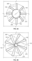
- another exemplary tissue-sealing device 800 includes a frame 700 and a covering material 810 is illustrated.
- the covering material 810 is disposed on at least on a sealing portion 730 of the frame 700.
- the tissue-sealing device 800 is shown sealing an exemplary tissue aperture 830.
- the elongate member 710 forms the frame 700 that includes an apposition portion 720, a sealing portion 730, and a defect-occupying portion 740.
- the apposition portion 720 and the sealing portion 730 are mirror images of each other. However, such mirror imagery is not required. Thus, in some embodiments, the apposition portion 720 and the sealing portion 730 are configured dissimilarly.
- the defect-occupying portion 740 is disposed between the apposition portion 720 and the sealing portion 730. Additionally, the defect-occupying portion 740 is configured to traverse the defect or aperture 830 in one or more layers of tissue.
- the apposition portion 720 and the sealing portion 730 are configured to be on opposite sides of the layer(s) of tissue.
- the elongate member 710 includes a single continuous wire that has beem bent to form the frame 700.
- the elongate member 710 defines apposition petals 722 that form the apposition portion 720, and sealing petals 732 that form the sealing portion 730.
- the apposition petals 722 and the sealing petals 732 are shaped essentially as trapezoids. In other embodiments, different shapes and combinations of different shapes can be used for the petals 722 and 732.
- the frame 700 can share many of the same features and characteristics as described above in reference to frames 100 and 400. However, one difference (in addition to the shape of the petals 722 and 732) is that the wind pattern of the elongate member 710 results in a peripheral frame 724. To be clear, the elongate member 710 is wound so that combined portions of the elongate member 710 define an apposition portion peripheral frame 724. Similarly, the elongate member 710 is wound so that combined portions of the elongate member 710 define a sealing portion peripheral frame 734. Having a sealing portion peripheral frame 734 can provide enhanced sealing performance in some embodiments.
- a frame of a tissue-sealing device may include an apposition portion including the wire loops 122 of the frame 100 (referring to FIGS. 1A and 1B ), a sealing portion comprised of the sealing petals 732, and the sealing portion peripheral frame 734 of the frame 700. It is to be appreciated that all combinations of shapes, sizes, patterns, components, features, etc. of one tissue-sealing device embodiment can be combined with any other shapes, sizes, patterns, components, features, etc. of all other tissue-sealing device embodiments to create numerous iterations of hybrid tissue-sealing devices in addition to the individual embodiments described herein.
- the covering material 810 may be a material as described above in reference to covering material 210.
- the covering material 810 can be attached to or disposed on the elongate member 710 as described above in reference to the attachment of covering material 210 to elongate member 110.
- tissue aperture 830 is depicted as generally circular, it should be understood that the design of the tissue-sealing device 800 (and other embodiments described herein) advantageously lends itself to sealing a wide variety of differently-sized and shaped apertures 830. This is accomplished in part because the defect-occupying portion 740 is configured to exert a low level of radial force to the tissue aperture 830. Additionally, the appositional force for sealing and migration resistance is substantially provided by the apposition portion 720 and the sealing portion 730, rather than the defect-occupying portion 740.
- the appositional forces provided by the apposition portion 720 and the sealing portion 730 are substantially independent of the in situ device shape or diameter, thus providing reliable sealing across a wide variety of anatomies, and for dynamic anatomies (e.g., such as the GI tract).
- the tissue-sealing device 800 is configured to be implanted in a patient such that the covering material 810 fully overlays and seals the tissue aperture 830.
- the covering material 810 is disposed on the sealing portion 730, but not on the apposition portion 720, nor the defect-occupying portion 740.
- the covering material 810 can be disposed on all or portions of the apposition portion 720 and/or the defect-occupying portion 740 in addition to the sealing portion 730.
- the elongate member 710 may be wound into the aforementioned shape to create frame 700 using a winding mandrel. After winding the elongate member 710 on the mandrel, the assembly can be heated to induce a memory shape in the elongate member 710 corresponding to the shape of the frame 700 as-wound on the mandrel. Also, the two free ends of the elongate member 710 can be conjoined as described above.
- FIGS. 10 , 11A -11C, and 12A-12D another exemplary tissue-sealing device 1100 includes a frame 1000 and a covering material 1110.
- the covering material 1110 is disposed at least on a sealing portion 1030 of the frame 1000.
- the tissue-sealing device 1100 is shown sealing an example tissue aperture 1230.
- FIG. 10 is an illustration of the frame 1000 prior to attachment of the covering material 1110 thereto
- the elongate member 1010 forms the frame 1000 that includes an apposition portion 1020, a sealing portion 1030, and a defect-occupying portion 1040.
- the elongate member 1010 is formed so that the apposition portion 1020 and the sealing portion 1030 are mirror images of each other, however such mirror imagery is not required.
- the apposition portion 1020 and the sealing portion 1030 are configured dissimilarly.
- the defect-occupying portion 1040 is disposed between the apposition portion 1020 and the sealing portion 1030. Additionally, the defect-occupying portion 1040 is configured to traverse the defect or aperture 1230 in one or more layers of tissue.
- the apposition portion 1020 and the sealing portion 1030 are configured to be on opposite sides of the layer(s) of tissue.
- the elongate member 1010 comprises a single continuous wire that was formed in the shape of the frame 1000.
- the elongate member 1010 defines one or more apposition petals 1022 that form the apposition portion 1020, and one or more sealing petals 1032 that form the sealing portion 1030.
- the apposition petals 1022 and the sealing petals 1032 include a linear portion extending radially from the defect-occupying portion 1040 and an essentially diamond-shaped outer portion extending from the linear portion at the free ends of the petals 1022 and 1032.
- different shapes, and/or combinations of different shapes can be used for the petals 1022 and 1032.
- the frame 1000 can share many of the same features and characteristics as described above in reference to frames 100, 400, and 700.
- one difference in addition to the shape of the petals 1022 and 1032 as previously described is that the apposition portion 1020 and the sealing portion 1030 are configured to be able to apply an increased level of appositional forces to the surfaces of the tissue surrounding the aperture 1230. That is case because (as best seen in FIG. 10 ) the apposition petals 1022 and the sealing petals 1032 of the frame 1000 are configured to overlap each other in their natural, unstressed states.
- the apposition petals 1022 and the sealing petals 1032 are formed to have concave shapes in opposite directions of each other such that the free ends of the apposition petals 1022 are located in the area of the sealing portion 1030 and the free ends of the sealing petals 1032 are located in the area of the apposition portion 1020.
- This crisscrossing (or overlapping) of the apposition petals 1022 and the sealing petals 1032 may result in an exertion of an increased level of appositional forces applied to the surfaces of the tissue surrounding aperture 1230 by the apposition petals 1022 and the sealing petals 1032. Accordingly, in some embodiments the tissue-sealing device 1100 may tend to exhibit enhanced conformability, sealing, and migration resistance.
- the sealing portion 1030 When covering material 1110 is attached to sealing portion 1030, the sealing portion 1030 (which was formed with a concaved shape as described above) may become partially or fully flattened. In other words, as exemplified in FIG. 11B , the sealing portion 1030 may become generally planar after the application of the covering material 1110 to the sealing petals 1032. However, in some embodiments, the sealing portion 1030 may remain concave (e.g., refer to FIGS. 14A and 17A ) after the application of the covering material 1110 to the sealing petals 1032.
- a frame of a tissue-sealing device can include an apposition portion including of the wire loops 122 of the frame 100 (referring to FIGS. 1A and 1B ) and a sealing portion including of the sealing petals 1032 of the frame 1000.
- the covering material 1110 can be a material as described above in reference to covering material 210.
- the covering material 1110 can be attached to the elongate member 1010 as described above in reference to the attachment of covering material 210 to elongate member 110.
- tissue aperture 1230 is depicted as generally circular, it should be understood that the design of the tissue-sealing device 1100 (and other embodiments described herein) advantageously lends itself to sealing a wide variety of differently-sized and shaped apertures 1230. This is accomplished in part because the defect-occupying portion 1040 is configured to exert a low level of radial force to the tissue aperture 1230. Additionally, the appositional force for sealing and migration resistance is substantially provided by the apposition portion 1020 and the sealing portion 1030, rather than the defect-occupying portion 1040.
- the appositional forces provided by the apposition portion 1020 and the sealing portion 1030 are substantially independent of the in situ device shape or diameter, thus providing reliable sealing across a wide variety of anatomies, and for dynamic anatomies (e.g., such as the GI tract).
- the tissue-sealing device 1100 may be configured to be implanted in a patient such that the covering material 1110 fully overlays and seals the tissue aperture 1230.
- the covering material 1110 is disposed on the sealing portion 1030, but not on the apposition portion 1020, nor the defect-occupying portion 1040.
- the covering material 1110 may be disposed on all or portions of the apposition portion 1020 and/or the defect-occupying portion 1040 in addition to the sealing portion 1030.
- FIGS. 12C and 12D illustrate the tissue-sealing device 1100 treating a defect in a body lumen wall.
- the wall of the body lumen naturally has curvature (i.e., it is a non-planar surface).
- the apposition portion 1020 is in contact with the convexly-curved tissue wall (refer to FIG. 12C) and that the sealing portion 1030 is in contact with the concavely-curved tissue wall (refer to FIG. 12D).
- the tissue-sealing device 1100 is well-suited for sealing defects in body lumen walls, and other tissue surfaces, that are curved or otherwise non-planar.
- covering material 1110 overlays the aperture 1230 and contacts one or more portions of lumen wall tissue surrounding the aperture 1230.
- the covering material 1110 can provide a scaffold to support tissue that is generated by the body's healing process to repair the aperture 1230.
- the covering material 1110 can physically support tissue regrowth that makes the aperture 1230 smaller.
- the aperture 1230 may have been created by a full thickness resection of an intestine. In other cases, other types of body tissues, or other types of defect causes can be treated in the aforementioned fashion.
- the elongate member 1010 can be wound into the aforementioned shape to create frame 1000 using an appropriate winding mandrel 1300. After winding the elongate member 1010 on the mandrel, the assembly can be heated to induce a memory shape in the elongate member 1010 corresponding to the shape of the frame 1000 as-wound on the mandrel. Also, the two free ends of the elongate member 1010 can be conjoined as described above.
- tissue-sealing device 1400 that includes a frame 1410 and a covering material 1412 is illustrated.
- the covering material 1412 is disposed at least on a sealing portion 1430 of the frame 1410.
- the tissue-sealing device 1400 is shown sealing an examplary tissue aperture 1530.
- the frame 1410 includes an apposition portion 1420, a sealing portion 1430, and a defect-occupying portion 1440.
- the apposition portion 1420 and the sealing portion 1430 are configured dissimilarly. That is, the apposition portion 1420 includes one or more narrow wire loops 1422 and the sealing portion 1430 includes one or more wider petals 1432.
- the defect-occupying portion 1440 is disposed between the apposition portion 1420 and the sealing portion 1430.
- the defect-occupying portion 1440 may be configured to traverse the defect or aperture 1530 in one or more layers of tissue.
- the apposition portion 1420 and the sealing portion 1430 may be configured to be on opposite sides of the layer(s) of tissue.
- the frame 1410 includes a single continuous wire that was bent to form the frame 1410.
- the frame 1410 defines apposition wire loops 1422 that form the apposition portion 1420, and sealing petals 1432 that form the sealing portion 1430.
- the apposition wire loops 1422 are shaped essentially as fingers
- the sealing petals 1432 are shaped essentially as diamonds on the ends of linear portions that extend from the central defect-occupying portion 1440.
- different shapes and combinations of different shapes can be used for the wire loops 1422 and petals 1432.
- apposition wire loops 1422 and the sealing petals 1432 can beneficially provide the opportunity to individually optimize the configurations of the apposition portion 1420 independently from those of the sealing portion 1430.
- the apposition portion 1420 may be optimized for crushability or for conformability with irregular tissue topography
- the sealing portion 1430 may be optimized for sealing.
- other performance characteristics or combinations of performance characteristics can be selected for optimization in relation to the apposition portion 1420 and the sealing portion 1430, individually.
- the frame 1410 can share many of the same features and characteristics as described above in reference to frames 100, 400, 700, and 1000.
- the wind pattern of the frame 1410 results in defining a peripheral frame for the sealing portion 1430.
- the apposition wire loops 1422 of the apposition portion 1420 and the sealing petals 1432 of the sealing portion 1430 are formed to have overlap (crisscross) for enhanced apposition force capability.
- the covering material 1412 may be a material as described above in reference to covering material 210.
- the covering material 1412 can be attached to the frame 1410 as described above in reference to the attachment of covering material 210 to elongate member 110.
- tissue aperture 1530 is depicted as generally circular, it should be understood that the design of the tissue-sealing device 1400 (and other embodiments described herein) advantageously lends itself to sealing a wide variety of differently-sized and shaped apertures 1530. This is accomplished in part because the defect-occupying portion 1440 is configured to exert a low level of radial force to the tissue aperture 1530. Additionally, the appositional force for sealing and migration resistance is substantially provided by the apposition portion 1420 and the sealing portion 1430, rather than the defect-occupying portion 1440.
- the appositional forces provided by the apposition portion 1420 and the sealing portion 1430 are substantially independent of the in situ device shape or diameter, thus providing reliable sealing across a wide variety of anatomies, and for dynamic anatomies (e.g., such as the GI tract).
- the tissue-sealing device 1400 may be configured to be implanted in a patient such that the covering material 1412 fully overlays and seals the tissue aperture 1530.
- the covering material 1412 is disposed on the sealing portion 1430, but not on the apposition portion 1420, nor the defect-occupying portion 1440.
- the covering material 1412 may be disposed on all or portions of the apposition portion 1420 and/or the defect-occupying portion 1440 in addition to the sealing portion 1430.
- tissue-sealing device 1600 includes a frame 1610 that defines one or more apposition wire loops 1622 and one or more sealing petals 1632.
- a covering material 1612 is disposed on at least portions of the sealing petals 1632.
- the tissue-sealing device 1600 includes all of the characteristics and features of the tissue-sealing device 1400.
- the apposition wire loops 1622 of the tissue-sealing device 1600 include rings 1624 near the free ends of the apposition wire loops 1622.
- the rings 1624 are integrally formed as part of the winding process of the frame 1610.
- the rings 1624 are formed as separate components that are subsequently attached to the frame 1610. It should be understood that the rings 1624 can be combined with all embodiments of tissue-sealing device embodiments and anastomosis device embodiments provided herein.
- the rings 1624 may ne positioned on other locations of the frame 1610, and more or fewer rings 1624 may be included.
- the rings 1624 may be positioned on the sealing petals 1632 instead of, or in addition to, having the rings 1624 positioned on the apposition wire loops 1622.
- a flexible member 1640 is threaded through each of the rings 1624, so that the flexible member 1640 forms a closed and/or tensionable loop.
- the flexible member 1640 may be a cord, wire, strap, suture, and the like.
- the flexible member 1640 can be made of a polymer material including, but not limited to, nylon, polypropylene, polytetrafluoroethylene (PTFE), silk, and the like.
- the flexible member 1640 may be made of a metallic material including, but not limited to, nitinol, aluminum, stainless steel, and the like.
- the flexible member 1640 can be made of a combination of materials.
- the flexible member 1640 may be made of monofilament, twisted strands, braided strands, and the like. In some embodiments, the flexible member 1640 may be attached to one or more rings 1624, and slidably engaged with the other rings 1624. In some embodiments, the flexible member 1640 is slidably engaged with all of the rings 1624.
- Pulling on (tensioning) the flexible member 1640 can cause a purse string effect. That is, pulling on the flexible member 1640 can draw the apposition wire loops 1622 towards each other.
- Such an action can be performed beneficially as a part of the process of crushing the tissue-sealing device 1600 to a low-profile configuration for the purpose of installing the device 1600 into a lumen of a sheath. That action can be performed when initially installing the device 1600 into a delivery sheath, or when recovering the device 1600 in situ so that the device 1600 can be retrieved and removed from a body using a transcatheter removal technique.
- applying tension to the flexible member 1640 using a grasping tool can cause the tissue-sealing device 1600 to collapse to a lower-profile configuration for insertion in a retrieval sheath.
- a retrieval sheath containing a grasping tool can be routed to the location of the tissue-sealing device 1600 in the patient's body.
- the grasping tool can be used to temporarily couple with the flexible member 1640.
- tension is applied to the flexible member 1640.
- the tensioning and displacement of the flexible member 1640 caused by the grasping tool will cause the apposition wire loops 1622 to collapse to a lower-profile configuration.
- the apposition wire loops 1622 will be drawn into the distal end of the retrieval sheath.
- a funnel can be included on the distal end portion of the retrieval sheath. The funnel will provide a wider initial opening at the distal tip of the retrieval sheath to facilitate the capture of all portions of the apposition wire loops 1622.
- the entire tissue-sealing device 1600 can be pulled into the lumen of the retrieval sheath. Then the retrieval sheath, containing the tissue-sealing device 1600, can be removed from the patient.
- Retrieval features of various types and configurations, such as the flexible member 1640 may be included with any of the tissue-sealing device embodiments provided herein, if so desired.
- the tissue-sealing device 1600 (as well as some embodiments of the other tissue-sealing device embodiments and anastomosis device embodiments provided herein) can be configured in a low-profile configuration for containment within a lumen of a sheath 1700.
- the sheath 1700 may be used for the initial installation of the tissue-sealing device 1600 in a body, or the sheath 1700 may be used for in situ retrieval of the tissue-sealing device 1600 from the body.
- the tissue-sealing device 1600 can be configured for self-expansion upon removal of the constraining forces resulting from containment within the lumen of the sheath 1700.
- tissue-sealing device 1600 can self-expand once liberated from the sheath 1700.
- portions of the tissue-sealing device 1600 may be folded one or more times.
- a sheath 1700 having about a 15 Fr. (5 mm) outer diameter can be used.
- sheaths that are smaller or larger than 15 Fr. can be used.
- sheaths that have outer diameters of 6 Fr., 7 Fr., 8 Fr., 9 Fr., 10 Fr., 11 Fr., 12 Fr., 13 Fr., 14 Fr., 16 Fr., 17 Fr., 18 Fr., 19 Fr., 20 Fr., and larger than 20 Fr. can be used in some embodiments.
- a pusher catheter 1710 is slidably disposed within the lumen of the sheath 1700.
- the pusher catheter 1710 can be, for example, manually used by a clinician operator to force the tissue-sealing device 1600 out of the lumen of the sheath 1700 when the distal tip of the sheath 1700 is positioned as desired at a target implantation site within a body, thereby deploying the tissue-sealing device 1600.
- the apposition portion is contained within the lumen of the sheath 1700 proximally of the sealing portion.
- deployment of the tissue-sealing device 1600 from the sheath 1700 will result in the emergence of the sealing portion of the tissue-sealing device 1600 prior to the emergence of the apposition portion.
- the sealing portion should be positioned within the body lumen (to seal the body lumen contents within the body lumen). Therefore, when the orientation of the tissue-sealing device 1600 in relation to the sheath 1700 is as shown in FIGS 17A and 17B , the approach to the body lumen should be from the outside of the body lumen (e.g., laproscopically). That way, the sealing portion can be deployed through the defect so that the sealing portion is positioned inside of the body lumen. Then, by pulling back the sheath 1700, the apposition portion can be appropriately positioned on the outside surface of the body lumen.
- the tissue-sealing device 1600 may be contained within the sheath 1700 such that the sealing portion is proximal of the apposition portion.
- the approach to the body lumen defect can be from within the lumen (e.g., using an endoscopic technique). That way, the apposition portion can be deployed through the defect so that the apposition portion is positioned outside of the body lumen. Then, by pulling back the sheath 1700, the sealing portion can be appropriately positioned on the inside surface of the body lumen.
- the deployment process is performed using radiographic visualization or another imaging modality.
- some embodiments of the tissue-sealing device 1600 and other device embodiments provided herein are retrievable after deployment. Therefore, if the initial deployment position is deemed dissatisfactory, the tissue-sealing device 1600 can be fully or partially retrieved into the sheath 1700 and redeployed to a more desirable position.
- another exemplary tissue-sealing device 1800 includes a frame 1810 and a covering material 1812 is shown.
- the covering material 1812 is disposed at least on a sealing portion 1830 of the frame 1810.
- the tissue-sealing device 1800 is shown sealing an exemplary tissue aperture 1850.
- the frame 1810 includes an apposition portion 1820, a sealing portion 1830, and a defect-occupying portion positioned therebetween.
- the apposition portion 1820 and the sealing portion 1830 are configured dissimilarly. That is, the apposition portion 1820 includes one or more narrow wire loops 1822, and the sealing portion 1830 includes one or more wider petals 1832.
- the apposition portion 1820 and the sealing portion 1830 may be configured to be on opposite sides of the layer(s) of tissue.
- the frame 1810 includes a single continuous wire that has been bent to form the frame 1810.
- the frame 1810 defines apposition wire loops 1822 that form the apposition portion 1820, and sealing petals 1832 that form the sealing portion 1830.
- the apposition wire loops 1822 are shaped essentially as fingers
- the sealing petals 1832 are shaped essentially as sectors of a circle.
- each petal 1832 of the one or more petals 1832 is configured to generally abut at least portions of adjacent petals 1832, while not overlapping adjacent petals 1832.
- one or more of the petals 1832 may be configured to be separated from adjacent petals 1832.
- one or more of the petals 1832 may be configured to at least partially overlap adjacent petals 1832.
- different shapes and combinations of different shapes can be used for the wire loops 1822 and petals 1832.
- the use of dissimilar shapes for the apposition wire loops 1822 and the sealing petals 1832 can beneficially provide the opportunity to individually optimize the configurations of the apposition portion 1820 independently from those of the sealing portion 1830.
- the apposition portion 1820 may be optimized for crushability or for conformability with irregular tissue topography, and the sealing portion 1830 may be optimized for sealing.
- other performance characteristics or combinations of performance characteristics can be selected for optimization in relation to the apposition portion 1820 and the sealing portion 1830, individually.
- the frame 1810 can share many of the same features and characteristics as described above in reference to frames 100, 400, 700, 1000, 1400, and 1600. For example, the wind pattern of the frame 1810 results in defining a peripheral frame for the sealing portion 1830.
- the covering material 1812 can be a material as described above in reference to covering material 210.
- the covering material 1812 can be attached to the frame 1810 as described above in reference to the attachment of covering material 210 to elongate member 110.
- tissue aperture 1850 is depicted as generally circular, it should be understood that the design of the tissue-sealing device 1800 (and other embodiments described herein) advantageously lends itself to sealing a wide variety of differently-sized and shaped apertures 1850. This is accomplished in part because the appositional force for sealing and migration resistance is substantially provided by the apposition portion 1820 and the sealing portion 1830, rather than the defect-occupying portion. In fact, in some embodiments the appositional forces provided by the apposition portion 1820 and the sealing portion 1830 are substantially independent of the in situ device shape or diameter, thus providing reliable sealing across a wide variety of anatomies, and for dynamic anatomies (e.g., such as the GI tract).
- the tissue-sealing device 1800 may be configured to be implanted in a patient such that the covering material 1812 fully overlays and seals the tissue aperture 1850.
- the covering material 1812 is disposed on the sealing portion 1830, but not on the apposition portion 1820, nor the defect-occupying portion. However, in some embodiments the covering material 1812 may be disposed on all or portions of the apposition portion 1820 and/or the defect-occupying portion in addition to the sealing portion 1830.
- the apposition wire loops 1822 of the tissue-sealing device 1800 include rings 1824 near the free ends of the apposition wire loops 1822.
- the rings 1824 are integrally formed as part of the winding process of the frame 1810.
- the rings 1824 are formed as separate components that are subsequently attached to the frame 1810. It is to be appreciated that the rings 1824 can be combined with all embodiments of tissue-sealing devices provided herein.
- the rings 1824 may be positioned on other locations of the frame 1810, and more or fewer rings 1824 may be included.
- the rings 1824 may be positioned on the sealing petals 1832 instead of, or in addition to, having the rings 1824 positioned on the apposition wire loops 1822.
- a flexible member 1860 is threaded through each of the rings 1824 so that the flexible member 1860 forms a closed and/or tensionable loop.
- the flexible member 1860 may be a cord, wire, strap, suture, and the like, and can be constructed of the materials as described above in reference to the flexible member 1640.
- the flexible member 1860 may be attached to one or more rings 1824, and slidably engaged with the other rings 1824. In some embodiments, the flexible member 1860 is slidably engaged with all of the rings 1824.
- Pulling on (tensioning) the flexible member 1860 can cause a purse string effect. That is, pulling on the flexible member 1860 can draw the apposition wire loops 1824 towards each other.
- Such an action can be performed to crush the tissue-sealing device 1800 to a low-profile configuration for installing the device 1800 into a lumen of a sheath.
- the crushing action can be useful when initially installing the device 1800 into a delivery sheath, or when recovering the device 1800 in situ so that the device 1800 can be retrieved and removed from a body using a transcatheter removal technique.
- another exemplary tissue-sealing device 1900 includes a frame 1910 and a covering material 1912 is illustrated.
- the covering material 1912 is disposed at least on a sealing portion 1930 of the frame 1910.
- the tissue-sealing device 1900 is shown sealing an example tissue aperture 1950.
- the frame 1910 includes an apposition portion 1920, a sealing portion 1930, and a defect-occupying portion positioned therebetween.
- the apposition portion 1920 and the sealing portion 1930 are configured dissimilarly. That is, the apposition portion 1920 includes one or more narrow wire loops 1922, and the sealing portion 1930 includes one or more wider petals 1932.
- the apposition portion 1920 and the sealing portion 1930 may be configured to be on opposite sides of the layer(s) of tissue.
- the frame 1910 includes a single continuous wire that has been bent to form the frame 1910.
- the frame 1910 defines apposition wire loops 1922 that form the apposition portion 1920, and sealing petals 1932 that form the sealing portion 1930.
- the apposition wire loops 1922 are shaped essentially as elongate wire loops
- the sealing petals 1932 are shaped essentially as teardrops.
- each petal 1932 of the one or more petals 1932 is configured to generally abut at least portions of adjacent petals 1932, while not overlapping adjacent petals 1932.
- one or more of the petals 1932 are configured to be separated from adjacent petals 1932.
- one or more of the petals 1932 are configured to at least partially overlap adjacent petals 1932.
- different shapes and combinations of different shapes can be used for the wire loops 1922 and petals 1932.
- the use of dissimilar shapes for the apposition wire loops 1922 and the sealing petals 1932 can beneficially provide the opportunity to individually optimize the configurations of the apposition portion 1920 independently from those of the sealing portion 1930.
- the frame 1910 can share many of the same features and characteristics as described above in reference to frames 100, 400, 700, 1000, 1400, 1600, and 1800. For example, the wind pattern of the frame 1910 results in defining a peripheral frame for the sealing portion 1930.
- the covering material 1912 can be a material as described above in reference to covering material 210.
- the covering material 1912 can be attached to the frame 1910 as described above in reference to the attachment of covering material 210 to elongate member 110.
- tissue aperture 1950 is depicted as generally circular, it should be understood that the design of the tissue-sealing device 1900 (and other embodiments described herein) advantageously lends itself to sealing a wide variety of differently-sized and shaped apertures 1950.
- the tissue-sealing device 1900 may be configured to be implanted in a patient such that the covering material 1912 fully overlays and seals the tissue aperture 1950.
- the covering material 1912 is disposed on the sealing portion 1930, but not on the apposition portion 1920, nor the defect-occupying portion.
- the covering material 1912 may be disposed on all or portions of the apposition portion 1920 and/or the defect-occupying portion in addition to the sealing portion 1930.
- the apposition wire loops 1922 of the tissue-sealing device 1900 include rings 1924 near the free ends of the apposition wire loops 1922.
- the rings 1924 are integrally formed as part of the winding process of the frame 1910.
- the rings 1924 are formed as separate components that are subsequently attached to the frame 1910. It should be understood that the rings 1924 can be combined with all embodiments of tissue-sealing devices provided herein.
- the rings 1924 are positioned on other locations of the frame 1910, and more or fewer rings 1924 may be included.
- the rings 1924 can be positioned on the sealing petals 1932 instead of, or in addition to, having the rings 1924 positioned on the apposition wire loops 1922.
- a flexible member 1960 is threaded through each of the rings 1924, so that the flexible member 1960 forms a closed and/or tensionable loop.
- the flexible member 1960 may be a cord, wire, strap, suture, and the like, and can be constructed of the materials as described above in reference to the flexible member 1640.
- the flexible member 1960 may be attached to one or more rings 1924, and slidably engaged with the other rings 1924. In some embodiments, the flexible member 1960 is slidably engaged with all of the rings 1924.
- Pulling on (tensioning) the flexible member 1960 can cause a purse string effect. That is, pulling on the flexible member 1960 can draw the apposition wire loops 1924 towards each other. Such an action can be performed to crush the tissue-sealing device 1900 to a low-profile configuration for installing the device 1900 into a lumen of a delivery sheath or when recovering the device 1900 in situ so that the device 1900 can be retrieved and removed from a body using a transcatheter removal technique.
- a wire winding mandrel may be used in some embodiments to create the frame 1810 of tissue-sealing device 1800. That is, an elongate member can be wound to create frame 1810 using a suitable winding mandrel. After forming the frame 1810 on the mandrel, the assembly can be heated to induce a memory shape in the frame 1810 corresponding to the shape of the mandrel. Also, the two free ends of the elongate member can be conjoined as described above. In some embodiments, the two free ends of the elongate member are not conjoined. Similarly, a wire winding mandrel 2100 can also be used to create the frame 1910 of tissue-sealing device 1900. That is, an elongate member can be wound to create frame 1910 using a suitable winding mandrel.
- occlusive devices in the environment of the GI tract, for example, calls for occlusive devices that provide substantially continuous lumen wall contact with apposition force for effective sealing performance during peristaltic motion.
- Peristaltic motion can result in the application of large dynamic, asymmetric, and non-planar displacements to the occlusive devices in some circumstances, as well as normal and shear stresses from material transport.
- the occlusive devices provided herein provide substantially continuous lumen wall contact with conformability and apposition force for effective occlusion and sealing performance during such conditions caused by peristaltic motion.
- the occlusion device's provision of apposition force without the use of barbs or prongs allows the device to resist migration, seal, and be safely removed.
- an exemplary anastomosis device 2200 can be constructed using many of the same design features, characteristics, concepts, and methods of construction that also pertain to the tissue-sealing devices described above. However, the anastomosis device 2200 (and the other anastomosis device embodiments provided herein) is distinct from the tissue-sealing devices at least because of a central aperture 2250 that can facilitate material (e.g., biological materials) transfer therethrough.
- material e.g., biological materials
- the central aperture 2250 of the anastomosis device 2200 is configured to not seal, but rather to facilitate the transfer of materials (e.g., fluids, solids, mixtures) through the central aperture 2250 generally along a central axis 2216.
- the anastomosis device 2200 includes a frame 2210 formed by an elongate member 2212.
- the elongate member 2212 is a single element that is wound or otherwise formed to construct the frame 2210 of the anastomosis device 2200 (e.g., as described above in reference to the tissue-sealing devices).
- the elongate member 2212 can include two or more elements that are cooperatively configured to define the frame 2210.
- the elongate member 2212 may be constructed using the techniques, and can be made of the types of materials, that are described above in reference to elongate member 110, for example.
- the elongate member 2212 forms a first flange 2220, a second flange 2230, and a connecting region 2240.
- the flanges 2220 and 2230 may also be referred to herein as "apposition portions.”
- the connecting region 2240 may also be referred to herein as a "central portion.”
- the connecting region 2240 is disposed between and interconnects the first flange 2220 and the second flange 2230.
- the connecting region 2240 is configured to traverse an opening or aperture 2244 in one or more layers of tissue.
- the first flange 2220 and the second flange 2230 are configured to be on opposite sides of the layer(s) of tissue and to apply apposition forces against the tissue surfaces.
- the elongate member 2212 defines one or more apposition petals 2222 that form the first flange 2220.
- the elongate member 2212 also forms one more apposition petals 2232 that form the second flange 2230.
- the first flange 2220 includes five apposition petals 2222 and the second flange 2230 also includes five apposition petals 2232.
- the apposition petals 2222 and 2232 may also be referred to herein as "arms,” “fins,” “loops,” “apposition members,” or “fingers,” for example.
- the depicted embodiment includes five apposition petals 2222 and 2232, it should be understood that some embodiments include other quantities of apposition petals 2222 and 2232. That is, the first flange 2220 and/or the second flange 2230 may include more than or less than five apposition petals 2222 and 2232. Further, in some embodiments the quantity of apposition petals 2222 may be different than the quantity of apposition petals 2232. Still further, the sizes and shapes (also referred to herein as the geometry) of the apposition petals 2222 may be different than the sizes and shapes of the apposition petals 2232.
- the axes of one or more of the individual apposition petals 2222 may be offset (e.g., skew) from the axes of one or more of the individual apposition petals 2232. In some embodiments, the axes of one or more of the apposition petals 2222 may be parallel with the axes of one or more of the apposition petals 2232.
- the apposition petals 2222 and 2232 are shaped essentially as segments of an annulus (e.g., approximately trapezoidal). In some embodiments, a variety of different petal geometries and/or combinations of different petal geometries can be used for the apposition petals 2222 and 2232. In the depicted embodiment, the apposition petals 2222 and 2232 abut each other. In some embodiments, some or all of the apposition petals 2222 and 2232 may partially overlap adjacent apposition petals 2222 and 2232, or some or all of the apposition petals 2222 and 2232 may be spaced apart from adjacent apposition petals 2222 and 2232. Again, such configurations may be used either uniformly or differently for the first flange 2220 in comparison to the second flange 2230.
- the apposition petals 2222 are generally parallel to the apposition petals 2232 (as best seen in FIG. 22C), and the apposition petals 2222 and 2232 are distanced apart from each other.
- the apposition petals 2222 and 2232 may be formed to make at least partial contact with each other when no materials are therebetween.
- This and other such configurations of the apposition petals 2222 and 2232 may also be referred to herein as a pre-strained geometry of the apposition petals 2222 and 2232.
- Such a configuration may increase the amount of apposition force applied by the apposition petals 2222 and 2232 in comparison to the embodiment having parallelism between the apposition petals 2222 and 2232.
- some or all of the apposition petals 2222 and 2232 may be formed to crisscross each other when no materials are therebetween. Such a configuration may further increase the amount of apposition force applied by the apposition petals 2222 and 2232 in comparison to the embodiment having contact between the apposition petals 2222 and 2232. Combinations of all such configurations are also envisioned and are considered to be within the scope of this disclosure.
- the exemplary anastomosis device 2200 also includes a covering material 2214.
- the covering material 2214 can be disposed on and/or attached to at least portions of the elongate member 2212. In the depicted embodiment, the covering material 2214 is attached to the apposition petals 2222 and 2232 and to the connecting region 2240, while leaving the aperture 2250 uncovered.
- the covering material 2214 can be a material as described above in reference to covering material 210.
- the covering material 2214 can be attached to the elongate member 2212 as described above in reference to the attachment of covering material 210 to elongate member 110. In some embodiments, the covering material 2214 cooperates with the framework 2210 to provide a circumferential seal at the outer peripheral edge of the first flange 2220 and/or the second flange 2230.
- the exemplary anastomosis device 2200 is depicted as being deployed in one or more layers of tissue that have the opening 2244. While the exemplary tissue opening 2244 is depicted as generally circular, it should be understood that the design of the anastomosis device 2200 (and other anastomosis device embodiments described herein) advantageously lends itself to conforming to a wide variety of differently-sized and shaped tissue openings 2244. That is accomplished, at least in part, because the connecting region 2240 is configured to exert a low level of radial force to the tissue opening 2244.
- the appositional force for sealing and migration resistance is substantially delivered by the first and second flanges 2220 and 2230, rather than the connecting region 2240.
- the appositional forces delivered by the first and second flanges 2220 and 2230 are substantially independent of the in situ device shape or diameter, thus providing reliable sealing, migration resistance, and anastomosis performance across a wide variety of anatomic topographies, and for dynamic anatomies (e.g., such as the GI tract).
- the exemplary anastomosis device 2200 (and other anastomosis device embodiments described herein) can be deployed using the devices and techniques described above in reference to FIGS. 17A and 17B , for example.
- the exemplary anastomosis device 2200 (and other anastomosis device embodiments described herein) substantially do not interfere with the healing response of the body, such as when two tissues that are anastomosed using the devices provided herein grow together to form a tissue-anastomosis.
- the anastomosis devices described herein are configured to be removable after deployment (such as after the anastomosed tissues have grown together). Therefore, in some such embodiments the anastomosis devices described herein are configured to prevent or inhibit tissue ingrowth, and are designed for atraumatic withdrawal.
- the anastomosis devices described herein are configured to adequately seal and resist migration by exerting apposition forces without the use of barbs or prongs (thereby facilitating removal of the devices in a substantially atraumatic manner).
- the anastomosis devices described herein may include features to facilitate efficient repositioning and/or retrieval such as, but not limited to, rings on one or more of the apposition petals 2222 and 2232 and a flexible member that is threaded through such rings (e.g., refer to tissue-sealing devices 1800 and 1900 described above).
- anastomosis device 2300 may be constructed using many of the same design features, characteristics, concepts, and methods of construction that pertain to the anastomosis device 2200 described above, as well as to the tissue-sealing devices described above.
- the anastomosis device 2300 (and the other anastomosis device embodiments provided herein) is distinct from the tissue-sealing devices at least because of a central aperture 2350 that can facilitate material transfer therethrough.
- the central aperture 2350 of the anastomosis device 2300 is configured to not seal, but rather to facilitate the transfer of materials (e.g., fluids, solids, mixtures) through the central aperture 2350 along a central axis 2316.
- the anastomosis device 2300 includes a frame 2310 formed by an elongate member 2312.
- the elongate member 2312 is a single element that is wound or otherwise formed to construct the frame 2310 of the anastomosis device 2300 (e.g., like described above in reference to the tissue-sealing devices).
- the elongate member 2312 can include two or more elements that are cooperatively configured to define the frame 2310.
- the elongate member 2312 may be constructed using the techniques, and may be made of the types of materials that are described above in reference to elongate member 110, for example.
- the elongate member 2312 forms a first flange 2320, a second flange 2330, and a connecting region 2340.
- the connecting region 2340 is disposed between and interconnects the first flange 2320 and the second flange 2330.
- the connecting region 2340 is configured to traverse an opening or aperture 2344 in one or more layers of tissue.
- the first flange 2320 and the second flange 2330 may be configured to be on opposite sides of the layer(s) of tissue and to apply apposition forces against the tissue surfaces.
- the elongate member 2312 defines one or more apposition petals 2322 that form the first flange 2320.
- the elongate member 2312 also forms one more apposition petals 2332 that form the second flange 2330.
- the first flange 2320 includes five apposition petals 2322 and the second flange 2330 includes five apposition petals 2332.
- fewer or more than five petals 2322 and/or 2332 may be included, and the flanges 2320 and 2330 may have unequal numbers of petals 2322 and 2332.
- the geometry of the apposition petals 2322 may also be different than the geometry of the apposition petals 2332.
- the axes of one or more of the individual apposition petals 2322 may be offset (e.g., skew) from the axes of one or more of the individual apposition petals 2332. In some embodiments, the axes of one or more of the apposition petals 2322 may be parallel with the axes of one or more of the apposition petals 2332.
- the apposition petals 2322 and 2332 may be configured with concave shapes (as best seen in FIG. 23C). Such concavity can allow the flanges 2320 and 2330 to apply an increased level of appositional forces to the surfaces of the tissue surrounding the aperture 2344, as compared to the appositional force caused by generally planar petals.
- the concave shape of the flanges 2320 and 2330 concentrates the apposition force at the outer perimeter the frame 2310, creating greater pressure on the tissue in comparison to planar flanges that distribute apposition force over a larger area.
- the concave shape of the flanges 2320 and 2330 enables the accommodation of a broad range of tissue thickness.
- the apposition petals 2322 and 2332 may be configured to partially contact each other or to crisscross each other (as described above), thereby providing increased apposition force capabilities.
- the anastomosis device 2300 may exhibit enhanced conformability, sealing, and migration resistance.
- the concavity of the apposition petals 2322 and 2332 can allow the anastomosis device 2300 to be used effectively in conjunction with a broad range of tissue thicknesses.
- one or the other of the flanges 2320 and 2330 may include concaved petals while the other of the flanges 2320 and 2330 may include petals of another contour (e.g., planar petals).
- the exemplary anastomosis device 2300 also includes a covering material 2314.
- the covering material 2314 can be disposed on or around and/or attached to at least portions of the elongate member 2312. In the embodiment shown in FIGS. 23A-23C, the covering material 2314 is attached to the apposition petals 2322 and 2332 and to the connecting region 2340, leaving the aperture 2350 uncovered.
- the covering material 2314 can be a material as described above in reference to covering material 210. Additionally, the covering material 2314 can be attached to the elongate member 2312 as described above in reference to the attachment of covering material 210 to elongate member 110. In some embodiments, the covering material 2314 cooperates with the framework 2310 to provide a circumferential seal at the outer peripheral edge of the first flange 2320 and/or the second flange 2330.
- the exemplary anastomosis device 2300 is depicted as being deployed in one or more layers of tissue that have an opening 2344. While the exemplary tissue opening 2344 is depicted as generally circular, it should be understood that the design of the anastomosis device 2300 (and other anastomosis device embodiments described herein) advantageously lends itself to conforming to a wide variety of differently-sized and shaped tissue openings 2344. That is accomplished, at least in part, because the connecting region 2340 is configured to exert a low level of radial force to the tissue opening 2344.
- the appositional force for sealing and migration resistance is substantially delivered by the first and second flanges 2320 and 2330, rather than the connecting region 2340.
- the appositional forces delivered by the first and second flanges 2320 and 2330 are substantially independent of the in situ device shape or diameter, thus providing reliable sealing, migration resistance, and anastomosis performance across a wide variety of anatomic topographies, and for dynamic anatomies (e.g., such as the GI tract).
- first and second flanges 2320 and 2330 when the covering material 2314 is attached to first and second flanges 2320 and 2330, some or all of the apposition petals 2322 and 2332 (which were formed with a concaved shape as described above) may become partially or fully flattened. In other words, the first and second flanges 2320 and 2330 may become more planar in some embodiments after the application of the covering material 2314 to the apposition petals 2322 and 2332. However, in other embodiments, the first and second flanges 2320 and 2330 may remain concave after the application of the covering material 2314 to the apposition petals 2322 and 2332.
- anastomosis devices 2400a and 2400b are shown which may be constructed using many of the same design features, characteristics, concepts, and methods of construction that pertain to the anastomosis device 2200 and others described above, as well as to the tissue-sealing devices described above.
- the anastomosis devices 2400a and 2400b are distinct from the tissue-sealing devices at least because of the central apertures 2450a and 2450b that can facilitate material transfer therethrough.
- the central apertures 2450a and 2450b of the anastomosis devices 2400a and 2400b are configured to not seal, but rather to facilitate the transfer of materials (e.g., fluids, solids, mixtures) through the central apertures 2450a and 2450b.
- the central apertures 2450a and 2450b define longitudinal axes of the anastomosis devices 2400a and 2400b respectively.
- the anastomosis devices 2400a and 2400b can also be configured as tissue-sealing devices.
- the frames of the anastomosis devices 2400a and 2400b are constructed from two distinct frame portions. That is, the frames of the anastomosis devices 2400a and 2400b include an apposition member frame 2410 (refer to FIG. 24 ) that is used in conjunction with a support frame 2411 (refer to FIG. 25 ). As shown in FIGS. 27 and 28, in some embodiments the support frame 2411 may be concentrically nested within the apposition member frame 2410 to construct the two-part frames of the anastomosis devices 2400a and 2400b respectively. In some embodiments, the frames of the anastomosis devices 2400a and 2400b can be formed unitarily from a single wire, or formed by cutting a precursor material such as a tubular or sheet material.
- the support frame 2411 is affixed to the apposition member frame 2410.
- the support frame 2411 is affixed to the apposition member frame 2410 using ties, crimp collars, welding (e.g., laser welding), adhesives, and the like.
- the support frame 2411 is not directly affixed to the apposition member frame 2410, but the two are held together by virtue of a covering material that is disposed on at least portions of the support frame 2411 and the apposition member frame 2410.
- the two anastomosis devices 2400a and 2400b are different from each other in regard to the position of the support frame 2411 in relation to the apposition member frame 2410.
- the anastomosis device 2400a is arranged such that aligned support is provided by the support frame 2411 in relation to the apposition member frame 2410. That is, contact by the support frame 2411 with the elongate element 2412 of the apposition petals 2422 and 2432 provides additional rigidity to the apposition petals 2422 and 2432 of the apposition member frame 2410.
- the anastomosis device 2400b is arranged such that offset support is provided by the support frame 2411 in relation to the apposition member frame 2410.
- the support frame 2411 does not make contact with the elongate element 2412 of the apposition petals 2422 and 2432, and therefore does not support the apposition petals 2422 and 2432 directly.
- the support frame 2411 itself provides additional apposition petals within the apposition petals 2422 and 2432 (as best seen in FIG. 27).
- a connecting region extends between the apposition petals 2422 and 2432.
- the two-part frame construct of the anastomosis devices 2400a and 2400b facilitates the provision of additional radial force from the anastomosis devices 2400a and 2400b in comparison to some single-part frame constructs. That is the case at least because both frame portions, the support frame 2411 and the apposition member frame 2410, can be configured to exert radial force. Because of the concentric relationship between the support frame 2411 and the apposition member frame 2410, the radial forces from them are generally additive.
- one or more elongate element 2412 may be used to construct the apposition member frame 2410, and one or more elongate element 2413 may be used to construct the support frame 2411.
- the elongate element(s) 2412 is the same type of elongate element as the elongate element(s) 2413. In other embodiments, the elongate element(s) 2412 is a different type of elongate element as the elongate element(s) 2413.
- the radial force and the apposition force provided by the anastomosis devices 2400a and 2400b can be individually and independently tailored as desired, because the elongate element(s) 2412 is a different type of elongate element as the elongate element(s) 2413.
- the elongate element(s) 2413 may have a greater stiffness than the elongate element(s) 2412. That may be the case, for example, because the selected elongate element(s) 2413 may have a larger diameter than the selected elongate element(s) 2412.
- the selected elongate element(s) 2413 may be made of a stiffer material than the selected elongate element(s) 2412.
- the radial force provided by the anastomosis devices 2400a and 2400b can be tailored to a higher amount of force while the apposition force provided by the anastomosis devices 2400a and 2400b can be at a relatively lower amount of force.
- the relative orientation of the apposition member frame 2410 in relation to the support frame 2411 i.e., whether to configure the two-part frame like anastomosis device 2400a or 2400b
- the characteristics of the anastomosis devices 2400a and/or 2400b can be tailored as desired.
- the one or more elongate element 2412 used to construct the apposition member frame 2410 is a different material than the one or more elongate element 2413 used to construct the support frame 2411.
- the one or more elongate element 2412 is nitinol, while the one or more elongate element 2413 is stainless steel.
- the apposition member frame 2410 may be self-expanding, while the support frame 2411 may be balloon-expandable.
- the support frame 2470 can be used in conjunction with an apposition member frame, such as, but not limited to, the apposition member frame 2410. Accordingly, the advantages of the concentrically nested two-part frame construct, as described above, can be achieved using the apposition member frame 2500 as well.
- the support frame 2470 may be formed from one or more elongate members 2472.
- the one or more elongate members 2472 may be made from any of the materials and may be made using any of the techniques described above in reference to the other elongate members provided herein.
- the support frame 2470 is formed as a wound-wire construct.
- the support frame 2470 is formed by cutting a precursor material as described above.
- the support frame 2470 includes a plurality of apices 2484.
- the apices 2484 are positioned in relation to an apposition member frame in a desired arrangement
- the support frame 2470 can be concentrically nested within the apposition member frame 2410 to construct an anastomosis device 2480.
- the apices 2484 can be in alignment with the apposition member frame 2410 such that the support frame 2470 and the apposition member frame 2410 support each other.
- an alternate apposition member frame 2500 is depicted.
- the apposition member frame 2500 may be used in conjunction with a support frame, such as, but not limited to, support frame 2411 or support frame 2470. Accordingly, the advantages of the concentrically nested two-part frame construct, as described above, may be achieved using the apposition member frame 2500 as well.
- the apposition member frame 2500 may constructed of one or more elongate elements 2502.
- the one or more elongate members 2502 can be made from any of the materials and may be made using any of the techniques described above in reference to the other elongate members provided herein.
- the apposition member frame 2500 includes apposition petals 2512 and 2522.
- the apposition member frame 2500 is formed as a wound-wire construct. In other embodiments, the apposition member frame 2500 is formed by cutting a precursor material as described above.
- the occluder and anastomosis devices provided herein are deployable to a target site within a patient using one or more catheters, delivery sheaths, and other suitable devices and techniques.
- the devices provided herein are deployable using an endoscopic or laparoscopic approach.
- the devices provided herein can be used for sealing or anchoring a heart valve implant.
- a heart valve implant enables one-way flow of blood from a heart chamber and usually has a first inflow end and a second outflow end. The contractions of the heart cause flow of blood through the valve from the inflow end to the outflow end.
- a valve assembly within the heart valve implant provides for one way flow, opening to allow flow from the inflow to the outflow end when the pressure of the blood is higher on the inflow end, and closing to prevent flow when the pressure on the outflow end is higher than the inflow end.
- the device includes a tunnel or central aperture through the device with apposition portions to anchor a valve assembly and seal against backward flow.
- a valve assembly can be attached in the tunnel or central aperture.
- the apposition portions of the device can be configured to be highly conformable to the topography of the heart chambers or blood vessels, and compliant with the beating movements of the heart.
- a covering material is configured to allow flow through a valve assembly in the tunnel or aperture while preventing flow around the apposition portions.
- tissue-sealing device embodiment and/or one occuluder embodiment can be combined with any other shapes, sizes, patterns, components, features, etc. of all other tissue-sealing device embodiments or occlude embodiment, to create an extensive scope of hybrid tissue-sealing devices and occlude devices in addition to the individual embodiments described herein, and such embodiments are considered to be in the scope of the disclosure.
Applications Claiming Priority (4)
| Application Number | Priority Date | Filing Date | Title |
|---|---|---|---|
| US201461987802P | 2014-05-02 | 2014-05-02 | |
| US14/701,440 US11712230B2 (en) | 2014-05-02 | 2015-04-30 | Occluder and anastomosis devices |
| EP15721986.6A EP3136981B1 (fr) | 2014-05-02 | 2015-05-01 | Dispositif d'occlusion |
| PCT/US2015/028707 WO2015168501A2 (fr) | 2014-05-02 | 2015-05-01 | Dispositif d'occlusion et dispositifs d'anastomose |
Related Parent Applications (2)
| Application Number | Title | Priority Date | Filing Date |
|---|---|---|---|
| EP15721986.6A Division EP3136981B1 (fr) | 2014-05-02 | 2015-05-01 | Dispositif d'occlusion |
| EP15721986.6A Division-Into EP3136981B1 (fr) | 2014-05-02 | 2015-05-01 | Dispositif d'occlusion |
Publications (1)
| Publication Number | Publication Date |
|---|---|
| EP4342392A2 true EP4342392A2 (fr) | 2024-03-27 |
Family
ID=54354320
Family Applications (2)
| Application Number | Title | Priority Date | Filing Date |
|---|---|---|---|
| EP15721986.6A Active EP3136981B1 (fr) | 2014-05-02 | 2015-05-01 | Dispositif d'occlusion |
| EP24153796.8A Pending EP4342392A2 (fr) | 2014-05-02 | 2015-05-01 | Dispositif d'occlusion |
Family Applications Before (1)
| Application Number | Title | Priority Date | Filing Date |
|---|---|---|---|
| EP15721986.6A Active EP3136981B1 (fr) | 2014-05-02 | 2015-05-01 | Dispositif d'occlusion |
Country Status (9)
| Country | Link |
|---|---|
| US (2) | US11712230B2 (fr) |
| EP (2) | EP3136981B1 (fr) |
| JP (2) | JP6741653B2 (fr) |
| KR (1) | KR20170003962A (fr) |
| CN (2) | CN106413586A (fr) |
| AU (3) | AU2015252978B2 (fr) |
| BR (1) | BR112016024746A2 (fr) |
| CA (1) | CA2943307C (fr) |
| WO (1) | WO2015168501A2 (fr) |
Families Citing this family (41)
| Publication number | Priority date | Publication date | Assignee | Title |
|---|---|---|---|---|
| JP2007527742A (ja) | 2004-02-03 | 2007-10-04 | アトリア メディカル インク | 生体内の圧力を制御するための装置および方法 |
| US20210161637A1 (en) | 2009-05-04 | 2021-06-03 | V-Wave Ltd. | Shunt for redistributing atrial blood volume |
| BR112013022861A2 (pt) | 2011-03-08 | 2016-12-06 | Gore & Ass | dispositivo médico para uso com um estoma |
| CN105555204B (zh) | 2013-05-21 | 2018-07-10 | V-波有限责任公司 | 用于递送减小左房压力的装置的设备 |
| US10675450B2 (en) | 2014-03-12 | 2020-06-09 | Corvia Medical, Inc. | Devices and methods for treating heart failure |
| US9713475B2 (en) * | 2014-04-18 | 2017-07-25 | Covidien Lp | Embolic medical devices |
| US11712230B2 (en) | 2014-05-02 | 2023-08-01 | W. L. Gore & Associates, Inc. | Occluder and anastomosis devices |
| US10004509B2 (en) * | 2014-05-02 | 2018-06-26 | W. L. Gore & Associates, Inc. | Anastomosis devices |
| US11439396B2 (en) * | 2014-05-02 | 2022-09-13 | W. L. Gore & Associates, Inc. | Occluder and anastomosis devices |
| JP6799526B2 (ja) | 2014-07-23 | 2020-12-16 | コルヴィア メディカル インコーポレイテッド | 心不全の治療のための装置及び方法 |
| US10111741B2 (en) * | 2014-10-29 | 2018-10-30 | W. L. Gore & Associates, Inc. | Intralumenal stent graft fixation |
| KR102541896B1 (ko) | 2015-03-05 | 2023-06-08 | 메리트 메디컬 시스템즈, 인크. | 혈관 보철물 전개 장치 및 사용 방법 |
| US10470906B2 (en) | 2015-09-15 | 2019-11-12 | Merit Medical Systems, Inc. | Implantable device delivery system |
| CA3003629C (fr) * | 2015-10-29 | 2020-09-15 | W.L. Gore & Associates, Inc. | Dispositif d'occlusion et dispositifs d'anastomose |
| US10639022B2 (en) * | 2015-11-03 | 2020-05-05 | W. L. Gore & Associates, Inc. | Endoscopic organ manipulation devices and methods |
| US10265059B2 (en) | 2016-02-04 | 2019-04-23 | Edwards Lifesciences Corporation | Trans-septal closure and port device |
| US20170340460A1 (en) | 2016-05-31 | 2017-11-30 | V-Wave Ltd. | Systems and methods for making encapsulated hourglass shaped stents |
| US10835394B2 (en) | 2016-05-31 | 2020-11-17 | V-Wave, Ltd. | Systems and methods for making encapsulated hourglass shaped stents |
| EP3269328A3 (fr) * | 2016-06-08 | 2018-01-24 | Cook Medical Technologies LLC | Implant de valvule cardiaque |
| WO2018064325A1 (fr) | 2016-09-29 | 2018-04-05 | Merit Medical Systems, Inc. | Éléments flexibles pour la réception et l'aide au déploiement de prothèses vasculaires |
| EP3595594A4 (fr) | 2017-03-15 | 2021-04-21 | Merit Medical Systems, Inc. | Stents transluminaux et procédés associés |
| EP3595596B1 (fr) | 2017-03-15 | 2023-09-06 | Merit Medical Systems, Inc. | Dispositifs d'administration transluminale et kits associés |
| USD836194S1 (en) | 2017-03-21 | 2018-12-18 | Merit Medical Systems, Inc. | Stent deployment device |
| US11724075B2 (en) | 2017-04-18 | 2023-08-15 | W. L. Gore & Associates, Inc. | Deployment constraining sheath that enables staged deployment by device section |
| US20180333150A1 (en) * | 2017-05-16 | 2018-11-22 | Edwards Lifesciences Corporation | Trans-septal closure device |
| CA3068965C (fr) * | 2017-07-07 | 2022-02-15 | W. L. Gore & Associates, Inc. | Patch de muqueuse d'estomac avec fixation centrale |
| WO2019142152A1 (fr) * | 2018-01-20 | 2019-07-25 | V-Wave Ltd. | Dispositifs et procédés pour fournir un passage entre des chambres cardiaques |
| US11458287B2 (en) | 2018-01-20 | 2022-10-04 | V-Wave Ltd. | Devices with dimensions that can be reduced and increased in vivo, and methods of making and using the same |
| WO2019152799A1 (fr) * | 2018-02-02 | 2019-08-08 | University Of Louisville Research Foundation, Inc. | Système de connexion rapide anastomotique de greffe sans suture |
| EP3781046A4 (fr) * | 2018-04-17 | 2021-12-29 | Ruebeck, David | Dispositif et procédé de connexion de structures tubulaires |
| CN108670343A (zh) * | 2018-05-07 | 2018-10-19 | 北京航空航天大学 | 一种血管内封堵装置 |
| CN109464168B (zh) * | 2018-12-17 | 2020-09-29 | 先健科技(深圳)有限公司 | 封堵器 |
| US20200196944A1 (en) | 2018-12-21 | 2020-06-25 | W. L. Gore & Associates, Inc. | Implantable cardiac sensors |
| US11612385B2 (en) | 2019-04-03 | 2023-03-28 | V-Wave Ltd. | Systems and methods for delivering implantable devices across an atrial septum |
| WO2020234751A1 (fr) | 2019-05-20 | 2020-11-26 | V-Wave Ltd. | Systèmes et procédés de création de dérivation interauriculaire |
| WO2021055963A1 (fr) | 2019-09-20 | 2021-03-25 | W. L. Gore & Associates, Inc. | Dispositifs et procédés d'assistance cardiaque implantables |
| EP3795090A1 (fr) * | 2019-09-23 | 2021-03-24 | Institut Químic de Sarrià CETS Fundació Privada | Dispositif de déploiement de patch |
| US20230116796A1 (en) * | 2020-01-17 | 2023-04-13 | W. L. Gore & Associates, Inc. | Medical devices for shunts, occluders, fenestrations and related systems and methods |
| WO2022093710A1 (fr) | 2020-10-26 | 2022-05-05 | Merit Medical Systems, Inc. | Endoprothèses oesophagiennes à filet hélicoïdal |
| US20220401110A1 (en) * | 2021-06-22 | 2022-12-22 | Boston Scientific Scimed, Inc. | Left atrial appendage implant |
| WO2023199267A1 (fr) | 2022-04-14 | 2023-10-19 | V-Wave Ltd. | Shunt interauriculaire à région de col étendue |
Family Cites Families (216)
| Publication number | Priority date | Publication date | Assignee | Title |
|---|---|---|---|---|
| US3818511A (en) | 1972-11-17 | 1974-06-25 | Medical Prod Corp | Medical prosthesis for ducts or conduits |
| US4119100A (en) | 1977-03-18 | 1978-10-10 | John William Stanley Rickett | Surgical device for discharge of faecal matter from the colon |
| US4338937A (en) | 1980-12-05 | 1982-07-13 | Lerman Sheldon H | Mechanical continent ileostomy or colostomy |
| US4381765A (en) | 1981-04-02 | 1983-05-03 | Waters Instruments, Inc. | Ileostomy valve |
| US5669936A (en) | 1983-12-09 | 1997-09-23 | Endovascular Technologies, Inc. | Endovascular grafting system and method for use therewith |
| US5261898A (en) | 1990-11-13 | 1993-11-16 | Polin Stanton G | Temporary colostomy apparatus |
| DE69229433T2 (de) | 1991-10-24 | 1999-11-25 | Canon Kk | Einrichtung und Verfahren zur kinematischen Simulierung |
| ES2296320T3 (es) | 1992-01-21 | 2008-04-16 | Regents Of The University Of Minnesota | Dispositivo para la oclusion de un defecto en un tabique anatomico. |
| US5224953A (en) | 1992-05-01 | 1993-07-06 | The Beth Israel Hospital Association | Method for treatment of obstructive portions of urinary passageways |
| US5354308A (en) | 1992-05-01 | 1994-10-11 | Beth Israel Hospital Association | Metal wire stent |
| US6171329B1 (en) | 1994-12-19 | 2001-01-09 | Gore Enterprise Holdings, Inc. | Self-expanding defect closure device and method of making and using |
| US6110187A (en) | 1995-02-24 | 2000-08-29 | Heartport, Inc. | Device and method for minimizing heart displacements during a beating heart surgical procedure |
| US5797933A (en) | 1996-07-16 | 1998-08-25 | Heartport, Inc. | Coronary shunt and method of use |
| US6579314B1 (en) | 1995-03-10 | 2003-06-17 | C.R. Bard, Inc. | Covered stent with encapsulated ends |
| WO1997013471A1 (fr) | 1995-10-13 | 1997-04-17 | Transvascular, Inc. | Dispositif, systeme et procede permettant une intervention interstitielle transvasculaire |
| JP2000505316A (ja) | 1996-02-02 | 2000-05-09 | トランスバスキュラー インコーポレイテッド | 隣接する血管又は他の解剖学的構造内に形成される開口部を接合する方法及び装置 |
| DE19604817C2 (de) | 1996-02-09 | 2003-06-12 | Pfm Prod Fuer Die Med Ag | Vorrichtung zum Verschließen von Defektöffnungen im menschlichen oder tierischen Körper |
| CA2192520A1 (fr) | 1996-03-05 | 1997-09-05 | Ian M. Penn | Tringle extensible et methode de mise en place de ladite tringle |
| US6666883B1 (en) | 1996-06-06 | 2003-12-23 | Jacques Seguin | Endoprosthesis for vascular bifurcation |
| US6007544A (en) | 1996-06-14 | 1999-12-28 | Beth Israel Deaconess Medical Center | Catheter apparatus having an improved shape-memory alloy cuff and inflatable on-demand balloon for creating a bypass graft in-vivo |
| GB9614950D0 (en) | 1996-07-16 | 1996-09-04 | Anson Medical Ltd | A ductus stent and delivery catheter |
| US6391039B1 (en) | 1996-07-23 | 2002-05-21 | United States Surgical Corporation | Anastomosis instrument and method |
| US5741297A (en) | 1996-08-28 | 1998-04-21 | Simon; Morris | Daisy occluder and method for septal defect repair |
| US6432127B1 (en) | 1996-10-11 | 2002-08-13 | Transvascular, Inc. | Devices for forming and/or maintaining connections between adjacent anatomical conduits |
| US5755778A (en) | 1996-10-16 | 1998-05-26 | Nitinol Medical Technologies, Inc. | Anastomosis device |
| KR100573504B1 (ko) | 1997-01-24 | 2006-04-26 | 파라곤 인텔렉츄얼 프라퍼티즈 엘엘씨. | 팽창형 장치용의 양방향 안정성 스프링 구조물 |
| US5868783A (en) | 1997-04-16 | 1999-02-09 | Numed, Inc. | Intravascular stent with limited axial shrinkage |
| US5957949A (en) | 1997-05-01 | 1999-09-28 | World Medical Manufacturing Corp. | Percutaneous placement valve stent |
| FR2764794B1 (fr) | 1997-06-20 | 1999-11-12 | Nycomed Lab Sa | Dispositif tubulaire expanse a epaisseur variable |
| NL1007349C2 (nl) | 1997-10-24 | 1999-04-27 | Suyker Wilhelmus Joseph Leonardus | Systeem voor het mechanisch vervaardigen van anastomoses tussen holle structuren; alsmede inrichting en applicator voor gebruik daarbij. |
| US6120534A (en) | 1997-10-29 | 2000-09-19 | Ruiz; Carlos E. | Endoluminal prosthesis having adjustable constriction |
| US6330884B1 (en) | 1997-11-14 | 2001-12-18 | Transvascular, Inc. | Deformable scaffolding multicellular stent |
| WO1999030641A1 (fr) | 1997-12-15 | 1999-06-24 | Prolifix Medical, Inc. | Prothese endovasculaire de reduction de restenose |
| US6193734B1 (en) | 1998-01-23 | 2001-02-27 | Heartport, Inc. | System for performing vascular anastomoses |
| US6994713B2 (en) | 1998-01-30 | 2006-02-07 | St. Jude Medical Atg, Inc. | Medical graft connector or plug structures, and methods of making and installing same |
| WO1999038454A2 (fr) | 1998-01-30 | 1999-08-05 | St. Jude Medical Cardiovascular Group, Inc. | Structures de type connecteur ou bouchon pour greffes medicales et leurs procedes d'obtention et d'installation |
| US6168621B1 (en) | 1998-05-29 | 2001-01-02 | Scimed Life Systems, Inc. | Balloon expandable stent with a self-expanding portion |
| CN1303250A (zh) | 1998-05-29 | 2001-07-11 | 拜帕斯公司 | 血管手术方法和装置 |
| US6224627B1 (en) | 1998-06-15 | 2001-05-01 | Gore Enterprise Holdings, Inc. | Remotely removable covering and support |
| US6290728B1 (en) | 1998-09-10 | 2001-09-18 | Percardia, Inc. | Designs for left ventricular conduit |
| US7018387B2 (en) | 1998-10-22 | 2006-03-28 | Innovative Interventional Technologies B.V. | Mechanical anastomosis system for hollow structures |
| EP1161185A2 (fr) | 1999-03-09 | 2001-12-12 | St. Jude Medical Cardiovascular Group, Inc. | Procedes et appareil de greffe medicale |
| US6712836B1 (en) | 1999-05-13 | 2004-03-30 | St. Jude Medical Atg, Inc. | Apparatus and methods for closing septal defects and occluding blood flow |
| US7048751B2 (en) | 2001-12-06 | 2006-05-23 | Cardica, Inc. | Implantable medical device such as an anastomosis device |
| US6428550B1 (en) | 1999-05-18 | 2002-08-06 | Cardica, Inc. | Sutureless closure and deployment system for connecting blood vessels |
| JP2001340346A (ja) | 1999-06-08 | 2001-12-11 | Sumitomo Bakelite Co Ltd | 医療用処置用具 |
| US6485507B1 (en) | 1999-07-28 | 2002-11-26 | Scimed Life Systems | Multi-property nitinol by heat treatment |
| AU5812299A (en) | 1999-09-07 | 2001-04-10 | Microvena Corporation | Retrievable septal defect closure device |
| DE60033827T2 (de) * | 1999-09-13 | 2007-12-20 | Rex Medical, L.P. | Gefässwundverschluss |
| US6964674B1 (en) | 1999-09-20 | 2005-11-15 | Nuvasive, Inc. | Annulotomy closure device |
| US6585758B1 (en) | 1999-11-16 | 2003-07-01 | Scimed Life Systems, Inc. | Multi-section filamentary endoluminal stent |
| US6458153B1 (en) | 1999-12-31 | 2002-10-01 | Abps Venture One, Ltd. | Endoluminal cardiac and venous valve prostheses and methods of manufacture and delivery thereof |
| US6602263B1 (en) | 1999-11-30 | 2003-08-05 | St. Jude Medical Atg, Inc. | Medical grafting methods and apparatus |
| US6468303B1 (en) | 2000-03-27 | 2002-10-22 | Aga Medical Corporation | Retrievable self expanding shunt |
| US6315708B1 (en) | 2000-03-31 | 2001-11-13 | Cordis Corporation | Stent with self-expanding end sections |
| US6214029B1 (en) | 2000-04-26 | 2001-04-10 | Microvena Corporation | Septal defect occluder |
| US6629992B2 (en) | 2000-08-04 | 2003-10-07 | Advanced Cardiovascular Systems, Inc. | Sheath for self-expanding stent |
| US6776785B1 (en) | 2000-10-12 | 2004-08-17 | Cardica, Inc. | Implantable superelastic anastomosis device |
| US6899727B2 (en) | 2001-01-22 | 2005-05-31 | Gore Enterprise Holdings, Inc. | Deployment system for intraluminal devices |
| DE10118944B4 (de) | 2001-04-18 | 2013-01-31 | Merit Medical Systems, Inc. | Entfernbare, im wesentlichen zylindrische Implantate |
| US6620122B2 (en) | 2001-04-26 | 2003-09-16 | Scimed Life Systems, Inc. | Gastric pseudocyst drainage and stent delivery system for use therein |
| US7338514B2 (en) * | 2001-06-01 | 2008-03-04 | St. Jude Medical, Cardiology Division, Inc. | Closure devices, related delivery methods and tools, and related methods of use |
| GB0114918D0 (en) | 2001-06-19 | 2001-08-08 | Vortex Innovation Ltd | Devices for repairing aneurysms |
| EP1401337B1 (fr) | 2001-06-20 | 2011-06-15 | Park Medical, LLC | Dispositif anastomotique |
| US7115136B2 (en) | 2001-06-20 | 2006-10-03 | Park Medical Llc | Anastomotic device |
| CA2454871C (fr) | 2001-07-26 | 2008-09-30 | Alveolus Inc | Endoprothese amovible et procede d'utilisation associe |
| US7288105B2 (en) | 2001-08-01 | 2007-10-30 | Ev3 Endovascular, Inc. | Tissue opening occluder |
| US20060052821A1 (en) | 2001-09-06 | 2006-03-09 | Ovalis, Inc. | Systems and methods for treating septal defects |
| US20070129755A1 (en) | 2005-12-05 | 2007-06-07 | Ovalis, Inc. | Clip-based systems and methods for treating septal defects |
| DE10148185B4 (de) | 2001-09-28 | 2005-08-11 | Alveolus, Inc. | Instrument zum Implantieren von Gefäßprothesen |
| US7892247B2 (en) | 2001-10-03 | 2011-02-22 | Bioconnect Systems, Inc. | Devices and methods for interconnecting vessels |
| AU2002337598A1 (en) | 2001-10-04 | 2003-04-14 | Neovasc Medical Ltd. | Flow reducing implant |
| JP2003116982A (ja) | 2001-10-10 | 2003-04-22 | Medicos Hirata:Kk | 内視鏡下経十二指腸的胆曩ドレナージ用システム |
| US6958037B2 (en) | 2001-10-20 | 2005-10-25 | Applied Medical Resources Corporation | Wound retraction apparatus and method |
| US6945994B2 (en) | 2001-12-05 | 2005-09-20 | Boston Scientific Scimed, Inc. | Combined balloon-expanding and self-expanding stent |
| US7318833B2 (en) | 2001-12-19 | 2008-01-15 | Nmt Medical, Inc. | PFO closure device with flexible thrombogenic joint and improved dislodgement resistance |
| US7182771B1 (en) | 2001-12-20 | 2007-02-27 | Russell A. Houser | Vascular couplers, techniques, methods, and accessories |
| US20030139819A1 (en) | 2002-01-18 | 2003-07-24 | Beer Nicholas De | Method and apparatus for closing septal defects |
| US7029482B1 (en) | 2002-01-22 | 2006-04-18 | Cardica, Inc. | Integrated anastomosis system |
| US7223274B2 (en) | 2002-01-23 | 2007-05-29 | Cardica, Inc. | Method of performing anastomosis |
| US20030144578A1 (en) | 2002-01-25 | 2003-07-31 | Koster J. Kenneth | Anastomosis anchoring device and method |
| DE60325175D1 (de) | 2002-03-01 | 2009-01-22 | Univ Minnesota | Vaskuläre okklusionsvorrichtung |
| US8430934B2 (en) | 2002-03-01 | 2013-04-30 | Regents Of The University Of Minnesota | Vascular occlusion device |
| EP1487353A4 (fr) * | 2002-03-25 | 2008-04-16 | Nmt Medical Inc | Pinces de fermeture de foramen ovale persistant (pfo) |
| WO2003103476A2 (fr) | 2002-06-05 | 2003-12-18 | Nmt Medical, Inc. | Dispositif de fermeture du foramen ovale permeable (fop) avec support radial et circonferentiel |
| JP4094367B2 (ja) | 2002-07-24 | 2008-06-04 | 株式会社パイオラックスメディカルデバイス | ステント及びステント付きグラフト |
| CA2492700C (fr) | 2002-07-31 | 2010-10-12 | Abbott Laboratories Vascular Enterprises, Limited | Appareil permettant de sceller des orifices dans des vaisseaux ou un tissu |
| US7025777B2 (en) | 2002-07-31 | 2006-04-11 | Unison Therapeutics, Inc. | Flexible and conformable stent and method of forming same |
| US20040044364A1 (en) | 2002-08-29 | 2004-03-04 | Devries Robert | Tissue fasteners and related deployment systems and methods |
| US7037344B2 (en) | 2002-11-01 | 2006-05-02 | Valentx, Inc. | Apparatus and methods for treatment of morbid obesity |
| US7527644B2 (en) | 2002-11-05 | 2009-05-05 | Alveolus Inc. | Stent with geometry determinated functionality and method of making the same |
| WO2004093746A1 (fr) | 2003-03-26 | 2004-11-04 | The Foundry Inc. | Dispositifs et procedes de traitement d'anevrismes de l'aorte abdominale |
| US20050049675A1 (en) | 2003-03-28 | 2005-03-03 | Board Of Regents, The University Of Texas System | Medical devices and related methods |
| US7530963B2 (en) | 2003-04-24 | 2009-05-12 | Wisconsin Alumni Research Foundation | Method of maintaining patency of opening in third ventricle floor |
| US7331976B2 (en) | 2003-04-29 | 2008-02-19 | Rex Medical, L.P. | Distal protection device |
| US9861346B2 (en) | 2003-07-14 | 2018-01-09 | W. L. Gore & Associates, Inc. | Patent foramen ovale (PFO) closure device with linearly elongating petals |
| US7608086B2 (en) | 2003-09-30 | 2009-10-27 | Ethicon Endo-Surgery, Inc. | Anastomosis wire ring device |
| US20050070935A1 (en) | 2003-09-30 | 2005-03-31 | Ortiz Mark S. | Single lumen access deployable ring for intralumenal anastomosis |
| US8052749B2 (en) | 2003-12-23 | 2011-11-08 | Sadra Medical, Inc. | Methods and apparatus for endovascular heart valve replacement comprising tissue grasping elements |
| US7585306B2 (en) | 2003-12-24 | 2009-09-08 | Maquet Cardiovascular Llc | Anastomosis device, tools and methods of using |
| US20050149071A1 (en) | 2003-12-24 | 2005-07-07 | Ryan Abbott | Anastomosis device, tools and method of using |
| US7901459B2 (en) | 2004-01-09 | 2011-03-08 | Warsaw Orthopedic, Inc. | Split spinal device and method |
| GB2409978B (en) | 2004-01-19 | 2008-02-13 | Peter Andrew Priest | Fistula connector |
| DE602004007555T2 (de) * | 2004-02-04 | 2008-03-13 | Carag Ag | Implantat zur okklusion eines körperkanals |
| US20050187568A1 (en) | 2004-02-20 | 2005-08-25 | Klenk Alan R. | Devices and methods for closing a patent foramen ovale with a coil-shaped closure device |
| JP2007530128A (ja) | 2004-03-23 | 2007-11-01 | アトロポス・リミテッド | 創傷レトラクタ器具 |
| US20050234509A1 (en) | 2004-03-30 | 2005-10-20 | Mmt Medical, Inc. | Center joints for PFO occluders |
| US8425539B2 (en) | 2004-04-12 | 2013-04-23 | Xlumena, Inc. | Luminal structure anchoring devices and methods |
| US20050228413A1 (en) | 2004-04-12 | 2005-10-13 | Binmoeller Kenneth F | Automated transluminal tissue targeting and anchoring devices and methods |
| US8308760B2 (en) | 2004-05-06 | 2012-11-13 | W.L. Gore & Associates, Inc. | Delivery systems and methods for PFO closure device with two anchors |
| US8257389B2 (en) | 2004-05-07 | 2012-09-04 | W.L. Gore & Associates, Inc. | Catching mechanisms for tubular septal occluder |
| US7704268B2 (en) | 2004-05-07 | 2010-04-27 | Nmt Medical, Inc. | Closure device with hinges |
| US7678135B2 (en) | 2004-06-09 | 2010-03-16 | Usgi Medical, Inc. | Compressible tissue anchor assemblies |
| WO2005122919A2 (fr) | 2004-06-14 | 2005-12-29 | Rox Medical, Inc. | Procedes, dispositifs et systemes destines a la creation d'une fistule arterielle et veineuse |
| JP2006006648A (ja) | 2004-06-25 | 2006-01-12 | Terumo Corp | 血管接合具および血管接合装置 |
| CA2570431C (fr) | 2004-07-02 | 2012-11-27 | Cook Incorporated | Greffe de stent autodeployable / a ballon |
| US8409167B2 (en) | 2004-07-19 | 2013-04-02 | Broncus Medical Inc | Devices for delivering substances through an extra-anatomic opening created in an airway |
| US7971333B2 (en) | 2006-05-30 | 2011-07-05 | Advanced Cardiovascular Systems, Inc. | Manufacturing process for polymetric stents |
| US7828814B2 (en) | 2004-08-27 | 2010-11-09 | Rox Medical, Inc. | Device and method for establishing an artificial arterio-venous fistula |
| US9706997B2 (en) | 2004-08-27 | 2017-07-18 | Rox Medical, Inc. | Device and method for establishing an artificial arterio-venous fistula |
| US20060047337A1 (en) | 2004-08-27 | 2006-03-02 | Brenneman Rodney A | Device and method for establishing an artificial arterio-venous fistula |
| US8372113B2 (en) | 2005-03-24 | 2013-02-12 | W.L. Gore & Associates, Inc. | Curved arm intracardiac occluder |
| WO2006121855A2 (fr) | 2005-05-06 | 2006-11-16 | Johns Hopkins University | Anastomose veineuse mesenterique transcave et systeme d'acces |
| WO2007014283A2 (fr) | 2005-07-26 | 2007-02-01 | Rox Medical, Inc. | Dispositifs, systemes et procedes de creation de fistule arterio-veineuse |
| WO2007024964A1 (fr) | 2005-08-22 | 2007-03-01 | Incept, Llc | Stents evases, appareil et procedes de production et d'utilisation |
| US7632302B2 (en) | 2005-11-14 | 2009-12-15 | Ev3 Inc. | Stent and stent delivery system for ostial locations in a conduit |
| US20070123917A1 (en) | 2005-11-29 | 2007-05-31 | Ortiz Mark S | Anastomotic device promoting tissue necrosis |
| US8435284B2 (en) | 2005-12-14 | 2013-05-07 | Boston Scientific Scimed, Inc. | Telescoping bifurcated stent |
| EP2248486B1 (fr) * | 2005-12-22 | 2018-02-28 | Symetis SA | Dispositif d'occlusion d'une ouverture existant dans une paroi corporelle |
| EP1971299B1 (fr) | 2006-01-13 | 2014-07-16 | C.R. Bard, Inc. | Système de pose de stent |
| US8109946B2 (en) | 2006-03-31 | 2012-02-07 | W.L. Gore & Associates, Inc. | Adjustable length patent foramen ovale (PFO) occluder and catch system |
| US8870916B2 (en) | 2006-07-07 | 2014-10-28 | USGI Medical, Inc | Low profile tissue anchors, tissue anchor systems, and methods for their delivery and use |
| US8992545B2 (en) | 2006-09-28 | 2015-03-31 | W.L. Gore & Associates, Inc. | Implant-catheter attachment mechanism using snare and method of use |
| DE102006050385A1 (de) * | 2006-10-05 | 2008-04-10 | pfm Produkte für die Medizin AG | Implantierbare Einrichtung |
| US8029532B2 (en) | 2006-10-11 | 2011-10-04 | Cook Medical Technologies Llc | Closure device with biomaterial patches |
| US20110257723A1 (en) | 2006-11-07 | 2011-10-20 | Dc Devices, Inc. | Devices and methods for coronary sinus pressure relief |
| US9232997B2 (en) | 2006-11-07 | 2016-01-12 | Corvia Medical, Inc. | Devices and methods for retrievable intra-atrial implants |
| JP2010508093A (ja) | 2006-11-07 | 2010-03-18 | セラマジャー,デイヴィッド,スティーヴン | 心不全を治療するための装置及び方法 |
| WO2008157172A1 (fr) | 2007-06-12 | 2008-12-24 | Bristol-Myers Squibb Company | Appareil de stomie |
| US8366741B2 (en) | 2007-09-13 | 2013-02-05 | Cardia, Inc. | Occlusion device with centering arm |
| US8607795B2 (en) | 2007-09-20 | 2013-12-17 | Kimberly-Clark Worldwide, Inc. | Balloon cuff tracheostomy tube |
| US20090093873A1 (en) | 2007-09-28 | 2009-04-09 | The Cleveland Clinic Foundation | Vascular graft and method of use |
| US20090118745A1 (en) * | 2007-11-06 | 2009-05-07 | Cook Incorporated | Patent foramen ovale closure apparatus and method |
| US20090143760A1 (en) | 2007-11-30 | 2009-06-04 | Jacques Van Dam | Methods, Devices, Kits and Systems for Defunctionalizing the Gallbladder |
| WO2009082718A1 (fr) | 2007-12-21 | 2009-07-02 | Feinstein Ara J | Dispositifs, systèmes et procédés permettant de réparer des défauts vasculaires |
| EP2240215B1 (fr) | 2008-01-17 | 2014-01-08 | Boston Scientific Scimed, Inc. | Endoprothèse vasculaire avec caractéristique antimigratoire |
| US8920463B2 (en) | 2008-02-15 | 2014-12-30 | Rex Medical, L.P. | Vascular hole closure device |
| DE102008012113A1 (de) | 2008-03-02 | 2009-09-03 | Transcatheter Technologies Gmbh | Stent, welcher vom expandierten Zustand erneut im Durchmesser kontrolliert verringerbar ist |
| US20130165967A1 (en) | 2008-03-07 | 2013-06-27 | W.L. Gore & Associates, Inc. | Heart occlusion devices |
| US9119607B2 (en) * | 2008-03-07 | 2015-09-01 | Gore Enterprise Holdings, Inc. | Heart occlusion devices |
| US9138213B2 (en) | 2008-03-07 | 2015-09-22 | W.L. Gore & Associates, Inc. | Heart occlusion devices |
| EP3967274B1 (fr) | 2008-04-23 | 2022-08-24 | Medtronic, Inc. | Dispositifs de valvule cardiaque à stent |
| US8454632B2 (en) | 2008-05-12 | 2013-06-04 | Xlumena, Inc. | Tissue anchor for securing tissue layers |
| AU2009251335A1 (en) | 2008-05-29 | 2009-12-03 | Cook Biotech Incorporated | Devices and methods for treating rectovaginal and other fistulae |
| US20100036401A1 (en) | 2008-07-09 | 2010-02-11 | The Cleveland Clinic Foundation | Vascular graft and method of use |
| US20100010520A1 (en) | 2008-07-11 | 2010-01-14 | Olympus Medical Systems Corp. | Tissue fastener |
| US9820746B2 (en) | 2008-07-28 | 2017-11-21 | Incube Laboratories LLC | System and method for scaffolding anastomoses |
| CA2740443C (fr) | 2008-10-20 | 2016-06-21 | Corassist Cardiovascular Ltd. | Dispositif d'assistance a la fonction ventriculaire, procede et appareil pour son implantation |
| US8343088B2 (en) | 2008-10-21 | 2013-01-01 | Douglas Bates | Apparatus and method for treating occluded infection collections of the digestive tract |
| US9241696B2 (en) | 2008-10-30 | 2016-01-26 | Abbott Vascular Inc. | Closure device |
| GB2464978B (en) | 2008-10-31 | 2010-10-20 | Cook William Europ | Introducer for deploying a stent graft in a curved lumen |
| US8197498B2 (en) | 2008-11-06 | 2012-06-12 | Trinitas Ventures Ltd. | Gastric bypass devices and procedures |
| US9055946B2 (en) | 2008-11-26 | 2015-06-16 | Phraxis Inc. | Anastomotic connector |
| GB0823658D0 (en) | 2008-12-30 | 2009-02-04 | Angiomed Ag | Stent delivery device |
| US8029534B2 (en) | 2009-03-16 | 2011-10-04 | Cook Medical Technologies Llc | Closure device with string retractable umbrella |
| US9173760B2 (en) | 2009-04-03 | 2015-11-03 | Metamodix, Inc. | Delivery devices and methods for gastrointestinal implants |
| WO2010123668A1 (fr) | 2009-04-20 | 2010-10-28 | Rox Medical, Inc. | Dispositif et procédé pour établir une fistule artérioveineuse artificielle |
| US20120130417A1 (en) | 2010-10-25 | 2012-05-24 | Keke Lepulu | Apparatus and method for penetrating and enlarging adjacent tissue layers |
| EP2424472B1 (fr) * | 2009-04-28 | 2015-12-23 | Corvia Medical, Inc. | Dispositifs, systèmes et procédés pour traiter une insuffisance cardiaque |
| WO2010129162A1 (fr) | 2009-05-06 | 2010-11-11 | Hansa Medical Products, Inc. | Dispositif médical à auto-ajustement |
| US20100305590A1 (en) | 2009-05-29 | 2010-12-02 | Gi Dynamics, Inc. | Transpyloric Anchoring |
| US9901347B2 (en) | 2009-05-29 | 2018-02-27 | Terus Medical, Inc. | Biliary shunts, delivery systems, and methods of using the same |
| WO2010146581A1 (fr) | 2009-06-15 | 2010-12-23 | Perflow Medical Ltd. | Procédé et appareil pour permettre un écoulement de sang à travers un vaisseau obstrué |
| US8956389B2 (en) | 2009-06-22 | 2015-02-17 | W. L. Gore & Associates, Inc. | Sealing device and delivery system |
| EP2475329B1 (fr) | 2009-09-10 | 2015-12-02 | Boston Scientific Scimed, Inc. | Endoprothèse avec repositionnement de filament ou élément de récupération et structure protectrice |
| US20110118765A1 (en) | 2009-11-18 | 2011-05-19 | Aguirre Andres F | Anastomosis stent |
| US9757263B2 (en) | 2009-11-18 | 2017-09-12 | Cook Medical Technologies Llc | Stent graft and introducer assembly |
| US8870950B2 (en) | 2009-12-08 | 2014-10-28 | Mitral Tech Ltd. | Rotation-based anchoring of an implant |
| WO2011100367A2 (fr) | 2010-02-10 | 2011-08-18 | Trivascular, Inc. | Collecteur de tube de remplissage et procédés de pose de greffe endovasculaire |
| US8992604B2 (en) | 2010-07-21 | 2015-03-31 | Mitraltech Ltd. | Techniques for percutaneous mitral valve replacement and sealing |
| US9463269B2 (en) | 2010-09-10 | 2016-10-11 | W. L. Gore & Associates, Inc. | Anastomotic devices and methods |
| US9220501B2 (en) * | 2010-09-30 | 2015-12-29 | Ethicon Endo-Surgery, Inc. | Tissue thickness compensators |
| US9186152B2 (en) * | 2010-11-12 | 2015-11-17 | W. L. Gore & Associates, Inc. | Left atrial appendage occlusive devices |
| US20120130480A1 (en) | 2010-11-18 | 2012-05-24 | Robert Falotico | Local vascular delivery of adenosine a2a receptor agonists to reduce myocardial injury |
| BR112013022861A2 (pt) | 2011-03-08 | 2016-12-06 | Gore & Ass | dispositivo médico para uso com um estoma |
| EP4119095A1 (fr) | 2011-03-21 | 2023-01-18 | Cephea Valve Technologies, Inc. | Appareil à soupape basé sur disque |
| KR101311756B1 (ko) | 2011-07-06 | 2013-09-26 | 신경민 | 인체 기관의 인접 조직 연결 시술용 스텐트 |
| US9629715B2 (en) | 2011-07-28 | 2017-04-25 | V-Wave Ltd. | Devices for reducing left atrial pressure having biodegradable constriction, and methods of making and using same |
| WO2013019851A1 (fr) | 2011-08-04 | 2013-02-07 | Cook Medical Technologies Llc | Stent en fil métallique hélicoïdal, non tissé |
| US20130041451A1 (en) | 2011-08-09 | 2013-02-14 | Cook Medical Technologies Llc | Prosthesis deployment system for open surgical repair |
| WO2013028579A1 (fr) | 2011-08-19 | 2013-02-28 | Cox Brian J | Dispositif d'occlusion extensible et procédés associés |
| US9554806B2 (en) | 2011-09-16 | 2017-01-31 | W. L. Gore & Associates, Inc. | Occlusive devices |
| US20130096606A1 (en) | 2011-10-17 | 2013-04-18 | William C. Bruchman | Embolic protection devices and related systems and methods |
| CN102462565B (zh) | 2011-10-25 | 2014-03-26 | 张石江 | 可回收可调节血管内缩窄介入支架 |
| IN2014CN03396A (fr) | 2011-10-27 | 2015-10-09 | Occlutech Holding Ag | |
| EP2785277B1 (fr) | 2011-12-04 | 2017-04-05 | Endospan Ltd. | Système de greffon de stent ramifié |
| US9592058B2 (en) | 2012-02-21 | 2017-03-14 | Cardia, Inc. | Left atrial appendage occlusion device |
| CN104244843A (zh) | 2012-02-29 | 2014-12-24 | 闭塞科技控股有限公司 | 用于封闭人体中的开口的装置和相关的方法 |
| US9375308B2 (en) | 2012-03-13 | 2016-06-28 | W. L. Gore & Associates, Inc. | External steerable fiber for use in endoluminal deployment of expandable devices |
| US9067050B2 (en) | 2012-03-30 | 2015-06-30 | Medtronic Vascular, Inc. | Arteriovenous shunt having a flow control mechanism |
| US9314239B2 (en) | 2012-05-23 | 2016-04-19 | Depuy Mitek, Llc | Methods and devices for securing suture to tissue |
| US9486349B2 (en) | 2012-08-10 | 2016-11-08 | W. L. Gore & Associates, Inc. | Systems and methods of deployment of endoluminal devices |
| US9445797B2 (en) | 2012-09-13 | 2016-09-20 | Medtronic, Inc. | Percutaneous atrial and ventricular septal defect closure device |
| US11744594B2 (en) | 2012-11-16 | 2023-09-05 | W.L. Gore & Associates, Inc. | Space filling devices |
| AU2014218701A1 (en) | 2013-02-21 | 2015-09-10 | Xlumena, Inc. | Devices and methods for forming an anastomosis |
| US11911258B2 (en) | 2013-06-26 | 2024-02-27 | W. L. Gore & Associates, Inc. | Space filling devices |
| CN103598902B (zh) | 2013-11-14 | 2017-01-25 | 先健科技(深圳)有限公司 | 左心耳封堵器 |
| US10966850B2 (en) | 2014-03-06 | 2021-04-06 | W. L. Gore & Associates, Inc. | Implantable medical device constraint and deployment apparatus |
| CA2942277C (fr) | 2014-03-18 | 2018-08-14 | Boston Scientific Scimed, Inc. | Conception de stent reduisant la granulation et l'inflammation |
| US11712230B2 (en) | 2014-05-02 | 2023-08-01 | W. L. Gore & Associates, Inc. | Occluder and anastomosis devices |
| US11439396B2 (en) | 2014-05-02 | 2022-09-13 | W. L. Gore & Associates, Inc. | Occluder and anastomosis devices |
| US10004509B2 (en) | 2014-05-02 | 2018-06-26 | W. L. Gore & Associates, Inc. | Anastomosis devices |
| US10194914B2 (en) | 2014-08-14 | 2019-02-05 | W. L. Gore & Associates, Inc. | Anastomosis devices |
| US10004617B2 (en) | 2015-10-20 | 2018-06-26 | Cook Medical Technologies Llc | Woven stent device and manufacturing method |
| US11724075B2 (en) | 2017-04-18 | 2023-08-15 | W. L. Gore & Associates, Inc. | Deployment constraining sheath that enables staged deployment by device section |
| JP2021155586A (ja) | 2020-03-27 | 2021-10-07 | Tdk株式会社 | エポキシ樹脂プレポリマー、エポキシ樹脂プレポリマーの製造方法、エポキシ樹脂組成物、樹脂シート、樹脂硬化物、積層基板 |
-
2015
- 2015-04-30 US US14/701,440 patent/US11712230B2/en active Active
- 2015-05-01 BR BR112016024746A patent/BR112016024746A2/pt not_active Application Discontinuation
- 2015-05-01 WO PCT/US2015/028707 patent/WO2015168501A2/fr active Application Filing
- 2015-05-01 JP JP2017507940A patent/JP6741653B2/ja active Active
- 2015-05-01 CN CN201580021833.9A patent/CN106413586A/zh active Pending
- 2015-05-01 EP EP15721986.6A patent/EP3136981B1/fr active Active
- 2015-05-01 AU AU2015252978A patent/AU2015252978B2/en active Active
- 2015-05-01 EP EP24153796.8A patent/EP4342392A2/fr active Pending
- 2015-05-01 CA CA2943307A patent/CA2943307C/fr active Active
- 2015-05-01 KR KR1020167033957A patent/KR20170003962A/ko not_active Application Discontinuation
- 2015-05-01 CN CN201911266463.1A patent/CN111714176A/zh active Pending
-
2018
- 2018-05-21 AU AU2018203557A patent/AU2018203557B2/en active Active
- 2018-08-01 JP JP2018144875A patent/JP6725598B2/ja active Active
-
2020
- 2020-05-01 AU AU2020202927A patent/AU2020202927B2/en active Active
-
2023
- 2023-06-12 US US18/208,590 patent/US20230320714A1/en active Pending
Also Published As
| Publication number | Publication date |
|---|---|
| US11712230B2 (en) | 2023-08-01 |
| AU2015252978A1 (en) | 2016-10-06 |
| CA2943307A1 (fr) | 2015-11-05 |
| AU2018203557A1 (en) | 2018-06-07 |
| EP3136981A2 (fr) | 2017-03-08 |
| US20150313599A1 (en) | 2015-11-05 |
| AU2015252978B2 (en) | 2018-02-22 |
| CN111714176A (zh) | 2020-09-29 |
| CN106413586A (zh) | 2017-02-15 |
| WO2015168501A3 (fr) | 2015-12-17 |
| WO2015168501A2 (fr) | 2015-11-05 |
| BR112016024746A2 (pt) | 2017-08-15 |
| JP6725598B2 (ja) | 2020-07-22 |
| JP2018183650A (ja) | 2018-11-22 |
| AU2020202927B2 (en) | 2022-05-12 |
| AU2018203557B2 (en) | 2020-02-06 |
| JP2017515631A (ja) | 2017-06-15 |
| AU2020202927A1 (en) | 2020-05-21 |
| US20230320714A1 (en) | 2023-10-12 |
| CA2943307C (fr) | 2019-09-24 |
| EP3136981B1 (fr) | 2024-02-28 |
| KR20170003962A (ko) | 2017-01-10 |
| JP6741653B2 (ja) | 2020-08-19 |
Similar Documents
| Publication | Publication Date | Title |
|---|---|---|
| AU2020202927B2 (en) | Occluder and anastomosis devices | |
| US20220370071A1 (en) | Occluder and Anastomosis Devices | |
| US11266411B2 (en) | Anastomosis devices | |
| US20160051804A1 (en) | Partial Circumferential Stent With Non-Radial Apposition | |
| JP2017515631A5 (fr) | ||
| AU2019253802B2 (en) | Occluder and anastomosis devices |
Legal Events
| Date | Code | Title | Description |
|---|---|---|---|
| PUAI | Public reference made under article 153(3) epc to a published international application that has entered the european phase |
Free format text: ORIGINAL CODE: 0009012 |
|
| STAA | Information on the status of an ep patent application or granted ep patent |
Free format text: STATUS: THE APPLICATION HAS BEEN PUBLISHED |
|
| AC | Divisional application: reference to earlier application |
Ref document number: 3136981 Country of ref document: EP Kind code of ref document: P |
|
| AK | Designated contracting states |
Kind code of ref document: A2 Designated state(s): AL AT BE BG CH CY CZ DE DK EE ES FI FR GB GR HR HU IE IS IT LI LT LU LV MC MK MT NL NO PL PT RO RS SE SI SK SM TR |
|
| PUAL | Search report despatched |
Free format text: ORIGINAL CODE: 0009013 |