EP4340593B1 - Insektennetz für ein gewächshaus - Google Patents
Insektennetz für ein gewächshaus Download PDFInfo
- Publication number
- EP4340593B1 EP4340593B1 EP22726541.0A EP22726541A EP4340593B1 EP 4340593 B1 EP4340593 B1 EP 4340593B1 EP 22726541 A EP22726541 A EP 22726541A EP 4340593 B1 EP4340593 B1 EP 4340593B1
- Authority
- EP
- European Patent Office
- Prior art keywords
- gauze
- bellow
- webs
- panel
- netting
- Prior art date
- Legal status (The legal status is an assumption and is not a legal conclusion. Google has not performed a legal analysis and makes no representation as to the accuracy of the status listed.)
- Active
Links
Images


Classifications
-
- A—HUMAN NECESSITIES
- A01—AGRICULTURE; FORESTRY; ANIMAL HUSBANDRY; HUNTING; TRAPPING; FISHING
- A01G—HORTICULTURE; CULTIVATION OF VEGETABLES, FLOWERS, RICE, FRUIT, VINES, HOPS OR SEAWEED; FORESTRY; WATERING
- A01G9/00—Cultivation in receptacles, forcing-frames or greenhouses; Edging for beds, lawn or the like
- A01G9/24—Devices or systems for heating, ventilating, regulating temperature, illuminating, or watering, in greenhouses, forcing-frames, or the like
- A01G9/241—Arrangement of opening or closing systems for windows and ventilation panels
-
- E—FIXED CONSTRUCTIONS
- E06—DOORS, WINDOWS, SHUTTERS, OR ROLLER BLINDS IN GENERAL; LADDERS
- E06B—FIXED OR MOVABLE CLOSURES FOR OPENINGS IN BUILDINGS, VEHICLES, FENCES OR LIKE ENCLOSURES IN GENERAL, e.g. DOORS, WINDOWS, BLINDS, GATES
- E06B9/00—Screening or protective devices for wall or similar openings, with or without operating or securing mechanisms; Closures of similar construction
- E06B9/52—Devices affording protection against insects, e.g. fly screens; Mesh windows for other purposes
- E06B9/522—Dimensionally adjustable fly screens
-
- E—FIXED CONSTRUCTIONS
- E06—DOORS, WINDOWS, SHUTTERS, OR ROLLER BLINDS IN GENERAL; LADDERS
- E06B—FIXED OR MOVABLE CLOSURES FOR OPENINGS IN BUILDINGS, VEHICLES, FENCES OR LIKE ENCLOSURES IN GENERAL, e.g. DOORS, WINDOWS, BLINDS, GATES
- E06B9/00—Screening or protective devices for wall or similar openings, with or without operating or securing mechanisms; Closures of similar construction
- E06B9/52—Devices affording protection against insects, e.g. fly screens; Mesh windows for other purposes
- E06B2009/524—Mesh details
-
- E—FIXED CONSTRUCTIONS
- E06—DOORS, WINDOWS, SHUTTERS, OR ROLLER BLINDS IN GENERAL; LADDERS
- E06B—FIXED OR MOVABLE CLOSURES FOR OPENINGS IN BUILDINGS, VEHICLES, FENCES OR LIKE ENCLOSURES IN GENERAL, e.g. DOORS, WINDOWS, BLINDS, GATES
- E06B9/00—Screening or protective devices for wall or similar openings, with or without operating or securing mechanisms; Closures of similar construction
- E06B9/52—Devices affording protection against insects, e.g. fly screens; Mesh windows for other purposes
- E06B2009/528—Screens extending between movable wing and fixed frame of window or door
-
- Y—GENERAL TAGGING OF NEW TECHNOLOGICAL DEVELOPMENTS; GENERAL TAGGING OF CROSS-SECTIONAL TECHNOLOGIES SPANNING OVER SEVERAL SECTIONS OF THE IPC; TECHNICAL SUBJECTS COVERED BY FORMER USPC CROSS-REFERENCE ART COLLECTIONS [XRACs] AND DIGESTS
- Y02—TECHNOLOGIES OR APPLICATIONS FOR MITIGATION OR ADAPTATION AGAINST CLIMATE CHANGE
- Y02A—TECHNOLOGIES FOR ADAPTATION TO CLIMATE CHANGE
- Y02A40/00—Adaptation technologies in agriculture, forestry, livestock or agroalimentary production
- Y02A40/10—Adaptation technologies in agriculture, forestry, livestock or agroalimentary production in agriculture
- Y02A40/25—Greenhouse technology, e.g. cooling systems therefor
Definitions
- the invention relates to an insect netting for a greenhouse. Furthermore, the invention relates to a netting system having an insect netting, and to a greenhouse comprising an insect netting, or a netting system.
- the known insect netting has a bellow shaped insect netting comprising a front panel that merges into two side panels, wherein the side panels have the shape of a circle section.
- the insect netting collapses in a stacked manner when the glass panel is swung into its closed position.
- the bellow sections of the side panels extend in radial direction. In the side panels, the bellow sections extend symmetrically from the front panel towards the middle to merge into each other at the ends about half the height of the side panels.
- NL1015820 is related to a screen device for insect-repellent covering of a ventilation aperture in a ventilating panel in a town house wall which comprises an insect screen folded accordion fashion.
- the screen in relation to the opening has innermost and outermost fold edges for decorative purposes.
- the screen in plan view protects in a U-shape around the ventilation aperture.
- the screen is provided with a clamp accommodation device for receiving clamps along the accordion edges.
- NL1007720 is related to a roof which is supported by cross bars and pillars.
- the ventilation panel is hinged to the uppermost ridge of the roof.
- the panel is opened and closed by a screw jack mechanism.
- a gauze screen is formed by connected front and side assemblies.
- the gauze assemblies are made from sections with horizontal joins which form concertina bellows shapes.
- NL1019229 is related to a screen cloth which is folded twice through 180 degrees and pleated over its width.
- An insect screen is designed to be secured to the edges of this opening and is in the form of a folded harmonica with a U-shape when viewed from above.
- the screen is made from pleated gauze material and the corners are formed from a single piece of gauze.
- each of the two side panels and the front panel comprises a number of bellow sections.
- Each of the bellow sections of a first one of the two side panels merges into a bellow section of the front panel at a first corner of the insect netting, and subsequently each of the bellow sections of the front panel merges into a bellow section of the second one of the two side panels at a second corner of the insect netting.
- Each bellow section comprises two elongated gauze webs with a first longitudinal side along which the gauze webs are interconnected to each other in order to form the respective bellow section, and a second longitudinal side, opposite to the first longitudinal side, along which the gauze webs are interconnected to gauze webs of adjacent bellow sections.
- Each of the gauze webs of the two side panels has a first end facing towards the hinging axis of the glass panel, and a second end, opposite to the first end, facing away from the hinging axis. At the second end, the gauze webs of the two side panels are interconnected to the gauze web of the front panel.
- the second end of the respective gauze web is overlapping with an end of the gauze web of the front panel, such that the second end is positioned at the longitudinal side of the gauze web of the front panel facing away from the hinging axis of the glass panel, also called the outer longitudinal side of the front panel.
- the gauze web of the side panel and the gauze web of the front panel by stitching along the sides of the overlapping area.
- a disadvantage of the known insect netting is that a glass panel at which the insect netting is provided closes unevenly.
- the glass panel or the surrounding framework thereof is warped when closed, wherein the center of the glass panel or the surrounding framework thereof is resting onto a window profile where the outer ends of the glass panel or the surrounding framework thereof are located above the window profile. This may result in broken glass panels, such that the greenhouse owner or the installer of the insect netting has to replace the broken glass panels.
- the inventors have found that the glass panel or the surround framework thereof being warped when closed, results in undesired draught occurring at or near the outer ends of the glass panel or the surrounding framework thereof.
- the invention provides an insect netting for a greenhouse, wherein the insect netting is configured to be secured to a ventilation panel that is hingeable around a hinging axis, wherein in an open position of the ventilation panel, the insect netting at least extends between an opening edge extending parallel to the hinging axis of the ventilation panel, and a ventilation panel edge extending parallel to the hinging axis of the ventilation panel,
- the insect netting according to the invention thus, has a number of bellow sections.
- Each bellow section has two parallel side bellow portions and a front bellow portions.
- Each of the side bellow portions has a first side end configured to be facing towards a hinging axis of a ventilation panel, and a second side end configured to be facing away from the hinging axis of the ventilation panel, when the insect netting is installed in a greenhouse.
- the second side end of the side bellow portions is connected to the longitudinal side of the front bellow portion, in particular the front web gauzes thereof, that is facing towards the hinging axis, when the insect netting is installed in the greenhouse.
- the front gauze webs may be connected to each other at the longitudinal side thereof that is facing away from the hinging axis of the ventilation panel, for example by stitching.
- stitching By connecting the second side end of the side gauze webs to the longitudinal side of the front gauze webs facing towards the hinging axis, the amount of overlap between the side gauze webs and the front gauze webs is reduced to a minimum. It, therewith, is prevented that multiple stitchings are placed on top of each other, as is this case in the known insect netting.
- the thickness of the insect netting at the mergers from the side bellow portions to the front bellow portions is reduced in comparison with the known insect netting.
- the inventors have surprisingly found that a reduced thickness at the mergers from the side bellow portions to the front bellow portions results advantageously in a reduced or in the ideal case eliminated warp of the ventilation panel, when the ventilation panel is in the closed position.
- the reduced thickness of the insect netting at the mergers from the side bellow portions to the front bellow portions may result in that the framework surrounding the glass panel is resting onto a window profile over its complete width, when seen in a direction perpendicular to the front panel.
- this may reduce or in the ideal case eliminate draught occurring at or near the outer ends of the glass panel or the surrounding framework thereof.
- the reduced thickness of the insect netting at the mergers from the side bellow portions to the front bellow portions may result in a reduced loss of light in comparison to the insect netting according to the prior art.
- a ventilation panel has to be understood to be selected from a group including, but not limited to, a tempered glass panel, a glass panel, an ETF foil, a honeycomb panel, a polycarbonate panel, a sandwich panel, or a combination thereof.
- each of the first and second front gauze webs has a first web end and a second web end, opposite to the first web end in the longitudinal direction thereof, wherein the second short side of the first and second side gauze webs of the side bellow portions is connected to the longitudinal side of the first and second front gauze webs facing towards the hinging axis of the ventilation panel, respectively, at or near the first or second web end thereof.
- the first and second front gauze webs are connected to each other at the first and second web ends thereof.
- the insect netting is closed completely such that it prevents insects from entering or leaving a greenhouse via a ventilation opening associated with the ventilation panel.
- the second short side of the first and second side gauze webs of the side bellow portions is fused to the longitudinal side of the first and second front gauze webs facing towards the hinging axis of the ventilation panel, respectively.
- the second short side of the first and second side gauze webs of the side bellow portions is welded to the longitudinal side of the first and second front gauze webs facing towards the hinging axis of the ventilation panel, respectively.
- the second short side of the first and second side gauze webs of the side bellow portions is stitched to the longitudinal side of the first and second front gauze webs facing towards the hinging axis of the ventilation panel, respectively.
- the longitudinal side of the first and second front gauze web facing away from the hinging axis is spaced apart from the first and second web end of the first and second side gauze web, respectively.
- the longitudinal side of the first and second front gauze webs facing away from the hinging axis is free from the first and second side gauze webs.
- the gauze webs of the web sections are connected to each other at a first longitudinal side thereof, and wherein the web sections are connected to each other at a second longitudinal side, opposite to the first longitudinal side, of the gauze webs.
- the gauze webs comprise a woven textile with warp threads and crossing weft threads that alternatingly go over and under the consecutive warp threads, wherein the warp threads and the weft threads each comprise at least one strand.
- the strand is formed with a plastic resin or fiberglass.
- the plastic resin is a polyolefin.
- the plastic resin is polyethylene, polypropylene or polyester.
- At least one of the side panels has a substantially triangular shape, when the ventilation panel is in the open position.
- mating ends of a pair of bellow sections facing away from the front panel are located further away from the front panel than mating ends of a further pair of bellow sections facing away from the front panel, wherein the further pair of bellow sections is located between the pair of bellow sections.
- the side panels comprise an outermost bellow section and multiple intermediate bellow sections that are connected to each other along longitudinal inner edges of their gauze webs, wherein the bellow sections all have their front side merging into the front panel, wherein of each intermediate bellow section the gauze webs are connected to each other at the opposite back end, wherein the opposite back end of the outermost bellow section is configured to be located at or close to the hinging axis, and wherein the back ends of the consecutive intermediate bellow sections are adjacent to and spread along the outermost bellow section.
- the invention provides a netting system for a greenhouse, wherein the netting system comprises a framework for securing the netting system to a ventilation panel that is hingeable around a hinging axis, and an insect netting according to the first aspect of the invention.
- the netting system according to the invention has at least the same technical advantages as described in relation to the insect netting according to the first aspect of the invention.
- the insect netting is secured to the framework by means of stitching, in particular to a stitching web that is oriented downwards from the framework.
- the stitching web may be made of rubber, EPDM, or the like.
- insect netting and the netting system each are also suitable to used at sales areas, stables, garden centers, etc.
- the invention provides a greenhouse, wherein the greenhouse comprises a roof construction having a slanting upper surface with an opening and a rectangular glass panel that covers the opening, wherein at its upper edge the glass panel is hingeably connected with a part of the roof construction to hinge around a hinging axis between a closed position in which the glass panel extends substantially parallel to the upper surface and an open position in which the glass panel is oriented oblique with respect to the upper surface to form a ventilation passage, wherein the greenhouse further comprises an insect netting according to the first aspect of the invention, or a netting system according to the second aspect of the invention.
- the greenhouse according to the invention has at least the same technical advantages as described in relation to the insect netting according to the first aspect of the invention.
- the invention provides a method for manufacturing bellow sections for an insect netting according to the first aspect of the invention, the method comprising the steps of:
- the method according to the invention has at least the same technical advantages as described in relation to the insect netting according to the first aspect of the invention.
- the side gauze webs are connected to the front gauze webs by means of welding, fusing or stitching.
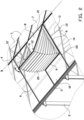
- a greenhouse 1 of the Venlo type is shown in figures 1 and 2 .
- the greenhouse 1 comprises multiple rows of vertical columns 2 for supporting a roof construction 3.
- the roof construction 3 includes a framework with multiple parallel roof ridge profiles 4 and lower rain gutter profiles 5. Adjacent roof ridge profiles 4 and rain gutter profiles 5 are connected to each other by means of slanting window profiles 6.
- the roof ridge profiles 4, the rain gutter profiles 5 and the window profiles 6 are made of a metal, in particular aluminum, and form rectangular rabbets for fixed glass panels 7.
- the roof construction 3 further includes a number of regularly distributed glass panels 8, such as tempered glass panels 8, also called ventilation panels.
- Each of the glass panels 8 is hingeably connected to the adjacent roof ridge profile 4 at the upper side thereof.
- the glass panels 8 are transparent in order to allow light to enter the greenhouse 1. As shown in figure 2 , the glass panels 8 are shorter than the fixed glass panels 7.
- a horizontal window profile 9 is provided between two adjacent slanting window profiles 6 in order to form a rabbet for an additional, smaller glass panel 10 below the glass panel 8.
- the glass panel 8 is configured to hinge around the hinge axis B between the shown open position and a closed position in order to regulate the ventilation of the greenhouse 1.
- the greenhouse 1 is provided with pushing rods 11 connected to distributed connections 12 within the tempered glass panel 8, which pushing rods 11 are coupled to a slide 13 that my move along a horizontal rail 14 by means of an electromotor, in order to move the tempered glass panel 8 into the open or closed position thereof.
- Each of the glass panels 8 is provided with a netting system 20 to prevent passage of insects when the glass panel 8 is in the open position. These can be harmful insects that have to be kept outside the greenhouse 1 or specific insects that are held inside the greenhouse 1.
- the netting system 20 comprises a framework 21 arranged along the free edges of the glass panel 8, and an insect netting 22 of fine mesh gauze. When the glass panel 8 is in the closed position, the framework 21 rests on the horizontal window profile 9 and the adjacent slanting window profiles 6.
- the insect netting is pleated in a bellow configuration in order to stack when it collapses.
- the insect netting 22 is connected with the framework 21 at the upper side thereof, for example by stitching the insect netting 22 to a non-shown stitching web that is oriented downwards from the framework 21.
- the stitching web may be manufactured from rubber, EPDM or the like, and at the lower side the insect netting 22 is connected to the corresponding horizontal window profile 6 and the slanting window profiles 6 along the ventilation opening.
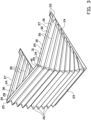
- the insect netting 22, without the framework 21, is shown in figure 3 .
- the insect netting 22 comprises a front panel 23 and two parallel side panels 24.
- the two parallel side panels 24 merge into the front panel 23 at a straight corner 25.
- the two parallel side panels 24 extend substantially transverse or transverse to the hinging axis B of the respective glass panel 8.
- the two parallel side panels 24 and the front panel 23 comprise a number of bellow sections 26 arranged above each other in order to form the pleated configuration of the insect netting.
- Each bellow section 26 has two parallel side bellow portions 27 and a front bellow portion 28.
- Each of the two parallel side bellow portions 27 has a first side gauze web 29 with a first longitudinal side 30 and a second longitudinal side 31, opposite to the first longitudinal side 30, and a second side gauze web 32 also with a first longitudinal side 30 and a second longitudinal side 31, opposite to the first longitudinal side 30.
- the first and second side gauze webs 29, 32 are connected to each other along the second longitudinal side 31 thereof, for example by means of stitching.
- each of the first and second side gauze webs 29, 32 comprises a first web end 33, also called first short site, facing towards the hinging axis B of the glass panel 8, and a second web end 34, also called second short side, facing away from the hinging axis B of the glass panel 8 and towards the front panel 23.
- Each of the front bellow portions 28 has a first front gauze web 35 with a first longitudinal side 36 and a second longitudinal side 37, opposite to the first longitudinal side 36, and a second front gauze web 38 also with a first longitudinal side 36 and a second longitudinal side 37, opposite to the first longitudinal side 36.
- the first and second front gauze webs 35, 38 are connected to each other along the second longitudinal side 37 thereof, for example by means of stitching.
- each of the first and second front gauze webs 35, 37 comprises a first web end 39, facing one of the two parallel side panels 24, and a second web end 40, facing towards the other one of the two parallel side panels 24.
- the front bellow portions 26 and the two side bellow portions 27 are connected to each other by connecting the first side gauze web 29 of the side bellow portions 27 to the first front gauze web 35 of the front bellow portions 26, and by connecting the second side gauze web 32 of the side bellow portions 27 to the second front gauze web 38 of the front bellow portions 26, as is elucidated in more detail in relation to figures 4 and 5 .
- FIG 4 it is shown how the side gauze webs 29, 32 of the side bellow portions 27 are connected to the front gauze webs 35, 38 of the front bellow portions 26 according to the prior art.
- the second web end 34, or the second short side, of the side gauze webs 29, 32 of the side bellow portions 27 is placed on top of the second web end 40 of the front gauze webs 35, 38, or the second web end 40 of the front gauze webs 35, 38 is placed on top of the second web end 34 of the side bellow portions 27, therewith realizing an overlapping area 45.
- the second web end 34, or the second short side of the side gauze webs 29, 32 is located on or at the second longitudinal side 37 of the front gauze webs 35, 38, i.e. the longitudinal side of the front gauze webs facing away from the hinging axis B of the glass panel 8.
- the same is applicable to the first web end 39 of the front gauze webs 35, 38.
- the side gauze webs 29, 32 are stitched to the front gauze webs 35, 38 by means of stitchings 46 along the outer edges of the overlapping area 45.
- FIG 5 it is shown how the side gauze webs 29, 32 of the side bellow portions 27 are connected to the front gauze webs 35, 38 of the front bellow portions 26 according to an embodiment of the invention.
- the second web end 34, or the second short side, of the side gauze webs 29, 32 of the side bellow portions 27 is connected to the first longitudinal side 36 of the front gauze webs 35, 38, i.e. the longitudinal side of the front gauze webs 35, 38 facing towards the hinging axis B of the glass panel 8, at or near the second web end 40 of the front gauze webs 35, 38.
- the second web end 34 of the side gauze webs 29, 32 of the side bellow portions 27 is spaced apart from the second longitudinal side 37 of the of the front gauze webs 35, 38, i.e. the longitudinal side of the front gauze webs 35, 38 facing away from the hinging axis B of the glass panel 8.
- the side gauze webs 29, 32 are interconnected to the front gauze webs 35, 38 by means of welding, therewith forming a welding area 47.
- the first and second web ends 39, 40 of the front gauze webs 35, 38 are connected to each other, for example by means of welding, in order to form front bellow section 28 with closed ends.
- the thickness of the bellow sections 26 at the merger of the side bellow portions 27 into the front bellow portion 28 is decreased in comparison with the thickness of the bellow sections 26 at the merger of the side bellow portions 27 into the front bellow portion 28 of the insect netting 22 according to the prior art as shown in figure 4 .
- This is advantageous, as this results in that the glass panel 8 is enabled to close evenly, such that the framework 21 lies evenly on the horizontal window profile 9.
- Vents at the mergers of the side gauze webs 29, 32 of the side bellow portions 27 to the front gauze webs 35, 38 of the front bellow portions 26 may be improved due to less overlap of the gauze webs 29, 32; 35, 38 at the mergers in comparison to the prior art.
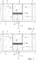
- FIG. 7 In order to illustrate a result of the insect netting 22 according to the invention, a comparison is made between a glass panel 8 in closed position with an insect netting according to an embodiment of the invention, figure 6 , and with an insect netting according to the prior art, figure 7 . It is clearly shown in figure 7 that at least the front portion of the framework 21 parallel to the front panel 23 of the insect netting 22 is warped with respect to the underlying horizontal window profile 9. In particular, the centre of the front portion of the framework 21 is situated closer to the underlying horizontal window profile 9 than the outer ends of the front portion of the framework 21. Warping of the front portion of the framework 21 is caused by the insect netting having a greater thickness at the mergers in comparison to the remaining of the insect netting 22.
- one or more intermediate slanting window profiles 6 located between outer slanting window profiles 6 at which the framework 21 rests when in closed position, are not under load by the glass panel 8. All load applied by the glass panel 8, via the framework 21, is absorbed by the outer slanting window profiles 6 and the underlying horizontal window profile 9.
- the front portion of the framework 21 is substantially parallel to the underlying horizontal window profile 9.
- all load applied by the glass panel 8, via the framework 21 is absorbed by the outer slanting window profiles 6, the underlying horizontal window profile 9 and also the one or more intermediates slanting window profiles.
- the one or more intermediate slanting window profiles therefore, are also under a load when the glass panel 8 is in its closed position.
Landscapes
- Life Sciences & Earth Sciences (AREA)
- Engineering & Computer Science (AREA)
- Structural Engineering (AREA)
- Insects & Arthropods (AREA)
- Pest Control & Pesticides (AREA)
- Architecture (AREA)
- Civil Engineering (AREA)
- Environmental Sciences (AREA)
- Catching Or Destruction (AREA)
Claims (15)
- Insektennetz (22) für ein Gewächshaus (1), wobei das Insektennetz (22) so konfiguriert ist, dass es an einer Lüftungsplatte befestigt werden kann, die um eine Scharnierachse (B) schwenkbar ist, wobei sich das Insektennetz (22) in einer offen-Position der Lüftungsplatte zumindest zwischen einem Öffnungsrand, der sich parallel zur Scharnierachse (B) der Lüftungsplatte erstreckt, und einem Lüftungsplattenrand erstreckt, der sich parallel zu der Scharnierachse (B) der Lüftungsplatte erstreckt,wobei das Insektennetz (22) eine Frontwandung (23) aufweist, die in zwei Seitenwandungen (24) übergeht, wobei das Insektennetz (22) in einer Balgkonfiguration gefaltet ist, um in einer Stapelweise zusammenlegbar zu sein, wobei die Balgkonfiguration mit Balgabschnitten (26) gebildet ist, wobei jeder der Balgabschnitte (26) zwei parallele Seitenbalgabschnitte (27) und einen vorderen Balgabschnitt (28) aufweist,wobei jeder der seitlichen Balgabschnitte (27) eine erste seitliche Gazebahn (29) und eine zweite seitliche Gazebahn (32) aufweist, die an einer Längsseite (31) davon miteinander verbunden sind und die jeweils eine erste kurze Seite, die so konfiguriert ist, dass sie zur Scharnierachse (B) hin zeigt, und eine zweite kurze Seite haben, die dem ersten Bahnende (39) gegenüberliegt und so konfiguriert ist, dass sie von der Scharnierachse (B) weg zeigt, wobei jeder der vorderen Balgabschnitte (28) eine erste vordere Gazebahn (35) und eine zweite vordere Gazebahn (38) aufweist, die an einer Längsseite (37) davon miteinander verbunden sind,dadurch gekennzeichnet, dass die zweite kurze Seite der ersten und der zweiten seitlichen Gazebahn (29, 32) der seitlichen Balgabschnitte (27) zugeordnet mit der Längsseite (36), die zur Scharnierachse (B) der Lüftungsplatte hin zeigt, der ersten und der zweiten vorderen Gazebahn (35, 38) verbunden ist.
- Insektennetz (22) gemäß Anspruch 1, wobei jede von der ersten und der zweiten vorderen Gazebahn (35, 38) ein erstes Bahnende (39) und ein zweites Bahnende (34) hat, das in der Längsrichtung davon dem ersten Bahnende (39) entgegengesetzt ist, wobei die zweite kurze Seite der ersten und der zweiten seitlichen Gazebahn (29, 32) der seitlichen Balgabschnitte (27) zugeordnet mit der Längsseite (36), die zur Scharnierachse (B) der Lüftungsplatte hin zeigt, der ersten und der zweiten vorderen Gazebahn (35, 38) an oder nahe dem ersten oder dem zweiten Bahnende (34, 39) davon verbunden ist.
- Insektennetz (22) gemäß Anspruch 2, wobei die erste und die zweite vordere Gaze-Bahn (35, 38) an dem ersten und dem zweiten Bahnende (34, 39) davon miteinander verbunden sind.
- Insektennetz (22) gemäß Anspruch 1, 2 oder 3, wobei die zweite kurze Seite der ersten und der zweiten seitlichen Gazebahn (29, 32) der seitlichen Balgabschnitte (27) zugeordnet mit der Längsseite (36), die zur Scharnierachse (B) der Lüftungsplatte hin zeigt, der ersten und der zweiten vorderen Gazebahn (35, 38) verschmolzen ist, oder wobei die zweite kurze Seite der ersten und der zweiten seitlichen Gazebahn (29, 32) der seitlichen Balgabschnitte (27) zugeordnet an die Längsseite (36), die zur Scharnierachse (B) der Lüftungsplatte hin zeigt, der ersten und der zweiten vorderen Gazebahn (35, 38) geschweißt ist, oder wobei die zweite kurze Seite der ersten und der zweiten seitlichen Gazebahn (29, 32) der seitlichen Balgabschnitte (27) zugeordnet an die Längsseite (36), die zur Scharnierachse (B) der Lüftungsplatte hin zeigt, der ersten und der zweiten vorderen Gazebahn (35, 38) genäht ist.
- Insektennetz (22) gemäß irgendeinem der vorhergehenden Ansprüche, wobei die Längsseite (37), die von der Scharnierachse (B) weg zeigt, der ersten und der zweiten vorderen Gazebahn (35, 38) zugeordnet von dem ersten und dem zweiten Bahnende der ersten und zweiten seitlichen Gazebahnen (29, 32) im Abstand ist, und/oder wobei die Längsseite (37), die von der Scharnierachse (B) weg zeigt, der ersten und der zweiten vorderen Gazebahn (35, 38) frei von den ersten und zweiten seitlichen Gazebahnen (29, 32) ist, und/oder wobei die Gazebahnen (29, 32, 35, 38) der Bahnabschnitte an einer ersten Längsseite davon (31, 37) miteinander verbunden sind und wobei die Bahnabschnitte an einer zweiten Längsseite (30, 36), die der ersten Längsseite (30, 36) gegenüberliegt, der Gazebahnen (29, 32, 35, 38) miteinander verbunden sind.
- Insektennetz (22) gemäß irgendeinem der vorhergehenden Ansprüche, wobei die Gazebahnen (29, 32, 35, 38) ein gewebtes Textil mit Kettfäden und kreuzenden Schussfäden aufweisen, die abwechselnd über und unter den aufeinanderfolgenden Kettfäden verlaufen, wobei die Kettfäden und die Schussfäden jeweils mindestens einen Faden aufweisen.
- Insektennetz (22) gemäß Anspruch 6, wobei der Faden aus einem Kunststoffharz oder Glasfaser gebildet ist.
- Insektennetz (22) gemäß Anspruch 7, wobei das Kunststoffharz ein Polyolefin ist oder wobei das Kunststoffharz Polyethylen, Polypropylen oder Polyester ist.
- Insektennetz (22) gemäß irgendeinem der vorstehenden Ansprüche, wobei mindestens eine von den Seitenwandungen (24) eine im Wesentlichen dreieckige Form hat, wenn sich die Lüftungsplatte in der offen-Position befindet.
- Insektennetz gemäß Anspruch 9, wobei die zusammenpassenden Enden eines Paars von Balgabschnitten (26), die von der Frontwandung (23) weg zeigen, weiter von der Frontwandung (23) entfernt sind als die zusammenpassenden Enden eines weiteren Paars von Balgabschnitten (26), die von der Frontwandung (23) weg zeigen, wobei das weitere Paar von Balgabschnitten (26) zwischen dem Paar von Balgabschnitten (26) angeordnet ist.
- Insektennetz (22) gemäß irgendeinem der Ansprüche 1-8, wobei die Seitenwandungen (24) einen äußersten Balgabschnitt (26) und mehrere Zwischenbalgabschnitte (26) aufweisen, die entlang innerer Längsränder ihrer Gazebahnen (29, 32, 35, 38) miteinander verbunden sind, wobei die Balgabschnitte (26) alle mit ihrer Vorderseite in die Frontwandung (23) übergehen, wobei die Gazebahnen (29, 32, 35, 38) von jedem Zwischenbalgabschnitt (26) an dem entgegengesetzten hinteren Ende miteinander verbunden sind, wobei das entgegengesetzte hintere Ende des äußersten Balgabschnitts (26) so konfiguriert ist, dass es an oder nahe an der Scharnierachse (B) angeordnet ist, und wobei die hinteren Enden der aufeinanderfolgenden Zwischenbalgabschnitte (26) an den äußersten Balgabschnitt (26) angrenzen und entlang diesem verteilt sind.
- Netzsystem (20) für ein Gewächshaus (1), wobei das Netzsystem (20) aufweist ein Rahmenwerk (21) zum Befestigen des Netzsystems (20) an einer Lüftungsplatte, die um eine Scharnierachse (B) schwenkbar ist, und ein Insektennetz (22) gemäß irgendeinem der vorhergehenden Ansprüche, wobei das Insektennetz (22) mittels Nähens an dem Rahmenwerk (21) befestigt sein kann.
- Gewächshaus (1), wobei das Gewächshaus (1) eine Dachkonstruktion (3) mit einer schrägen oberen Fläche mit einer Öffnung und einer rechteckigen Glasplatte (8) aufweist, welche die Öffnung abdeckt, wobei die Glasplatte (8) an ihrem oberen Rand mit einem Teil der Dachkonstruktion (3) schwenkbar verbunden ist, um um eine Scharnierachse (B) zu schwenken zwischen einer geschlossen-Position, in der sich die Glasplatte (8) im Wesentlichen parallel zu der oberen Fläche erstreckt, und einer offen-Position, in der die Glasplatte (8) schräg bezüglich der oberen Fläche ausgerichtet ist, um einen Lüftungsdurchgang zu bilden,
wobei das Gewächshaus (1) ferner ein Insektennetz gemäß irgendeinem der Ansprüche 1 - 11 oder ein Netzsystem (20) gemäß Anspruch 12 aufweist. - Verfahren zum Herstellen von Balgabschnitten (26) für ein Insektennetz gemäß irgendeinem der Ansprüche 1 - 11, wobei das Verfahren die folgenden Schritte umfasst:- Bereitstellen von zwei oder mehr seitlichen Gazebahnen (29, 32) und zwei oder mehr vorderen Gazebahnen (35, 38),- Verbinden zweier seitlicher Gazebahnen (29, 32) miteinander entlang einer Längsseite (27) davon,- Verbinden zweier vorderer Gazebahnen (35, 38) miteinander entlang einer Längsseite (37) davon, undgekennzeichnet durch Befestigen der zwei verbundenen seitlichen Gazebahnen (29, 32) an den zwei verbundenen vorderen Gazebahnen (35, 38) durch Anordnen und Verbinden der zweiten kurzen Seite der seitlichen Gazebahnen (29, 32) an und mit der Längsseite (36) der vorderen Gazebahnen (35, 38), die so konfiguriert ist, dass sie während des Betriebs zu einer Scharnierachse (B) einer Lüftungsplatte hin zeigt.
- Verfahren gemäß Anspruch 14, wobei die seitlichen Gazebahnen (29, 32) mit den vorderen Gazebahnen (35, 38) durch Schweißen, Verschmelzen oder Nähen verbunden werden.
Applications Claiming Priority (2)
| Application Number | Priority Date | Filing Date | Title |
|---|---|---|---|
| NL2028269A NL2028269B1 (en) | 2021-05-21 | 2021-05-21 | Insect netting for a greenhouse |
| PCT/NL2022/050278 WO2022245215A1 (en) | 2021-05-21 | 2022-05-20 | Insect netting for a greenhouse |
Publications (3)
| Publication Number | Publication Date |
|---|---|
| EP4340593A1 EP4340593A1 (de) | 2024-03-27 |
| EP4340593B1 true EP4340593B1 (de) | 2025-05-07 |
| EP4340593C0 EP4340593C0 (de) | 2025-05-07 |
Family
ID=77627461
Family Applications (1)
| Application Number | Title | Priority Date | Filing Date |
|---|---|---|---|
| EP22726541.0A Active EP4340593B1 (de) | 2021-05-21 | 2022-05-20 | Insektennetz für ein gewächshaus |
Country Status (6)
| Country | Link |
|---|---|
| US (1) | US12575507B2 (de) |
| EP (1) | EP4340593B1 (de) |
| CN (1) | CN117545345B (de) |
| CA (1) | CA3219837A1 (de) |
| NL (1) | NL2028269B1 (de) |
| WO (1) | WO2022245215A1 (de) |
Families Citing this family (3)
| Publication number | Priority date | Publication date | Assignee | Title |
|---|---|---|---|---|
| ES2961394T3 (es) * | 2020-10-13 | 2024-03-11 | Boal Systemen Bv | Un método para aplicar una lámina sobre una estructura de techo inclinado |
| CN119278309A (zh) * | 2022-05-27 | 2025-01-07 | 卢德维格斯文松股份公司 | 防虫网引导系统 |
| EP4356723B1 (de) * | 2023-09-27 | 2025-08-13 | Holland Gaas B.V. | Balgförmiges insektennetz für ein lüftungsfenster eines gewächshauses und gewächshaus |
Family Cites Families (26)
| Publication number | Priority date | Publication date | Assignee | Title |
|---|---|---|---|---|
| GB1251492A (de) * | 1967-10-31 | 1971-10-27 | ||
| NL191553C (nl) * | 1992-11-18 | 1995-09-19 | Leen Huisman Bv | Tuinbouwkas met een scherm van licht en luchtdoorlatend materiaal in een dakopening. |
| NL1003304C2 (nl) * | 1996-06-08 | 1997-12-10 | Leen Huisman B V | Scherminrichting, constructieprofiel en doek daarvoor, en gebouw zoals kas waarin zulks is toegepast |
| NL1007720C2 (nl) * | 1997-12-08 | 1999-09-17 | Holland Scherming B V | Werkwijze voor het vervaardigen van een scherm voor een tuinbouwkas alsmede tuinbouwkas voorzien van een scherm. |
| NL1015820C2 (nl) * | 2000-07-27 | 2002-01-29 | Leen Huisman B V | Schermdoek scherminrichting, en werkwijze. |
| JP3579342B2 (ja) * | 2000-10-10 | 2004-10-20 | セイキ販売株式会社 | 網戸用防虫ネット |
| NL1019229C2 (nl) * | 2001-10-25 | 2003-04-28 | Leen Huisman B V | Scherminrichting en productieproces. |
| NL1020536C2 (nl) * | 2002-05-04 | 2003-11-06 | Leen Huisman B V | Scherminrichting en productieproces. |
| NL1021836C2 (nl) * | 2002-11-04 | 2004-05-18 | P L J Bom Holding B V | Werkwijze voor het vervaardigen van een warenhuis. |
| US20060248807A1 (en) * | 2005-04-15 | 2006-11-09 | Rough Brothers, Inc. | Greenhouse |
| US7568307B1 (en) * | 2008-01-22 | 2009-08-04 | Netafim, Ltd. | Greenhouse structure |
| NL1035203C2 (nl) * | 2008-03-25 | 2009-09-28 | Holland Gaas B V | Kas. |
| KR101042635B1 (ko) * | 2010-11-16 | 2011-06-20 | 화신농건(주) | 방충창 및 이를 구비한 온실 |
| NL2007796C2 (en) | 2011-11-16 | 2013-05-21 | Unilux Nederland B V | Screen device having a pleated corner. |
| AU2015217665B2 (en) * | 2014-02-11 | 2018-09-27 | Nine Ip Limited | Netting materials |
| NL2015156B3 (en) * | 2015-07-10 | 2021-04-13 | Holland Gaas B V | Greenhouse with netting system. |
| US20210332641A1 (en) * | 2020-04-22 | 2021-10-28 | Unseen Screen LLC | Window Screen Systems |
| US20220298857A1 (en) * | 2016-03-23 | 2022-09-22 | Unseen Screen, Llc | Window screen systems |
| WO2017209614A2 (en) * | 2016-06-03 | 2017-12-07 | Horrex Horren B.V. | Insect screen assembly |
| KR102070442B1 (ko) * | 2018-07-24 | 2020-01-28 | 주식회사 케이엔지플러스 | 개폐형 천장구조를 갖는 비닐하우스 |
| US12114625B2 (en) * | 2020-01-22 | 2024-10-15 | Holland Gaas B.V. | Greenhouse with netting system |
| CN212563030U (zh) * | 2020-05-11 | 2021-02-19 | 海宁溯艺门业有限公司 | 一种v型防蚊虫百叶窗帘 |
| CA3219849A1 (en) * | 2021-05-21 | 2022-11-24 | Ab Ludvig Svensson | An insect net lamella and method of producing the same |
| CN119278309A (zh) * | 2022-05-27 | 2025-01-07 | 卢德维格斯文松股份公司 | 防虫网引导系统 |
| US20230349230A1 (en) * | 2022-07-11 | 2023-11-02 | Brad Alan | Retractable window screen |
| EP4356723B1 (de) * | 2023-09-27 | 2025-08-13 | Holland Gaas B.V. | Balgförmiges insektennetz für ein lüftungsfenster eines gewächshauses und gewächshaus |
-
2021
- 2021-05-21 NL NL2028269A patent/NL2028269B1/en active
-
2022
- 2022-05-20 CN CN202280041841.XA patent/CN117545345B/zh active Active
- 2022-05-20 WO PCT/NL2022/050278 patent/WO2022245215A1/en not_active Ceased
- 2022-05-20 US US18/563,370 patent/US12575507B2/en active Active
- 2022-05-20 CA CA3219837A patent/CA3219837A1/en active Pending
- 2022-05-20 EP EP22726541.0A patent/EP4340593B1/de active Active
Also Published As
| Publication number | Publication date |
|---|---|
| NL2028269B1 (en) | 2022-12-06 |
| CN117545345B (zh) | 2025-12-12 |
| EP4340593A1 (de) | 2024-03-27 |
| US12575507B2 (en) | 2026-03-17 |
| CN117545345A (zh) | 2024-02-09 |
| WO2022245215A1 (en) | 2022-11-24 |
| CA3219837A1 (en) | 2022-11-24 |
| US20240268283A1 (en) | 2024-08-15 |
| EP4340593C0 (de) | 2025-05-07 |
Similar Documents
| Publication | Publication Date | Title |
|---|---|---|
| US12575507B2 (en) | Insect netting for a greenhouse | |
| US12114625B2 (en) | Greenhouse with netting system | |
| KR101263858B1 (ko) | 온실지붕구조 | |
| JP2009517569A (ja) | タイル屋根用の封止可能な棟の通気孔 | |
| NL2015156B3 (en) | Greenhouse with netting system. | |
| EP4356723B1 (de) | Balgförmiges insektennetz für ein lüftungsfenster eines gewächshauses und gewächshaus | |
| WO2001065920A1 (en) | A panel for green-house and a ventilation system using the same | |
| EP3984352B1 (de) | Verfahren zum aufbringen einer folie auf eine geneigte dachkonstruktion | |
| CA3069199A1 (en) | Greenhouse with netting system | |
| EP3268552B1 (de) | Gewächshaus | |
| NL2021356B1 (en) | Greenhouse with netting system | |
| KR102902737B1 (ko) | 온실용 조립식 패널 설치구조 | |
| NL2014587B1 (en) | Greenhouse with netting system. | |
| NL2011727C2 (en) | Greenhouse with netting system. | |
| RU2204238C2 (ru) | Теплица | |
| RU239997U1 (ru) | Теплица | |
| KR101581676B1 (ko) | 온실의 지붕창용 방충장치 | |
| NL1023853C2 (nl) | Kas of warenhuis met verbeterde lichtopbrengst. | |
| SK284995B6 (sk) | Hrebeňový a/alebo nárožný vetrací prvok | |
| SU1787366A1 (ru) | Теплица . | |
| EP2702864A1 (de) | Gewächshaus | |
| DE202004011616U1 (de) | Foliendach für ein Gewächshaus | |
| DE3219302C2 (de) | Firstlüftungselement | |
| JPH02285143A (ja) | 換気用重合屋根構造 | |
| JP4265843B2 (ja) | アーチシェルに組み込む平板採光ユニット |
Legal Events
| Date | Code | Title | Description |
|---|---|---|---|
| STAA | Information on the status of an ep patent application or granted ep patent |
Free format text: STATUS: UNKNOWN |
|
| STAA | Information on the status of an ep patent application or granted ep patent |
Free format text: STATUS: THE INTERNATIONAL PUBLICATION HAS BEEN MADE |
|
| PUAI | Public reference made under article 153(3) epc to a published international application that has entered the european phase |
Free format text: ORIGINAL CODE: 0009012 |
|
| STAA | Information on the status of an ep patent application or granted ep patent |
Free format text: STATUS: REQUEST FOR EXAMINATION WAS MADE |
|
| 17P | Request for examination filed |
Effective date: 20231123 |
|
| AK | Designated contracting states |
Kind code of ref document: A1 Designated state(s): AL AT BE BG CH CY CZ DE DK EE ES FI FR GB GR HR HU IE IS IT LI LT LU LV MC MK MT NL NO PL PT RO RS SE SI SK SM TR |
|
| DAV | Request for validation of the european patent (deleted) | ||
| DAX | Request for extension of the european patent (deleted) | ||
| GRAP | Despatch of communication of intention to grant a patent |
Free format text: ORIGINAL CODE: EPIDOSNIGR1 |
|
| STAA | Information on the status of an ep patent application or granted ep patent |
Free format text: STATUS: GRANT OF PATENT IS INTENDED |
|
| INTG | Intention to grant announced |
Effective date: 20241202 |
|
| GRAS | Grant fee paid |
Free format text: ORIGINAL CODE: EPIDOSNIGR3 |
|
| GRAA | (expected) grant |
Free format text: ORIGINAL CODE: 0009210 |
|
| STAA | Information on the status of an ep patent application or granted ep patent |
Free format text: STATUS: THE PATENT HAS BEEN GRANTED |
|
| AK | Designated contracting states |
Kind code of ref document: B1 Designated state(s): AL AT BE BG CH CY CZ DE DK EE ES FI FR GB GR HR HU IE IS IT LI LT LU LV MC MK MT NL NO PL PT RO RS SE SI SK SM TR |
|
| REG | Reference to a national code |
Ref country code: GB Ref legal event code: FG4D |
|
| REG | Reference to a national code |
Ref country code: CH Ref legal event code: EP |
|
| REG | Reference to a national code |
Ref country code: DE Ref legal event code: R096 Ref document number: 602022014345 Country of ref document: DE |
|
| REG | Reference to a national code |
Ref country code: IE Ref legal event code: FG4D |
|
| U01 | Request for unitary effect filed |
Effective date: 20250526 |
|
| U07 | Unitary effect registered |
Designated state(s): AT BE BG DE DK EE FI FR IT LT LU LV MT NL PT RO SE SI Effective date: 20250603 |
|
| U20 | Renewal fee for the european patent with unitary effect paid |
Year of fee payment: 4 Effective date: 20250628 |
|
| PG25 | Lapsed in a contracting state [announced via postgrant information from national office to epo] |
Ref country code: ES Free format text: LAPSE BECAUSE OF FAILURE TO SUBMIT A TRANSLATION OF THE DESCRIPTION OR TO PAY THE FEE WITHIN THE PRESCRIBED TIME-LIMIT Effective date: 20250507 |
|
| PG25 | Lapsed in a contracting state [announced via postgrant information from national office to epo] |
Ref country code: GR Free format text: LAPSE BECAUSE OF FAILURE TO SUBMIT A TRANSLATION OF THE DESCRIPTION OR TO PAY THE FEE WITHIN THE PRESCRIBED TIME-LIMIT Effective date: 20250808 Ref country code: NO Free format text: LAPSE BECAUSE OF FAILURE TO SUBMIT A TRANSLATION OF THE DESCRIPTION OR TO PAY THE FEE WITHIN THE PRESCRIBED TIME-LIMIT Effective date: 20250807 |
|
| PG25 | Lapsed in a contracting state [announced via postgrant information from national office to epo] |
Ref country code: PL Free format text: LAPSE BECAUSE OF FAILURE TO SUBMIT A TRANSLATION OF THE DESCRIPTION OR TO PAY THE FEE WITHIN THE PRESCRIBED TIME-LIMIT Effective date: 20250507 |
|
| PG25 | Lapsed in a contracting state [announced via postgrant information from national office to epo] |
Ref country code: HR Free format text: LAPSE BECAUSE OF FAILURE TO SUBMIT A TRANSLATION OF THE DESCRIPTION OR TO PAY THE FEE WITHIN THE PRESCRIBED TIME-LIMIT Effective date: 20250507 |
|
| PG25 | Lapsed in a contracting state [announced via postgrant information from national office to epo] |
Ref country code: RS Free format text: LAPSE BECAUSE OF FAILURE TO SUBMIT A TRANSLATION OF THE DESCRIPTION OR TO PAY THE FEE WITHIN THE PRESCRIBED TIME-LIMIT Effective date: 20250807 |
|
| PG25 | Lapsed in a contracting state [announced via postgrant information from national office to epo] |
Ref country code: IS Free format text: LAPSE BECAUSE OF FAILURE TO SUBMIT A TRANSLATION OF THE DESCRIPTION OR TO PAY THE FEE WITHIN THE PRESCRIBED TIME-LIMIT Effective date: 20250907 |
|
| REG | Reference to a national code |
Ref country code: CH Ref legal event code: H13 Free format text: ST27 STATUS EVENT CODE: U-0-0-H10-H13 (AS PROVIDED BY THE NATIONAL OFFICE) Effective date: 20251223 |
|
| PG25 | Lapsed in a contracting state [announced via postgrant information from national office to epo] |
Ref country code: SM Free format text: LAPSE BECAUSE OF FAILURE TO SUBMIT A TRANSLATION OF THE DESCRIPTION OR TO PAY THE FEE WITHIN THE PRESCRIBED TIME-LIMIT Effective date: 20250507 |
|
| PG25 | Lapsed in a contracting state [announced via postgrant information from national office to epo] |
Ref country code: CH Free format text: LAPSE BECAUSE OF NON-PAYMENT OF DUE FEES Effective date: 20250531 |
|
| PG25 | Lapsed in a contracting state [announced via postgrant information from national office to epo] |
Ref country code: CZ Free format text: LAPSE BECAUSE OF FAILURE TO SUBMIT A TRANSLATION OF THE DESCRIPTION OR TO PAY THE FEE WITHIN THE PRESCRIBED TIME-LIMIT Effective date: 20250507 |
|
| PG25 | Lapsed in a contracting state [announced via postgrant information from national office to epo] |
Ref country code: SK Free format text: LAPSE BECAUSE OF FAILURE TO SUBMIT A TRANSLATION OF THE DESCRIPTION OR TO PAY THE FEE WITHIN THE PRESCRIBED TIME-LIMIT Effective date: 20250507 |
|
| PG25 | Lapsed in a contracting state [announced via postgrant information from national office to epo] |
Ref country code: MC Free format text: LAPSE BECAUSE OF FAILURE TO SUBMIT A TRANSLATION OF THE DESCRIPTION OR TO PAY THE FEE WITHIN THE PRESCRIBED TIME-LIMIT Effective date: 20250507 |
|
| PLBE | No opposition filed within time limit |
Free format text: ORIGINAL CODE: 0009261 |
|
| STAA | Information on the status of an ep patent application or granted ep patent |
Free format text: STATUS: NO OPPOSITION FILED WITHIN TIME LIMIT |
|
| REG | Reference to a national code |
Ref country code: CH Ref legal event code: L10 Free format text: ST27 STATUS EVENT CODE: U-0-0-L10-L00 (AS PROVIDED BY THE NATIONAL OFFICE) Effective date: 20260318 |
|
| PG25 | Lapsed in a contracting state [announced via postgrant information from national office to epo] |
Ref country code: IE Free format text: LAPSE BECAUSE OF NON-PAYMENT OF DUE FEES Effective date: 20250520 |
|
| 26N | No opposition filed |
Effective date: 20260210 |