EP4340184A1 - Spule, stator und motor - Google Patents
Spule, stator und motor Download PDFInfo
- Publication number
- EP4340184A1 EP4340184A1 EP22807474.6A EP22807474A EP4340184A1 EP 4340184 A1 EP4340184 A1 EP 4340184A1 EP 22807474 A EP22807474 A EP 22807474A EP 4340184 A1 EP4340184 A1 EP 4340184A1
- Authority
- EP
- European Patent Office
- Prior art keywords
- coil
- turn
- region
- turn region
- loss
- Prior art date
- Legal status (The legal status is an assumption and is not a legal conclusion. Google has not performed a legal analysis and makes no representation as to the accuracy of the status listed.)
- Pending
Links
- 239000004020 conductor Substances 0.000 claims abstract description 52
- 239000010949 copper Substances 0.000 claims description 49
- RYGMFSIKBFXOCR-UHFFFAOYSA-N Copper Chemical compound [Cu] RYGMFSIKBFXOCR-UHFFFAOYSA-N 0.000 claims description 46
- 229910052802 copper Inorganic materials 0.000 claims description 46
- 229910052751 metal Inorganic materials 0.000 claims description 21
- 239000002184 metal Substances 0.000 claims description 21
- 229910052782 aluminium Inorganic materials 0.000 claims description 20
- XAGFODPZIPBFFR-UHFFFAOYSA-N aluminium Chemical compound [Al] XAGFODPZIPBFFR-UHFFFAOYSA-N 0.000 claims description 20
- 238000011144 upstream manufacturing Methods 0.000 claims description 18
- XEEYBQQBJWHFJM-UHFFFAOYSA-N Iron Chemical compound [Fe] XEEYBQQBJWHFJM-UHFFFAOYSA-N 0.000 description 20
- 239000000463 material Substances 0.000 description 12
- 229910052742 iron Inorganic materials 0.000 description 10
- 238000004804 winding Methods 0.000 description 10
- 230000008859 change Effects 0.000 description 9
- 241000132092 Aster Species 0.000 description 8
- 230000004907 flux Effects 0.000 description 7
- 239000008186 active pharmaceutical agent Substances 0.000 description 6
- 229910000838 Al alloy Inorganic materials 0.000 description 4
- 229910000881 Cu alloy Inorganic materials 0.000 description 4
- 230000000694 effects Effects 0.000 description 4
- 230000006872 improvement Effects 0.000 description 4
- 230000002093 peripheral effect Effects 0.000 description 4
- 238000003466 welding Methods 0.000 description 4
- 238000000034 method Methods 0.000 description 3
- OKTJSMMVPCPJKN-UHFFFAOYSA-N Carbon Chemical compound [C] OKTJSMMVPCPJKN-UHFFFAOYSA-N 0.000 description 2
- 239000002131 composite material Substances 0.000 description 2
- 239000010931 gold Substances 0.000 description 2
- 230000020169 heat generation Effects 0.000 description 2
- 239000013585 weight reducing agent Substances 0.000 description 2
- BQCADISMDOOEFD-UHFFFAOYSA-N Silver Chemical compound [Ag] BQCADISMDOOEFD-UHFFFAOYSA-N 0.000 description 1
- 230000005540 biological transmission Effects 0.000 description 1
- 229910052799 carbon Inorganic materials 0.000 description 1
- 239000002041 carbon nanotube Substances 0.000 description 1
- 229910021393 carbon nanotube Inorganic materials 0.000 description 1
- 238000005520 cutting process Methods 0.000 description 1
- PCHJSUWPFVWCPO-UHFFFAOYSA-N gold Chemical compound [Au] PCHJSUWPFVWCPO-UHFFFAOYSA-N 0.000 description 1
- 229910052737 gold Inorganic materials 0.000 description 1
- 230000012447 hatching Effects 0.000 description 1
- 239000012212 insulator Substances 0.000 description 1
- 238000005304 joining Methods 0.000 description 1
- 238000010030 laminating Methods 0.000 description 1
- 238000003475 lamination Methods 0.000 description 1
- WABPQHHGFIMREM-UHFFFAOYSA-N lead(0) Chemical compound [Pb] WABPQHHGFIMREM-UHFFFAOYSA-N 0.000 description 1
- 238000004519 manufacturing process Methods 0.000 description 1
- 230000007246 mechanism Effects 0.000 description 1
- 229910052755 nonmetal Inorganic materials 0.000 description 1
- 238000004080 punching Methods 0.000 description 1
- 230000009467 reduction Effects 0.000 description 1
- 239000011347 resin Substances 0.000 description 1
- 229920005989 resin Polymers 0.000 description 1
- 229910052709 silver Inorganic materials 0.000 description 1
- 239000004332 silver Substances 0.000 description 1
- 239000007787 solid Substances 0.000 description 1
- 238000003892 spreading Methods 0.000 description 1
- 230000007480 spreading Effects 0.000 description 1
- 229910052727 yttrium Inorganic materials 0.000 description 1
Images


Classifications
-
- H—ELECTRICITY
- H02—GENERATION; CONVERSION OR DISTRIBUTION OF ELECTRIC POWER
- H02K—DYNAMO-ELECTRIC MACHINES
- H02K3/00—Details of windings
- H02K3/04—Windings characterised by the conductor shape, form or construction, e.g. with bar conductors
- H02K3/18—Windings for salient poles
-
- H—ELECTRICITY
- H02—GENERATION; CONVERSION OR DISTRIBUTION OF ELECTRIC POWER
- H02K—DYNAMO-ELECTRIC MACHINES
- H02K3/00—Details of windings
- H02K3/04—Windings characterised by the conductor shape, form or construction, e.g. with bar conductors
-
- H—ELECTRICITY
- H01—ELECTRIC ELEMENTS
- H01F—MAGNETS; INDUCTANCES; TRANSFORMERS; SELECTION OF MATERIALS FOR THEIR MAGNETIC PROPERTIES
- H01F5/00—Coils
-
- H—ELECTRICITY
- H02—GENERATION; CONVERSION OR DISTRIBUTION OF ELECTRIC POWER
- H02K—DYNAMO-ELECTRIC MACHINES
- H02K3/00—Details of windings
- H02K3/02—Windings characterised by the conductor material
-
- H—ELECTRICITY
- H01—ELECTRIC ELEMENTS
- H01F—MAGNETS; INDUCTANCES; TRANSFORMERS; SELECTION OF MATERIALS FOR THEIR MAGNETIC PROPERTIES
- H01F5/00—Coils
- H01F2005/006—Coils with conical spiral form
-
- H—ELECTRICITY
- H01—ELECTRIC ELEMENTS
- H01F—MAGNETS; INDUCTANCES; TRANSFORMERS; SELECTION OF MATERIALS FOR THEIR MAGNETIC PROPERTIES
- H01F27/00—Details of transformers or inductances, in general
- H01F27/28—Coils; Windings; Conductive connections
- H01F27/30—Fastening or clamping coils, windings, or parts thereof together; Fastening or mounting coils or windings on core, casing, or other support
- H01F27/303—Clamping coils, windings or parts thereof together
-
- Y—GENERAL TAGGING OF NEW TECHNOLOGICAL DEVELOPMENTS; GENERAL TAGGING OF CROSS-SECTIONAL TECHNOLOGIES SPANNING OVER SEVERAL SECTIONS OF THE IPC; TECHNICAL SUBJECTS COVERED BY FORMER USPC CROSS-REFERENCE ART COLLECTIONS [XRACs] AND DIGESTS
- Y02—TECHNOLOGIES OR APPLICATIONS FOR MITIGATION OR ADAPTATION AGAINST CLIMATE CHANGE
- Y02T—CLIMATE CHANGE MITIGATION TECHNOLOGIES RELATED TO TRANSPORTATION
- Y02T10/00—Road transport of goods or passengers
- Y02T10/60—Other road transportation technologies with climate change mitigation effect
- Y02T10/64—Electric machine technologies in electromobility
Definitions
- the present invention relates to a coil, a stator, and a motor.
- the copper loss and loss particularly due to the eddy current (alternating-current loss caused by the eddy current due to the current flowing in the coil and the interlinkage magnetic flux to the coil), which is among the iron loss components, are major causes for the Joule loss.
- a copper (Cu) member, an aluminum (Al) member, and the like are used in general.
- a coil (hereinbelow, a copper-made coil) made mainly of a copper member (copper, a copper alloy, or the like) and a coil (hereinbelow, an aluminum-made coil) made mainly of an aluminum (Al) member (aluminum, an aluminum alloy, or the like) each have advantages and disadvantages.
- the copper-made coil has lower resistance and lower copper loss than the aluminum-made coil but is heavy in weight.
- the aluminum-made coil is lighter, cheaper, and lower in iron loss than the copper-made coil, but has a characteristic of high copper loss.
- an object of the present invention is to provide a coil, a stator, and a motor that can suppress generation of eddy current in the coil and reduce Joule loss.
- the present invention relates to a coil formed by connecting a plurality of one-turn regions each including a turn of a conductor to have a helical structure, wherein the conductor is formed by connecting a first member to a second member in a longitudinal direction, and the plurality of one-turn regions include at least in a part thereof the first member.
- the present invention relates to a coil configured to form a helical structure using a conductor and attached to a stator of a motor, the coil including a plurality of one-turn regions stacked in a direction of a helical axis, wherein out of the one-turn regions, at least a part of a one-turn region near a rotor (hereinbelow referred to as "a near side one-turn region”) is constituted of a first member, and at least a part of a one-turn region far from the rotor (hereinbelow referred to as "a far side one-turn region”) is constituted of a second member.
- a near side one-turn region at least a part of a one-turn region near a rotor
- a far side one-turn region far from the rotor
- the present invention relates to a stator to which the above-described coil is attached.
- the present invention relates to a motor including the above-described coil.
- the present invention relates to a motor including the above-described coil.
- the motor is characterized in that, compared with a case where a motor including a coil in which all of one-turn regions are constituted of the second member and which has an equal shape is assumed to be produced and operated, loss is lower in a high rotation number range than the motor, whereas loss is higher in a low rotation number range than the motor.
- Fig. 1 includes schematic views of a coil 10 according to a first embodiment of the present invention.
- Fig. 1(A) is a front view of the coil 10 having a helical shape as viewed in a direction of an axis (helical axis) SC of the helix
- Fig. 1(B) is a side view as viewed in a direction of a shorter side 104 (for example, the left side of Fig. 1(A))
- Fig. 1(C) is a side view as viewed in a direction of a longer side 103 (for example, the lower side of Fig. 1(A) ).
- some components are appropriately omitted to simplify the drawings.
- the size, shape, thickness, and the like of each member are exaggerated as needed.
- the coil 10 of the present embodiment is obtained by constituting a helical structure body by a long strip-like flat conductor, for example.
- the entire external shape is, for example, an approximately rectangular shape having the shorter side 104 and the longer side 103 in a plan view ( Fig. 1(A) ) and is an approximately quadrangular pyramidal trapezoidal shape having an approximately trapezoidal shape in a side view ( Figs. 1(B) and 1(C) .
- the shorter side 104 and the longer side 103 each includes a straight portion 101.
- an approximately orthogonal corner portion 102a is formed at a part between the straight portions 101. Note that the shape of the coil 10 is illustrative only and is not limited to the example in Fig. 1 .
- the coil 10 has a plurality of one-turn regions CR stacked in the direction of the helical axis SC.
- the "one-turn region” used in the present embodiment refers to each turn of the helical structure body, that is, a region for one turn (one-turn region), illustrated by the dotted arrow in Fig. 1(A) .
- the plurality of one-turn regions CR are illustrated to be separated from each other and are described by using the number of stacked layers in some cases for convenience of description, the respective one-turn regions CR constituting one coil 10 are continuously provided from a starting end 105 to a terminal end 106 of the helical structure body illustrated in Fig. 1(B) since the coil 10 has a helical structure.
- the lower side in Fig. 1(B) is referred to as the starting end 105 while the upper side is referred to as the terminal end 106 for convenience of description, these names may be replaced with each other.
- the coil 10 is a so-called concentrated winding coil in which the plurality of one-turn regions CR are overlapped in the direction of the helical axis SC (up-down direction in Figs. 1(B) and 1(C) ) so that the centers of the one-turn regions CR substantially correspond to the helical axis SC to form a helix.
- the coil 10 is also, for example, an edgewise coil, which forms the helical structure body with a strip-like flat conductor having straight parts (straight portions 101) as illustrated in Fig. 1(A) (in a complete state, the flat conductor is in a wound structure).
- each of the one-turn regions CR has a structure in which one (one piece of) flat conductor makes one turn (is constituted by one turn), and the plurality of one-turn regions CR (for example, six layers in Fig. 1(B) ) are stacked in the direction of the helical axis SC.
- the plurality of one-turn regions CR for example, six layers in Fig. 1(B) .
- a one-turn region in the first layer (first-layer one-turn region) CR1, a one-turn region in the second layer (second-layer one-turn region) CR2, a one-turn region in the third layer (third-layer one-turn region) CR3, a one-turn region in the fourth layer (fourth-layer one-turn region) CR4, a one-turn region in the fifth layer (fifth-layer one-turn region) CR5, and a one-turn region in the sixth layer (sixth-layer one-turn region) CR6 are constituted of a single continuous long strip-like conductor (one flat conductor).
- the order of stacking (laminating) the one-turn regions CR is not limited to that in this example, and the uppermost layer may be referred to as a first layer.
- the number of the one-turn regions CR is illustrative only, and any number is freely selected (the same applies to the following description).
- Fig. 2 includes views describing the details of the coil 10 of the present embodiment, and Figs. 2(A), 2(C), 2(E), and 2(G) are cross-sectional views corresponding to the cross-section along line A-A in Fig. 1(A) .
- a single coil 10 in Fig. 2 includes, for example, four layers of one-turn regions CR, and a description will be given of a case where, similarly to Fig. 1(B) , the first-layer one-turn region CR1, the second-layer one-turn region CR2, ... are provided from the side on which the shorter side 104 is the shorter (the lower layer in Fig.
- Figs. 2(B), 2(D), 2(F), and 2(H) are planar schematic views, assuming that the coils 10 in Figs. 2(A), 2(C), 2(E), and 2(G) are spread out.
- the coil 10 of the present embodiment is a helical structure body formed by continuously connecting a plurality of one-turn regions CR each including one turn of a conductor, and the conductor is formed by connecting a first member 15 (hatched portion in Fig. 2 ) to a second member 16.
- the plurality of one-turn regions CR include at least the first member 15 in a part thereof.
- the plurality of one-turn regions CR include a first one-turn region CRa and a second one-turn region CRb which includes the second member 16. More preferably, the second one-turn region CRb is constituted of only the second member 16.
- the plurality of one-turn regions CR are configured to be stacked in the direction of the helical axis SC.
- the first one-turn region CRa is located on one end (end portion T1) side in the direction of the helical axis SC.
- the second one-turn region CRb is located nearer the other end (end portion T2) side in the direction of the helical axis SC than the first one-turn region CRa.
- the first one-turn region CRa includes the first member 15 in a part thereof, the first member 15 is changed to the second member 16 in the middle of the turn (a connection portion between the first member 15 and the second member 16 exists in the middle of the turn).
- the second one-turn region CRb is constituted of only the second member 16.
- the coil 10 of the present embodiment is constituted of a helical structure body of a continuous conductor (here, one flat conductor), and the conductor is constituted of a plurality of members (the first member 15 and the second member 16).
- At least a part of one or a plurality of layers of one-turn regions CR located on one side of the helical axis SC provided with the end portion T1 is constituted of the first member 15 while one or a plurality of layers of one-turn regions CR located on the other side in the direction of the helical axis SC provided with the end portion T2 are constituted of the second member 16 (do not include the first member 15).
- At least a part of one or a plurality of layers of one-turn regions CR located on the side of the helical axis SC provided with the end portion T1 is constituted of the first member 15 while one or a plurality of layers of one-turn regions CR located on the side in the direction of the helical axis SC provided with the end portion T2 are constituted of only the second member 16 (do not include the first member 15).
- the first member 15 is a conductor (metal) having a higher resistance than that of the second member 16.
- the first member 15 is a metal member composed primarily of aluminum (Al)
- the second member is a metal member composed primarily of copper.
- the "metal composed primarily of aluminum” refers to a metal containing pure aluminum or an aluminum alloy at a proportion of 50% or more of the total. In a case where the metal contains a different component from the pure aluminum or the aluminum alloy, the type and number of the different components are freely selected. Alternatively, the metal may be pure aluminum or a metal in which the content of the aluminum alloy is 100% (or approximately 100%).
- a first metal constituting the first member 15 is referred to simply as "aluminum (Al)" or “an aluminum member” in some cases, which means "a metal composed primarily of aluminum”.
- the "metal composed primarily of copper” refers to a metal containing pure copper or a copper alloy at a proportion of 50% or more of the total. In a case where the metal contains a different component from the pure copper or the copper alloy, the type and number of the different components are freely selected. Alternatively, the metal may be pure copper or a metal in which the content of the copper alloy is 100% (or approximately 100%).
- a second metal constituting the second member 16 is referred to simply as “copper (Cu)" or "a copper member” in some cases, which means "a metal composed primarily of copper”.
- Figs. 2(A) and 2(B) illustrate an example in which the first-layer one-turn region CR1 located on one side of the helical axis SC provided with the end portion T1 is constituted of a combination of the first member 15 and the second member 16. That is, at least a part of the first-layer one-turn region CR1 located on the side of the helical axis SC provided with the end portion T1 (the right side in Fig. 2(A) , and the left side nearer to the starting end 105 in Fig. 2(B) ) is constituted of the first member 15, the other part of the same first-layer one-turn region CR1 (the left side in Fig.
- the first-layer one-turn region CR1 is the first one-turn region CRa
- the second-layer one-turn region CR2 to the fourth-layer one-turn region CR4 are the second one-turn region CRb.
- Fig. 2(B) is a plan view, assuming that the coil 10 in Fig. 2(A) is spread out.
- the coil 10 is constituted by winding one continuous conductor (here, one flat conductor) one turn to form the one-turn region CR and connecting multiple of (four in this case) the one-turn regions CR.
- the first-layer one-turn region CR1 for example, a half turn from, for example, the starting end 105, is constituted of the first member 15, and the rest of the first-layer one-turn region CR1 connected to the half turn is constituted of the second member 16.
- the one-turn regions CR (CR2 to CR4) in the second to fourth layers connected to the first-layer one-turn region CR1 are constituted of only the second member 16.
- Figs. 2(C) and 2(D) illustrate an example in which the entirety of the first-layer one-turn region CR1 located on the side of the helical axis SC provided with the end portion T1 is constituted of the first member 15, and the one-turn regions CR (CR2 to CR4) in the second to fourth layers connected to the first-layer one-turn region CR1 are constituted of the second member 16.
- the first-layer one-turn region CR1 is the first one-turn region CRa
- the second-layer one-turn region CR2 to the fourth-layer one-turn region CR4 are the second one-turn region CRb.
- the entire turn of the first-layer one-turn region CR1 starting from the starting end 105 includes the first member 15, and the second-layer one-turn region CR2 connected to the first-layer one-turn region CR1 and the subsequent part are constituted of only the second member 16.
- Figs. 2(E) and 2(F) illustrate an example in which the entirety of the first-layer one-turn region CR1 located on the side of the helical axis SC provided with the end portion T1 is constituted of the first member 15, a part of the second-layer one-turn region CR2 connected to the first-layer one-turn region CR1 is constituted of a combination of the first member 15 and the second member 16, and the rest is constituted of only the second member 16.
- the entire turn of the first-layer one-turn region CR1 located on the side of the helical axis SC provided with the end portion T1 and at least a part of the second-layer one-turn region CR2 connected to the first-layer one-turn region CR1 are constituted of the first member 15, the other part of the same second-layer one-turn region CR2 (the left side in Fig. 2(E) , that is, for example, the other half turn) is constituted of the second member 16, and the one-turn regions CR (CR3 and CR4) in the third to fourth layers are constituted of only the second member 16.
- the first-layer one-turn region CR1 and the second-layer one-turn region CR2 are the first one-turn region CRa
- the third-layer one-turn region CR3 to the fourth-layer one-turn region CR4 are the second one-turn region CRb.
- the part from the starting end 105 to, for example, the first half of the second-layer one-turn region CR2 are constituted of the first member 15
- the second half of the second-layer one-turn region CR2 connected to the first half is constituted of the second member 16
- the one-turn regions CR (CR3 to CR4) in the third to fourth layers connected to the second half are constituted of only the second member 16.
- Figs. 2(G) and 2(H) illustrate an example in which the first-layer one-turn region CR1 and the second-layer one-turn region CR2 are each constituted of a combination of the first member 15 and the second member 16, and the rest is constituted of only the second member 16. That is, at least a part (the right side in Fig. 2(G) , that is, for example, a half turn on the side nearer to the starting end 105) of the first-layer one-turn region CR1 located on the side of the helical axis SC provided with the end portion T1 includes the first member 15, and the other part (the left side in Fig.
- the second-layer one-turn region CR2 connected to the first-layer one-turn region CR1 (the right side in Fig. 2(G) , that is, for example, a half turn) is constituted of the first member 15, and the other part of the same second-layer one-turn region CR2 (the left side in Fig. 2(G) , that is, for example, the other half turn) is constituted of the second member 16.
- the one-turn regions CR (CR3 to CR4) in the third to fourth layers connected to the second-layer one-turn region CR2 are constituted of only the second member 16.
- the first-layer one-turn region CR1 and the second-layer one-turn region CR2 are the first one-turn region CRa
- the third-layer one-turn region CR3 to the fourth-layer one-turn region CR4 are the second one-turn region CRb.
- the first member 15 and the second member 16 are arranged alternately per half turn, and continuously from the second-layer one-turn region CR2, only the second member 16 is arranged in the one-turn regions CR (CR3 and CR4) in the third to fourth layers.
- the first member 15 may be provided at the other half turn portion corresponding to the left side part in each of the figures.
- the range of the first member 15 in the first one-turn region CRa may be longer or shorter than the half turn.
- the first one-turn region CRa ranges to the second-layer one-turn region CR2
- a configuration in which the third-layer one-turn region CR3 and the subsequent region include the first member 15 (that is, which are the first one-turn region CRa) may be available, and all of the one-turn regions CR in the coil 10 may be the first one-turn region CRa.
- FIG. 3 includes schematic views describing component members of the coil 10, in which Fig. 3(A) is a plan view of the coil 10 in a complete state as viewed in the direction of the helical axis SC (plan view corresponding to Fig. 1(A) ), Figs. 3(B) and 3(C) are plan views illustrating an example of a flat conductor piece C constituting the coil 10, and Figs. 3(D) and 3(E) are enlarged cross-sectional views taken along line B-B in Fig. 3(B) .
- the coil 10 forms a helical structure body by connecting a plurality of strip-like flat conductor pieces (coil pieces) C that can form a helical structure when continuously joined.
- a helical structure body is formed by connecting a plurality of strip-like flat conductor pieces C each including the straight portion 101 with each other along a strip longitudinal direction (helical traveling direction) BL at the straight portions 101 thereof, making end faces TS of the coil pieces C in the helical traveling direction abut on each other to press (pressure-weld, for example, cold-pressure-weld) the end faces TS, and continuously joining the flat conductor pieces C to have a desired number of times of winding.
- pressure-weld for example, cold-pressure-weld
- a single one-turn region CR is constituted of one flat conductor piece C or the connected flat conductor pieces C.
- Each of the one-turn regions CR has approximately orthogonal corner portions and has a (approximately) rectangular shape on the outer peripheral side and the inner peripheral side in a plan view ( Fig. 3(A) and Fig. 1(A) ) as viewed in the direction of the helical axis SC of the coil 10.
- the flat conductor piece C may sometimes be referred to as the coil piece C.
- the flat conductor piece (coil piece) C of the present embodiment is, for example, a conductor in which a cross-section (cross-section along the line B-B) when cut in a direction (strip transverse direction BS) perpendicular (orthogonal) to the straight portion in the strip longitudinal direction BL (traveling direction of the helical structure) has a rectangular shape as illustrated in Fig. 3(D) or a rectangular shape having rounded corners as illustrated in Fig. 3(E) . That is, the coil piece C has two opposed first surfaces (here, wider surfaces) WS and two opposed second surfaces (here, narrower surfaces) WT and is a strip-like member elongated in a predetermined direction.
- the cross-section orthogonal to the strip longitudinal direction has a (approximately) rectangular shape as illustrated in Fig. 3(D) will be described.
- the plurality of coil pieces C are connected at the end faces thereof, for example, with the surfaces being in an aligned state.
- the "surfaces being in aligned state” refers to, in a case where the cross-sectional shape of each coil piece C is not a longitudinally and transversely symmetrical shape such as a square, a round wire, or the like (in a case where the cross-sectional shape is an approximately rectangular shape as in Fig. 3(D) ), "a state where the shapes of the two coil pieces C are aligned so that the corresponding surfaces face in the same direction (for example, so that the corresponding surfaces face upward)".
- each of the two coil pieces has the first surface WS which is wider and the second surface WT which is narrower as illustrated in Fig. 3(D)
- the two coil pieces C are aligned and connected so that the wider surfaces (first surfaces WS) face upward.
- the lengths (the sizes and the shapes of the end faces) of the two coil pieces C in the wider direction may differ from each other.
- first surface WS is the wider surface while the second surface WS is the narrower surface
- the first surface WS may be the narrower surface while the second surface WT may be the wider surface
- the cross-sectional shape may be an approximately square shape in a cross-sectional view in which the first surface WS and the second surface WT are equivalent in length.
- the aforementioned connection with the "surface being in the aligned state" is illustrative only, and the present invention is not limited to this.
- the two coil pieces C may be connected so that the first surface of one coil piece C which is wider and the second surface WT of the other coil piece C which is narrower may face in the same direction (for example, so that they may face upward without the surfaces being aligned).
- Each of the coil pieces C is obtained, for example, by punching a plate-like metal (for example, a metal having a thickness of about 0.1 mm to 5 mm) into a desired shape and has at least one straight portion 101 and at least one corner portion 102.
- the corner portion 102 is a portion that is bent so as to change the extending direction of the strip longitudinal direction BL.
- At least one (preferably, all) of the corner portions 102 is preferably a corner portion having a non-curved (for example, approximately orthogonal) shape.
- the corner portion 102 is an approximately square shaped region as illustrated by hatching in Fig. 1(A) .
- the end face TS of the coil piece C of the present embodiment is located at the straight portion 101 of the coil piece C except the corner portion 102.
- the shape of the coil piece C is not limited to this and may be, for example, an approximately L shape or an approximately C shape.
- the plurality of coil pieces C may all have the same shape or may be a combination of different shapes. Further, in a case where the coil pieces C having different shapes are combined, a coil piece C having a linear shape (I shape) provided with no corner portion 102 may be included.
- a coil piece welded portion 13 as a result of pressure welding is formed in the straight portion 101 of the one-turn region CR except the corner portion 102 as illustrated in Figs. 3(A) and 1(A) .
- the coil 10 is one continuous long strip-like flat conductor formed by connection of the plurality of coil pieces C as illustrated in Fig. 2 , and a plurality of one-turn regions (one-turn regions CR) are formed.
- one coil 10 can be constituted by a plurality of members (the first member 15 and the second member 16). More specifically, the coil 10 in a complete form is configured to have a helical structure body of a long strip-like flat conductor, and the first member 15 and the second member 16 can be mixed in the elongated direction (longitudinal direction). Furthermore, the position and the length thereof (arranging region in the longitudinal direction) can freely be selected. With this configuration, for example, a half turn portion of a certain one-turn region CR can include the first member 15 while the other half turn portion can include the second member 16. As a result, the coil 10 in which only a desired region includes the first member 15 as illustrated in Fig. 2 can be obtained.
- Fig. 2 schematically illustrates the linear shape as a description of the arranging state of the first member 15 and/or the second member 16 constituting each of the one-turn regions CR from the starting end 105 to the terminal end 106.
- the coil 10 can be formed by connecting the plurality of coil pieces C each punched into a desired shape (for example, a U shape having an approximately orthogonal corner portion 102 (corner portion)), the shape (particularly, the shape on the inner peripheral side) of the plan view ( Fig. 3(A) ) of the coil 10 can be made an approximately rectangular shape. Accordingly, for example, in a case where the coil 10 is attached to a stator of a motor, the space factor of the coil 10 can be increased. As a result, the motor using the coil 10 can achieve low resistance and high efficiency.
- a desired shape for example, a U shape having an approximately orthogonal corner portion 102 (corner portion)
- the shape (particularly, the shape on the inner peripheral side) of the plan view ( Fig. 3(A) ) of the coil 10 can be made an approximately rectangular shape. Accordingly, for example, in a case where the coil 10 is attached to a stator of a motor, the space factor of the coil 10 can be increased. As a result, the
- the coil 10 of the present embodiment is attached to the stator of a motor, for example.
- a tooth of the stator core
- the first member 15 is arranged near one end portion (the end portion T1 in the above description) of the helical axis SC.
- the arranging region of the first member 15 is determined on the basis of the positional relationship with the rotor. This will be described below.
- Fig. 4 includes schematic views illustrating a part of a motor 70 including the coil 10 of the present embodiment, in which Fig. 4(A) is a schematic plan view of a rotor 60 and a stator 50 as viewed in a direction of a rotation shaft of the motor 70 (rotor 60), and Fig. 4(B) is a schematic side view in a case where the motor 70 is arranged so that the rotation shaft extends in the up-down direction of the figure.
- the motor 70 of an inner rotor type in which the rotor 60 is arranged on the inner side (inner circumferential side) of the stator 50 will be described.
- Fig. 4(C) is an enlarged view of the part provided with the coil 10 in Fig.
- Fig. 4(A) as a cross-sectional view ( Fig. 2(A), 2(C), 2(E), or 2(G) ) corresponding to the cross-section along the line A-A in Fig. 1(A) .
- Fig. 4(D) is a schematic front view of one coil in Fig. 4(C) as viewed in the direction of the helical axis SC (rotation shaft of the motor 70).
- the motor 70 for example, a single-phase motor or a three-phase motor
- the motor for example, a single-phase motor or a three-phase motor
- the shaft 80 is a columnar member and is rotated around the central axis thereof while being supported by, for example, a bearing (not illustrated).
- a device (not illustrated) to be driven is connected via a power transmission mechanism such as a gear.
- the rotor 60 is provided with a magnet in the circumferential direction thereof and is rotated together with the shaft 80 although detailed illustration of the rotor 60 is omitted.
- the stator 50 is arranged on the outer side of the rotor 60 in the radial direction, for example, and generates power to rotate the rotor 60 by means of the coil 10 arranged in the circumferential direction.
- An external terminal of the stator 50 is connected via, for example, a lead wire to a driving circuit or power supply (both not illustrated) that supply electric power to the motor.
- the stator 50 includes a plurality of coils 10 and an annular stator member (stator core) 52 having a plurality of teeth 51 arranged annularly.
- the coil 10 is similar to one described above and is covered on the periphery thereof (periphery of the flat conductor) with an insulating resin (not illustrated here) or the like, for example, in continuity with the helical traveling to insulate the respective one-turn regions CR from one another.
- the coil 10 is attached to each of the teeth 51 via, for example, an insulator (not illustrated).
- the motor 70 supplies driving current from the power supply or the driving circuit to the coil 10 via a wiring member such as a bus bar (not illustrated). By doing so, magnetic flux is generated in (the teeth 51 of) the stator 50. Then, due to the effect of the magnetic flux between the teeth 51 and the magnet, torque in the circumferential direction is generated. As a result, the rotor 60 is rotated with respect to the stator 50 around the central axis of the shaft 80.
- a rotation direction R of the rotor 60 at the time of normal operation is a predetermined direction (counterclockwise direction in the illustrated example).
- FIG. 1 An example of a method for attaching the coil 10 formed as the helical structure body having an approximately quadrangular pyramidal trapezoidal shape as illustrated in Fig. 1 is as follows.
- the teeth 51 are formed to be attachable to and detachable from the inside surface of the stator member 52 by, for example, a not-illustrated engaging (fitting) unit or the like.
- the teeth 51 are inserted into the coil 10 (axial center portion) and are secured to the stator member 52.
- the teeth 51 have a flange portion 51A, similar to a bobbin, on one side thereof in the direction of the helical axis SC of the coil 10. This structure prevents the coil 10 from coming off of the tooth 51.
- the tooth 51 may have a cassette form that can be separated (split) and engaged along the direction of the helical axis SC of the coil 10 so as to have a configuration in which the two cassettes are inserted into the coil 10 from both sides (sides provided with the end portions T1 and T2, respectively) of the coil 10 in the direction of the helical axis SC and are engaged while being nipped to attach the coil 10 to the tooth 51, and in which the tooth 51 is attached to the stator member 52.
- each coil 10 having an approximately quadrangular pyramidal trapezoidal shape
- the coil 10 is attached so that the one-turn region CR whose shorter side 104 is the shortest (the first-layer one-turn region CR1 in the above-described example) is arranged on the side provided with the flange portion 51A or on the side nearest to the rotor 60.
- the coil 10 of the present embodiment is attached to the stator 50 so that the helical axis SC thereof is located in a virtual cutting plane VS (the large dotted line in Fig. 4(A) and the cross-section in Fig. 4(B) ) including a rotation shaft central line C1 of the motor 70 (rotor 60) and extends in the diameter direction of the stator 50 or the rotor 60.
- the virtual cutting plane VS which includes the rotation shaft central line C1 of the rotor 60, may be rephrased as a cross-section whose cutting line is a line segment corresponding to the diameter of the rotor 60.
- a near side one-turn region CRN at least a part of the one-turn region near the rotor 60 (hereinbelow referred to as "a near side one-turn region CRN"), out of the plurality of one-turn regions CR stacked in the direction of the helical axis SC, is constituted of the first member 15 while at least a part of the one-turn region far from the rotor 60 (hereinbelow referred to as "a far side one-turn region CRF”) is constituted of the second member 16. That is, the near side one-turn region CRN includes the first one-turn region CRa while the far side one-turn region CRF includes the second one-turn region CRb.
- At least a part of the one-turn region CR of the near side one-turn region CRN is constituted of the first member 15 while the one-turn region CR of the far side one-turn region CRF is constituted of only the second member 16.
- each one-turn region CR is near or far from the rotor 60 is determined with reference to a center (hereinbelow referred to as "a stacking direction center C2") in a stacking direction of the one-turn regions CR in the coil 10 (a lamination direction or a direction along the length of the helical axis SC) as illustrated in Figs. 4(B) and 4(C) .
- a stacking direction center C2 in a stacking direction of the one-turn regions CR in the coil 10 (a lamination direction or a direction along the length of the helical axis SC) as illustrated in Figs. 4(B) and 4(C) .
- one or a plurality of layers of one-turn regions CR located nearer the side provided with the rotor 60 than the stacking direction center C2 are referred to as the near side one-turn region CRN while one or a plurality of layers of one-turn regions CR farther from the rotor 60 than the stacking direction center C2 are referred to as the far side one-turn region CRF.
- At least a part of at least the one-turn region CR (first-layer one-turn region CR1) nearest the rotor 60 (that is, on the innermost circumferential side of the stator 50 in the case of the inner rotor type) out of the near side one-turn regions CRN includes the first member 15. More specifically, at least a part of a half-turn region in a certain one-turn region CR (for example, the first-layer one-turn region CR) is provided with the first member 15.
- each of the one-turn regions CR is divided into a first half-turn region HR1 and a second half-turn region HR2. These are classified as an upstream side and a downstream side in terms of the rotation direction of the rotor 60.
- the first half-turn region HR1 is a half-turn region on an upstream US side (a rotation rear side or a rotation source side) in the rotation direction of the rotor 60 while the second half-turn region HR2 is a half-turn region on a downstream DS side (a rotation destination side) in the rotation direction of the rotor 60.
- At least one one-turn region CR (specifically, at least the first-layer one-turn region CR1 nearest to the rotor 60) in the near side one-turn region CRN of the coil 10
- at least a part (in this example, the entirety of the first half-turn region HR1) of the first half-turn region HR1 on the upstream US side in the rotation direction of the rotor 60 is constituted of the first member 15.
- at least a part (in this example, the entirety of the second half-turn region HR2) of the second half-turn region HR2 is constituted of the second member 16.
- the second half-turn region HR2 of the first-layer one-turn region CR1 and the second-layer one-turn region CR2 connected thereto to the fourth-layer one-turn region CR4 are constituted of the second member 16 as illustrated in Figs. 2(A) and 2(B) .
- the arrangement region of the first member 15 is determined from an analysis result of Joule loss in the coil.
- the analysis of Joule loss in the coil conducted by the present applicant will be described with reference to Figs. 5 to 8 .
- the hysteresis loss is caused by changes of the magnetic flux density in relation to the magnetic field of a member (material), but the member (in this example, the copper member and the aluminum member) generally used for the coil 10 generates almost no magnetic flux density even in the magnetic field.
- a coil for a motor a coil (hereinbelow, a copper-made coil) made of a copper member in its entirety (in all of the one-turn regions CR) and a coil (hereinbelow, an aluminum-made coil) made of an aluminum member in its entirety (in all of the one-turn regions CR) are known.
- Fig. 5 schematically illustrates a general relationship between rotation number (%) and loss (W) of a motor.
- the loss caused by the heat of the motor mainly includes so-called copper loss L1, iron loss L2, and machine loss L3.
- the copper loss L1 does not change in relation to the rotation number since the copper loss is based on a value unique to the member.
- the iron loss L2 and the machine loss L3 tend to increase as the rotation number increases (speed-up).
- Joule loss is generated in the coil at the time of driving the motor. It can be concluded that the Joule loss generated in the coil is mostly caused by the copper loss (power loss generated from winding resistance (R) of the coil and flowing current (I)) and the eddy current loss (alternating-current loss caused by the eddy current due to the current flowing in the coil and the interlinkage magnetic flux to the coil).
- FIGs. 5(B) and 5(C) are schematic views illustrated by replacing the relationship between the rotation number and the loss of the motor illustrated in Fig. 5(A) with a relationship, in a case where a certain coil is used in a motor, between rotation number of the motor and Joule loss generated in the coil at the time of driving the motor.
- Fig. 5(A) is a view schematically illustrating a relationship between Joule loss generated in a copper-made coil and motor rotation number
- Fig. 5(B) is a view schematically illustrating a relationship between Joule loss generated in an aluminum-made coil and motor rotation number.
- the direction of the horizontal axis represents rotation number (rotation speed (r/min)), and the direction of the vertical axis represents loss (Joule loss (w)). Also, here, particularly from the viewpoint of the component materials for the coil, the relationship between the copper loss L1 and the iron loss L2 is schematically illustrated, and the iron loss L2 particularly indicates the eddy current loss (the same applies to the following description).
- the present applicant conducted experiments in which a motor that uses a copper-made coil having an original shape and a motor that uses an aluminum-made coil having an original shape are each operated under various conditions.
- the coil used in the experiments is, similarly to the coil 10 of the present embodiment illustrated in Fig. 1 and the like, a coil configured to have approximately rectangular outer and inner peripheral shapes in a plan view by connecting a plurality of coil pieces C to have a helical structure.
- the coil with this configuration is a coil having a shape that the present applicant has originally developed and is hereinbelow referred to as an "Aster coil" for convenience of description. All of the coils described below are Aster coils.
- the copper-made coil is a coil obtained by constituting the coil 10 illustrated in Fig. 4(C) by a copper member in its entirety (100%), and the configuration of the motor 70 other than the coil is similar to that in Figs. 4(A) and 4(B) . Also, the rotation direction of the rotor 60 is a counterclockwise direction.
- Fig. 6 (A) illustrates an analysis result of Joule loss density [W/m 3 ] generated in the copper-made coil
- Fig. 6 (B) is an enlarged view of Fig. 6 (A) .
- Joule loss was locally concentrated on a region (circled) particularly on the upstream US side in the rotation direction of the rotor 60 in the one-turn region CR nearest to the rotor 60 (first-layer one-turn region CR1) in the copper-made coil.
- the region on which Joule loss is locally concentrated in the copper-made coil is referred to as a "Joule loss concentrated region J".
- Joule loss was generated less on the downstream DS side in the rotation direction of the rotor 60 and less at a place farther from the rotor 60. Note that the Joule loss in this analysis includes the copper loss and the eddy current loss.
- the measured value as the Joule loss density in the Joule loss concentrated region J was a maximum of, for example, about 7 ⁇ 10 7 [W/m 3 ] to about 10 ⁇ 10 7 [W/m 3 ]
- the measured value on the downstream DS side in the rotation direction of the rotor 60 even in the same one-turn region CR was about 6 ⁇ 10 7 [W/m 3 ] at most
- the measured value in the second-layer one-turn region CR2 even on the upstream US side in the rotation direction of the rotor 60 was about 3 ⁇ 10 7 [W/m 3 ] at most.
- Fig. 7 is a pie chart illustrating the result.
- the loss in the region that is, the first half-turn region HR1 of the first-layer one-turn region CR1 nearest to the rotor 60 and located on the upstream US side in the rotation direction of the rotor 60 accounts for about 60 to 70 percent of the total.
- the coil had some regions (portions) in which the eddy current loss is lower than a reference value (for example, a value of the eddy current loss in the entire coil (such as an average value of eddy current loss values in plural portions of the coil) and other regions (portions) in which the eddy current loss is higher than the reference value.
- a reference value for example, a value of the eddy current loss in the entire coil (such as an average value of eddy current loss values in plural portions of the coil) and other regions (portions) in which the eddy current loss is higher than the reference value.
- Fig. 8(A) is a schematic view of a long member in a plan view obtained by spreading out the coil
- Figs. 8(B) to 8(E) are views schematically illustrating the relationship between the rotation number of the motor using the Aster coil and the Joule loss generated in the coil at the time of driving the motor in a similar manner to Figs. 5(B) and 5(C)
- Figs. 8(B) and 8(C) illustrate a case of the copper-made coil
- Figs. 8(D) and 8(E) illustrate a case of the aluminum-made coil.
- Figs. 8(F) and 8(G) illustrate a case where the coil 10 of the present embodiment is used in the motor 70.
- the direction of the horizontal axis represents rotation number (rotation speed (r/min)) of the coil
- the direction of the vertical axis represents loss (Joule loss (w)).
- the coil includes a region (portion) A in which the eddy current loss L2 is low and a region (portion) B in which the eddy current loss L2 is high (refer to Figs. 6 and 7 ).
- a region including the region A and a region including the region B, setting the "eddy current loss L2 in the entire coil" as a reference (center), will be described.
- the "eddy current loss L2 in the entire coil" as a reference is a value obtained by dividing each of the first-layer one-turn region CR1 to the fourth-layer one-turn region CR4 into the first half-turn region HR1 and the second half-turn region HR2, calculating the eddy current loss L2 for each of the eight half-turn regions for one coil, and summing up the values.
- Fig. 8(A) illustrates the member divided into the regions A and B on the left and right for convenience of description, and it does not mean that Fig. 8(A) corresponds to the plan view in Fig. 2 .
- Each of Figs. 8(B), 8(D), and 8(F) is a schematic view illustrating the relationship between the rotation number of the motor and the Joule loss generated in the coil at the time of driving the motor in the region A, where the eddy current loss L2 is low, in the coil and each of Figs.
- 8(C), 8(E), and 8(G) is a schematic view illustrating the relationship between the rotation number of the motor and the Joule loss generated in the coil at the time of driving the motor in the region B, where the eddy current loss L2 is high, in the coil.
- each of Figs. 8(B) and 8(C) is a schematic view in a case where the motor using the copper-made coil is operated in a certain range including the high rotation number Y.
- the range of the eddy current loss L2 illustrated by the dotted triangle in each of Figs. 8(B) and 8(C) represents the eddy current loss L2 (value obtained by calculating the eddy current loss for each of the eight half-turn regions for one coil and summing up the values) in the entire coil as a reference.
- the eddy current loss L2 As illustrated in Fig. 8(B) , in the region A, where the eddy current loss is low, the eddy current loss L2, as illustrated by the solid line, is lower than the reference eddy current loss (dotted line), and the change amount (slope) is also low.
- the loss values are conceptual values used merely for convenience of description of the magnitude relationship and are not values having other meanings (for example, representing the ratio) (as for Fig. 8 , the same applies to the following description).
- the eddy current loss L2 in the region B, where the eddy current loss is high, the eddy current loss L2, as illustrated by the solid line, is higher than the reference eddy current loss (dotted line), and the change amount (slope) is also high.
- FIG. 8(D) and 8(E) is a schematic view in a case where the motor using the aluminum-made coil is operated in a certain range including the high rotation number Y.
- the range of the eddy current loss L2 illustrated by the dotted triangle in each of Figs. 8(D) and 8(E) represents the eddy current loss in the entire coil as a reference.
- the eddy current loss L2 in the region A, where the eddy current loss L2 is low, the eddy current loss L2, as illustrated by the solid line, is lower than the reference eddy current loss (dotted line), and the change amount (slope) is also low.
- the eddy current loss L2 in the case of the aluminum-made coil operated at the same high rotation number Y in the region B where the eddy current loss is high (region where the eddy current loss is higher than the reference eddy current loss (dotted line)), the eddy current loss L2, as illustrated by the solid line, is higher than the reference eddy current loss (dotted line), and the change amount (slope) is also high.
- the change amount seems not to be as high as in the case of the copper-made coil.
- the present applicant has conceived that, in a case of operation in a range including the high rotation number Y, in the region B where the eddy current loss L2 is high, the magnitude relationship between the Joule loss in the aluminum-made coil and the Joule loss in the copper-made coil is reversed ( Figs. 8(C) and 8(E) ).
- the present applicant has conceived that, by using as a coil 10 used in a motor 70 a copper member, in which the copper loss L1 having a large percentage of the Joule loss is relatively low, as a base material, that is, using the copper-made coil as a base material, and using in combination a member having a higher resistance value than the copper member (for example, an aluminum member) partially in the Joule loss concentrated region J of the copper-made coil, the Joule loss concentrated region J of the copper-made coil can be reduced or eliminated.
- Figs. 8(F) and 8(G) are schematic views in a case where the motor 70 using the coil 10 (coil made of a copper member and an aluminum member) of the present embodiment is operated in a certain range including the high rotation number Y.
- the range of the eddy current loss L2 illustrated by the dotted triangle in each of Figs. 8(F) and 8(G) represents the eddy current loss in the entire coil as a reference.
- Fig. 8(F) is a copy of Fig. 8(B)
- Fig. 8(G) is a copy of Fig. 8(E) .
- the present applicant has arrived at the coil 10 of the present embodiment using the second member 16 (for example, a copper member) having a relatively low resistance value (having a low copper loss L1) as a base member for the coil and including the first member 15 (for example, an aluminum member) having a relatively low eddy current loss L2 (having a relatively high resistance value) only in a partial region including the Joule loss concentrated region J in a coil (for example, a copper-made coil) constituted of only the base member (second member 16) in its entirety.
- the second member 16 for example, a copper member having a relatively low resistance value (having a low copper loss L1)
- the first member 15 for example, an aluminum member
- L2 having a relatively high resistance value
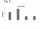
- Fig. 9 is a graph making a comparison of the Joule loss generated in the entire coil in a case where motors respectively using the conventional coils and the coils 10 of the present embodiment are operated in the aforementioned range including the high rotation number Y.
- the Joule loss generated in the entire coil is a value obtained by calculating the Joule loss for each of the eight half-turn regions for one coil and summing up the values.
- "a" is the copper-made coil
- "b” is the aluminum-made coil.
- “c” is the coil 10 constituted of a composite material in which the entirety of the first-layer one-turn region CR1 is constituted of the first member 15 and the rest is constituted of the second member 16 as illustrated in Fig.
- “d” is the coil 10 constituted of a composite material in which the first half-turn region HR1 of the first-layer one-turn region CR1 is constituted of the first member 15, and the rest is constituted of the second member 16 as illustrated in Figs. 2(A) and 4 in the present embodiment.
- the four types of coils have the same in terms of the size of the coil, the shape of the conductor (flat conductor), and the number of times of winding.
- the coil 10 of the present embodiment can reduce Joule loss drastically as compared with the copper-made coil and the aluminum-made coil.
- the Joule loss of the copper-made coil (a) is higher than that of the aluminum-made coil (b) in a range including the high rotation number Y. That is, this result coincides with the magnitude relationship of the Joule loss values (Joule loss (for example, value 45) of entire copper-made coil > Joule loss (for example, value 42) of entire aluminum-made coil) in the explanation using the schematic views in Figs. 8(B) to 8(E) .
- the motor 70 using the coil 10 of the present embodiment has a lower loss in a high rotation number range (range including the high rotation number Y) than the motor using the copper-made coil (the Joule loss of the coil 10 is lower than that of the coil (copper-made coil) of the motor), whereas the motor 70 has higher loss in a low rotation number range (range including the low rotation number X) than the motor using the copper-made coil (the Joule loss of the coil 10 is higher than that of the copper-made coil).
- a high rotation number range range including the high rotation number Y
- the motor using the copper-made coil the Joule loss of the coil 10 is lower than that of the coil (copper-made coil) of the motor
- the motor 70 has higher loss in a low rotation number range (range including the low rotation number X) than the motor using the copper-made coil (the Joule loss of the coil 10 is higher than that of the copper-made coil).
- a high load range (a range including the high rotation number Y, a high torque range) is more effective for the motor 70 than improvement in a low load range (a range including the low rotation number X, a low torque range).
- improvement of Joule loss in a high load range for the motor 70 is set as one of purposes, and the motor 70 including the coil 10 of the present embodiment is used, preferably particularly, in an operation range including the high rotation number (rate of rotation) Y.
- the "operation range including the high rotation number Y" in the present embodiment is, for example, a range of rotation number (rate of rotation) in which the eddy current loss L2 is generated, and an example thereof is, in a case where a range from the lowest value to the highest value (maximum allowable rotation number Z) of rotation number of the motor 70 (when used normally) is 100 (%), a range from 20 to 100 (%), preferably a range from 30 to 100 (%).
- the range is an operation range in which current having a frequency of dozens of Hz is input, preferably an operation range in which current having a frequency of 100 Hz or higher is input.
- a method for controlling the motor of the present embodiment includes, in a case where a motor including a conventional copper-made coil having the same shape is assumed to be operated, operating the motor 70 under a condition under which a high rotation number range (frequency) in which the motor 70 including the coil 10 of the present embodiment has a lower Joule loss than the motor including the conventional copper-made coil is included. By doing so, generation of eddy current loss in the entire operation range of the motor can be suppressed, and Joule loss can be reduced.
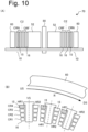
- Fig. 10 includes vies illustrating an example of an outer-rotor type motor in which the rotor 60 is arranged on the outer side (outer circumferential side) of the stator 50 as another example of the motor 70, in which Fig. 10(A) is a lateral cross-sectional view corresponding to Fig. 4(B) , and Fig. 10(B) is a plan view corresponding to Fig. 4(C) .
- the outermost coil 10 in the radial direction of the stator 50 is the coil 10 nearest to the rotor 60.
- each coil 10 having an approximately quadrangular pyramidal trapezoidal shape for example, the coil 10 is attached so that the one-turn region CR (the fourth-layer one-turn region CR4 in the above-described example) whose shorter side 104 is the longest is arranged on the side provided with the flange portion 51A or on the side nearest to the rotor 60.
- the rotation direction of the rotor 60 is, for example, a clockwise direction.
- At least a part (the hatched half-turn region (first half-turn region HR1)) of the one-turn region CR (in this example, the fourth-layer one-turn region CR4) nearest to the rotor 60 at least on the upstream US side in the rotation direction of the rotor 60 is constituted of the first member 15 while the rest is constituted of the second member 16.
- Joule loss can be reduced. That is, this can be achieved, and similar effects can be obtained even in a case where the motor 70 is of the outer-rotor type.
- the coil 10 of the present embodiment is configured to have a helical structure of one (single linear or single strip-like) long member, and the long member is constituted of a conductor in which a plurality of (two) different types of materials are connected in the longitudinal direction.
- One (first member 15) of the different types of materials is a member that has a higher resistance value than the other (second member 16) and which can suppress generation of eddy current.
- the first member 15 is arranged at least in the Joule loss concentrated region J of a coil, assumed to produced, constituted of the second member 16 in its entirety. Specifically, it is desirable that at least a region nearest to the rotor 60 and located on the upstream US side in the rotation direction of the rotor 60 be constituted of the first member 15.
- the Joule loss concentrated region J in a case of a copper-made coil (100A) does not exist in the shorter side 104 or the like of the one-turn region CR, only the longer side 103 (straight portion 101) and the corner portions (direction changing portions) 102 on both sides thereof may be constituted of the first member 15, for example, as illustrated by the dotted line in Fig. 4(D) .
- the minimum unit of the first member 15 is not limited to the half-turn region of the one-turn region CR.
- eddy current loss is less influenced by a magnet as the distance from the rotor 60 is longer.
- the Joule loss concentrated region J is negligible, if any, in the third-layer one-turn region CR3 and the fourth-layer one-turn region CR4. That is, in the present embodiment, all of the one-turn regions CR in the far side one-turn region CRF may be constituted of the second member 16.
- a region in the copper-made coil (100A) in which the Joule loss equal to or higher than a certain threshold value is generated is preferably set as the Joule loss concentrated region J, as needed.
- the region including at least the Joule loss concentrated region J is preferably constituted of the first member 15, and the other regions is preferably constituted of the second member 16 as needed.
- the certain threshold value in this case is, for example, a certain ratio (for example, 0.3 times, 0.5 times, 1.2 times, 1.5 times, or preferably 1.7 times) in a case where the Joule loss of the entire coil 10 is 100, and a region including a portion in which Joule loss equal to or higher than the ratio is generated can be set as the Joule loss concentrated region J.
- a certain ratio for example, 0.3 times, 0.5 times, 1.2 times, 1.5 times, or preferably 1.7 times
- an average value of the Joule loss values in a plurality of predetermined portions (for example, one-turn regions CR) in the coil 10 can be set as the threshold value, and a region including a portion in which Joule loss equal to or higher than the average value is generated can be set as the Joule loss concentrated region J.
- Joule loss (average) may be calculated in each of eight cross-sections of the respective portions of each coil 10 (eight cross-sections including the first-layer one-turn region CR1 to the fourth-layer one-turn region CR4 of the first half-turn region HR1 and the first-layer one-turn region CR1 to the fourth-layer one-turn region CR4 of the second half-turn region HR2) (refer to Fig. 6 ), and the portion including the cross-section in first place (to third place, for example) in descending order of Joule loss may be set as the Joule loss concentrated region J.
- the arranging region of the first member 15 is appropriately selected according to the generation region of the Joule loss concentrated region J in the copper-made coil. That is, on condition that at least a part of the one-turn region CR nearest to the rotor 60 is composed of the first member 15, various arranging examples can be selected, such as the arranging examples illustrated in Fig. 2 .
- the first member 15 can easily be arranged in a desired freely-selected portion.
- arranging the first member 15 in a portion in the one-turn region CR (near the rotor 60) on the upstream US side in the rotation direction of the rotor 60 may further be a condition.
- the upstream US in the rotation direction and the downstream DS in the rotation direction are switched when the rotation direction of the rotor 60 is reversed.
- the Joule loss can be lower than those in the cases of the copper-made coil and an aluminum-made coil 100B (refer to Fig. 9 ).
- the half turn portions (for example, the first half-turn region HR1) on the upstream US side in the rotation direction of the rotor 60 in a plurality of respective one-turn regions CR near the rotor 60 (for example, the first-layer one-turn region CR and the second-layer one-turn region CR) may be constituted of the first member 15. That is, the first member 15 may be arranged once every half turn ( Fig. 2(H) ).
- At least a part of the other one-turn regions CR in the near side one-turn region CRN may be constituted of the first member 15 (may include the first member 15). Also, the number of layers of the one-turn regions CR including the first member 15 may be one or plural.
- At least a part of the one-turn regions CR in the near side one-turn region CRN is preferably constituted of the first member 15 (preferably includes the first member 15), and at least a part nearest to the rotor 60 on the upstream US side in the rotation direction of the rotor 60 is more preferably constituted of the first member 15.
- the arranging region of the first member 15 is appropriately selected according to the characteristics and the cost required for the motor 70.
- the coil 10 in which the first half-turn region HR1 is constituted of the first member 15 is preferably employed from a viewpoint of the cost and the weight reduction.
- the entire turn of the first-layer one-turn region CR1 is preferably constituted of the first member 15.
- the coil 10 whose external shape is an approximately quadrangular pyramidal trapezoidal shape, in which the one-turn region whose shorter side 104 is the shortest is the first-layer one-turn region CR1, and the one-turn region whose shorter side 104 is the longest is the fourth-layer one-turn region CR4 or the sixth-layer one-turn region CR6.
- the direction of stacking (the order of stacking) the one-turn regions CR is not limited to this example, and the one-turn region CR whose shorter side 104 is the longest may be the first-layer one-turn region CR1. That is, only required is a configuration in which, regardless of the order of stacking the one-turn regions CR, a part of the one-turn region near (nearest to) the rotor 60 is constituted of the first member 15.
- the present invention is not limited to the aforementioned embodiment and can be configured in various embodiments.
- the external shape of the coil 10 is not limited to the approximately quadrangular pyramidal trapezoidal shape and may be an approximately rectangular solid shape or an approximately cubic shape.
- the coil 10 may be constituted of another conductor instead of the coil piece C made of the flat conductor. That is, the "conductor" in the above-described embodiment includes a flat conductor, a round wire, and a square wire.
- the coil 10 may not only be formed by pressure welding the coil pieces C having the corner portions 102 (is not limited to the Aster coil) but may also be formed by winding a long conductor which is as long as a helical structure in a complete state.
- the coil 10 as illustrated in Fig. 2 may be formed so that the first member 15 may reside in a desired region when the coil 10 is completed, for example, by preparing respective linear coil pieces (coil pieces of flat conductor, round wire, or square wire) of the first member 15 and the second member 16, pressure-welding and connecting them, and winding the connected conductor in a helical form.
- each of the one-turn regions is formed by the conductor making one turn (is constituted by one turn of the conductor), and the plurality of (for example, six layers in Fig. 1(B) , and four layers in Fig. 2 and the like) one-turn regions CR are stacked in the direction of the helical axis SC.
- the present invention is not limited to this, and as long as the first member 15 is a material having a relatively high resistance compared to that of the second member, the present invention can be implemented in a similar manner and similar effects can be obtained even in a case where these members are made of other conductors (including non-metal conductors).
- a combination of the first member 15 and the second member 16 can be selected from combinations of members constituted mainly of silver (Ag), copper (Cu), gold (Au), aluminum (Al), or carbon (C, carbon nanotube).
Landscapes
- Engineering & Computer Science (AREA)
- Power Engineering (AREA)
- Windings For Motors And Generators (AREA)
Applications Claiming Priority (2)
| Application Number | Priority Date | Filing Date | Title |
|---|---|---|---|
| JP2021081485A JP7170345B1 (ja) | 2021-05-13 | 2021-05-13 | コイル、ステータ、モータおよびコイルの製造方法 |
| PCT/JP2022/019822 WO2022239775A1 (ja) | 2021-05-13 | 2022-05-10 | コイル、ステータ、モータ |
Publications (2)
| Publication Number | Publication Date |
|---|---|
| EP4340184A1 true EP4340184A1 (de) | 2024-03-20 |
| EP4340184A4 EP4340184A4 (de) | 2024-11-20 |
Family
ID=84027189
Family Applications (1)
| Application Number | Title | Priority Date | Filing Date |
|---|---|---|---|
| EP22807474.6A Pending EP4340184A4 (de) | 2021-05-13 | 2022-05-10 | Spule, stator und motor |
Country Status (5)
| Country | Link |
|---|---|
| US (1) | US20240364163A1 (de) |
| EP (1) | EP4340184A4 (de) |
| JP (1) | JP7170345B1 (de) |
| CN (1) | CN117413449A (de) |
| WO (1) | WO2022239775A1 (de) |
Families Citing this family (8)
| Publication number | Priority date | Publication date | Assignee | Title |
|---|---|---|---|---|
| JP2019033888A (ja) * | 2017-08-15 | 2019-03-07 | 株式会社三洋物産 | 遊技機 |
| JP2019033889A (ja) * | 2017-08-15 | 2019-03-07 | 株式会社三洋物産 | 遊技機 |
| JP2019033890A (ja) * | 2017-08-15 | 2019-03-07 | 株式会社三洋物産 | 遊技機 |
| JP2020163054A (ja) * | 2019-03-29 | 2020-10-08 | 株式会社三洋物産 | 遊技機 |
| JP2020163059A (ja) * | 2019-03-29 | 2020-10-08 | 株式会社三洋物産 | 遊技機 |
| JP2020163056A (ja) * | 2019-03-29 | 2020-10-08 | 株式会社三洋物産 | 遊技機 |
| JP2020163052A (ja) * | 2019-03-29 | 2020-10-08 | 株式会社三洋物産 | 遊技機 |
| JP2020163057A (ja) * | 2019-03-29 | 2020-10-08 | 株式会社三洋物産 | 遊技機 |
Family Cites Families (22)
| Publication number | Priority date | Publication date | Assignee | Title |
|---|---|---|---|---|
| JP3747318B2 (ja) * | 2002-02-01 | 2006-02-22 | ミネベア株式会社 | 制動モータ |
| JP2004153874A (ja) * | 2002-10-28 | 2004-05-27 | Nissan Motor Co Ltd | モータの固定子 |
| KR101096469B1 (ko) * | 2003-07-10 | 2011-12-20 | 마그네틱 애플리케이션 인크. | 소형 고전력 교류 발전기 |
| US20050046299A1 (en) * | 2003-08-25 | 2005-03-03 | Brown David L. | Windings for electric machines |
| JP4623129B2 (ja) * | 2008-04-21 | 2011-02-02 | 株式会社デンソー | 回転電機の固定子及び回転電機 |
| JP2010183741A (ja) * | 2009-02-05 | 2010-08-19 | Aisin Aw Co Ltd | 電機子 |
| US8841811B2 (en) * | 2010-08-18 | 2014-09-23 | Remy Technologies Llc | Conductor insulation arrangement for an electric machine |
| JP5261539B2 (ja) * | 2011-06-13 | 2013-08-14 | トヨタ自動車株式会社 | 電磁石型回転電機 |
| JP5742805B2 (ja) * | 2012-09-13 | 2015-07-01 | トヨタ自動車株式会社 | 回転電機の固定子 |
| DE102013100216B4 (de) * | 2012-12-13 | 2014-12-24 | Fraunhofer-Gesellschaft zur Förderung der angewandten Forschung e.V. | Elastisch verformbarer sportausrüstungsgegenstand mit einer verformbaren elektromagnetischen spulenstruktur |
| WO2014188466A1 (ja) * | 2013-05-20 | 2014-11-27 | 三菱電機株式会社 | 固定子及びこの固定子を使用する電動機 |
| DE112014003897B4 (de) * | 2013-08-26 | 2024-01-18 | Mitsubishi Electric Corporation | Elektrische Rotationsmaschine |
| CN108141082B (zh) * | 2015-10-29 | 2020-03-06 | 三菱电机株式会社 | 旋转电机 |
| DE102016108712A1 (de) * | 2016-05-11 | 2017-11-16 | Wobben Properties Gmbh | Synchrongenerator einer getriebelosen Windenergieanlage sowie Verfahren zum Herstellen eines Synchrongenerators und Verwendung von Formspulen |
| CN106787335A (zh) * | 2016-12-16 | 2017-05-31 | 华中科技大学 | 一种混合导体绕组结构及具有该结构的电机及其应用 |
| DE102017207659B4 (de) * | 2017-05-08 | 2019-11-14 | Audi Ag | Elektrische Maschine sowie Verfahren zum Herstellen einer elektrischen Maschine |
| JP6906701B2 (ja) * | 2018-06-01 | 2021-07-21 | 三菱電機株式会社 | 固定子、電動機、圧縮機、及び空気調和装置 |
| JP6929603B2 (ja) | 2018-06-26 | 2021-09-01 | ダイハツ工業株式会社 | 回転機 |
| US12057265B2 (en) * | 2018-07-17 | 2024-08-06 | Aster Co., Ltd. | Coil manufacturing apparatus and coil manufacturing method |
| JP7172809B2 (ja) * | 2019-04-08 | 2022-11-16 | 株式会社デンソー | 回転電機 |
| JP7417236B2 (ja) * | 2019-05-08 | 2024-01-18 | 株式会社アスター | ステータ部材、ステータおよびモータ |
| JP6795267B1 (ja) | 2019-09-12 | 2020-12-02 | 三菱電機株式会社 | 交流回転機の制御装置 |
-
2021
- 2021-05-13 JP JP2021081485A patent/JP7170345B1/ja active Active
-
2022
- 2022-05-10 WO PCT/JP2022/019822 patent/WO2022239775A1/ja not_active Ceased
- 2022-05-10 EP EP22807474.6A patent/EP4340184A4/de active Pending
- 2022-05-10 US US18/290,278 patent/US20240364163A1/en active Pending
- 2022-05-10 CN CN202280034776.8A patent/CN117413449A/zh active Pending
Also Published As
| Publication number | Publication date |
|---|---|
| CN117413449A (zh) | 2024-01-16 |
| WO2022239775A1 (ja) | 2022-11-17 |
| US20240364163A1 (en) | 2024-10-31 |
| EP4340184A4 (de) | 2024-11-20 |
| JP2022175240A (ja) | 2022-11-25 |
| JP7170345B1 (ja) | 2022-11-14 |
Similar Documents
| Publication | Publication Date | Title |
|---|---|---|
| EP4340184A1 (de) | Spule, stator und motor | |
| JP4878002B2 (ja) | 電磁機器 | |
| US6242840B1 (en) | Electrical machine including toothless flux collector made from ferromagnetic wire | |
| US9413200B2 (en) | Stator and electric motor using same | |
| JP5229381B2 (ja) | モータ用導線およびモータ用コイル | |
| CN110492630B (zh) | 旋转电机 | |
| JP5195804B2 (ja) | 回転電機の回転子 | |
| JP7300585B2 (ja) | モータ | |
| CN111971763A (zh) | 线圈以及使用该线圈的电动机 | |
| JP2012186938A (ja) | 電機子 | |
| JP2008512072A (ja) | リニア式ないしローテーション式4極同期直接駆動モーター | |
| JP2009136090A (ja) | ロータプレート | |
| JP2004153874A (ja) | モータの固定子 | |
| JP5034376B2 (ja) | 磁心、電機子、回転電機及び圧縮機 | |
| CN110476326A (zh) | 线圈和使用该线圈的马达 | |
| US11909284B2 (en) | Flat-type stator with multilayer coils for disc-type motor | |
| JP2011234443A (ja) | コイルおよび電機子 | |
| US12068653B2 (en) | Coil, stator member, stator, and motor | |
| EP3422372A1 (de) | Rauschfilter | |
| JP5710312B2 (ja) | 超電導コイル装置 | |
| JP2012110114A (ja) | コイル | |
| WO2023063403A1 (ja) | 回転電機用固定子 | |
| JP5972154B2 (ja) | 回転電機 | |
| JP6049240B2 (ja) | コイル部品 | |
| JP7535686B2 (ja) | モータ |
Legal Events
| Date | Code | Title | Description |
|---|---|---|---|
| STAA | Information on the status of an ep patent application or granted ep patent |
Free format text: STATUS: THE INTERNATIONAL PUBLICATION HAS BEEN MADE |
|
| PUAI | Public reference made under article 153(3) epc to a published international application that has entered the european phase |
Free format text: ORIGINAL CODE: 0009012 |
|
| STAA | Information on the status of an ep patent application or granted ep patent |
Free format text: STATUS: REQUEST FOR EXAMINATION WAS MADE |
|
| 17P | Request for examination filed |
Effective date: 20231128 |
|
| AK | Designated contracting states |
Kind code of ref document: A1 Designated state(s): AL AT BE BG CH CY CZ DE DK EE ES FI FR GB GR HR HU IE IS IT LI LT LU LV MC MK MT NL NO PL PT RO RS SE SI SK SM TR |
|
| DAV | Request for validation of the european patent (deleted) | ||
| DAX | Request for extension of the european patent (deleted) | ||
| STAA | Information on the status of an ep patent application or granted ep patent |
Free format text: STATUS: EXAMINATION IS IN PROGRESS |
|
| A4 | Supplementary search report drawn up and despatched |
Effective date: 20241017 |
|
| RIC1 | Information provided on ipc code assigned before grant |
Ipc: H02K 3/02 20060101ALI20241011BHEP Ipc: H01F 27/28 20060101ALI20241011BHEP Ipc: H01F 5/00 20060101ALI20241011BHEP Ipc: H02K 3/18 20060101AFI20241011BHEP |
|
| 17Q | First examination report despatched |
Effective date: 20241029 |