TECHNICAL FIELD
The invention relates to an electric motor and a stator used for the electric motor.
BACKGROUND ART
In a conventional stator, a stator core is made of stacked steel plates. An insulator is embedded in the stator core. The insulator is an insulator made of a synthetic resin. The annular stator core is formed with tooth portions protruding in a diametrically inward direction at a plurality of points at which an inner periphery thereof is equally divided in a circumferential direction. Wire materials are wound around the respective tooth portions through the insulator, so that a plurality of layers of windings is formed. In the wire materials configuring the winding, one layer of the innermost side is an aluminum wire, and other five layers of the outer sides are copper wires (refer to Patent Document 1).
In another conventional stator, an insulator is disposed in a stator slot of a stator iron core. Main windings are accommodated at an inner side of the insulator. The main windings are formed by winding main magnet wires into an irregular winding. The number of the magnet wires is 34 wires, for example. Auxiliary windings are accommodated in spaces formed between the adjacent main windings. The auxiliary windings are formed by winding auxiliary magnet wires by the same number as the main windings. A wire diameter of the auxiliary magnet wire is 154/1000 of the main magnet wire.
In another conventional stator, aluminum is used for the auxiliary magnet wire forming the auxiliary windings. Copper is used for the magnet wire of the main windings (refer to Patent Document 2).
PRIOR ART DOCUMENT
Patent Document
[Patent Document 1] JP-A-2010-183788 (for example, paragraphs [0028], [0030] and [0032], and FIG. 1)
[Patent Document 2] JP-A-H10-174330 (for example, paragraphs [0009] and [0018], and FIG. 1)
SUMMARY OF THE INVENTION
Problems that the Invention is to Solve
Patent Documents 1 and 2 disclose the technology where the copper wire and the aluminum wire are used for the windings of the stator. However, Patent Documents 1 and 2 do not disclose a configuration for reducing a resistance of the winding when materials having different electrical resistivities are used for the winding.
It is therefore an object of the present invention to provide a configuration capable of reducing a resistance of a winding when materials having different electrical resistivities are used for the winding.
Means for Solving the Problems
A stator according to the present invention includes a cylindrical stator core; a plurality of tooth portions formed along a circumferential direction of the stator core, and windings disposed in a plurality of slots formed between the tooth portions and wound around the tooth portions. The windings are
(1) configured by materials having different electrical resistivities,
(2) a ratio of a sectional area of a material having a high electrical resistivity to a sectional area of a material having a low electrical resistivity in the slot is equal to or larger than 1, and
(3) is equal to or smaller than a ratio of the electrical resistivity of the material having the high electrical resistivity to the electrical resistivity of the material having the low electrical resistivity.
Advantage of the Invention
According to the present invention, when the materials having different electrical resistivities are used for the winding, it is possible to reduce the resistance of the winding.
BRIEF DESCRIPTION OF THE DRAWINGS
FIG. 1 illustrates an electric motor according to a first embodiment of the present invention.
FIG. 2 is a sectional view of a stator according to the first embodiment of the present invention.
FIG. 3 is a partial sectional view of the stator according to the first embodiment of the present invention.
FIG. 4 is a partial sectional view of the stator according to a second embodiment of the present invention.
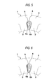
FIG. 5 is a partial sectional view of the stator according to a third embodiment of the present invention.
FIG. 6 is a partial sectional view of the stator according to a fourth embodiment of the present invention.
FIG. 7 is a partial sectional view of the stator according to a fifth embodiment of the present invention.
FIG. 8 is a table showing a combination of electric wire materials and a ratio of electrical resistivities according to the first to fifth embodiments of the present invention.
EMBODIMENTS FOR CARRYING OUT THE INVENTION
First Embodiment
A structure of an electric motor according to a first embodiment of the present invention will be described with reference to FIG. 1. FIG. 1 illustrates a structure of the electric motor according to the first embodiment.
As shown in FIG. 1, the electric motor includes a rotor, which is a part that rotates (referred to as a rotor in the following description), and a stator, which is a part that generates a rotational force for the rotor (referred to as a stator 1 in the following description). A shaft is fixed to a diametrical center of the rotor. The rotor is configured by a plurality of permanent magnets. The stator 1 has a cylindrical shape and is configured to cover the rotor from a diametrically outer side. The stator 1 is configured by disposing a plurality of coils about a shaft in a circumferential direction. An alternating current power supply supplies an alternating current to the coils of the stator 1. Also, a load is connected to the shaft.
The coils of the stator 1 generate a magnetic flux (φ), as shown in FIG. 1, when the current flows through the coils. The permanent magnets of the rotor are applied with a magnetic force in a direction of the magnetic flux (φ). The rotor is driven by the magnetic force applied to the permanent magnets.
Subsequently, operations of the electric motor will be described. When rotating the rotor, a direction of a magnetic field generated by the coils is sequentially moved in the circumferential direction. This can be implemented by supplying the alternating current to the coils of the stator 1. The coils of the stator 1 generate a magnetic field (hereinafter, referred to as a rotating magnetic field) in a clockwise or counterclockwise direction. In the example of FIG. 1, the coils generate a rotating magnetic field in the clockwise direction. The permanent magnets are applied with a magnetic force in the rotating direction of the rotating magnetic field. The permanent magnets are pulled to the rotating magnetic field, so that the rotor is rotated in the same direction of the rotating magnetic field.
When the rotor is rotated, the shaft is rotated together with the shaft. A rotational force of the shaft is transmitted to the load. That is, the rotational force generated for the rotor is transmitted to the load through the shaft.
In the below, a configuration of the stator 1 of the first embodiment is described. FIG. 2 is a sectional view of the stator 1 according to the first embodiment. As shown in FIG. 2, the stator 1 is mainly configured by a stator core 2 having a cylindrical shape and tooth portions 3. As shown in FIG. 2, the tooth portions 3 are provided on an inner periphery of the stator core 2. In the first embodiment, 12 tooth portions 3 are provided in the stator 1 along a circumferential direction shown in FIG. 2.
Slots 4 are provided between the respective tooth portions 3. The slot 4 is a space part between the respective tooth portions 3. In the first embodiment, the 12 slots 4 are provided in the stator 1 along the circumferential direction shown in FIG. 2.
FIG. 3 is a partial sectional view of the stator 1 according to the first embodiment of the present invention, in which a C part of FIG. 2 is enlarged. In FIG. 3, the stator core 2 is provided with the tooth portions 3. The slots 4 are provided between the respective tooth portions 3. An insulating paper 5 is provided along a shape of the slot 4 in the slot 4.
As shown in FIG. 3, a copper wire 6 a and an aluminum wire 6 b are provided in the same slot 4. The copper wire 6 a and the aluminum wire 6 b are wound around the tooth portions 3. Hereinafter, the copper wire 6 a and the aluminum wire 6 b will be collectively referred to as windings 6.
Subsequently, a principle of the first embodiment will be described. A resistance of the winding 6 is denoted by a winding resistance R. When electric wires A, B are used as the windings 6, the winding resistance R is expressed by a following equation 1.
In the equation 1, ρA and ρB indicate electrical resistivities of the electric wires A, B, respectively. nA and nB indicate the number of turns of the electric wires A, B, respectively. L indicates an average circumferential length. SA and SB indicate sectional areas of the electric wires A, B, respectively. ‘a’ is a constant determined by the number of slots and a wire connection method of the windings 6.
Also, a relation between an area AS of the slot 4 and the sectional areas SA, SB of the electric wires A, B is expressed by a following equation 2.
[Mathematical 2]
As×η=S A ×n A +S B n B (Equation 2)
In the equation 2, η indicates a space factor. The space factor is a ratio of an occupying area of the windings 6 to the area AS of the slot 4.
Also, a total sum of the numbers of turns of the electric wire A and the electric wire B is denoted by N. In the total sum N of the number of turns, a ratio of the electric wire A is referred to as ‘x’. Also, the sectional area SB of the electric wire B is referred to as ‘y’ times as large as the sectional area SA of the electric wire A. Here, a following equation 3 is deduced from the equation 2.
Accordingly, the winding resistance R(x, y) is expressed by a following equation 4 from the equations 1 and 3.
When the sectional areas SA, SB of the electric wires A, B are the same, the winding resistance is R(x, 1). A condition for making the winding resistance R(x, y) smaller than R(x, 1) is expressed by a following equation 5.
From the equation 5, a following equation 6 is deduced.
As can be seen from the equation 6, in case of 1<y<ρB/ρA, the winding resistance R(x, y) of the electric wires A, B coexisting in the same slot becomes smaller, as compared to the case where the sectional areas SA, SB of the electric wires A, B are the same. Also, the equation 1<y<ρB/ρA is a mathematical equation to deduce two following points. A first point is a configuration where a ratio of a sectional area of a material having a high electrical resistivity to a sectional area of a material having a low electrical resistivity in the slot 4 is equal to or larger than 1. A second point is a configuration where the ratio is equal to or smaller than a ratio of the electrical resistivity of the material having the high electrical resistivity to the electrical resistivity of the material having the low electrical resistivity.
Also, as can be seen from the equation 6, in case of y=ρB/ρA, the winding resistance R(x, y) of the electric wires A, B coexisting in the same slot 4 is equivalent to the case where the sectional areas SA, SB of the electric wires A, B are the same.
Next, a configuration of the stator 1 of the first embodiment will be described in detail. In the first embodiment, as shown in FIG. 3, the copper wire 6 a is used as the electric wire A and the aluminum wire 6 b is used as the electric wire B. Also, as shown in FIG. 3, a winding method of the copper wire 6 a and the aluminum wire 6 b is concentrated winding.
In FIG. 3, an area D indicates an area that is occupied by the copper wire 6 a in the slot 4. That is, the area D is a total sum of the sectional areas of the copper wire 6 a in the slot 4. In FIG. 3, an area E indicates an area that is occupied by the aluminum wire 6 b in the slot 4. That is, the area E is a total sum of the sectional areas of the aluminum wire 6 b in the slot 4. In FIG. 3, a ratio of the area E occupied by the aluminum wire 6 b to a summed area of the area D and the area E is larger than 50% and smaller than 61%.
Here, the electrical resistivity ρA of copper is 16.8 nΩ·m. The electrical resistivity ρB of aluminum is 26.5 nΩ·m. Also, the sectional area of the copper wire 6 a is referred to as SCu, and the sectional area of the aluminum wire 6 b is referred to as SAl.
As described above, y is (the sectional area of the electric wire B)/(the sectional area of the electric wire A). Therefore, it can be shown that y=SAl/SCu. Thus, ‘1<y<ρB/ρA’ of the equation 6 can be replaced with a following equation 7.
Also, a following equation 8 is satisfied.
From the equations 7 and 8, a following equation 9 is deduced.
That is, as shown by the equation 9, the ratio of an occupying area of the aluminum wire 6 b in the slot 4 to an occupying area of the windings 6 in the slot 4 is set to be larger than 50% and smaller than 61%. Here, the occupying area is a product of the sectional area of the electric wire and the number of turns.
In other words, in FIG. 3, an area ratio of the area E occupied by the aluminum wire 6 b to the summed area of the area D and the area E is set to be larger than 50% and smaller than 61%. Thereby, as described with reference to the equation 6, the winding resistance R can be reduced, as compared to the case where the sectional area SCu of the copper wire 6 a and the sectional area SAl of the aluminum wire 6 b are the same.
Here, a configuration where the occupying area of the copper wire 6 a and the occupying area of the aluminum wire 6 b are the same in the same slot 5 may be possible. Also, the ratio of the occupying area of the aluminum wire 6 b in the slot 4 to the occupying area of the windings 6 in the slot 4 may be set to be 61%.
Second Embodiment
Hereinafter, configurations of the stator 1 and the electric motor according to a second embodiment will be described. The same or equivalent means and configurations as the first embodiment are denoted with the same terms and reference numerals, and the descriptions thereof are omitted.
In the second embodiment, a stator is particularly described in which a ratio of a sectional area of a material having a high electrical resistivity to a sectional area of a material having a low electrical resistivity in the slot is equivalent to a square root of a ratio of the electrical resistivity of the material having the high electrical resistivity to the electrical resistivity of the material having the low electrical resistivity.
FIG. 4 is a partial sectional view of the stator 1 according to the second embodiment of the present invention, in which the C part of FIG. 2 is enlarged.
As shown in FIG. 4, the copper wire 6 a and the aluminum wire 6 b are provided in the same slot 4. The copper wire 6 a and the aluminum wire 6 b are wound around the tooth portions 3 of the stator core 2. Also, as shown in FIG. 4, the winding method of the copper wire 6 a and the aluminum wire 6 b is concentrated winding.
In FIG. 4, the number of turns of the windings 6 disposed in the same slot 4 is 20 turns. Also, an occupying area of the windings 6 provided in the same slot 4 is 55% of the area of the slot 4.
Also, in the second embodiment, as shown in FIG. 4, the numbers of turns of the copper wire 6 a and the aluminum wire 6 b are 10 turns, respectively. A wire diameter of the copper wire 6 a is 0.45 mm. A wire diameter of the aluminum wire 6 b is 0.55 mm.
Next, a principle of the second embodiment will be described. In order to obtain a minimum value of the winding resistance R(x, y), the equation 4 of the first embodiment is partially differentiated with respect to y. Thereby, a following equation 10 is deduced.
In the equation 10, the minimum value of the winding resistance R(x, y) is obtained when a following equation 11 is satisfied.
From the equations 10, 11, a following equation 12 is deduced.
That is, from the equation 12, when a following equation 13 is satisfied, the winding resistance R(x, y) becomes smallest.
Next, the configuration of the stator 1 of the second embodiment will be described in detail. In the second embodiment, as shown in FIG. 4, the copper wire 6 a is used as the electric wire A, and the aluminum wire 6 b is used as the electric wire B.
In the second embodiment, a ratio of the sectional areas of the copper wire 6 a and the aluminum wire 6 b occupying the sectional area of the slot 4 is set to 1.26 times. This is the same as the square root of a ratio of the electrical resistivity 16.8 nΩ·m of copper and the electrical resistivity 26.5 nΩ·m of aluminum.
The numbers of turns of the copper wire 6 a and the aluminum wire 6 b are 10 turns, respectively. In this case, the wire diameter of the copper wire 6 a is set to 0.45 mm. The wire diameter of the aluminum wire 6 b is set to 0.55 mm. Thereby, the sectional area ratio of 1.26 times is satisfied. That is, in this case, it is possible to minimize the winding resistance.
Here, diameters of the electric wires that are generally distributed have discrete values. Also, the numbers of turns are natural numbers. For this reason, it is normally difficult to make the ratio of the sectional areas of the copper wire 6 a and the aluminum wire 6 b be equivalent to the square root of the ratio of the electrical resistivities. Therefore, the diameters of the electric wires are selected so that the ratio of the sectional areas is 1.3 times, not 1.26 times. Thereby, it is possible to minimize the winding resistance.
Also, the diameters of the electric wires may be selected so that the ratio of the sectional areas is within a range of 1.2 times to 1.4 times. The ratio of the sectional areas with which it is possible to minimize the winding resistance is included in the range of 1.2 times to 1.4 times. For this reason, when the diameters of the electric wires are selected so that the ratio of the sectional areas is within the range of 1.2 times to 1.4 times, it is possible to minimize the winding resistance. Here, when the ratio of the sectional areas is within the range of 1.2 times to 1.4 times, it is said that the ratio is within a range in which the ratio can be considered equivalent.
Third Embodiment
Hereinafter, configurations of the stator 1 and the electric motor according to a third embodiment will be described. The same or equivalent means and configurations as the first and second embodiments are denoted with the same terms and reference numerals, and the descriptions thereof are omitted.
FIG. 5 is a partial sectional view of the stator 1 according to the third embodiment of the present invention, in which the C part of FIG. 2 is enlarged.
As shown in FIG. 5, the copper wire 6 a and the aluminum wire 6 b are provided in the same slot 4. The copper wire 6 a and the aluminum wire 6 b are wound around the tooth portions 3 of the stator core 2. Also, as shown in FIG. 5, the winding method of the copper wire 6 a and the aluminum wire 6 b is concentrated winding.
In FIG. 5, the number of turns of the windings 6 provided in the same slot 4 is 20 turns. Also, an occupying area of the windings 6 formed in the same slot is 55% of the area of the slot 4.
In the third embodiment, as shown in FIG. 5, the number of turns of the copper wire 6 a is 8 turns. The number of turns of the aluminum wire 6 b is 12 turns. In this case, the wire diameter of the copper wire 6 a is set to 0.4 mm. The wire diameter of the aluminum wire 6 b is set to 0.55 mm. Thereby, the ratio of the sectional areas of the copper wire 6 a and the aluminum wire 6 b occupying the sectional area of the slot 4 is 1.26 times. In this case, as described in the second embodiment, it is possible to minimize the winding resistance.
That is, even when the number of turns of the copper wire 6 a and the aluminum wire 6 b are different, since the configuration enabling the ratio of the sectional areas to be 1.26 times is provided, it is possible to minimize the winding resistance.
Here, the diameters of the electric wires that are generally distributed have discrete values. Also, the numbers of turns are natural numbers. For this reason, it is normally difficult to make the ratio of the sectional areas of the copper wire 6 a and the aluminum wire 6 b be equivalent to the square root of the ratio of the electrical resistivities. Therefore, the diameters of the electric wires are selected so that the ratio of the sectional areas is 1.3 times, not 1.26 times. Thereby, it is possible to minimize the winding resistance.
Also, the diameters of the electric wires may be selected so that the ratio of the sectional areas is within a range of 1.2 times to 1.4 times. The ratio of the sectional areas with which it is possible to minimize the winding resistance is included in the range of 1.2 times to 1.4 times. For this reason, when the diameters of the electric wires are selected so that the ratio of the sectional areas is within the range of 1.2 times to 1.4 times, it is possible to minimize the winding resistance. Also, when the ratio of the sectional areas is within the range of 1.2 times to 1.4 times, it is said that the ratio is within a range in which the ratio can be considered equivalent.
Fourth Embodiment
Hereinafter, configurations of the stator 1 and the electric motor according to a fourth embodiment will be described. The same or equivalent means and configurations as the first to third embodiments are denoted with the same terms and reference numerals, and the descriptions thereof are omitted.
FIG. 6 is a partial sectional view of the stator 1 according to the fourth embodiment of the present invention, in which the C part of FIG. 2 is enlarged.
As shown in FIG. 6, the copper wire 6 a and the aluminum wire 6 b are disposed in the same slot 4. The copper wire 6 a and the aluminum wire 6 b are wound around the tooth portions 3 of the stator core 2. Also, as shown in FIG. 6, the winding method of the copper wire 6 a and the aluminum wire 6 b is concentrated winding.
In FIG. 6, the number of turns of the windings 6 formed in the same slot 4 is 20 turns. Also, an occupying area of the windings 6 formed in the same slot is 55% of the area of the slot 4.
Also, in the fourth embodiment, as shown in FIG. 6, the numbers of turns of the copper wire 6 a and the aluminum wire 6 b are 10 turns, respectively. The wire diameter of the copper wire 6 a is set to 0.4 mm. The wire diameter of the aluminum wire 6 b is set to 0.6 mm.
Next, a principle of the fourth embodiment will be described. In the fourth embodiment, the specific weights of the electric wires A, B described in the first embodiment are referred to as δA, δB, respectively. At this time, the weight m of the winding 6 is expressed by a following equation 14.
From the equation 3 of the first embodiment and the equation 14, a following equation 15 is deduced.
That is, from the equation 15, it can be seen that as y increases, the weight m of the winding monotonically decreases. Therefore, within the range of 1≦y≦ρB/ρA, the weight m of the winding is lightest when y=ρB/ρA.
Next, a configuration of the stator 1 according to the fourth embodiment will be described in detail. In the fourth embodiment, as shown in FIG. 6, the copper wire 6 a is used as the electric wire A, and the aluminum wire 6 b is used as the electric wire B.
In the fourth embodiment, a ratio of the sectional areas of the copper wire 6 a and the aluminum wire 6 b occupying the sectional area of the slot 4 is set to 1.58 times. This is the same as the ratio of the electrical resistivity 16.8 nΩ·m of copper and the electrical resistivity 26.5 nΩ·m of aluminum.
The numbers of turns of the copper wire 6 a and the aluminum wire 6 b are 10 turns, respectively. In this case, the wire diameter of the copper wire 6 a is set to 0.4 mm. The wire diameter of the aluminum wire 6 b is set to 0.6 mm. Thereby, the sectional area ratio of 1.58 times is satisfied. That is, in this case, it is possible to make the winding resistance equivalent and to make the weight of the winding 6 lightest, as compared to the case where the sectional areas of the copper wire 6 a and the aluminum wire 6 b are made to be the same.
Here, the diameters of the electric wires that are generally distributed have discrete values. Also, the numbers of turns are natural numbers. For this reason, it is normally difficult to make the ratio of the sectional areas of the copper wire 6 a and the aluminum wire 6 b be equivalent to the ratio of the electrical resistivities. Therefore, the diameters of the electric wires are selected so that the ratio of the sectional areas is 1.6 times, not 1.58 times. Thereby, it is possible to make the winding resistance equivalent and to make the weight of the winding 6 lightest, as compared to the case where the sectional areas of the copper wire 6 a and the aluminum wire 6 b are made to be the same.
Also, the diameters of the electric wires may be selected so that the ratio of the sectional areas is within a range of 1.5 times to 1.7 times. The ratio of the sectional areas with which it is possible to make the winding resistance equivalent and to make the weight of the winding 6 lightest, as compared to the case where the sectional areas of the copper wire 6 a and the aluminum wire 6 b are made to be the same is included in the range of 1.5 times to 1.7 times. For this reason, when the diameters of the electric wires are selected so that the ratio of the sectional areas is within the range of 1.5 times to 1.7 times, it is possible to make the winding resistance equivalent and to make the weight of the winding 6 lightest, as compared to the case where the sectional areas of the copper wire 6 a and the aluminum wire 6 b are made to be the same. Here, when the ratio of the sectional areas is within the range of 1.5 times to 1.7 times, it is said that the ratio is within a range in which the ratio can be considered equivalent.
Fifth Embodiment
Hereinafter, configurations of the stator 1 and the electric motor according to a fifth embodiment will be described. The same or equivalent means and configurations as the first to fourth embodiments are denoted with the same terms and reference numerals, and the descriptions thereof are omitted.
FIG. 7 is a partial sectional view of the stator 1 according to the fifth embodiment of the present invention, in which the C part of FIG. 5 is enlarged.
As shown in FIG. 7, the copper wire 6 a and the aluminum wire 6 b are disposed in the same slot 4. The copper wire 6 a and the aluminum wire 6 b are wound around the tooth portions 3 of the stator core 2. Also, as shown in FIG. 7, the winding method of the copper wire 6 a and the aluminum wire 6 b is concentrated winding.
In FIG. 7, the number of turns of the windings 6 disposed in the same slot 4 is 20 turns. Also, an occupying area of the windings 6 disposed in the same slot is 55% of the area of the slot 4.
In the fifth embodiment, as shown in FIG. 7, the number of turns of the copper wire 6 a is 8 turns. The number of turns of the aluminum wire 6 b is 12 turns. In this case, the wire diameter of the copper wire 6 a is set to 0.35 mm. The wire diameter of the aluminum wire 6 b is set to 0.55 mm. Thereby, the ratio of the sectional areas of the copper wire 6 a and aluminum wire 6 b occupying the sectional area of the slot 4 is 1.58 times. In this case, as described in the fourth embodiment, it is possible to make the winding resistance equivalent and to make the weight of the winding 6 lightest, as compared to the case where the sectional areas of the copper wire 6 a and the aluminum wire 6 b are made to be the same.
That is, even when the number of turns of the copper wire 6 a and the aluminum wire 6 b are different, since the configuration enabling the ratio of the sectional areas to be 1.58 times is provided, it is possible to make the winding resistance equivalent and to make the weight of the winding 6 lightest, as compared to the case where the sectional areas of the copper wire 6 a and the aluminum wire 6 b are made to be the same.
Also, the diameters of the electric wires may be selected so that the ratio of the sectional areas is within a range of 1.5 times to 1.7 times. The ratio of the sectional areas with which it is possible to make the winding resistance equivalent and to make the weight of the winding 6 lightest, as compared to the case where the sectional areas of the copper wire 6 a and the aluminum wire 6 b are made to be the same is included in the range of 1.5 times to 1.7 times. For this reason, when the diameters of the electric wires are selected so that the ratio of the sectional areas is within the range of 1.5 times to 1.7 times, it is possible to make the winding resistance equivalent and to make the weight of the winding 6 lightest, as compared to the case where the sectional areas of the copper wire 6 a and the aluminum wire 6 b are made to be the same. Here, when the ratio of the sectional areas is within the range of 1.5 times to 1.7 times, it is said that the ratio is within a range in which the ratio can be considered equivalent.
Here, the diameters of the electric wires that are generally distributed have discrete values. Also, the numbers of turns are natural numbers. For this reason, it is normally difficult to make the ratio of the sectional areas of the copper wire 6 a and the aluminum wire 6 b be equivalent to the ratio of the electrical resistivities. Therefore, the diameters of the electric wires are selected so that the ratio of the sectional areas is 1.6 times, not 1.58 times. Thereby, it is possible to make the winding resistance equivalent and to make the weight of the winding 6 lightest, as compared to the case where the sectional areas of the copper wire 6 a and the aluminum wire 6 b are made to be the same.
Here, in the first to fifth embodiments, the winding method of the copper wire 6 a and the aluminum wire 6 b is concentrated winding. However, the present invention is not limited thereto. For example, the winding method of the copper wire 6 a and the aluminum wire 6 b may be distributed winding.
Also, in the first to fifth embodiments, the stator 1 has 12 tooth portions 3 and 12 slots 4. However, the present invention is not limited thereto. For example, the numbers of the tooth portions 3 and the slots 4 may be three, six, nine, or larger.
In the first to fifth embodiments, the copper wire 6 a is used as the electric wire A, and the aluminum wire 6 b is used as the electric wire B. The copper wire 6 a has low electrical resistivity low and the energy loss is small. In the meantime, the aluminum wire 6 b is lighter and cheaper, as compared to the copper wire 6 a. That is, in the first to fifth embodiments, the copper wire 6 a and the aluminum wire 6 b are used, so that it is possible to lighten the stator 1 and to save the cost.
In the first to fifth embodiments, the copper wire 6 a is used as the electric wire A, and the aluminum wire 6 b is used as the electric wire B. However, the present invention is not limited thereto. For example, silver, copper, gold, aluminum and the like may be selected and used for the electric wire A and the electric wire B.
FIG. 8 is a table showing a combination of electric wire materials and a ratio of electrical resistivities thereof according to the first to fifth embodiments of the present invention. The ratio of the electrical resistivities is a ratio of an electrical resistivity relating to metal having a high electrical resistivity to an electrical resistivity relating to metal having a low electrical resistivity. Also, regarding the electrical resistivity of each material, silver has an electrical resistivity of 15.9 nΩ·m, copper has an electrical resistivity of 16.8 nΩ·m, gold has an electrical resistivity of 22.1 nΩ·m, and aluminum has an electrical resistivity of 26.5 nΩ·m at 20° C.
In FIG. 8, the electric wire A in the column is metal having a low electrical resistivity, and the electric wire B in the row is metal having a high electrical resistivity. The numerical values in FIG. 8 indicate the ratio ρB/ρA of the electrical resistivities of the electric wires A, B. For example, in FIG. 8, a ratio of the electrical resistivity of aluminum serving as the electric wire B to the electrical resistivity of copper serving as the electric wire A is 1.58 at 20° C. The values in FIG. 8 are all values at 20° C., and the values change as the temperature changes.
Regarding the materials of the electric wires according to the first to fifth embodiments, two different metals are selected from silver, copper, gold and aluminum. That is, one of silver, copper and gold is selected as the material of the electric wire A, and a material having a higher electrical resistivity than the electric wire A is selected as the material of the electric wire B. Specifically, when silver is selected as the material of the electric wire A, one of copper, gold and aluminum is selected as the material of the electric wire B. When copper is selected as the material of the electric wire A, one of gold and aluminum is selected as the material of the electric wire B. When gold is selected as the material of the electric wire A, aluminum is selected as the material of the electric wire B. It is obvious that even when the combination of these materials is selected as the materials of the electric wire A and the electric wire B, it does not hinder the effects accomplished in the stator 1 and the electric motor according to the first to fifth embodiments.
DESCRIPTION OF REFERENCE NUMERALS
1: stator
2: stator core
3: tooth portion
4: slot
5: insulating paper
6 a: copper wire
6 b: aluminum wire