JP2012257362A - Cassette coil of rotary electric machine - Google Patents
Cassette coil of rotary electric machine Download PDFInfo
- Publication number
- JP2012257362A JP2012257362A JP2011128121A JP2011128121A JP2012257362A JP 2012257362 A JP2012257362 A JP 2012257362A JP 2011128121 A JP2011128121 A JP 2011128121A JP 2011128121 A JP2011128121 A JP 2011128121A JP 2012257362 A JP2012257362 A JP 2012257362A
- Authority
- JP
- Japan
- Prior art keywords
- magnetic pole
- coil
- cross
- conducting wire
- slot
- Prior art date
- Legal status (The legal status is an assumption and is not a legal conclusion. Google has not performed a legal analysis and makes no representation as to the accuracy of the status listed.)
- Withdrawn
Links
Images

Abstract
Description
本発明は、回転電機の磁極に装着されるコイル、特に予め導線を巻回して所定形状に形成した後に磁極に装着されるカセットコイルに関する。 The present invention relates to a coil that is mounted on a magnetic pole of a rotating electrical machine, and more particularly to a cassette coil that is mounted on a magnetic pole after a conductive wire is previously wound into a predetermined shape.
電気エネルギを回転の運動エネルギに変換する電動機、回転の運動エネルギを電気エネルギに変換する発電機、さらに電動機と発電機どちらにも機能する電気機器が知られている。以下において、これらの電気機器を回転電機と記す。 An electric motor that converts electrical energy into rotational kinetic energy, a generator that converts rotational kinetic energy into electrical energy, and an electric device that functions as both the motor and the generator are known. Hereinafter, these electric devices are referred to as rotating electric machines.
回転電機は、回転磁界を形成するために電流を流すコイル、または回転磁界により電流が流れるコイルを有する。コイルは、導線を巻回して磁極に装着されて形成され、このコイルに電流を流すことによって磁極が磁化される。磁極は、周方向に間隔をあけて配列され、磁極の間の空間はスロットと呼ばれている。コイルを形成する導線は、このスロット内に配置される。磁極をより強く磁化するためには、コイルの導線の巻き数を増加する、あるいは導線に流れる電流を増加する必要がある。このためには、スロットを大きくすることが有利であるが、これは、磁極が磁気飽和を起こさないようにするための磁極の断面積の確保と背反する。したがって、小形で強力な回転電機を製作するためには、占積率、つまりスロットの断面積に対するコイルを形成する導線の断面積の割合を高くする技術が必要となる。 The rotating electrical machine has a coil for passing a current to form a rotating magnetic field, or a coil for passing a current by the rotating magnetic field. The coil is formed by winding a conducting wire and attached to the magnetic pole, and the magnetic pole is magnetized by passing an electric current through the coil. The magnetic poles are arranged at intervals in the circumferential direction, and the space between the magnetic poles is called a slot. The conducting wire forming the coil is placed in this slot. In order to magnetize the magnetic poles more strongly, it is necessary to increase the number of turns of the coil conductor or increase the current flowing through the conductor. For this purpose, it is advantageous to make the slot larger, which contradicts the securing of the cross-sectional area of the magnetic pole so that the magnetic pole does not cause magnetic saturation. Therefore, in order to manufacture a small and powerful rotating electric machine, a technique for increasing the space factor, that is, the ratio of the cross-sectional area of the conductor forming the coil to the cross-sectional area of the slot is required.
下記特許文献1には、長方形の断面を有する導体により形成されたコイルが開示され、スロットの形状に応じて、長方形の長辺の向きを変える技術が開示されている。特許文献1において、スロットはモータの内側に向けて細くなっている。そして、この形状に対応して、導線は、スロットの外側においては長方形の長辺が周方向に向き、コイルエンド部分でひねられ、スロットの内側においては長辺が半径方向に向いて配置されている。
The following
予め導線を複数回巻回して所定の形状にコイルを形成した後、これを磁極に装着するカセットコイルが知られている。このカセットコイルにおける占積率の向上および磁極の断面積の増加が求められている。 A cassette coil is known in which a conductive wire is wound a plurality of times in advance to form a coil in a predetermined shape, and then this is mounted on a magnetic pole. There is a need to improve the space factor and increase the cross-sectional area of the magnetic pole in the cassette coil.
本発明は、回転電機に用いられるカセットコイルであって、当該回転電機の占積率の向上および磁極の断面積の増加の少なくとも一方に寄与するカセットコイルを提供することを目的とする。 An object of the present invention is to provide a cassette coil that is used in a rotating electrical machine, and that contributes to at least one of an improvement in the space factor of the rotating electrical machine and an increase in the cross-sectional area of a magnetic pole.
本発明のカセットコイルは、コイルを形成する導線が長方形断面を有し、当該カセットコイルが回転電機の磁極に装着された際の回転電機の内側から1周または複数周の導線が断面の長辺が磁極の表面に対向するように配置され、残りの導線が断面の短辺が磁極の表面に対向するように配置されている。 In the cassette coil of the present invention, the conducting wire forming the coil has a rectangular cross section, and one or more turns of the conducting wire from the inside of the rotating electrical machine when the cassette coil is attached to the magnetic pole of the rotating electrical machine, the long side of the cross section Are arranged so as to face the surface of the magnetic pole, and the remaining conductors are arranged so that the short side of the cross section faces the surface of the magnetic pole.
スロットの幅が狭くなる回転電機の内側において、導線の断面の長辺が磁極の表面に対向するよう配置することで、隣接するカセットコイル同士をより接近させることができる。これにより、磁極の断面積を増加することが可能となる。 Adjacent cassette coils can be brought closer to each other by arranging the long side of the cross section of the conducting wire to face the surface of the magnetic pole inside the rotating electrical machine where the slot width becomes narrow. As a result, the cross-sectional area of the magnetic pole can be increased.
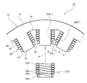
以下、本発明の実施形態を、図面に従って説明する。図1は、回転電機のステータ10の回転電機の軸線(以下、単に軸線と記す。)に直交する断面の一部を示す図である。ステータ10のコア12は、略円筒形状のヨーク部14と、ヨーク部14の内周面から円筒の軸線に向けて延びる磁極16を有する。磁極16は、ヨーク部14の内周面に周方向に沿って間隔をあけて配置される。磁極16の間の空間はスロット18と呼ばれる。スロット18内には、導線20が配置され、この導線20は一つの磁極16の周囲を回り、磁極16に巻き付いた導線20によりコイル22が形成されている。
Hereinafter, embodiments of the present invention will be described with reference to the drawings. FIG. 1 is a diagram showing a part of a cross section perpendicular to an axis of a rotating electrical machine (hereinafter simply referred to as an axis) of a
ステータコア12の軸線直交断面の形状は、軸線方向においてほぼ一定の形状である。磁極16は、根元から先端に向け、すなわち回転電機の半径方向の外側から内側に向け、ほぼ一定の幅aを有する。これに対し、スロット18は、半径方向の内側が狭くなっている。
The shape of the stator core 12 in the cross section perpendicular to the axis is substantially constant in the axial direction. The
コイル22は、磁極16に装着する以前に、図1中符号22Aで示すように巻回され、磁極16に装着された際の形状に形成されている。この巻回された状態で、図1中の矢印Aで示すように、磁極16に装着される。つまり、コイル22は、いわゆるカセットコイルである。
Before the
コイルを形成している導線20は、図示するように断面が長方形の、いわゆる平角線である。導線20は、磁極16に対して一重に巻回されている。コイル22Aにおいては、導線20が、図1中の上から下に向けて順次巻回されている。隣接する導線は、ほぼ隙間のない状態で詰めて巻回される。巻き始めにおいて、導線20は、断面の長方形の短辺が、磁極16の側面24、すなわちスロット18に向いた面に対向するように巻き付けられる。最後の周回になる前に、導線20は、一つのスロット18から隣のスロット18に移る間にひねられて、最後の周回において、長辺が磁極の側面24に対向するようにされて巻き付けられる。したがって、コイル22の導線20は、磁極16に装着されたとき、回転電機の最も内側の1周の導線20aが、長辺が磁極の側面24に対向する横向きの状態に、他の周の導線20bが、短辺が磁極の側面24に対向する縦向きの状態となっている。導線20を巻き付ける順序は限定されるものではなく、例えば、下から上へと巻かれてもよい。
The conducting
コイル22が磁極16に装着されたとき、隣接するコイル22が接触しないように、コイル22の間隔、すなわちスロットの幅が決定される。また、前述のように、コイル22は、予め所定の形状に巻回された後に、磁極16に挿入される。よって、挿入する時に隣接するコイル22同士が干渉しないように、コイル22間に所定の隙間を設ける必要がある。図1中にこの隙間gが示されている。隣接コイル間の隙間は、スロット18が回転電機の半径方向内側で狭くなっているため、内側に巻回された導線20の間隔で規定される。しかし、このコイル22においては、最も内側の導線20aは横向きとされており、このため縦向きの導線20bの最も内側に位置する導線20b-1の間隔が最も近接し、隣接コイル間の隙間gは、この導線20b-1の間隔で規定される。
When the
図2は、比較のために、平角線である導線50を、全ての周回において断面の短辺が磁極の側面52に対向するように巻き付けて形成されたコイル54の例を示す図である。隣接するコイル52間の必要な間隙gを確保するために、図1に示すステータ10に比較して、スロット56の幅を広くされ、その分磁極58の幅bが狭くされている。したがって、ステータ10は、コイル22の、回転電機の半径方向内側の導線20aを横向きに配置したことにより、スロットの幅を狭くし、占積率(スロット断面積に対する導線の総断面積の割合)を相対的に増加させている。また、スロットの幅が狭くされた分、磁極16の幅もbからaに広くされており、この結果、磁極16の、磁極を通る磁束に直交する断面積を増加させている。これにより、磁気飽和が発生する磁束を高くすることができる。
For comparison, FIG. 2 is a diagram showing an example of a
コイル22においては、最も内側の周の導線のみ横向きの配置としたが、内側の2周以上を横向きとすることもできる。また、コイル22においては、導線20は1層に巻いたが、これに重ねて多層に巻いてもよい。この場合、各層の最も内側の周の導線の全てを横向きに配置することもできるし、また一部の層の導線を横向きに配置することもできる。更に、導線を多層に巻く場合、回転電機の半径方向内側の層のうち下層、すなわち磁極に近い層の導線を横向きに配置してもよい。
In the
10 ステータ、12 ステータコア、16 磁極、18 スロット、20 導線、22 コイル、24 磁極側面。 10 stators, 12 stator cores, 16 magnetic poles, 18 slots, 20 conductors, 22 coils, 24 magnetic pole side surfaces.
Claims (1)
前記導線は長方形断面を有し、
磁極に装着された際の回転電機内側から1周または複数周の前記導線は、断面の長辺が磁極の表面に対向するように配置され、残りの導線は、断面の短辺が磁極の表面に対向するように配置される、
カセットコイル。 A cassette coil that is formed in a predetermined shape by winding a conducting wire a plurality of times in advance, and then attached to the magnetic pole of a rotating electrical machine,
The conducting wire has a rectangular cross section;
The conducting wire having one or more rounds from the inside of the rotating electrical machine when mounted on the magnetic pole is arranged so that the long side of the cross section faces the surface of the magnetic pole, and the remaining conducting wire has the short side of the cross section of the surface of the magnetic pole. Arranged to face the
Cassette coil.
Priority Applications (1)
| Application Number | Priority Date | Filing Date | Title |
|---|---|---|---|
| JP2011128121A JP2012257362A (en) | 2011-06-08 | 2011-06-08 | Cassette coil of rotary electric machine |
Applications Claiming Priority (1)
| Application Number | Priority Date | Filing Date | Title |
|---|---|---|---|
| JP2011128121A JP2012257362A (en) | 2011-06-08 | 2011-06-08 | Cassette coil of rotary electric machine |
Publications (1)
| Publication Number | Publication Date |
|---|---|
| JP2012257362A true JP2012257362A (en) | 2012-12-27 |
Family
ID=47528370
Family Applications (1)
| Application Number | Title | Priority Date | Filing Date |
|---|---|---|---|
| JP2011128121A Withdrawn JP2012257362A (en) | 2011-06-08 | 2011-06-08 | Cassette coil of rotary electric machine |
Country Status (1)
| Country | Link |
|---|---|
| JP (1) | JP2012257362A (en) |
Cited By (3)
| Publication number | Priority date | Publication date | Assignee | Title |
|---|---|---|---|---|
| JP2015119534A (en) * | 2013-12-17 | 2015-06-25 | スズキ株式会社 | Motor |
| JP2016149905A (en) * | 2015-02-13 | 2016-08-18 | マツダ株式会社 | Stator for rotary electric machine, and manufacturing method thereof |
| US9806573B2 (en) | 2012-08-03 | 2017-10-31 | Toyota Jidosha Kabushiki Kaisha | Stator for rotary electric motor |
-
2011
- 2011-06-08 JP JP2011128121A patent/JP2012257362A/en not_active Withdrawn
Cited By (3)
| Publication number | Priority date | Publication date | Assignee | Title |
|---|---|---|---|---|
| US9806573B2 (en) | 2012-08-03 | 2017-10-31 | Toyota Jidosha Kabushiki Kaisha | Stator for rotary electric motor |
| JP2015119534A (en) * | 2013-12-17 | 2015-06-25 | スズキ株式会社 | Motor |
| JP2016149905A (en) * | 2015-02-13 | 2016-08-18 | マツダ株式会社 | Stator for rotary electric machine, and manufacturing method thereof |
Similar Documents
| Publication | Publication Date | Title |
|---|---|---|
| JP5692247B2 (en) | Collective conductor for motor winding | |
| JP5693793B2 (en) | Rotating electric machine | |
| US20120274172A1 (en) | Stator for rotating electrical machine | |
| CN108141082B (en) | Rotating electrical machine | |
| US9438078B2 (en) | Arrangement of coil wires in a rotor of an electric motor | |
| JP5928452B2 (en) | motor | |
| US9590457B2 (en) | Stator of a rotary electric machine | |
| CN107078565A (en) | Stator for electric rotating machine | |
| US9716414B2 (en) | Stator of rotating electric machine | |
| JP2015527043A (en) | Coil and stator assembly for rotating electrical machines | |
| JP2012257362A (en) | Cassette coil of rotary electric machine | |
| JP2008187868A (en) | Rotary electric machine, and manufacturing method of field coil | |
| JP5271991B2 (en) | Rotating electric machine stator | |
| JP5884464B2 (en) | Rotating electric machine | |
| JP2010081670A (en) | Alternating current generator | |
| CN103368303A (en) | Low-noise alternating current motor and winding method thereof | |
| JP2013034350A (en) | Rotary electric machine stator | |
| JP2008035646A (en) | Magnetic-pole concentrated winding structure for stator | |
| JP6283451B1 (en) | Rotating electric machine | |
| CN104319915A (en) | Split type stator structure | |
| KR20160084694A (en) | Motor | |
| JP2015073379A (en) | Rotary electric machine stator | |
| JP5474039B2 (en) | Commutator motor for vacuum cleaner | |
| US20140354106A1 (en) | Reduction of leakage flux in electrical machines | |
| KR20160052931A (en) | Stator structure of hairpin winding motor |
Legal Events
| Date | Code | Title | Description |
|---|---|---|---|
| A300 | Withdrawal of application because of no request for examination |
Free format text: JAPANESE INTERMEDIATE CODE: A300 Effective date: 20140902 |