EP4339747A1 - Elektronischer stift und kernkörper für elektronischen stift - Google Patents
Elektronischer stift und kernkörper für elektronischen stift Download PDFInfo
- Publication number
- EP4339747A1 EP4339747A1 EP22807289.8A EP22807289A EP4339747A1 EP 4339747 A1 EP4339747 A1 EP 4339747A1 EP 22807289 A EP22807289 A EP 22807289A EP 4339747 A1 EP4339747 A1 EP 4339747A1
- Authority
- EP
- European Patent Office
- Prior art keywords
- core rod
- core body
- insertion hole
- protection member
- core
- Prior art date
- Legal status (The legal status is an assumption and is not a legal conclusion. Google has not performed a legal analysis and makes no representation as to the accuracy of the status listed.)
- Withdrawn
Links
Images


Classifications
-
- G—PHYSICS
- G06—COMPUTING OR CALCULATING; COUNTING
- G06F—ELECTRIC DIGITAL DATA PROCESSING
- G06F3/00—Input arrangements for transferring data to be processed into a form capable of being handled by the computer; Output arrangements for transferring data from processing unit to output unit, e.g. interface arrangements
- G06F3/01—Input arrangements or combined input and output arrangements for interaction between user and computer
- G06F3/03—Arrangements for converting the position or the displacement of a member into a coded form
- G06F3/033—Pointing devices displaced or positioned by the user, e.g. mice, trackballs, pens or joysticks; Accessories therefor
- G06F3/0354—Pointing devices displaced or positioned by the user, e.g. mice, trackballs, pens or joysticks; Accessories therefor with detection of two-dimensional [2D] relative movements between the device, or an operating part thereof, and a plane or surface, e.g. 2D mice, trackballs, pens or pucks
- G06F3/03545—Pens or stylus
-
- G—PHYSICS
- G06—COMPUTING OR CALCULATING; COUNTING
- G06F—ELECTRIC DIGITAL DATA PROCESSING
- G06F3/00—Input arrangements for transferring data to be processed into a form capable of being handled by the computer; Output arrangements for transferring data from processing unit to output unit, e.g. interface arrangements
- G06F3/01—Input arrangements or combined input and output arrangements for interaction between user and computer
- G06F3/03—Arrangements for converting the position or the displacement of a member into a coded form
- G06F3/041—Digitisers, e.g. for touch screens or touch pads, characterised by the transducing means
- G06F3/044—Digitisers, e.g. for touch screens or touch pads, characterised by the transducing means by capacitive means
- G06F3/0441—Digitisers, e.g. for touch screens or touch pads, characterised by the transducing means by capacitive means using active external devices, e.g. active pens, for receiving changes in electrical potential transmitted by the digitiser, e.g. tablet driving signals
-
- G—PHYSICS
- G06—COMPUTING OR CALCULATING; COUNTING
- G06F—ELECTRIC DIGITAL DATA PROCESSING
- G06F3/00—Input arrangements for transferring data to be processed into a form capable of being handled by the computer; Output arrangements for transferring data from processing unit to output unit, e.g. interface arrangements
- G06F3/01—Input arrangements or combined input and output arrangements for interaction between user and computer
- G06F3/03—Arrangements for converting the position or the displacement of a member into a coded form
- G06F3/033—Pointing devices displaced or positioned by the user, e.g. mice, trackballs, pens or joysticks; Accessories therefor
- G06F3/0354—Pointing devices displaced or positioned by the user, e.g. mice, trackballs, pens or joysticks; Accessories therefor with detection of two-dimensional [2D] relative movements between the device, or an operating part thereof, and a plane or surface, e.g. 2D mice, trackballs, pens or pucks
-
- G—PHYSICS
- G06—COMPUTING OR CALCULATING; COUNTING
- G06F—ELECTRIC DIGITAL DATA PROCESSING
- G06F3/00—Input arrangements for transferring data to be processed into a form capable of being handled by the computer; Output arrangements for transferring data from processing unit to output unit, e.g. interface arrangements
- G06F3/01—Input arrangements or combined input and output arrangements for interaction between user and computer
- G06F3/03—Arrangements for converting the position or the displacement of a member into a coded form
- G06F3/033—Pointing devices displaced or positioned by the user, e.g. mice, trackballs, pens or joysticks; Accessories therefor
- G06F3/038—Control and interface arrangements therefor, e.g. drivers or device-embedded control circuitry
- G06F3/0383—Signal control means within the pointing device
-
- G—PHYSICS
- G06—COMPUTING OR CALCULATING; COUNTING
- G06F—ELECTRIC DIGITAL DATA PROCESSING
- G06F3/00—Input arrangements for transferring data to be processed into a form capable of being handled by the computer; Output arrangements for transferring data from processing unit to output unit, e.g. interface arrangements
- G06F3/01—Input arrangements or combined input and output arrangements for interaction between user and computer
- G06F3/03—Arrangements for converting the position or the displacement of a member into a coded form
- G06F3/041—Digitisers, e.g. for touch screens or touch pads, characterised by the transducing means
- G06F3/044—Digitisers, e.g. for touch screens or touch pads, characterised by the transducing means by capacitive means
- G06F3/0442—Digitisers, e.g. for touch screens or touch pads, characterised by the transducing means by capacitive means using active external devices, e.g. active pens, for transmitting changes in electrical potential to be received by the digitiser
Definitions
- the invention relates to an electronic pen used as a position indicator for a position detection apparatus installed on an information processing apparatus, such as a tablet PC (Personal Computer), and to a core body for an electronic pen used in the electronic pen.
- an information processing apparatus such as a tablet PC (Personal Computer)
- a core body for an electronic pen used in the electronic pen such as a tablet PC (Personal Computer)
- a position detection apparatus and a position indicator are used as input devices of various types of electronic devices, such as a high-performance phone terminal called a smartphone and a tablet PC (Personal Computer).
- the position indicator is generally formed in a pen shape, and the position indicator is called an electronic pen, a stylus, or the like.
- position detection apparatuses and position indicators There are various types of position detection apparatuses and position indicators.
- AES Active Electrostatic
- a signal from an oscillation circuit installed on the electronic pen is transmitted (emitted) from a pen tip toward a position detection sensor of the position detection apparatus to indicate the position on the position detection sensor.
- the position detection sensor used in the position detection apparatus of active capacitance type includes linear transparent electrodes arranged on a display screen of a display apparatus, such as an LCD (Liquid Crystal Display), in an X-axis direction (horizontal direction) and a Y-axis direction (vertical direction) of the display screen.
- the position detection apparatus detects the position indicated by the electronic pen, according to the positions of the linear transparent electrodes of the position detection sensor that receive the signal (electric field) emitted from the electronic pen.
- the conventional core body of the electronic pen of active capacitance type is a columnar rod-shaped body, and the entire core body contains a conductive material.
- rippling occurs in the reception signal detected by the position detection apparatus, when the electronic pen is tilted to move the pen tip, and there is a problem that the linear characteristics of the detected indicated position are degraded. This is because the signal (electric field) from the signal generation circuit is emitted not only from the pen tip (front end portion) of the core body of the electronic pen, but also from an axis part of the core body.
- the signal (electric field) emitted from the axis part of the core body along with the movement of the electronic pen is received by the linear transparent electrodes of the position detection sensor.
- the received signal is strong when the axis part of the core body is over the transparent electrodes, and the received signal is weak when the axis part of the core body is out of the transparent electrodes.
- rippling occurs in the reception signal received by the transparent electrodes. This degrades the linear characteristics as detection characteristics of the indicated position when the electronic pen is tilted.
- a front end portion of the core body can be spherical and the axis part can be as thin as possible in the core body of the electronic pen of active capacitance type, as disclosed in Patent Document 1 described later.
- a core rod formed from a conductive material can have a shape becoming gradually narrower from the pen tip side toward the rear end side, and a protection member can cover the surroundings of the core rod to form the core body, as disclosed in Patent Document 2 described later.
- the conductive axis part is thin, and there is almost no influence of the signal (electric field) emitted from the axis part when the electronic pen is titled.
- the spherical pen tip is proactively involved in the emission of the signal (electric field), and the range of the reception signal is not enlarged. Therefore, excellent linear characteristics can be obtained.
- electrode parts at the front end and the rear end need to be connected to each other by the thin axis part, and injection processing needs to be executed with resin that covers the axis part. The manufacturing thus becomes difficult.
- the material of the core rod formed from the conductive material can be changed to a soft material to change the feel of writing.
- the strength of the core body is reduced, and therefore, the core rod containing the conductive material is wrapped up by the resin to reinforce the core rod.
- the core rod becomes gradually thinner toward the rear end side of the core rod. Therefore, sufficient strength needs to be maintained with use of, for example, the protection member to cover the rear end side of the core rod formed from the conductive material.
- the core body of the electronic pen is a part that directly comes in contact with an operation surface. The core body is thin and short with respect to the entire electronic pen, and a desirable strength is necessary. It is also desirable that the core body be easily manufactured.
- an object of the invention is to realize a core body for an electronic pen and an electronic pen with the core body in which detection characteristics of an indicated position and a tilt are favorable, sufficient strength is maintained, the configuration is simple, and manufacturing is easy.
- an electronic pen including a cylindrical housing including an opening portion on one end portion in an axial direction, a core body attached inside the housing such that a front end portion in the axial direction protrudes from the opening portion of the housing, and a signal generation circuit that generates a signal to be transmitted from the core body.
- the core body includes a core rod with conductivity that receives the signal from the signal generation circuit, and a protection member that covers the core rod.
- the core rod includes a pen tip portion on a front end side, an installation portion on a rear end side, and an axis portion that connects the pen tip portion and the installation portion.
- the core body includes a middle portion with a dielectric constant different from a dielectric constant of the protection member, the middle portion being provided around a side surface of the axis portion of the core rod in such a manner as to separate the core rod from the protection member.
- the electronic pen includes the housing, the core body, and the signal generation circuit.
- the core body is attached inside the housing such that the front end portion in the axial direction protrudes from the opening portion of the housing, and the signal generation circuit generates the signal to be transmitted from the core body.
- the core body includes the middle portion provided around the axis portion of the core rod and includes the protection member provided around the middle portion.
- the dielectric constant of the middle portion and the dielectric constant of the protection member are different. Therefore, two layers of capacitors are provided around the axis portion of the core rod. In this state, the signal (electric field) emitted from the axis portion of the core rod is suppressed, and this realizes the electronic pen with favorable characteristics of an indicated position and linearity.
- the electronic pen of the embodiment described below is of an active capacitance type that transmits a signal from the electronic pen side and that detects an indicated position according to the position on a position detection sensor that has received the signal.
- FIG. 1 is a diagram for describing a configuration example of an electronic pen 1 of the embodiment, and for the description, part of a case (housing) 2 of the electronic pen 1 is cut to illustrate the inside of the electronic pen 1.
- FIGS. 2A and 2B are diagrams for describing main parts of the electronic pen 1. Specifically, FIG. 2A is an enlarged cross-sectional view of main parts on the pen tip side of the electronic pen 1 which are not illustrated in FIG. 1 .
- FIG. 2B is a diagram in which parts for realizing functions of pen pressure detection and signal transmission in the electronic pen 1 are extracted and schematically illustrated.
- the electronic pen 1 includes the case (housing) 2 in a cylindrical shape elongated in an axial direction (a direction along the axial center).
- the case 2 contains a conductive material, which is anodized aluminum in the example, and includes a case body 21 in a cylindrical shape including a hollow portion inside and a front cap 22 and a rear cap 23 coupled to the case body 21.
- the front cap 22 and the rear cap 23 are fitted to the case body 21 to form the case 2.
- the front cap 22 is a cylindrical body including a through hole 22a in the axial direction as illustrated in FIG. 2A , and the external shape of the part on the pen tip side of the electronic pen 1 is a tapered shape with the outer diameter becoming gradually smaller toward the pen tip.
- An end portion on the pen tip side of the front cap 22 is an opening portion H of the through hole 22a.
- a board holder 3 for holding installed components, such as a printed board 8, and a battery 5 are housed in the hollow portion of the case 2 as illustrated in FIG. 1
- a core body holder (core body holding portion) 6 and pressure sensing components (pen pressure detection portions) 7 are also housed in the hollow portion of the case 2 as illustrated in FIG. 2A .
- a core body 4 is inserted into the through hole 22a through the opening portion H of the front cap 22 and attached to the core body holder 6 inside the case 2.
- the core body 4 can also be removed from the core body holder 6. That is, the core body 4 can be attached to and detached from the case 2.
- the core body 4 includes a core rod 41 formed from a conductive material and a protection member 42 formed from a non-conductive material, and the core body 4 is provided with a space (air layer) 43 between the core rod 41 and the protection member 42.
- the board holder 3 is formed from an insulating resin, such as a liquid crystal polymer, and when the board holder 3 is housed in the hollow portion of the case 2, a pressure sensing component holding portion 3a and a printed board mounting table portion 3b are continuous in the axial direction of the electronic pen 1 as illustrated in FIG. 2A .
- the pressure sensing component holding portion 3a has a cylindrical shape including a hollow portion that houses the pressure sensing components 7 (a plurality of components for pen pressure detection), and the outer diameter of the pressure sensing component holding portion 3a is smaller than the inner diameter of the through hole 22a of the front cap 22.
- the printed board mounting table portion 3b has a shape of a boat for mounting and holding the printed board 8, and specifically, the printed board mounting table portion 3b has a shape such that a cylindrical body is cut in substantially half in the axial direction.
- the pressure sensing component holding portion 3a of the board holder 3 is set on the core rod 41 side, and the entire pressure sensing component holding portion 3a and printed board mounting table portion 3b are housed in the case 2 to fix the board holder 3 and prevent the board holder 3 from moving.
- the core body holder 6 that holds the core body 4 is coupled to the pressure sensing component holding portion 3a of the board holder 3, and the pressure (pen pressure) mainly applied to the core rod 41 of the core body 4 is transmitted to the pressure sensing components 7 in the pressure sensing component holding portion 3a.
- a terminal conductor 51 is provided on an end portion of the printed board mounting table portion 3b of the board holder 3, on the opposite side of the pressure sensing component holding portion 3a.
- the terminal conductor 51 is brought into electrical contact with a positive-side terminal 5a of the battery 5 and electrically connected to a copper foil pattern of a power line of the printed board 8.
- a coil spring terminal 52 that contains a conductive metal and that is electrically connected to a negative-side terminal 5b of the battery 5 is provided on a portion of the rear cap 23 fitted to the case body 21.
- the battery 5 is inserted into the case 2 in such a manner as to connect the positive-side terminal 5a to the terminal conductor 51 as illustrated in FIG. 1 .
- the rear cap 23 is fitted to the case body 21 such that the coil spring terminal 52 presses the negative-side terminal 5b of the battery 5.
- the case body 21 containing a conductive material is electrically connected to an earth conductor of the printed board 8.
- the rear cap 23 and the case body 21 contain a conductive material, and therefore, the negative-side terminal 5b of the battery 5 is electrically connected to the earth conductor of the printed board 8 through the rear cap 23 and the case body 21.
- the positive-side terminal 5a of the battery 5 is connected to the copper foil pattern of the power line of the printed board 8 through the terminal conductor 51.
- the voltage of the battery 5 is supplied as a power supply voltage of a circuit formed on the printed board 8.
- a circuit unit including a signal generation circuit 8S, an IC (Integrated Circuit) 10, and peripheral circuit components around the IC 10 are provided on the printed board 8.
- the signal generation circuit 8S generates a signal to be transmitted from the core rod 41 of the electronic pen 1.
- the IC 10 is included in a control circuit that controls the transmission of the signal from the signal generation circuit 8S to the core rod 41.
- the peripheral circuit unit includes push switches (side switches) 11 and 12, and the push switches 11 and 12 are operated through operation portions 11a and 12a.
- a conductor terminal member 14 that connects the core rod 41 and the signal generation circuit 8S and a conductor terminal member 15 that transmits detection output of pen pressure from the pressure sensing components 7 are connected to the printed board 8.
- the core body 4 is fitted to the core body holder 6 containing a conductive material, through a conductive elastic member 9, and the core body 4 is coupled to and held by the core body holder 6, as illustrated in FIG. 2A .
- the core body holder 6 is fitted to a holding member 73 of the pressure sensing components 7 in the pressure sensing component holding portion 3a of the board holder 3, and the pressure (pen pressure) applied to the core body 4 is transmitted to the pressure sensing components 7.
- a coil spring 13 as an example of an elastic member containing a conductive material, such as a conductive metal, provided between the core body holder 6 and the board holder 3 always biases the core body holder 6 toward the core rod 41 with respect to the board holder 3.
- the coil spring 13, along with the conductor terminal member 14, is included in electrical connection members that transmit, to the core rod 41, the signal from the signal generation circuit 8S in which the transmission of the signal is controlled by the IC 10 arranged on the printed board 8. Therefore, a metal plate 13a is provided on an end portion on the pen tip side of the pressure sensing component holding portion 3a of the board holder 3, and the coil spring 13 and the conductor terminal member 14 are electrically connected to each other.
- the signal from the signal generation circuit 8S goes through the conductor terminal member 14, the metal plate 13a, the coil spring 13, the core body holder 6, and the core rod 41, in this order, and the signal is sent out from the core rod 41.
- the conductor terminal member 14, the coil spring 13, the metal plate 13a, the core body holder 6, and the core rod 41 are included in the electrical connection members, and a transmission route of the position indication signal from the signal generation circuit 8S of the printed board 8 is formed.
- a variable capacitor in which the capacitance changes according to the pen pressure applied to the core rod 41 is used for the pressure sensing components (pen pressure detection portions) 7 of the embodiment.
- the pressure sensing components 7 include a plurality of components including a dielectric 71, a terminal member 72, the holding member 73, a conductive member 74, and an elastic member 75 as illustrated in FIG. 2A .
- the terminal member 72 contains a conductive material, and the terminal member 72 is included in a first electrode of the variable capacitor including the pressure sensing components 7.
- the conductive member 74 contains, for example, conductive rubber, and the elastic member 75 includes a coil spring containing a conductive material.
- the conductive member 74 and the elastic member 75 are electrically connected to each other, and the conductive member 74 and the elastic member 75 are included in a second electrode of the variable capacitor.
- the capacitance of the variable capacitor formed between the terminal member 72 included in the first electrode and the conductive member 74 included in the second electrode changes according to the pressure applied to the core rod 41.
- the change in the capacitance of the variable capacitor is supplied from the pressure sensing components 7 to the IC 10 provided on the printed board 8, through the conductor terminal member 15, and the IC 10 detects the pen pressure.
- the core body 4 of the electronic pen 1 of the embodiment is installed on the core body holder 6 inside the case 2, and the core body 4 can move in the axial direction.
- the core body 4 is pushed toward the inside of the case 2 according to the pen pressure applied by the user to the core rod 41.
- the core rod 41 and the core body holder 6 press the pressure sensing components 7, and the pen pressure can be detected.
- the action of the coil spring 13 described above can return the core body holder 6 and the core body 4 to the initial state illustrated in FIG. 2A .
- the IC 10 of the electronic pen 1 performs control of transmitting, to the position detection sensor, a burst signal (position indication signal) for coordinate detection (position detection) corresponding to the signal from the signal generation circuit 8S.
- a burst signal position indication signal
- position detection position detection
- the position detection sensor side can detect the position indicated by the electronic pen 1 on the position detection sensor.
- the pressure sensing components 7 execute an operation of detecting the pen pressure on the basis of the capacitance in a period in which the burst signal is transmitted.
- the IC 10 transmits, from the core rod 41, an encoded signal, which is obtained by modulating the signal from the signal generation circuit 8S according to the detected pen pressure, and notifies the position detection sensor side of the pen pressure.
- the position detection sensor side can also detect the pen pressure applied to the core body 4 of the electronic pen 1.
- the electronic pen 1 of the embodiment realizes the function of indicating the position on the position detection sensor to the position detection sensor and detecting the pen pressure applied to the core rod 41, to notify the position detection sensor of the pen pressure.
- the electronic pen 1 of the embodiment is characterized in the configuration of the core body 4.
- the electronic pen 1 can maintain favorable linear characteristics regarding the position detection to allow the position detection sensor side to appropriately detect the indicated position.
- the core body 4 used in the electronic pen 1 of the embodiment has sufficient strength as a core body.
- the configuration of the core body 4 is simple, and the core body 4 can easily be manufactured.
- FIGS. 3A and 3B are diagrams for describing a configuration example of the core body 4 of the electronic pen 1.
- FIG. 3A is an external view of the protection member 42 of the core body 4
- FIG. 3B is an external view of the core rod 41 of the core body 4.
- the core body 4 of the embodiment includes two members including the core rod 41 ( FIG. 3B ) and the protection member 42 ( FIG. 3A ) as illustrated in FIG. 2A and as also illustrated in FIGS. 3A and 3B .
- the core rod 41 is a rod-shaped body with conductivity, and the core rod 41 has a columnar shape with parts of different thicknesses, except for a front end part.
- the core rod 41 is formed by, for example, a metal material. In the embodiment, stainless steel (SUS (Steel Special Use Stainless)) or brass is used to form the core rod 41.
- the core rod 41 includes three parts including a pen tip portion 41a, an axis portion 41b, and an installation portion 41c as illustrated in FIG. 3B .
- the pen tip portion 41a is a part formed in an oval shape (prolate sphere) on the front end part of the core rod 41, and the shape allows to efficiently emit the position indication signal toward the position detection sensor.
- the axis portion 41b is a part that connects the pen tip portion 41a and the installation portion 41c, and as illustrated in FIG. 3B , the axis portion 41b includes three parts including a front-side axis portion 41b1, a middle axis portion 41b2, and a rear-side axis portion 41b3.
- the rear-side axis portion 41b3 is included in a portion fitted to the protection member 42 described in detail later. Therefore, the rear-side axis portion 41b3 will be referred to as a fitting portion 41b3 below.
- the diameter of the part of the pen tip portion 41a with the largest width (hereinafter, referred to as a wide part) is L1 and that the diameter of the fitting portion 41b3 of the axis portion 41b is L2 as illustrated in FIG. 3B .
- the diameter L1 of the wide part of the pen tip portion 41a is shorter than the diameter L2 of the fitting portion 41b3 (L1 ⁇ L2).
- roulette processing is applied to a side surface of the fitting portion 41b3, at the part indicated by a symbol RT in FIG. 3B .
- the roulette processing is processing of fine ridges applied to metal, and the roulette processing is also called knurling. Knurling has an effect of a better grip, and this can prevent the core rod 41 from easily coming off from the protection member 42 when the core rod 41 is installed on the protection member 42, as described later.
- the diameter of the front-side axis portion 41b1 gradually increases from the pen tip side toward the rear end side.
- the diameter of the middle axis portion 41b2 gradually increases from the pen tip side toward the rear end side.
- a connection part of the front-side axis portion 41b1 and the middle axis portion 41b2 has a big change in diameter.
- the diameter of any part of the front-side axis portion 41b1 is shorter than the diameter L1 of the pen tip portion 41a.
- the diameter of any part of the middle axis portion 41b2 is shorter than the diameter L2 of the fitting portion 41b3.
- the diameter of the axis portion 41b gradually increases from the front end side toward the rear end side in the structure such that Lb1 ⁇ Lb2 ⁇ L2 holds, where Lb1 represents the diameter of the front-side axis portion 41b1 and Lb2 represents the diameter of the middle axis portion 41b2.
- the installation portion 41c is a part installed, through the conductive elastic member 9, on the core body holder 6 provided inside the electronic pen 1, as described with reference to FIGS. 2A and 2B . That is, the installation portion 41c of the core rod 41 can be pushed into a cup part of the core body holder 6 provided with the conductive elastic member 9, to thereby install the core body 4 on the electronic pen 1, and the installation portion 41c can be pulled out to remove the core body 4 from the electronic pen 1. That is, the core body 4 including the core rod 41 and the protection member 42 described later can be attached to and detached from the electronic pen 1 through the installation portion 41c of the core body 4.
- the protection member 42 that is another constituent member of the core body 4 covers side surfaces of the pen tip portion 41a and the axis portion 41b of the core rod 41 as illustrated in FIGS. 2A and 2B .
- the protection member 42 protects the core rod 41 and realizes a favorable feel of writing.
- the protection member 42 is formed from various types of resin materials, and the protection member 42 can be formed with use of, for example, polyamide, polycarbonate, modified polyphenylene ether, polybutylene terephthalate, polyacetal, and the like.
- polyacetal is used to form the protection member 42.
- the polyacetal is also called POM (polyoxymethylene).
- the protection member 42 includes a front end portion 42a in a tapered shape becoming gradually narrower toward the front end and an extension portion 42b extending from a rear end surface of the front end portion 42a to the rear end side.
- An insertion hole 42c in which a rear end surface of the extension portion 42b is an opening and into which the core rod 41 is inserted and installed, is provided inside the protection member 42 in a longitudinal direction.
- the center of the insertion hole 42c in the longitudinal direction coincides with the center (axial center) of the protection member 42 in the longitudinal direction.
- a length (full length) LY of the insertion hole 42c of the protection member 42 in the longitudinal direction coincides with a length LY from the front end of the pen tip portion 41a of the core rod 41 to a position slightly closer to the front side with respect to a rear end surface of the fitting portion 41b3 of the core rod 41 as illustrated in FIGS. 3A and 3B .
- the inner diameter at the position of the insertion hole 42c corresponding to the wide part of the pen tip portion 41a of the core rod 41 is the same as L1 or slightly shorter than L1
- the inner diameter at the position of the insertion hole 42c corresponding to the fitting portion 41b3 of the core rod 41 is the same as L2 or slightly shorter than L2.
- the insertion hole 42c is a hole portion without ridges on an inner wall surface thereof, and the shape of the insertion hole 42c becomes gradually narrower from the opening on the rear end side toward the front end. The core rod 41 can easily be inserted into the insertion hole 42c.
- the space (air layer) 43 is formed between the axis portion 41b of the core rod 41 and the inner wall surface of the insertion hole 42c as illustrated in FIGS. 2A and 2B .
- the insertion hole 42c of the protection member 42 becomes gradually narrower from the part with the diameter L2 on the rear end side toward the part with the diameter L1 on the front end side as described above and as also illustrated in FIG. 3A .
- the diameter of the fitting portion 41b3 is L2
- the diameter of the wide part of the pen tip portion 41a is L1 in the core rod 41. Therefore, the core rod 41 has a shape becoming gradually narrower from the fitting portion 41b3 toward the pen tip portion 41a.
- the diameter of any part of the front-side axis portion 41b1 is shorter than the diameter L1 of the wide part of the pen tip portion 41a, and the diameter of any part of the middle axis portion 41b2 is shorter than the diameter L2 of the fitting portion 41b3.
- the space (air layer) 43 as a middle portion is generated between side surfaces of the front-side axis portion 41b1 and the middle axis portion 41b2 of the core rod 41 and the inner wall surface of the insertion hole 42c of the protection member 42 as illustrated in FIGS. 2A and 2B . That is, there is provided a structure in which the space (air layer) 43 is provided around the front-side axis portion 41b1 and the middle axis portion 41b2 and in which the protection member 42 is provided outside the space 43. It can be considered that the space (air layer) 43 as well as the protection member 42 formed from polyacetal are dielectrics that are substances in which the dielectric properties are dominant over the conductivity, and the dielectric constants of the space 43 and the protection member 42 are different.
- the space (air layer) 43 is present around the front-side axis portion 41b1 and the middle axis portion 41b2 of the core rod 41, and the protection member 42 is present outside the space 43, as illustrated in FIG. 2A . Therefore, the front-side axis portion 41b1 and the middle axis portion 41b2 of the core rod 41 are surrounded by two layers including the space (air layer) 43 and the protection member 42 in the structure.
- two capacitors including a capacitor including the space (air layer) 43 as a dielectric and a capacitor including the polyacetal (protection member 42) as a dielectric are provided around the front-side axis portion 41b1 and the middle axis portion 41b2 of the core rod 41 in the structure.
- the air layer and the polyacetal have different dielectric constants, and therefore, two capacitors including dielectrics with different dielectric constants are provided.
- an inner wall surface of the protection member 42 and a side surface of the pen tip portion of the core rod 41 are in close contact with each other at the part on the front end side from the wide part of the pen tip portion 41a of the core rod 41. Therefore, there is no space, and only the front end portion 42a of the protection member 42 is present.
- one capacitor including the polyacetal (protection member 42) as a dielectric is provided at the part on the front end side from the wide part of the pen tip portion 41a of the core rod 41.
- the signal (electric field) emitted from the part on the front end side with respect to the wide part of the pen tip portion 41a of the core rod 41 is relatively efficiently emitted through only the protection member 42. Therefore, the signal (electric field) emitted through the part on the front end side with respect to the wide part of the pen tip portion 41a of the core rod 41 is large.
- the signal (electric field) emitted from the front-side axis portion 41b1 and the middle axis portion 41b2 of the core rod 41 is suppressed by two layers of capacitors including the space 43 and the protection member 42. Therefore, the signal (electric field) emitted through the front-side axis portion 41b1 and the middle axis portion 41b2 of the core rod 41 is small.
- the diameter of the front-side axis portion 41b1 of the core rod 41 is shorter than the diameter of the wide part of the pen tip portion 41a, and the emitted signal (electric field) can be smaller than the signal (electric field) emitted from the pen tip portion 41a.
- the signal (electric field) emitted through the part on the front end side with respect to the wide part of the pen tip portion 41a of the core rod 41 can be large, and the signal (electric field) emitted from the front-side axis portion 41b1 and the middle axis portion 41b2 of the core rod 41 can be small. In this way, the signal (electric field) leaked from the front-side axis portion 41b1 and the middle axis portion 41b2 of the core rod 41 can be suppressed. This can improve the linear characteristics as detection characteristics of the indicated position when the electronic pen 1 is tilted, and this can prevent the deviation of the position indicated by the electronic pen 1 on the position detection apparatus side.
- the core body is conventionally formed by injection molding, in which the core rod 41 is inserted into the mold and fixed on the fixed position and the polyacetal is injected into the mold to form the core body.
- the core body 4 of the embodiment can be formed by a press-fitting system, in which the core rod 41 and the protection member 42 are separately formed and the core rod 41 is inserted into the insertion hole 42c of the protection member 42. Therefore, the core body 4 itself can easily be manufactured.
- the core rod 41 and the protection member 42 can be formed by methods suitable for the core rod 41 and the protection member 42, respectively.
- the protection member 42 covers the pen tip portion 41a and the axis portion 41b of the core rod 41 in the core body 4 of the embodiment as described with reference to FIGS. 2A to 3B . Therefore, since the thickness of the axis portion 41b part and the extension portion 42b of the protection member 42 can be thickened, the diameter of the part of the core body 4 protruding from the opening portion H of the front cap 22 can be thickened. As a result, the strength of the extension portion 42b of the core body 4 and the axis portion 41b part of the core rod 41 can be strengthened as illustrated in FIGS. 1 and 2A .
- the interval between a side surface of the extension portion 42b of the protection member 42 and an inner wall surface of the front cap 22 is very small as illustrated in FIG. 2A . This can prevent most of the looseness of the core body 4 during writing, and this can protect the core body 4 even when force in a direction crossing the axial direction is applied to the front end portion 42a of the core body 4.
- the core body 4 can slide in the axial direction to allow appropriate detection of the pen pressure.
- a rear end surface 42T of the front end portion 42a of the protection member 42 and a front end surface 22T of the front cap 22 face each other at a little interval. Therefore, even if large force is applied to the front end portion 42a in the axial direction of the electronic pen 1 due to sudden application of large pen pressure or due to a drop of the electronic pen 1 from a desk to a floor, the rear end surface 42T of the front end portion 42a and the front end surface 22T of the front cap 22 come into contact with each other. As a result, the core body 4 is not pushed into the case 2 of the electronic pen 1 more than necessary, and this can prevent the inconvenience of damaging the pressure sensing components 7.
- the core body 4 of the embodiment described above is provided with the space (air layer) 43 as a middle portion around the axis portion 41b of the core rod 41 and is provided with the extension portion 42b of the protection member 42 around the space 43.
- the space 43 and the protection member 42 have different dielectric constants, and therefore, two layers of capacitors are provided around the axis portion 41b of the core rod 41. This can suppress the signal (electric field) emitted from the axis portion 41b of the core rod 41. As a result, an excessive electric field from the axis is suppressed, and this can realize the core body for the electronic pen with favorable characteristics of the indicated position and the linearity when the electronic pen is tilted.
- the configuration of the core body 4 is simple, and this can realize the core body for the electronic pen that can easily be manufactured. Therefore, the core body 4 of the embodiment can be used to realize the electronic pen with favorable detection characteristics of the indicated position and the tilt.
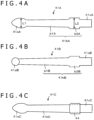
- FIGS. 4A to 4C are diagrams for describing other configuration examples of the core rod 41 of the core body 4.
- an axis portion 41bA that connects a pen tip portion 41aA and an installation portion 41cA may include a front-side axis portion b1A and a fitting portion b3A. That is, the axis portion 41bA is not separated into the front-side axis portion 41b1 and the middle axis portion 41b2, unlike in the axis portion 41b illustrated in FIGS. 2A to 3B , and the axis portion 41bA is a straight component with one stage.
- the axis portion of the core rod may be one-stage component except for the installation portion 41 cA as illustrated in FIG. 4A , may be a two-stage component except for the installation portion 41c as illustrated in FIGS. 2A to 3B , or may be a component with more than two stages.
- the core rod 41B includes a pen tip portion 41aB, an axis portion 41bB, and an installation portion 41cB
- the axis portion 41bB includes a front-side axis portion b1B and a fitting portion b3B.
- the shape of the pen tip portion 41aA is a spherical shape.
- the shape of the pen tip portion 41a of the core rod 41 is not limited to the oval shape, and the shape can be various types of shapes, such as a spherical shape, a cannonball shape with a dome-shaped front end, and an arrowhead shape with a sharpened front end, in consideration of the state of the emission of the signal (electric field).
- a pen tip portion 41aC, an axis portion 41bC, and an installation portion 41cC may be formed from a metal material in an integrated manner, and a fitting portion 44 may be formed as a separate component.
- the fitting portion 44 can also be formed from a metal material, a different material, such as hard rubber, may be used to form the fitting portion 44 into a cylindrical shape with some thickness. This is because the pen tip portion 41aC, the axis portion 41bC, and the installation portion 41cC of the core rod 41 C are formed from the metal material in an integrated manner and are conductive, so that the conductivity of the core rod 41C is not lost even when the fitting portion 44 is formed from a non-conductive material.
- the core rods 41A, 41B, and 41C described with reference to FIGS. 4A to 4C are examples, and there can be various other modifications.
- the core rod can have various types of shapes as long as the core rod is conductive from the front end to the rear end, and a middle portion, such as the space (air layer) 43, can be provided between the axial center part and the protection member 42 when the core rod is inserted into the insertion hole 42c of the protection member 42 and installed on the fixed position.
- FIGS. 5A to 5C are diagrams for describing other configuration examples of the protection member 42 of the core body 4.
- the resin material is used to form the protection member 42, and the protection member 42 is formed from polyacetal in the embodiment.
- the material is not limited to this.
- the protection member may also be formed with use of a technique called two-color molding (double molding) in which two types of resin materials are used to create one molded product.
- a protection member 42A ( FIG. 5A ), a protection member 42B ( FIG. 5B ), and a protection member 42C ( FIG. 5C ) illustrated in FIGS. 5A to 5C are formed to have shapes similar to the shape of the protection member 42 of the core body 4 illustrated in FIGS. 1 to 3B . That is, the protection members 42A, 42B, and 42C illustrated in FIGS. 5A to 5C include front end portions 42aA, 42aB, and 42aC, extension portions 42bA, 42bB, and 42bC, and insertion holes 42cA, 42cB, and 42cC, respectively, as in the protection member 42.
- two types of resin including polyacetal and elastomer are used, and the two-color molding technique is used to form the protection members 42A, 42B, and 42C.
- Most of the front end portion 42aA and the extension portion 42bA are formed from polyacetal in the protection member 42A illustrated in FIG. 5A , and a dome-shaped contact portion 42x formed from elastomer is provided on a frontmost part of the front end portion 42aA (a part in contact with an operation surface).
- the elastomer refers to a soft polymeric material that is elastic as rubber, and the softness, the elasticity, and other physical properties can be adjusted by the composition of the materials. In this way, a desirable feel of writing can be realized by providing the contact portion 42x containing elastomer on the front end portion 42aA.
- the feel of writing refers to conditions or writability in writing when the electronic pen is brought into contact with the operation surface to write, that is, a sense of touch transmitted to the hand of the user through the electronic pen. Therefore, by providing the contact portion 42x formed from elastomer, the electronic pen more softly comes in contact with the operation surface during writing, and the user can feel the sense of writing.
- the protection member 42A illustrated in FIG. 5A two layers of capacitors are formed by the front end side of the front end portion 42aA containing polyacetal and the contact portion 42x containing elastomer.
- the thickness of the contact portion 42x is thin, and there is a slight possibility that the signal (electric field) emitted from the contact portion 42x side is suppressed. Therefore, the thickness of a contact portion 42y of the front end portion 42aB is thickened as in the protection member 42B illustrated in FIG. 5B .
- the contact portion 42y formed from elastomer is on the pen tip side. This can prevent the suppression of the signal (electric field) emitted from the contact portion 42y side, and this can realize a desirable feel of writing.
- a part of the front end portion 42aC of the protection member 42C positioned on the front end side with respect to at least the wide part of the pen tip portion 41a of the core rod 41 is formed into a contact portion 42z containing elastomer. This can efficiently emit the signal (electric field) emitted from the pen tip portion 41a of the core rod 41 without significantly suppressing the signal, and this can realize a desirable feel of writing.
- protection members 42A, 42B, and 42C described with reference to FIGS. 5A to 5C are examples, and there can be various other modifications. In short, it is sufficient if the protection member is configured to emit the signal (electric field) from the pen tip portion of the core rod without attenuating the signal and is configured to emit the signal (electric field) from the axis portion of the core rod after attenuating the signal through the middle portion, such as the space (air layer), and the protection member.
- the contact portions 42x, 42y, and 42z attached to the front end by two-color molding may be conductive.
- a strong electric field can be emitted from the core body when the contact portions 42x, 42y, and 42z are conductive.
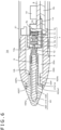
- FIG. 6 is a diagram for describing another configuration example of the electronic pen 1.
- the same reference symbols are provided to the parts with configurations similar to the configurations in the electronic pen 1 illustrated in FIGS. 2A and 2B , and the detailed description of these parts will not be repeated.
- the entire front end portion 42a of the protection member 42 of the core body 4 protrudes from the opening portion H of the front cap 22 of the case 2 as illustrated in FIGS. 1 , 2A, and 2B .
- the configuration is not limited to this.
- a core body 4X of an electronic pen 1A illustrated in FIG. 6 includes, for example, the core rod 41A illustrated in FIG. 4A and a protection member 42X, and a space (air layer) 43A is provided around an axis portion 41b1A of the core rod 41A.
- the protection member 42X is provided with a side surface part 42Xa1 in which the rear end side of a front end portion 42Xa is parallel to the axial center.
- the inside of the core body 4X can be similar to the inside of the core body 4 of the embodiment described above.
- an opening portion HA of a front cap 22A in the case of the electronic pen 1A illustrated in FIG. 6 is wider than the opening portion H of the front cap 22 of the electronic pen 1 illustrated in FIGS. 2A and 2B .
- the shape of the opening portion HA of the front cap 22A on the front end side is similar to the shape of a rear end surface 42XT of the protection member 42X
- the diameter of the opening portion HA on the front end side is slightly longer than the rear end surface 42XT of the front end portion 42Xa of the protection member 42.
- the side surface part 42Xa1 of the core body 4X on the rear end side of the front end portion 42Xa of the protection member 42X is fitted into the opening portion HA of the front cap 22A.
- the front cap 22A in the case of the electronic pen 1A illustrated in FIG. 6 is provided with a ring-shaped projection portion 22P projecting inside, at a position slightly lowered to the rear end side from the front end of the front cap 22A.
- a front end surface 22Px of the projection portion 22P faces the rear end surface 42XT of the front end portion 42Xa of the core body 4X.
- the core body 4X is pushed toward the rear end side when the pen pressure is applied to the core body 4X, and the core body 4X is pushed out to the original position when the pen pressure is released.
- the rear end surface 42XT of the front end portion 42Xa and the front end surface 22Px of the front cap 22A come into contact with each other even when large force in the axial direction is applied to the front end portion of the core body 4X due to sudden application of large pen pressure or a fall of the electronic pen 1A.
- the core body 4X is not pushed into the case (housing) of the electronic pen 1A more than necessary, and this can prevent the inconvenience of damaging the pressure sensing components 7.
- the side surface part 42Xa1 on the rear end side of the front end portion 42Xa of the protection member 42X faces an inner wall surface on the front end side of the opening portion HA of the front cap 22A.
- This can prevent most of the looseness of the core body 4X during writing, and this can protect the core body 4 even if force is applied to the front end portion 42Xa of the core body 4X in a direction crossing the axial direction.
- the interval between a side surface of an extension portion 42Xb of the core body 4X and an inner wall surface of the projection portion 22P of the front cap 22A can be reduced as much as possible to provide stronger strength to the core body 4X against the force in the direction crossing the axial direction.
- the projection portion 22P of the front cap 22A may be extended in the axial direction to broaden the area facing the side surface of the extension portion 42Xb of the core body 4X.
- FIGS. 7A to 7C and 8 are diagrams for describing another configuration example (core body 4Y) of the core body 4 of the electronic pen 1.
- the core body 4 described with reference to FIGS. 3A and 3B include two members including the protection member 42 and the core rod 41.
- the core body 4Y of the example includes three members including a front end member 45, an extension member 46, and the core rod 41.
- FIGS. 7A to 7C FIG. 7A is an external view of the front end member 45
- FIG. 7B is an external view of the extension member 46
- FIG. 7C is an external view of the core rod 41.
- the core rod 41 of the core body 4Y of the example is similar to the core rod 41 of the core body 4 described above. Therefore, the core rod 41 is provided with the same reference symbol as the reference symbol for the core rod 41 illustrated in FIG. 3C, and the description of the core rod 41 will not be repeated.
- the core rod 41 is formed from a metal material, and stainless steel (SUS (Steel Special Use Stainless)) or brass is also used to form the core rod 41 in the example.
- the front end member 45 and the extension member 46 are included in a part corresponding to the protection member 42 of the core body 4 described above with reference to FIGS. 3A and 3B .
- the front end member 45 has an appearance of a cone shape with a roundish front end part as illustrated in FIG. 7A .
- the front end member 45 is what is generally called a dome-shaped member including a large circular bottom-surface opening portion 45H provided on a bottom surface and including a space inside.
- a space on the front end portion side in the space provided inside the front end member 45 is a pen tip fitting portion 451 to which the pen tip portion 41a of the core rod 41 is fitted.
- a space on the bottom surface side in the space provided inside the front end member 45 is an extension member fitting portion 452 to which a front side part of the extension member 46 described later (a front-side tapered portion 461, a side-surface groove portion 46G, and a part on the front side of a middle portion 462) is fitted.
- an inner protrusion 452P is provided in a ring shape along the inner edge of the bottom-surface opening portion 45H.
- a part outside the bottom-surface opening 45H of the front end member 45 is a front end member rear end surface 45T with a thickness in a direction crossing (in the case of the example, a direction orthogonal to) the axial center (center axis of the core body 4Y).
- the front end member rear end surface 45T is a part facing the front end surface 22T of the front cap 22 of the case 2 when the core body 4Y of the example is installed on the electronic pen 1, as in the case in which the core body 4 illustrated in FIGS. 2A and 2B is used.
- the front end member 45 is formed from silicon rubber.
- the extension member 46 has a cylindrical shape (pipe shape) including a through hole formed in the axial direction (the same direction as the axial center) as illustrated in FIG. 7B .
- the extension member 46 includes a front-side opening portion 46FH on the front side (front end member 45 side) and a rear-side opening portion 46BH on the rear side.
- the extension member 46 includes three parts including, from the front side, the front-side tapered portion 461 in a tapered shape (shape becoming gradually narrower), the middle portion 462, and a rear-side portion 463 with the diameter slightly shorter than the diameter of the middle portion 462.
- the side-surface groove portion 46G is provided on a side surface (outer wall surface) of the extension member 46, at a boundary part of the front-side tapered portion 461 and the middle portion 462.
- the extension member 46 can be formed from a material similar to the material of the protection member 42 of the core body 4. Specifically, the extension member 46 can be formed from various types of resin materials, such as polyamide, polycarbonate, modified polyphenylene ether, polybutylene terephthalate, and polyacetal. In the embodiment, polyacetal is used to form the extension member 46. The polyacetal is also called POM (polyoxymethylene) as also described above.
- the shape of the extension member fitting portion 452 that is the space inside the front end member 45 and the shape of the front side part of the extension member 46 coincide with each other. Therefore, the front-side tapered part of the extension member 46 can be inserted and pushed into the bottom-surface opening portion 45H of the front end member 45 to join the front end member 45 and the extension member 46.
- an inner front end surface 452T of the extension member fitting portion 452 and a front end surface 461T of the extension member 46 come into contact with each other, and the inner protrusion 452P of the extension member fitting portion 452 of the front end member 45 is fitted in the side-surface groove portion 46G of the extension member 46.
- the inner wall surface of the extension member fitting portion 452 of the front end member 45 and a side surface (outer wall surface) of the front side part of the extension member 46 come in close contact with each other and do not easily come off.
- the outer shape and the inner shape of a joint member formed by joining the front end member 45 and the extension member 46 are similar to those of the protection member 42 illustrated in FIG. 3A .
- the front end member 45 is formed from silicon rubber and is elastic (resilient) and that the extension member 46 is a hard member formed from POM. Therefore, some force can be applied to pull them apart to thereby separate the joined front end member 45 and extension member 46. In this way, the front end member 45 and the extension member 46 can be attached to and detached from each other.
- the joint member provided by joining the front end member 45 and the extension member 46 is included in an insertion hole 47h into which the core rod 41 is inserted and installed in the longitudinal direction inside.
- the through hole 47h corresponds to the through hole 42c in the protection member 42 described with reference to FIG. 3A .
- the center in the longitudinal direction of the insertion hole 47h coincides with the center (axial center) in the longitudinal direction of the joint member including the front end member 45 and the extension member 46.
- the length (full length) in the longitudinal direction of the insertion hole 47h of the joint member coincides with the length LY from the front end of the pen tip portion 41a of the core rod 41 to the position slightly closer to the front side with respect to the rear end surface of the fitting portion 41b3 of the core rod 41 illustrated in FIG. 7C .
- the inner diameter of the insertion hole 47h of the j oint member at the position corresponding to the wide part of the pen tip portion 41a of the core rod 41 is the same as L1 or slightly shorter than L1
- the inner diameter of the insertion hole 47h at the position corresponding to the fitting portion 41b3 of the core rod 41 is the same as L2 or slightly shorter than L2.
- the insertion hole 47h does not include ridges on an inner wall surface thereof, and the insertion hole 47h is a hole portion in a shape becoming gradually narrower from the opening on the rear end side toward the front end. The core rod 41 can easily be inserted into the insertion hole 47h.
- the space (air layer) 43Y and the joint member including the front end member 45 formed from silicon rubber and the extension member 46 formed from polyacetal are dielectrics that are substances in which the dielectric properties are dominant over the conductivity.
- the dielectric constant of the space 43Y and the dielectric constant of the joint member (mainly the extension member 46) are also different. Therefore, the signal (electric field) emitted from the front-side axis portion 41b1 and the middle axis portion 41b2 of the core rod 41 is suppressed by two layers of capacitors including the space 43 and the joint member including the front end member 45 and the extension member 46 also in the case of the core body 4Y of the example.
- the signal (electric field) emitted through the front-side axis portion 41b1 and the middle axis portion 41b2 of the core rod 41 is small also in the case of the core body 4Y of the example. Further, the diameter of the front-side axis portion 41b1 of the core rod 41 is shorter than the diameter of the wide part of the pen tip portion 41a, and the emitted signal (electric field) can be smaller than the signal (electric field) emitted from the pen tip portion 41a.
- the signal (electric field) emitted through the part on the front end side with respect to the wide part of the pen tip portion 41a of the core rod 41 can be large, and the signal (electric field) emitted from the front-side axis portion 41b1 and the middle axis portion 41b2 of the core rod 41 can be small. In other words, the signal (electric field) leaked from the front-side axis portion 41b1 and the middle axis portion 41b2 of the core rod 41 can be suppressed.
- this can improve the linear characteristics as detection characteristics of the indicated position when the electronic pen 1 is tilted, and this can prevent the deviation of the position indicated by the electronic pen 1 on the position detection apparatus side.
- the core rod 41, the front end member 45, and the extension member 46 of the core body 4 of the example are separately formed.
- the front end member 45 and the extension member 46 are joined to form the joint member.
- the joint member corresponds to the protection member 42 of the core body 4 described with reference to FIGS. 3A and 3B .
- the core body 4Y can be formed by the press-fitting system, in which the core rod 41 is inserted into the insertion hole 47h of the joint member. Therefore, the core body 4Y itself can also easily be manufactured.
- the core rod 41, the front end member 45, and the extension member 46 can be formed by methods suitable for them, respectively.
- the front end member 45 is formed from an elastic member, such as silicon rubber, in the case of the core body 4Y of the example, and a softer feel of writing can be realized.
- the front end member 45 is formed from an elastic member, such as silicon rubber, the interval (gap) between the rear end surface 45T of the front end member 45 and the front end surface 22T of the front cap 22 of the case 2 of the electronic pen 1 can be narrowed. This is because, when the front end member 45 is formed from an elastic member, the core body 4Y can be pushed to some extent toward the rear end side even after the rear end surface 45T of the front end member 45 and the front end surface 22T of the front cap 22 come into contact with each other.
- the electronic pen is used by bringing the pen tip into contact with the operation surface, and therefore, the pen tip wears out by friction.
- the replacement of only the front end member 45 is easy in the core body 4Y including the front end member 45, the extension member 46, and the core rod 41. Therefore, only the front end member 45 needs to be replaced in the case of the core body 4Y, and this is economical compared to when the entire core body is replaced. That is, this can realize the core body 4Y for the electronic pen that can more economically be used.
- the space (air layer) 43 as a middle portion is provided between the axis portion 41b of the core rod 41 (the front-side axis portion 41b1 and the middle axis portion 41b2) and the extension portion 42b of the protection member 42 as illustrated in FIGS. 2A and 2B .
- the space (air layer) 43X as a middle portion is also provided between the axis portion 41b1A of the core rod 41A and the extension portion 42Xb of the protection member 42X in the core body 4X of the electronic pen illustrated in FIG. 6 .
- the space (air layer) 43Y as a middle portion is also formed between the axis portion 41b of the core rod 41 and the inner wall surface of the insertion hole 47h of the joint member including the front end member 45 and the extension member 46 in the case of the core body 4Y illustrated in FIGS. 7A to 7C and 8 .
- the middle portion is not limited to the space (air layer).
- various types of methods such as coating, vapor deposition, fusion, and winding, are used to apply a material with a dielectric constant different from the dielectric constant of the protection member 42 on the side surfaces of the front-side axis portion 41b1 and the middle axis portion 41b2 of the core rod 41, at a position similar to that of the space 43 and a thickness similar to that of the space 43.
- a middle portion containing a material different from the material of the protection member 42 can be provided on the side surfaces of the front-side axis portion 41b1 and the middle axis portion 41b2 of the core rod 41.
- the core rod 41 provided with the middle portion in this way is inserted into the insertion hole 42c of the protection member 42.
- the extension portion 42b of the protection member 42 can be positioned outside the middle portion, and the structure can be similar to the structure in which two layers of capacitors are formed around the front-side axis portion 41b1 and the middle axis portion 41b2.
- a middle portion containing a material with a dielectric constant different from the dielectric contact of the protection member 42X can be provided on the axis portion 41bA of the core rod 41A illustrated in FIG. 6 , and the middle portion can be inserted into the insertion hole of the protection member 42X to form the core body 4X.
- a material with a dielectric constant different from the dielectric constant of the front end member 45 or the extension member 46 may be supplied to provide a middle portion on the space (air layer) 43Y part.
- the middle portion provided on the core bodies 4, 4X, and 4Y is not limited to the space (air layer) 43.
- a material with a dielectric constant different from the dielectric constant of the protection members 42 and 42X can be used to form a middle portion, and this can provide the core body for the electronic pen with favorable detection characteristics of the indicated position and the tilt.
- the fitting portion 41 b3 is provided on the core rod 41 in the embodiment described above, the configuration is not limited to this.
- the fitting portion 41b3 may not be provided on the core rod 41, and the middle axis portion 41b2 may be extended to the fitting portion 41b3 part.
- a projection portion projecting inside is provided on a part corresponding to the protection member 42 or the extension member 46, that is, an opening portion part on the rear end side of the protection member 42 or the extension member 46, in place of the fitting portion 41b3 of the core rod 41.
- the projection portion of the protection member 42 or the extension member 46 and the rear end part of the middle axis portion 41b2 of the core rod 41 can be fitted to each other to fix the core rod 41 to the protection member 42 or the extension member 46.
- knurling may be applied to the rear end part of the middle axis portion 41b2 of the core rod 41 facing the projection portion of the protection member 42 or the extension member 46.
Landscapes
- Engineering & Computer Science (AREA)
- General Engineering & Computer Science (AREA)
- Theoretical Computer Science (AREA)
- Human Computer Interaction (AREA)
- Physics & Mathematics (AREA)
- General Physics & Mathematics (AREA)
- Position Input By Displaying (AREA)
Applications Claiming Priority (3)
| Application Number | Priority Date | Filing Date | Title |
|---|---|---|---|
| JP2021081590 | 2021-05-13 | ||
| JP2022063329 | 2022-04-06 | ||
| PCT/JP2022/017481 WO2022239585A1 (ja) | 2021-05-13 | 2022-04-11 | 電子ペンおよび電子ペン用の芯体 |
Publications (2)
| Publication Number | Publication Date |
|---|---|
| EP4339747A1 true EP4339747A1 (de) | 2024-03-20 |
| EP4339747A4 EP4339747A4 (de) | 2024-08-07 |
Family
ID=84028220
Family Applications (1)
| Application Number | Title | Priority Date | Filing Date |
|---|---|---|---|
| EP22807289.8A Withdrawn EP4339747A4 (de) | 2021-05-13 | 2022-04-11 | Elektronischer stift und kernkörper für elektronischen stift |
Country Status (5)
| Country | Link |
|---|---|
| US (2) | US12229352B2 (de) |
| EP (1) | EP4339747A4 (de) |
| JP (2) | JP7796732B2 (de) |
| KR (1) | KR20240006503A (de) |
| WO (1) | WO2022239585A1 (de) |
Families Citing this family (2)
| Publication number | Priority date | Publication date | Assignee | Title |
|---|---|---|---|---|
| WO2025037502A1 (ja) * | 2023-08-14 | 2025-02-20 | 株式会社ワコム | 電子ペン |
| WO2026014280A1 (ja) * | 2024-07-12 | 2026-01-15 | 株式会社ワコム | 電子ペン |
Family Cites Families (21)
| Publication number | Priority date | Publication date | Assignee | Title |
|---|---|---|---|---|
| US3673777A (en) * | 1970-09-03 | 1972-07-04 | Black & Decker Mfg Co | Blade mounting means |
| JP5534419B2 (ja) * | 2010-03-09 | 2014-07-02 | 株式会社ワコム | 位置指示器、可変容量コンデンサ及び入力装置 |
| WO2013179291A1 (en) * | 2012-05-31 | 2013-12-05 | N-Trig Ltd. | Writing tip for a stylus |
| JP6161498B2 (ja) | 2012-11-06 | 2017-07-12 | 東和化成株式会社 | 入力用タッチペンおよびその製造方法 |
| JP5667708B2 (ja) * | 2013-06-20 | 2015-02-12 | 株式会社ワコム | 位置指示器及び位置指示器の芯体 |
| US9298285B2 (en) * | 2013-12-05 | 2016-03-29 | Wacom Co., Ltd. | Stylus tip shape |
| CN105829997B (zh) | 2013-12-25 | 2019-05-17 | 株式会社和冠 | 位置指示用模块及触控笔 |
| US9239639B1 (en) * | 2014-06-24 | 2016-01-19 | Amazon Technologies, Inc. | Protecting stylus force sensor from excess force |
| JP5629032B1 (ja) * | 2014-06-27 | 2014-11-19 | 北星鉛筆株式会社 | 鉛筆用キャップ |
| CN106462261B (zh) * | 2014-07-08 | 2020-06-30 | 株式会社和冠 | 位置指示器 |
| JP5903131B2 (ja) | 2014-07-14 | 2016-04-13 | レノボ・シンガポール・プライベート・リミテッド | タッチペン及びそのペン先 |
| US9612671B1 (en) * | 2014-10-24 | 2017-04-04 | Amazon Technologies, Inc. | Stylus tip |
| US10198089B2 (en) * | 2015-09-08 | 2019-02-05 | Apple Inc. | Active stylus precision tip |
| JP6756525B2 (ja) * | 2016-06-16 | 2020-09-16 | 株式会社ワコム | 筆記具及び電子ペン本体部 |
| US10318022B2 (en) * | 2017-01-30 | 2019-06-11 | Microsoft Technology Licensing, Llc | Pressure sensitive stylus |
| JP3215060U (ja) * | 2017-12-13 | 2018-02-22 | 煥徳科技股▲ふん▼有限公司 | 導電性タッチペン先及びそれを使用したタッチペン |
| US20190220108A1 (en) * | 2018-01-15 | 2019-07-18 | Adonit Co., Ltd | Stylus having pen tip assembly and end cover synchronized in motion |
| CN110825246B (zh) * | 2018-08-07 | 2023-05-23 | 深圳普赢创新科技股份有限公司 | 侧压式位置指示装置 |
| WO2020054163A1 (ja) | 2018-09-13 | 2020-03-19 | 株式会社ワコム | 電子ペンおよび電子ペン用の芯体 |
| CN113227948B (zh) * | 2018-12-20 | 2024-06-04 | 株式会社和冠 | 静电电容方式的电子笔 |
| CN111837095B (zh) * | 2020-03-17 | 2024-07-26 | 深圳市汇顶科技股份有限公司 | 主动笔 |
-
2022
- 2022-04-11 EP EP22807289.8A patent/EP4339747A4/de not_active Withdrawn
- 2022-04-11 JP JP2023520927A patent/JP7796732B2/ja active Active
- 2022-04-11 WO PCT/JP2022/017481 patent/WO2022239585A1/ja not_active Ceased
- 2022-04-11 KR KR1020237033775A patent/KR20240006503A/ko active Pending
-
2023
- 2023-10-23 US US18/492,604 patent/US12229352B2/en active Active
-
2025
- 2025-01-15 US US19/023,110 patent/US20250155995A1/en active Pending
- 2025-12-23 JP JP2025277563A patent/JP2026040593A/ja active Pending
Also Published As
| Publication number | Publication date |
|---|---|
| US20250155995A1 (en) | 2025-05-15 |
| WO2022239585A1 (ja) | 2022-11-17 |
| EP4339747A4 (de) | 2024-08-07 |
| JP7796732B2 (ja) | 2026-01-09 |
| KR20240006503A (ko) | 2024-01-15 |
| JP2026040593A (ja) | 2026-03-09 |
| US12229352B2 (en) | 2025-02-18 |
| JPWO2022239585A1 (de) | 2022-11-17 |
| US20240053836A1 (en) | 2024-02-15 |
Similar Documents
| Publication | Publication Date | Title |
|---|---|---|
| US10372241B2 (en) | Position indicator | |
| US20250155995A1 (en) | Electronic pen and core body for electronic pen | |
| US12216845B2 (en) | Electronic pen and electronic pen body portion | |
| JP6370171B2 (ja) | 位置指示器 | |
| US20190171303A1 (en) | Position pointing device and core body for position pointing device | |
| CN108292174B (zh) | 电子笔 | |
| US11977690B2 (en) | Electronic pen and core body for electronic pen including conductive core rod and protection member that covers core rod | |
| JP7366067B2 (ja) | 静電結合方式の電子ペン | |
| US11465436B2 (en) | Position indicator | |
| US20250224819A1 (en) | Electronic pen | |
| WO2015115262A1 (ja) | 位置指示器及び位置検出装置 | |
| US12461609B2 (en) | Electronic pen | |
| JP2023005972A (ja) | 電子ペン及び電子ペン用芯体 | |
| CN108008847B (zh) | 主动式电容笔及其压力传感器 | |
| CN112236656B (zh) | 压力检测元件 | |
| JPWO2017110338A1 (ja) | 電子ペン | |
| CN117043724A (zh) | 电子笔及电子笔用的芯体 | |
| JP2022171167A (ja) | 電子ペン用芯体及び電子ペン本体部 | |
| JP2009130135A (ja) | 可変容量コンデンサ、位置指示器及び座標入力装置 | |
| CN117539358A (zh) | 电子笔 |
Legal Events
| Date | Code | Title | Description |
|---|---|---|---|
| STAA | Information on the status of an ep patent application or granted ep patent |
Free format text: STATUS: THE INTERNATIONAL PUBLICATION HAS BEEN MADE |
|
| PUAI | Public reference made under article 153(3) epc to a published international application that has entered the european phase |
Free format text: ORIGINAL CODE: 0009012 |
|
| STAA | Information on the status of an ep patent application or granted ep patent |
Free format text: STATUS: REQUEST FOR EXAMINATION WAS MADE |
|
| 17P | Request for examination filed |
Effective date: 20231019 |
|
| AK | Designated contracting states |
Kind code of ref document: A1 Designated state(s): AL AT BE BG CH CY CZ DE DK EE ES FI FR GB GR HR HU IE IS IT LI LT LU LV MC MK MT NL NO PL PT RO RS SE SI SK SM TR |
|
| REG | Reference to a national code |
Ref country code: DE Ref legal event code: R079 Free format text: PREVIOUS MAIN CLASS: G06F0003030000 Ipc: G06F0003035400 |
|
| A4 | Supplementary search report drawn up and despatched |
Effective date: 20240709 |
|
| RIC1 | Information provided on ipc code assigned before grant |
Ipc: G06F 3/044 20060101ALI20240703BHEP Ipc: G06F 3/038 20130101ALI20240703BHEP Ipc: G06F 3/0354 20130101AFI20240703BHEP |
|
| DAV | Request for validation of the european patent (deleted) | ||
| DAX | Request for extension of the european patent (deleted) | ||
| STAA | Information on the status of an ep patent application or granted ep patent |
Free format text: STATUS: THE APPLICATION HAS BEEN WITHDRAWN |
|
| 18W | Application withdrawn |
Effective date: 20250224 |