EP4339499A1 - Dispositif de protection et procédé - Google Patents
Dispositif de protection et procédé Download PDFInfo
- Publication number
- EP4339499A1 EP4339499A1 EP22196172.5A EP22196172A EP4339499A1 EP 4339499 A1 EP4339499 A1 EP 4339499A1 EP 22196172 A EP22196172 A EP 22196172A EP 4339499 A1 EP4339499 A1 EP 4339499A1
- Authority
- EP
- European Patent Office
- Prior art keywords
- shells
- protection device
- locking element
- cylindrical body
- locking
- Prior art date
- Legal status (The legal status is an assumption and is not a legal conclusion. Google has not performed a legal analysis and makes no representation as to the accuracy of the status listed.)
- Pending
Links
- 238000000034 method Methods 0.000 title claims description 10
- 229910052751 metal Inorganic materials 0.000 claims description 7
- 239000002184 metal Substances 0.000 claims description 5
- 210000002105 tongue Anatomy 0.000 description 9
- 239000000463 material Substances 0.000 description 6
- 238000004519 manufacturing process Methods 0.000 description 4
- 230000008901 benefit Effects 0.000 description 3
- 238000005299 abrasion Methods 0.000 description 2
- 230000001419 dependent effect Effects 0.000 description 2
- 238000009434 installation Methods 0.000 description 2
- 230000007246 mechanism Effects 0.000 description 2
- 230000009467 reduction Effects 0.000 description 2
- 238000004458 analytical method Methods 0.000 description 1
- 230000001934 delay Effects 0.000 description 1
- 238000009863 impact test Methods 0.000 description 1
- 239000011295 pitch Substances 0.000 description 1
- 238000003825 pressing Methods 0.000 description 1
- 230000008569 process Effects 0.000 description 1
- 230000001681 protective effect Effects 0.000 description 1
- 239000013585 weight reducing agent Substances 0.000 description 1
Images


Classifications
-
- F—MECHANICAL ENGINEERING; LIGHTING; HEATING; WEAPONS; BLASTING
- F16—ENGINEERING ELEMENTS AND UNITS; GENERAL MEASURES FOR PRODUCING AND MAINTAINING EFFECTIVE FUNCTIONING OF MACHINES OR INSTALLATIONS; THERMAL INSULATION IN GENERAL
- F16L—PIPES; JOINTS OR FITTINGS FOR PIPES; SUPPORTS FOR PIPES, CABLES OR PROTECTIVE TUBING; MEANS FOR THERMAL INSULATION IN GENERAL
- F16L57/00—Protection of pipes or objects of similar shape against external or internal damage or wear
- F16L57/06—Protection of pipes or objects of similar shape against external or internal damage or wear against wear
-
- F—MECHANICAL ENGINEERING; LIGHTING; HEATING; WEAPONS; BLASTING
- F16—ENGINEERING ELEMENTS AND UNITS; GENERAL MEASURES FOR PRODUCING AND MAINTAINING EFFECTIVE FUNCTIONING OF MACHINES OR INSTALLATIONS; THERMAL INSULATION IN GENERAL
- F16J—PISTONS; CYLINDERS; SEALINGS
- F16J3/00—Diaphragms; Bellows; Bellows pistons
- F16J3/04—Bellows
- F16J3/041—Non-metallic bellows
- F16J3/043—Non-metallic bellows with particular means for limiting wear
-
- H—ELECTRICITY
- H02—GENERATION; CONVERSION OR DISTRIBUTION OF ELECTRIC POWER
- H02G—INSTALLATION OF ELECTRIC CABLES OR LINES, OR OF COMBINED OPTICAL AND ELECTRIC CABLES OR LINES
- H02G3/00—Installations of electric cables or lines or protective tubing therefor in or on buildings, equivalent structures or vehicles
- H02G3/02—Details
- H02G3/04—Protective tubing or conduits, e.g. cable ladders or cable troughs
- H02G3/0462—Tubings, i.e. having a closed section
- H02G3/0468—Corrugated
-
- H—ELECTRICITY
- H02—GENERATION; CONVERSION OR DISTRIBUTION OF ELECTRIC POWER
- H02G—INSTALLATION OF ELECTRIC CABLES OR LINES, OR OF COMBINED OPTICAL AND ELECTRIC CABLES OR LINES
- H02G3/00—Installations of electric cables or lines or protective tubing therefor in or on buildings, equivalent structures or vehicles
- H02G3/02—Details
- H02G3/06—Joints for connecting lengths of protective tubing or channels, to each other or to casings, e.g. to distribution boxes; Ensuring electrical continuity in the joint
Definitions
- the present invention relates to a protection device, a use of a half-shell and/or a locking element in a protection device, and a method for assembling such a protection device.
- Protection devices for cylindrical bodies, in particular for pipes, hoses, cables, etc. are generally known in the prior art.
- Such protective devices may be arranged at critical points of such a cylindrical body, e.g. a corrugated hose for cables on machines.
- Such a machine may be for example a robot and the protection device is used to prevent damages to the hose by chafing or rubbing at such critical points where it may come into contact with moving parts, e.g. a swing arm, an arm or a hand.
- moving parts e.g. a swing arm, an arm or a hand.
- Such protection devices may be used in other industrial fields and processes.
- the protection devices usually consist of two parts that are joined together by separate means, for example, metal screws, clamps clips, etc. Therefore, the assembling of such protection devices may be difficult and time consuming. Furthermore, a subsequent repositioning is only possible with considerable effort.
- the separate means which is mostly made of metal, can damage the machine since they are not made of plastic like the cylindrical body
- an object of the present invention to provide a protection device for protecting cylindrical bodies from abrasions and which is easier to assemble. It is in particular an object of the present invention to provide a protection device which allows to be connected to a cylindrical body without any additional means, like screws or clamps.
- a protection device for protecting a cylindrical body comprising: at least two half-shells configured to be arranged on an external surface of the cylindrical body, wherein the two half-shells each comprise at least one cut-out; and at least one locking element configured to be arranged in the at least one cut-out of each half-shell for connecting the two half-shells and locking the protection device in an assembled state in an axial direction by forming a form- and/or a force fit with the cylindrical body.
- the protection device may be used with a cylindrical body or cylindrical element, like pipes, hoses, cables or similar structures.
- the cylindrical body may be flexible.
- the cylindrical body may have a textured, smooth or a corrugated surface.
- the cylindrical body may also be described as a cylindrical conduit.
- the protection device comprises at least three parts. More precisely, the protection device comprises at least two half-shells and at least one locking element. In a preferred embodiment, the protection device may comprise four parts. More precisely, the protection device may comprise two identical half-shells and two identical locking elements.
- the half-shells are configured to be arranged on a circumference of the cylindrical body in an assembled/installed state.
- the protection device may be adjacent and/or in contact with an outer surface of the cylindrical body.
- the two half-shells are preferably semi-circular. Other shapes may be possible.
- the half-shells each comprise at least one cut-out. In an assembled/installed state, the cut-out allows access to an outer surface of the cylindrical body so that the locking element may be arranged.
- the at least one locking element connects the two half-shells with each other.
- the locking element is arranged in the cut-out of each half-shell.
- the locking element further locks the protection device in an axial direction of the cylindrical body on which the protection device is arranged by forming a form- and/or force fit with the external surface of the cylindrical body.
- the locking element has two functions.
- the locking element may be interchangeable. This means, that different locking elements can be used with the same half-shells, depending on the surface of the cylindrical body. For example, a locking element for a cylindrical body with a corrugated surface may be different from a locking element for a cylindrical body with a smooth surface.
- the axial direction is the direction orthogonal to the radial direction of the half-shells or the cylindrical body.
- the axial direction is to be understood as the longitudinal direction of the cylindrical body.
- the protection device according to the present invention allows to be arranged on a designated position on a cylindrical body without additional separate connection means, for example, screws, clamps, clips etc. Furthermore, the assembly and/or disassembly of the protection device according to the present invention is easy and time-saving.
- the protection device according to the present invention has therefore a modular feature and may be easily configured for different applications.
- the area of application of the protection device may cover corrugated tubes with different pitches, hoses with smooth surfaces, over-extruded corrugated tubes, cables or components with similar external contours, etc.
- the same basic components half-shells are used for each application and specified for the respective application with the aid of the corresponding insert (locking element).
- the protection device according to the present invention or protection sleeve includes several technical advantages.
- the protection device according to the present invention has less volume and therefore less weight than prior art protection devices. Because the present protection device is lighter, the cylindrical body, for example a corrugated tube, is weighed down less, which is important, for example in the field of robotics/automation but also in other industrial fields.
- the protection device may be designed without any metallic components. This allows the protection device to cushion instead of break in case of a blow or strike. Additionally, the weight of the metal screws is also eliminated, which contributes to an additional weight reduction. Furthermore, a thinner wall thickness is possible, which leads to a further reduction in weight, material savings as well as faster production time.
- the protection device according to the present invention has a greater flexibility, which has been proven by laboratory analyses. Increased flexibility delays fracture during use, which is important since many movements and impacts occur in the field, for example during an industrial process. If the component is too stiff, it will break more quickly due to an impact, as no cushioning is possible.
- the protection device according to the present invention comprises a locking element instead of a screw, and therefore allows a cushioning against impacts.
- the locking element is configured to form a form-fit with a cylindrical body which is at least partially corrugated.
- a corrugated surface is very suitable for a form-fit connection, especially in an axial direction of the cylindrical body. Therefore, this embodiment provides an implementable solution to connect the protection device with such a cylindrical body.
- the half-shells each comprise two cut-outs and the half-shells are connected to each other by at least one locking element, in particular two locking elements, arranged in the cut-outs.
- the two locking elements provide a form closure and/or force fitting of the two half-shells. It also provides a fixation of the protection device in an axial direction of the cylindrical body.
- the half-shells each comprise at least one connection element at a free end of the half-shells.
- the free ends are located in a circumferential direction of the half-shells.
- the connection element provides a means for connecting the two half-shells, so that the half-shells stay in place during the installation.
- the at least one connection element may help that the two half-shells stay in place until the locking element is arranged in the cut-out and/or the protection device is arranged on its designated position.
- the connection elements may further provide a means for aligning the half-shells in a correct and easy manner.
- connection element comprises a dovetail joint and/or a pin-receptacle connection or pin-receptacle centering.
- the dovetail joint helps to preassemble the two half shells with each other, the half shells hold together by a form fit.
- the pin-receptacle centers the half shells and prevents the half shells from moving relatively to each other.
- the connection element comprises both elements. These two connection means allow a connection between the two half-shells without fixating the two half-shells with the cylindrical body. In other words, the two half-shells may still be moved in an axial direction of the cylindrical body to position the protection device.
- the half-shells are at least partially or completely identical to each other.
- the protection device comprises two half shells and two locking elements, wherein the two half shells and the two locking elements are identical to each other.
- the locking element is connected to the half-shells by a first latching element.
- the first latching element provides a means for connecting the locking element with the two half-shells by form fit.
- the first latching element may therefore be provided in the region of the cut-outs of the half-shells.
- the locking element may preferably be connected with each half-shell by means of the latching mechanism.
- the latching mechanism provides a connection means without any additional separate means, for example, like screw, clamps, clips, etc.
- the locking element comprises a fastening element for fastening the protection device to the cylindrical body in an assembled state.
- fastening elements for fastening the protection device to the cylindrical body in an assembled state.
- fastening elements for example, press-on means, like brackets and jaws, or form- fitting means, like protrusions and undercuts.
- the fastening element comprises ribs that are arranged opposite each other at axial ends of the locking element configured to be arranged in the cut-out of the half-shells in an assembled state.
- the axial direction of the locking element corresponds with the axial direction of the cylindrical body in an assembled state.
- the ribs may protrude towards the cylindrical body.
- the free ends of the ribs may correspond with an outer surface of the cylindrical body.
- the ribs extend and interact with the corrugated surface of the cylindrical body so that a form fit in an axial direction may be provided.
- the ribs on one side are spaced by a gap, in particular by a tapered gab.
- the gap may allow to connect the locking element with the two half-shells in an easier way.
- the brace elements of the half shells are arranged in the gap.
- a slit is formed between the locking element and a half-shell, in particular in the region of the gap.
- the slit my provide a means to disassemble the locking element and the two half-shells.
- the slit may be used to accommodate a screwdriver to lift out the locking element. Alternatively, any other tool, which may be suitable, can be used.
- the half-shells each comprise at least a secondary latching connection for connecting the locking element and the half-shells.
- the secondary latching element allows a pre-assembly of the protection device.
- the secondary latching connection allows to connect the locking element with the two half-shells, wherein it is still possible to move the protection device in an axial direction of the cylindrical body.
- the secondary latching connection is a temporary connection, until the protection device is moved into its designated position. When the protection device is in its designated or final position, the locking element can be connected with the two half-shells by the first latching connection by pressing down the locking element.
- the two half shells and the locking element do not comprise any metal parts and are connected without any additional elements, in particular metallic elements like screws or clamps.
- the protection device may be made entirely of a plastic material. This allows for less material and a lighter weight. Furthermore, this allows the protection device to cushion strikes and blows without breaking.
- a further aspect of the present invention is directed to a use of a half-shell and/or a locking element in a protection device according to one of the preceding embodiments.
- a further aspect of the present disclosure is directed to a method for assembling a protection device according to any one of the preceding embodiments, comprising the following steps:
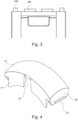
- Fig. 1 shows a half-shell 12 of a protection device 10 according to the present invention.
- the half shell 12 is configured to be arranged at a cylindrical body 11.
- the half-shell 12 comprises two web elements 21.
- the two web elements 21 have a semi-circular geometry and are parallel to each other.
- the two web elements 21 are connected by a bridge element 22.
- the bridge element 22 extends in the circumferential direction of the web elements 21.
- the bridge element 22 extends between the web elements 21. More precisely, the bridge element 22 is located in a middle area of the two web elements 21 in circumferential direction.
- the bridge element 22 is flush with the web elements 21 on an outer surface of the half-shell 12. In particular, the complete outer surface of the web elements 21 and the bridge element 22 of the half-shells 12 are flush.
- the bridge element 22 is not flush with the inner surface of the web elements 21.
- the bridge element 22 and the web elements 21 form steps on an inner surface of the half-shell 12. In other words, the bridge element 22 does not extend in the complete radial direction of the web elements 21.
- the inner surface of the web elements 21 is in contract with the outer surface of the cylindrical body 11 in an assembled state.
- the outer surface of the web elements 21 and the bridge element 22 of the half-shells 12 are at least partially rounded. More precisely, the web elements 21 and the bridge element 22 have convex geometries.
- the term convex is to be understood here as being curved or bent away from the central longitudinal axis of the cylindrical body 11 when assembled.
- Brace elements 23 are arranged in the areas of the ends in circumferential direction of the web elements 21. Each brace element 23 extends from one web element 21 to the other web element 21 and connects the two web elements 21. The brace elements 23 each have the form of an arched web.
- the half-shells 12 comprise two cut-outs 13.
- the cut-outs 13 are arranged between the brace elements 23, the bridge element 22 and the web elements 21.
- the cut-outs 13 each have a rectangular shape. Other shapes may be possible.
- Fig. 2 shows a detailed view of a free end in circumferential direction of the half-shell 12 and the brace element 23.
- Two connection elements 15 are arranged at the brace element 23.
- the shown half-shell 12 comprises two different kinds of connection elements 15.
- the connection elements 15 are further shown in Fig. 3 in more detail.
- One connection element 15 is a dovetail connection 15a and the other connection element 15 is a pin-receptacle connection 15b or centering.
- the dovetail connection 15a provides easier assembly, by holding the half shells together by form closure.
- the pin-receptacle connection 15b or centering prevent an unwanted movement of the half shells, for example in axial direction.
- a first latching element 16 and a secondary latching element 20 are located at each of the ends in circumferential direction of the bridge elements 22.
- the first latching element 16 comprises two protrusions on an inner surface of the bridge element 22.
- the two protrusions are equally spaced from the web elements 21.
- the secondary latching element 20 comprises a recess in the front side of the bridge element 22 in circumferential direction. Therefore, the secondary latching elements 20 are closer to the outer surface of the locking element 14 in an assembled state. It is possible, that the protection device 10 may only comprise the first latching elements 16.
- the first and secondary latching elements 16, 20 interact with a corresponding latching element 24 on a locking element 14.
- the locking element 14 is shown in detail in Fig. 4 and Fig. 5 .
- the locking element 14 has an arched form.
- the locking element 14 further has a convex wall or surface, in particular the outer and inner surface is bend outwards, in particular away from a longitudinal axis of the protection device 10, in an assembled state.
- the locking element 14 comprises ribs 17.
- the ribs 17 are arranged at the axial ends of the locking element 14. More precisely, the locking element 14 comprises two ribs 17 on each axial end.
- the axial direction is the direction orthogonal to the radius of the semi-circular half-shells 12.
- the ribs 17 protrude away from the convex wall towards the cylindrical body 11 in an assembled state.
- the geometry of the free ends of the ribs 17 correspond to the cylindrical body 11.
- the ribs 17 are configured to interact with a corrugated surface of the cylindrical body 11 to allow a form fit in axial direction of the cylindrical body 11.
- the ribs 17 are an embodiment of fastening elements of the protection device 10.
- the ribs 17 are not distributed over 360°, but over -40° on two snaps. This means in total 80°, by this reduction, it is possible for the half-shell 12 to cushion instead of break in case of a blow or strike. This was proven by means of impact tests.
- a gap 18 is located between the two ribs 17, which are located on the same axial end. More precisely, the gap 18 is positioned in the middle of the locking element 14 in circumferential direction.
- the gap 18 is tapered but may have any other suitable shape.
- the locking element 14 comprises a tongue 25 on each free end in circumferential direction.
- the tongues 25 extend along the free ends of the locking element 14 in a direction parallel to the longitudinal axis of the cylindrical body 11 in an assembled state.
- the tongues 25 extend along the complete length of the free ends.
- Other embodiments may be possible.
- the tongues 25 extend into the same direction as the ribs 17. In other words, the tongues 25 extend/protrude towards the cylindrical body in an assembled state.
- the tongues 25 of the locking element 14 comprise each a corresponding latching element 24.
- the corresponding latching element 24 is arranged at an outer surface of the tongues 25. The outer surfaces face into the circumferential direction of the locking element 14.
- the corresponding latching element 24 is formed as an edge, which protrudes away from the tongue 25. Alternatively, other suitable forms may be possible.
- the corresponding latching element 24 is designed to interact with the first latching element 16 and the secondary latching element 20.
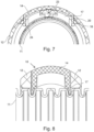
- the locking element 14 may be connected to the half-shells 12, by connecting first the secondary latching element 20 with the corresponding latching element 24 (see Fig. 6 ).
- the two half-shells 12 and the locking element 14 may be connected with each other, but not locked or fixated in an axial direction of the cylindrical body. Therefore, the protection device 10 may still be moved in said direction to be positioned in its designated position on the cylindrical body.
- the locking element 14 may be connected by the first latching element 16 and the corresponding latching element 24 (see Fig. 7 ).
- Fig. 8 shows a cross view of the protection device 10 in an assembled state. It shows that the ribs 17 are positioned in a groove of the corrugated surface of the cylindrical body 11.
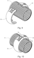
- Fig. 9 to Fig. 13 show how a protection device 10 may be assembled and placed on a cylindrical body 11.
- the provided half-shells 12 are centered and joined together by means of the connection elements 15.
- the locking element 14 may be inserted into the cut-outs 13.
- the locking element 14 may be connected by means of the secondary latching element 20 such that the protection device 10 may still be moved in an axial direction of the cylindrical body 11.
- the protection device 10 may be pre-assembled (see Fig. 11 ).
- the locking element 14 is connected to the half-shells 12 by means of the secondary latching element 20.
- the protection device 10 can be slid on the cylindrical body 11 (see Fig. 12 ).
- the protection device 10 may be moved to its designated position.
- the designated position may be a position where damage of the cylindrical body is highly likely, for example, by abrasion.
- the locking element 14 may be moved into its locking position.
- the locking element 14 may be moved into its locking position by pushing so that the first latching element 16 interacts with the corresponding latching element 24 and the ribs 17 form a form fitting with the corrugated surface of the cylindrical body 11 (see Fig. 13 ).
- a slit 19 can be seen on the outer surface of the protection device 10 in the region of the gap 18 (see Fig. 6 ) of the locking element 14.
- the slit 19 is designed for disassembling the protection device 10, for example with a screwdriver or a hook.
- the invention and design of the protection device 10 or protection sleeve allows quick and easy fixation and repositioning of said protection device without using any additional metallic or metal-like materials.
- the protection device 10 may be adapted for different cylindrical bodies 11, in particular by switching out the locking element 14.
- the locking element 14 may comprise a different inner geometry or surface, depending on the intended use.
Landscapes
- Engineering & Computer Science (AREA)
- General Engineering & Computer Science (AREA)
- Mechanical Engineering (AREA)
- Protection Of Pipes Against Damage, Friction, And Corrosion (AREA)
- Vibration Dampers (AREA)
- Details Of Indoor Wiring (AREA)
- Installation Of Indoor Wiring (AREA)
Priority Applications (2)
| Application Number | Priority Date | Filing Date | Title |
|---|---|---|---|
| EP22196172.5A EP4339499A1 (fr) | 2022-09-16 | 2022-09-16 | Dispositif de protection et procédé |
| JP2023149707A JP2024043517A (ja) | 2022-09-16 | 2023-09-15 | 保護デバイス、半シェル及び/又はロック要素の使用、並びに方法 |
Applications Claiming Priority (1)
| Application Number | Priority Date | Filing Date | Title |
|---|---|---|---|
| EP22196172.5A EP4339499A1 (fr) | 2022-09-16 | 2022-09-16 | Dispositif de protection et procédé |
Publications (1)
| Publication Number | Publication Date |
|---|---|
| EP4339499A1 true EP4339499A1 (fr) | 2024-03-20 |
Family
ID=83361338
Family Applications (1)
| Application Number | Title | Priority Date | Filing Date |
|---|---|---|---|
| EP22196172.5A Pending EP4339499A1 (fr) | 2022-09-16 | 2022-09-16 | Dispositif de protection et procédé |
Country Status (2)
| Country | Link |
|---|---|
| EP (1) | EP4339499A1 (fr) |
| JP (1) | JP2024043517A (fr) |
Citations (5)
| Publication number | Priority date | Publication date | Assignee | Title |
|---|---|---|---|---|
| DE3201948A1 (de) * | 1981-01-30 | 1982-10-28 | Hugues Jacques Saint-Mande Flimon | Schutzvorrichtung fuer futterrohre |
| DE9201386U1 (fr) * | 1992-02-05 | 1993-06-03 | Licentia Patent-Verwaltungs-Gmbh, 6000 Frankfurt, De | |
| US6761189B2 (en) * | 2001-01-19 | 2004-07-13 | Kuka Roboter Gmbh | Wearing ring |
| DE202007012036U1 (de) * | 2007-08-30 | 2009-01-08 | Reiku Gmbh | Verschleißring (Protektor) |
| DE102020007493A1 (de) * | 2020-12-08 | 2022-06-09 | Kuka Deutschland Gmbh | Leitungsprotektorring |
-
2022
- 2022-09-16 EP EP22196172.5A patent/EP4339499A1/fr active Pending
-
2023
- 2023-09-15 JP JP2023149707A patent/JP2024043517A/ja active Pending
Patent Citations (5)
| Publication number | Priority date | Publication date | Assignee | Title |
|---|---|---|---|---|
| DE3201948A1 (de) * | 1981-01-30 | 1982-10-28 | Hugues Jacques Saint-Mande Flimon | Schutzvorrichtung fuer futterrohre |
| DE9201386U1 (fr) * | 1992-02-05 | 1993-06-03 | Licentia Patent-Verwaltungs-Gmbh, 6000 Frankfurt, De | |
| US6761189B2 (en) * | 2001-01-19 | 2004-07-13 | Kuka Roboter Gmbh | Wearing ring |
| DE202007012036U1 (de) * | 2007-08-30 | 2009-01-08 | Reiku Gmbh | Verschleißring (Protektor) |
| DE102020007493A1 (de) * | 2020-12-08 | 2022-06-09 | Kuka Deutschland Gmbh | Leitungsprotektorring |
Also Published As
| Publication number | Publication date |
|---|---|
| JP2024043517A (ja) | 2024-03-29 |
Similar Documents
| Publication | Publication Date | Title |
|---|---|---|
| EP2833044B1 (fr) | Guide de tuyau hydraulique | |
| JP4932844B2 (ja) | 角度をなすように配向された空洞を有する管継手セグメント | |
| JP2000509465A (ja) | 複合ガスケット及びかかるガスケットを含むアセンブリ | |
| JP2007298176A (ja) | 管状の物体又はホース形状の物体を固定するクランプ | |
| CZ107898A3 (cs) | Zajištěný spoj mezi částmi kanalizačního potrubí a kovový proříznutý kroužek, použitelný v takovém spoji | |
| SK278545B6 (en) | The connecting element for quick connection of the flexible tubing and pipe | |
| EP4339499A1 (fr) | Dispositif de protection et procédé | |
| US6086114A (en) | Double-containment pipe assembly with conical-shaped internal anchor | |
| EP2180220B1 (fr) | Procédé de liaison de segments de tuyau | |
| KR101708477B1 (ko) | 철근연결구 | |
| TWI437179B (zh) | 用於爪形軸環之總成,相對應的爪形軸環及管形接頭 | |
| US20030025329A1 (en) | Spacer-less type pipe joint and packing ring used for the same | |
| KR101208486B1 (ko) | 철근 연결용 보조 커플러 | |
| KR200190337Y1 (ko) | 배관용신축이음장치 | |
| KR101674949B1 (ko) | 라이닝배관어댑터장치 | |
| JP2009144465A (ja) | コンクリート貫通孔用スリーブ | |
| JP7413006B2 (ja) | 合成樹脂フランジ管継手 | |
| FI104512B (fi) | Putkiliitos | |
| FI92098C (fi) | Eristysputkikanavajärjestelmä | |
| EP3736477B1 (fr) | Raccords de tuyauterie et leurs utilisations | |
| KR101985494B1 (ko) | 심플 조인트 | |
| JP2019202431A (ja) | ライニング体の連結方法、ライニング体の連結構造 | |
| FI110814B (fi) | Eristysmoduli | |
| JP3479136B2 (ja) | 管継手 | |
| KR200344488Y1 (ko) | 벨로우즈형 신축동관 연결구조 |
Legal Events
| Date | Code | Title | Description |
|---|---|---|---|
| PUAI | Public reference made under article 153(3) epc to a published international application that has entered the european phase |
Free format text: ORIGINAL CODE: 0009012 |
|
| STAA | Information on the status of an ep patent application or granted ep patent |
Free format text: STATUS: THE APPLICATION HAS BEEN PUBLISHED |
|
| AK | Designated contracting states |
Kind code of ref document: A1 Designated state(s): AL AT BE BG CH CY CZ DE DK EE ES FI FR GB GR HR HU IE IS IT LI LT LU LV MC MK MT NL NO PL PT RO RS SE SI SK SM TR |