EP4339359B1 - Installation pour la fabrication d'une bande fibreuse - Google Patents
Installation pour la fabrication d'une bande fibreuse Download PDFInfo
- Publication number
- EP4339359B1 EP4339359B1 EP23191439.1A EP23191439A EP4339359B1 EP 4339359 B1 EP4339359 B1 EP 4339359B1 EP 23191439 A EP23191439 A EP 23191439A EP 4339359 B1 EP4339359 B1 EP 4339359B1
- Authority
- EP
- European Patent Office
- Prior art keywords
- installation
- fibrous web
- binder
- wire
- section
- Prior art date
- Legal status (The legal status is an assumption and is not a legal conclusion. Google has not performed a legal analysis and makes no representation as to the accuracy of the status listed.)
- Active
Links
Images


Classifications
-
- D—TEXTILES; PAPER
- D21—PAPER-MAKING; PRODUCTION OF CELLULOSE
- D21F—PAPER-MAKING MACHINES; METHODS OF PRODUCING PAPER THEREON
- D21F9/00—Complete machines for making continuous webs of paper
- D21F9/02—Complete machines for making continuous webs of paper of the Fourdrinier type
-
- D—TEXTILES; PAPER
- D21—PAPER-MAKING; PRODUCTION OF CELLULOSE
- D21F—PAPER-MAKING MACHINES; METHODS OF PRODUCING PAPER THEREON
- D21F5/00—Dryer section of machines for making continuous webs of paper
- D21F5/02—Drying on cylinders
-
- D—TEXTILES; PAPER
- D21—PAPER-MAKING; PRODUCTION OF CELLULOSE
- D21F—PAPER-MAKING MACHINES; METHODS OF PRODUCING PAPER THEREON
- D21F11/00—Processes for making continuous lengths of paper, or of cardboard, or of wet web for fibre board production, on paper-making machines
- D21F11/02—Processes for making continuous lengths of paper, or of cardboard, or of wet web for fibre board production, on paper-making machines of the Fourdrinier type
-
- D—TEXTILES; PAPER
- D21—PAPER-MAKING; PRODUCTION OF CELLULOSE
- D21F—PAPER-MAKING MACHINES; METHODS OF PRODUCING PAPER THEREON
- D21F9/00—Complete machines for making continuous webs of paper
Definitions
- the invention relates to a plant for producing a fibrous web, in particular a long-fiber paper or wet-laid nonwoven web, comprising a binder screen section having a binder screen for applying an aqueous binder to the fibrous web and a drying section having a drying screen for drying and consolidating the fibrous web, wherein the binder screen section and the drying section are arranged at a distance from one another so that the fibrous web is guided from the binder screen to the drying screen in a free draw.
- a fiber suspension unit for example a glass fiber slurry
- a glass fiber slurry is produced by adding a glass fiber having a fiber length in the range of 6 to 40 mm, preferably 8 to 30 mm, in particular 10 to 25 mm, to typical white water in a pulper to disperse the glass fiber in the white water to form the glass fiber slurry with a fiber concentration of approximately 0.2 to 1.0 percent by weight and is then added to a white water stream.
- This glass fiber slurry is then applied to an inclined screen, which runs at least partially at an angle to the horizontal, in a web former with at least one at least single-layer, preferably multi-layer headbox, and dewatered.
- the dewatering of the glass fiber slurry forms a glass fiber wet web.
- the formed glass fiber wet web is then transferred to a binder screen, which runs at least partially horizontally or approximately horizontally, in a binder screen section.
- a binder screen which runs at least partially horizontally or approximately horizontally, in a binder screen section.
- at least one aqueous binder such as an aqueous urea-formaldehyde (UF) resin-based binder
- UF urea-formaldehyde
- the aqueous binder solution is preferably applied to the wet glass fiber nonwoven fabric using a curtain coater or a swap and squeeze applicator, although other application methods are also possible, such as Suitable for spraying.
- the wet and still unbonded glass fiber nonwoven is then transferred to a drying section with a drying screen for drying and curing (polymerization) of the binder that bonds the glass fibers together in the glass fiber nonwoven.
- the drying section can, for example, have a heated continuous oven or a drum or belt dryer, whereby the glass fiber nonwoven is generally exposed to a temperature of 100 to 250 °C, but for no longer than 1 to 2 minutes.
- the glass fiber nonwoven which has a basis weight range of 40 to 200 g/m2 and a binder content of 10 to 30%, is wound onto winding cores in a winder to form winding rolls, so that it can then be fed to subsequent processing or finishing stations.
- the invention is based on the object of avoiding or at least reducing the aforementioned problems.
- the transfer of the wet and still unbonded fibrous web from the binder wire section to the dryer section in an open draw is to be made more reliable, so that it does not negatively impact the runnability of the system and functions without wrinkling and/or web breaks even at high machine speeds and/or low specific web weights.
- the object is achieved by the features of the independent claims.
- the dependent claims relate to advantageous developments of the invention.
- the object is achieved according to the invention in a system of the type mentioned above by arranging at least one air extraction device at the edge of the system in the region of the distance between the binder wire section and the dryer section.
- the inventors have recognized that the primary cause of wrinkling in the fibrous web is the air currents generated by the binder fabric and the counter-rotating dryer fabric in the threading area between the binder fabric and the dryer section, particularly at high operating speeds and/or low basis weights of the web. These air currents generate turbulence, particularly in the edge area of the system. This stretches the fibrous web, leading to wrinkling or even web tearing in the system. This is described in more detail below. Figure 2 illustrated schematically.
- baffles are used to guide the flow.
- This problem could only be solved through the inventive use of at least one air extraction device.
- This at least one air extraction device enables a stable flow to be created in the transfer area between the binder wire and dryer sections, which is not influenced by the aforementioned disruptive factors.
- the at least one air extraction device is arranged, viewed vertically, substantially below the fibrous web guided in free tension, but does not extend from the edge of the system to below the fibrous web guided in free tension.
- Viewed vertically, substantially below means that the at least one air extraction device is arranged, in the vertical direction, i.e., in the direction of gravity, predominantly, preferably completely, below the fibrous web when, during normal operation of the system, it is conveyed from the binder wire section to the dryer section.
- the at least one edge-side air extraction device should not extend horizontally from the edge to below the fibrous web being transferred in free tension, in order to avoid the aforementioned problem of high cleaning and maintenance costs.
- air extraction device preferably refers to a suction box. Such a suction box typically has an opening through which the air is extracted.
- the air extraction device can be connected to a negative pressure source, such as a vacuum pump, via piping or the like.
- the invention has proven particularly efficient when an air extraction device is arranged on both the drive side and the driver side of the system.
- the drive-side and driver-side air extraction devices are designed such that the negative pressure they generate can be adjusted independently of one another.
- the same negative pressure does not always have to be present at both air extraction devices, nor does it require the same amount of air to be extracted per unit of time.
- the adjustment can be made via a control or a controller. Normally, however, it is sufficient to adjust the negative pressure only once.
- the installation space below the freely guided fibrous web is kept clear, at least in the area between a last roller of the binder wire section, over which the binder wire is guided when it releases the fibrous web, and a first roller of the dryer section, over which the dryer wire is guided when it receives the fibrous web.
- Air can then be extracted particularly efficiently from this cleared installation space by the at least one, preferably two, air extraction device(s).
- the binder screen runs horizontally or approximately horizontally at least in some sections and/or that the binder screen section has at least one binder headbox.
- the plant may also further comprise a fiber suspension unit for producing the aqueous suspension for the forming section.
- the system may also comprise a winder for continuously winding the fibrous web onto winding cores to form winding rolls, wherein the winder is located downstream of the drying section in the process direction of the fibrous web through the system.
- At least one, preferably adjustable, blowing device for contactless, suspended guidance of the fibrous web by means of air or another flowable medium is provided between the binder wire section and the dryer section.
- This device has several independently controllable blowing zones transverse to the running direction of the fibrous web.
- the mode of operation of such a blowing device, which blows from above onto the fibrous web in the transfer area to promote contactless, suspended guidance of the fibrous web is described in detail in the publication mentioned above.
- WO 2009/144195 A1 described, to whose content in this regard and with regard to further advantageous embodiments of the blowing device, reference is hereby explicitly made.
- a further aspect of the present invention relates to the use of a previously described plant according to the invention for producing a fibrous web, in particular a long-fiber paper or wet-laid nonwoven web, wherein, during normal operation of the plant, air is extracted from the area between the binder wire section and the dryer section by means of the at least one edge-side air extraction device.
- the present invention has proven particularly effective when the fibrous web is a wet-laid glass fiber mat.
- the transfer of the not yet dry and therefore sticky glass fiber mat from the binder wire to the dryer section is particularly susceptible to the contamination problem described above.
- the advantages of the present invention are particularly effective when the fibrous web is produced at a speed of at least 170 m/min and/or when the fibrous web has a basis weight of less than 30 g/m 2 , since the risk of wrinkling of the fibrous web in the transfer area between the binder wire and the dryer section is particularly high.
- the Figure 1 shows a schematic layout of a plant 1 for producing a fibrous web 2, in particular a long-fiber paper or wet-laid nonwoven web.
- This plant 1 for producing the fibrous web 2 comprises a fibrous material suspension unit 3, a forming section 4, which has an inclined wire 5 running at least in sections at an angle ⁇ to the horizontal H and at least one at least single-layer, preferably multi-layer headbox 6, a Binder screen section 7, which has a binder screen 8 running at least partially horizontally or approximately horizontally and at least one binder headbox 9, a dryer section 10 having a dryer screen 11 and a winder 12 for continuously winding the fibrous web 2 onto winding cores 13 to form winding rolls 14.
- the aqueous suspension can, for example, be a glass fiber slurry comprising glass fibers with a fiber length in the range of 6 to 40 mm, preferably 8 to 30 mm, in particular 10 to 25 mm, and so-called white water, and having a fiber concentration of approximately 0.2 to 1.0 percent by weight.
- the fiber suspension unit 3 is followed by the next process step, namely the dewatering of the aqueous suspension and the formation of the fibrous web 2 with the aid of the inclined screen 5 arranged in the forming section 4.
- the aqueous suspension is applied to the inclined screen 5 by means of an at least single-layer, preferably multi-layer, headbox 6.
- the water filtered from the aqueous suspension below the inclined screen 5 is recirculated according to arrow 21 and, for example, added to the aqueous suspension leaving the second container ("pulper") 17 of the fiber suspension unit 3.
- At least one aqueous binder such as an aqueous urea-formaldehyde (UF) resin-based binder
- a binder head 9 to the still wet fibrous web 2 lying on the binder wire 8 of the binder wire section 7.
- the excess binder is then also sucked off in a known manner.
- the aqueous binder can also be applied in a manner not shown using a curtain coater or an exchange and squeeze applicator the still wet fiber web 2, but other application methods, such as spraying, are also suitable.
- the next process step dries and consolidates the still-wet fibrous web 2 by curing (polymerizing) the binder, which bonds the glass fibers together in the glass fiber mat.
- it is passed through the drying section 10, which has the dryer wire 11 and comprises two heated continuous ovens 22 (shown) or a drum or belt dryer (not shown).
- the fibrous web 2 is typically exposed to a temperature of 100°C to 250°C, but for no longer than 1 to 2 minutes.
- the fibrous web which has a basis weight range of 40 to 200 g/m 2 and a binder content of 10 to 30%, is wound in the winder 12 onto winding cores 14 to form winding rolls 13 in order to then be fed to subsequent processing or finishing stations.
- an adjustable blowing device for contactless floating guidance of the fibrous web 2 by means of air or another flowable medium can be provided between the binder wire section 7 and the dryer section 10, which has a plurality of independently controllable/regulatable blowing zones transversely to the running direction of the fibrous web 2.
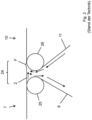
- Fig. 2 shows a schematic side view of the transfer area 24 between the binder wire section 7 and the dryer section 10, as well as the problem of the formation of wrinkles F in the prior art.
- the fibrous web 2 is transported on the binder wire 8 to a last roller 25 of the binder wire section 7, then guided in a free draw to a first roller 26 of the subsequent dryer section 10, where it is picked up by the dryer wire 11 and transported further.
- the arrows with the filled tips illustrate the air flows that are dragged along by the binder wire 8 of the fibrous web 2 and the dryer wire 11 on their surfaces. These air flows cause turbulence in the space between the two rollers 25 and 26, which has a negative effect on the fibrous web 2 guided in the free draw.
- wrinkles are critical for the further processing of the fibrous web 2 and can even lead to the tearing of the fibrous web 2.
- Fig. 3 shows essentially the same schematic side view of the transfer area 24 as Fig. 2 , but with the solution according to the invention, which prevents the formation of wrinkles in the fibrous web 2.
- An essential component of this solution is an air extraction device 27, which is arranged in the transfer area 24 vertically below, but at the edge of, the fibrous web 2 guided in free tension.
- the air extraction device 27 is not located directly below the fibrous web 2, but is arranged in the cross-machine direction (direction orthogonal to the image plane of the Fig. 2 ) is arranged laterally offset to the latter.
- the air extraction device 27 has an opening area 28 (cf. Fig.
- the system 2 comprises on both its driver and drive sides such an air extraction device 24 as in Fig. 4 shown schematically.
- an air extraction device 24 as in Fig. 4 shown schematically.
- the system 2 comprises on both its driver and drive sides such an air extraction device 24 as in Fig. 4 shown schematically.
- FIG. 4 In the three-dimensional representation of the Fig. 4
- only the first roller 26 of the dryer section 10, a part of the dryer fabric 11, which moves in the direction of the arrow, and the two edge-side air extraction devices 27 are shown.
- the above-mentioned opening area 28 can be seen on one of these two air extraction devices 27.
- the two air extraction devices 27 are designed here as suction boxes.
Landscapes
- Paper (AREA)
Claims (15)
- Installation (1) pour la fabrication d'une bande de matière fibreuse (2), notamment d'une bande de papier à fibres longues ou d'une bande de non-tissé humide, comprenant une section de tamisage de liant (7) présentant un tamis de liant (8) pour l'application d'un liant aqueux sur la bande de matière fibreuse (2) et une section de séchage (10) présentant un tamis de séchage (11) pour le séchage et la consolidation de la bande de matière fibreuse (2), la section de tamisage de liant (7) et la section de séchage (11) étant agencées à une distance l'une de l'autre de telle sorte que la bande de matière fibreuse (1) est guidée du tamis de liant (8) au tamis de séchage (11) dans une traction libre,
caractérisée en ce qu'au moins un dispositif d'aspiration d'air (27) est agencé sur le bord de l'installation (1) dans la zone de la distance entre la section de tamisage de liant (7) et la section de séchage (11). - Installation (1) selon la revendication 1,
caractérisée en ce que l'au moins un dispositif d'aspiration d'air (27) est agencé, considéré dans la direction de la hauteur, essentiellement en dessous de la bande de matière fibreuse (2) guidée en traction libre, mais ne s'étend pas depuis le bord de l'installation (1) jusque sous la bande de matière fibreuse (2) guidée en traction libre. - Installation (1) selon la revendication 1 ou 2,
caractérisée en ce que l'au moins un dispositif d'aspiration d'air (27) est un caisson d'aspiration. - Installation (1) selon l'une quelconque des revendications précédentes,
caractérisée en ce qu'un dispositif d'aspiration d'air (27) est agencé à la fois sur le côté d'entraînement et sur le côté de guidage de l'installation. - Installation (1) selon la revendication 4,
caractérisée en ce que les dispositifs d'aspiration d'air côté d'entraînement et côté de guidage (27) sont réalisés de telle sorte que la dépression qu'ils produisent peut être réglée indépendamment l'une de l'autre. - Installation (1) selon l'une quelconque des revendications précédentes,
caractérisée en ce que l'espace de construction sous la bande de matière fibreuse (2) guidée en traction libre est maintenu libre au moins dans la zone entre un dernier rouleau (25) de la section de tamisage de liant (7), sur lequel le tamis de liant (8) est guidé lorsque celui-ci délivre la bande de matière fibreuse (2), et un premier rouleau (26) de la section de séchage (10), sur lequel le tamis de séchage (11) est guidé lorsque celui-ci reçoit la bande de matière fibreuse (2). - Installation (1) selon l'une quelconque des revendications précédentes,
caractérisée en ce que le tamis de liant (8) s'étend au moins par endroits horizontalement ou approximativement horizontalement et/ou la section de tamisage de liant (7) présente au moins une arrivée de matière de liant (9). - Installation (1) selon l'une quelconque des revendications précédentes,
caractérisée en ce que l'installation (1) comprend en outre une section de formage (4) pour la déshydratation d'une suspension aqueuse, qui est placée en amont de la section de tamisage de liant (7) dans la direction de traitement de la bande de matière fibreuse (2) par l'installation (1), la section de formage (4) comprenant de préférence un formateur à tamis incliné, qui présente un tamis incliné (5) s'étendant au moins par endroits selon un angle (α) par rapport à l'horizontale (H) et au moins une caisse de tête (6) au moins à une couche, de préférence à plusieurs couches. - Installation (1) selon la revendication 8,
caractérisée en ce que l'installation (1) comprend en outre une unité de mise en suspension de fibres (3) pour la production de la suspension aqueuse pour la section de formage (4). - Installation (1) selon l'une quelconque des revendications précédentes,
caractérisée en ce que l'installation (1) comprend en outre un enrouleur (12) pour enrouler en continu la bande de matière fibreuse (2) sur des noyaux d'enroulement (13) en des rouleaux d'enroulement (14), l'enrouleur (12) étant placé en aval de la section de séchage (10) dans la direction de traitement de la bande de matière fibreuse (2) par l'installation (1). - Installation (1) selon l'une quelconque des revendications précédentes,
caractérisée en ce qu'il est prévu entre la section de tamisage de liant (7) et la section de séchage (11) au moins un dispositif de soufflage, de préférence réglable, pour le guidage en suspension sans contact de la bande de matière fibreuse (2) au moyen d'air ou d'un autre fluide apte à s'écouler, qui présente transversalement à la direction de déplacement de la bande de matière fibreuse (2) plusieurs zones de soufflage pouvant être commandées/réglées indépendamment les unes des autres. - Utilisation d'une installation (1) selon l'une quelconque des revendications précédentes pour la fabrication d'une bande de matière fibreuse (2), notamment d'une bande de papier à fibres longues ou d'une bande de non-tissé humide, dans laquelle, lors du fonctionnement conforme de l'installation (1), de l'air est aspiré hors de la zone située entre la section de tamisage de liant (7) et la section de séchage (11) au moyen de l'au moins un dispositif d'aspiration d'air (27) situé sur le bord.
- Utilisation selon la revendication 12,
caractérisée en ce que la bande de matière fibreuse (2) est une bande de non-tissé de verre déposée par voie humide. - Utilisation selon la revendication 12 ou 13,
caractérisée en ce que la bande de matière fibreuse (2) est produite à une vitesse d'au moins 170 m/min. - Utilisation selon l'une quelconque des revendications 12 à 14,
caractérisée en ce que la bande de matière fibreuse (2) présente un poids par unité de surface inférieur à 30 g/m2.
Applications Claiming Priority (1)
| Application Number | Priority Date | Filing Date | Title |
|---|---|---|---|
| DE102022123265.4A DE102022123265A1 (de) | 2022-09-13 | 2022-09-13 | Anlage zur Herstellung einer Faserstoffbahn |
Publications (2)
| Publication Number | Publication Date |
|---|---|
| EP4339359A1 EP4339359A1 (fr) | 2024-03-20 |
| EP4339359B1 true EP4339359B1 (fr) | 2025-05-07 |
Family
ID=89898828
Family Applications (1)
| Application Number | Title | Priority Date | Filing Date |
|---|---|---|---|
| EP23191439.1A Active EP4339359B1 (fr) | 2022-09-13 | 2023-08-15 | Installation pour la fabrication d'une bande fibreuse |
Country Status (3)
| Country | Link |
|---|---|
| US (1) | US12546060B2 (fr) |
| EP (1) | EP4339359B1 (fr) |
| DE (1) | DE102022123265A1 (fr) |
Family Cites Families (4)
| Publication number | Priority date | Publication date | Assignee | Title |
|---|---|---|---|---|
| DE19601989C2 (de) * | 1996-01-20 | 2002-01-31 | Voith Paper Patent Gmbh | Anordnung zum Führen einer Materialbahn |
| US20070039703A1 (en) * | 2005-08-19 | 2007-02-22 | Lee Jerry H | Wet formed mat having improved hot wet tensile strengths |
| DE102008002087A1 (de) | 2008-05-29 | 2009-12-03 | Voith Patent Gmbh | Anlage zur Herstellung einer Faserstoffbahn |
| JP7151220B2 (ja) * | 2018-07-06 | 2022-10-12 | セイコーエプソン株式会社 | 測定装置、ウェブ加工装置、及び、繊維原料再生装置 |
-
2022
- 2022-09-13 DE DE102022123265.4A patent/DE102022123265A1/de not_active Withdrawn
-
2023
- 2023-08-15 EP EP23191439.1A patent/EP4339359B1/fr active Active
- 2023-09-13 US US18/466,149 patent/US12546060B2/en active Active
Also Published As
| Publication number | Publication date |
|---|---|
| EP4339359A1 (fr) | 2024-03-20 |
| US12546060B2 (en) | 2026-02-10 |
| DE102022123265A1 (de) | 2024-03-14 |
| US20240084508A1 (en) | 2024-03-14 |
Similar Documents
| Publication | Publication Date | Title |
|---|---|---|
| DE69620020T2 (de) | Verfahren und vorrichtung in einer papiermaschine | |
| DE60020238T2 (de) | Verfahren und vorrichtung in der trockenpartieeiner papiermaschine oder dergleichen | |
| DE69527097T2 (de) | Verfahren zur Herstellung von Papier mit veredelten Oberflächen und Trockenpartie einer Papiermaschine | |
| AT509802B1 (de) | Verfahren und anlage zur behandlung einer faserbahn | |
| EP3250750B1 (fr) | Procédé et dispositif servant à produire des non-tissés par voie humide | |
| DE2753201A1 (de) | Verfahren fuer die behandlung einer papierbahn in der nasspartie einer papiermaschine | |
| EP2240640B1 (fr) | Train de séchage | |
| DE69119859T2 (de) | Verfahren und Vorrichtung in der Trockenpartie einer Papiermaschine zum Einfädeln einer Papierbahn | |
| EP2288749B1 (fr) | Installation destinée à fabriquer une bande de matière fibreuse | |
| EP4339359B1 (fr) | Installation pour la fabrication d'une bande fibreuse | |
| WO2009065433A1 (fr) | Procédé et dispositif pour transférer une bande de papier d'un tissu de soutien sur un autre | |
| EP3535445A1 (fr) | Procédé de fabrication d'un non-tissé obtenu par voie humide | |
| WO2003071028A1 (fr) | Dispositif de lissage | |
| DE102021121847B4 (de) | Maschine zur Herstellung und/oder Behandlung einer Faserstoffbahn | |
| EP3088603B1 (fr) | Procede et dispositif de production de non-tisses par voie humide | |
| DE102009027608A1 (de) | Trockenpartie | |
| EP4328376B1 (fr) | Formeur à tamis oblique | |
| DE102004003899A1 (de) | Vorrichtung zum Führen einer laufenden Faserstoffbahn | |
| DE102021113491A1 (de) | Formierpartie einer Faserbahn-Herstellungslinie | |
| DE202013105964U1 (de) | Trockenpartie einer Faserbahnmaschine | |
| EP2659062A1 (fr) | Section de séchage d'une machine pour la production d'une bande continue de matière fibreuse | |
| DE102023101609A1 (de) | Maschine und Verfahren zur Herstellung oder Behandlung einer Faserstoffbahn | |
| EP1460171B1 (fr) | Procédé de traitement d'une bande fibreuse | |
| AT506989B1 (de) | Verfahren und anlage zur durchführung einer seillosen bahneinführung | |
| EP2655735A1 (fr) | Dispositif pour fabriquer et/ou traiter des feuilles continues de matériau |
Legal Events
| Date | Code | Title | Description |
|---|---|---|---|
| PUAI | Public reference made under article 153(3) epc to a published international application that has entered the european phase |
Free format text: ORIGINAL CODE: 0009012 |
|
| STAA | Information on the status of an ep patent application or granted ep patent |
Free format text: STATUS: THE APPLICATION HAS BEEN PUBLISHED |
|
| AK | Designated contracting states |
Kind code of ref document: A1 Designated state(s): AL AT BE BG CH CY CZ DE DK EE ES FI FR GB GR HR HU IE IS IT LI LT LU LV MC ME MK MT NL NO PL PT RO RS SE SI SK SM TR |
|
| STAA | Information on the status of an ep patent application or granted ep patent |
Free format text: STATUS: REQUEST FOR EXAMINATION WAS MADE |
|
| 17P | Request for examination filed |
Effective date: 20240920 |
|
| RBV | Designated contracting states (corrected) |
Designated state(s): AL AT BE BG CH CY CZ DE DK EE ES FI FR GB GR HR HU IE IS IT LI LT LU LV MC ME MK MT NL NO PL PT RO RS SE SI SK SM TR |
|
| GRAP | Despatch of communication of intention to grant a patent |
Free format text: ORIGINAL CODE: EPIDOSNIGR1 |
|
| STAA | Information on the status of an ep patent application or granted ep patent |
Free format text: STATUS: GRANT OF PATENT IS INTENDED |
|
| INTG | Intention to grant announced |
Effective date: 20250220 |
|
| GRAS | Grant fee paid |
Free format text: ORIGINAL CODE: EPIDOSNIGR3 |
|
| GRAA | (expected) grant |
Free format text: ORIGINAL CODE: 0009210 |
|
| STAA | Information on the status of an ep patent application or granted ep patent |
Free format text: STATUS: THE PATENT HAS BEEN GRANTED |
|
| AK | Designated contracting states |
Kind code of ref document: B1 Designated state(s): AL AT BE BG CH CY CZ DE DK EE ES FI FR GB GR HR HU IE IS IT LI LT LU LV MC ME MK MT NL NO PL PT RO RS SE SI SK SM TR |
|
| REG | Reference to a national code |
Ref country code: GB Ref legal event code: FG4D Free format text: NOT ENGLISH |
|
| REG | Reference to a national code |
Ref country code: CH Ref legal event code: EP |
|
| REG | Reference to a national code |
Ref country code: DE Ref legal event code: R096 Ref document number: 502023000949 Country of ref document: DE |
|
| REG | Reference to a national code |
Ref country code: IE Ref legal event code: FG4D Free format text: LANGUAGE OF EP DOCUMENT: GERMAN |
|
| REG | Reference to a national code |
Ref country code: NL Ref legal event code: MP Effective date: 20250507 |
|
| PG25 | Lapsed in a contracting state [announced via postgrant information from national office to epo] |
Ref country code: FI Free format text: LAPSE BECAUSE OF FAILURE TO SUBMIT A TRANSLATION OF THE DESCRIPTION OR TO PAY THE FEE WITHIN THE PRESCRIBED TIME-LIMIT Effective date: 20250507 Ref country code: PT Free format text: LAPSE BECAUSE OF FAILURE TO SUBMIT A TRANSLATION OF THE DESCRIPTION OR TO PAY THE FEE WITHIN THE PRESCRIBED TIME-LIMIT Effective date: 20250908 Ref country code: ES Free format text: LAPSE BECAUSE OF FAILURE TO SUBMIT A TRANSLATION OF THE DESCRIPTION OR TO PAY THE FEE WITHIN THE PRESCRIBED TIME-LIMIT Effective date: 20250507 |
|
| PGFP | Annual fee paid to national office [announced via postgrant information from national office to epo] |
Ref country code: DE Payment date: 20250820 Year of fee payment: 3 |
|
| REG | Reference to a national code |
Ref country code: LT Ref legal event code: MG9D |
|
| PG25 | Lapsed in a contracting state [announced via postgrant information from national office to epo] |
Ref country code: GR Free format text: LAPSE BECAUSE OF FAILURE TO SUBMIT A TRANSLATION OF THE DESCRIPTION OR TO PAY THE FEE WITHIN THE PRESCRIBED TIME-LIMIT Effective date: 20250808 Ref country code: NO Free format text: LAPSE BECAUSE OF FAILURE TO SUBMIT A TRANSLATION OF THE DESCRIPTION OR TO PAY THE FEE WITHIN THE PRESCRIBED TIME-LIMIT Effective date: 20250807 |
|
| PG25 | Lapsed in a contracting state [announced via postgrant information from national office to epo] |
Ref country code: NL Free format text: LAPSE BECAUSE OF FAILURE TO SUBMIT A TRANSLATION OF THE DESCRIPTION OR TO PAY THE FEE WITHIN THE PRESCRIBED TIME-LIMIT Effective date: 20250507 Ref country code: PL Free format text: LAPSE BECAUSE OF FAILURE TO SUBMIT A TRANSLATION OF THE DESCRIPTION OR TO PAY THE FEE WITHIN THE PRESCRIBED TIME-LIMIT Effective date: 20250507 |
|
| PG25 | Lapsed in a contracting state [announced via postgrant information from national office to epo] |
Ref country code: BG Free format text: LAPSE BECAUSE OF FAILURE TO SUBMIT A TRANSLATION OF THE DESCRIPTION OR TO PAY THE FEE WITHIN THE PRESCRIBED TIME-LIMIT Effective date: 20250507 |
|
| PG25 | Lapsed in a contracting state [announced via postgrant information from national office to epo] |
Ref country code: HR Free format text: LAPSE BECAUSE OF FAILURE TO SUBMIT A TRANSLATION OF THE DESCRIPTION OR TO PAY THE FEE WITHIN THE PRESCRIBED TIME-LIMIT Effective date: 20250507 |
|
| PGFP | Annual fee paid to national office [announced via postgrant information from national office to epo] |
Ref country code: AT Payment date: 20251020 Year of fee payment: 3 Ref country code: FR Payment date: 20250828 Year of fee payment: 3 |
|
| PG25 | Lapsed in a contracting state [announced via postgrant information from national office to epo] |
Ref country code: RS Free format text: LAPSE BECAUSE OF FAILURE TO SUBMIT A TRANSLATION OF THE DESCRIPTION OR TO PAY THE FEE WITHIN THE PRESCRIBED TIME-LIMIT Effective date: 20250807 |
|
| PG25 | Lapsed in a contracting state [announced via postgrant information from national office to epo] |
Ref country code: IS Free format text: LAPSE BECAUSE OF FAILURE TO SUBMIT A TRANSLATION OF THE DESCRIPTION OR TO PAY THE FEE WITHIN THE PRESCRIBED TIME-LIMIT Effective date: 20250907 |
|
| PG25 | Lapsed in a contracting state [announced via postgrant information from national office to epo] |
Ref country code: LV Free format text: LAPSE BECAUSE OF FAILURE TO SUBMIT A TRANSLATION OF THE DESCRIPTION OR TO PAY THE FEE WITHIN THE PRESCRIBED TIME-LIMIT Effective date: 20250507 |
|
| PG25 | Lapsed in a contracting state [announced via postgrant information from national office to epo] |
Ref country code: DK Free format text: LAPSE BECAUSE OF FAILURE TO SUBMIT A TRANSLATION OF THE DESCRIPTION OR TO PAY THE FEE WITHIN THE PRESCRIBED TIME-LIMIT Effective date: 20250507 Ref country code: SM Free format text: LAPSE BECAUSE OF FAILURE TO SUBMIT A TRANSLATION OF THE DESCRIPTION OR TO PAY THE FEE WITHIN THE PRESCRIBED TIME-LIMIT Effective date: 20250507 |
|
| PG25 | Lapsed in a contracting state [announced via postgrant information from national office to epo] |
Ref country code: CZ Free format text: LAPSE BECAUSE OF FAILURE TO SUBMIT A TRANSLATION OF THE DESCRIPTION OR TO PAY THE FEE WITHIN THE PRESCRIBED TIME-LIMIT Effective date: 20250507 |
|
| PG25 | Lapsed in a contracting state [announced via postgrant information from national office to epo] |
Ref country code: EE Free format text: LAPSE BECAUSE OF FAILURE TO SUBMIT A TRANSLATION OF THE DESCRIPTION OR TO PAY THE FEE WITHIN THE PRESCRIBED TIME-LIMIT Effective date: 20250507 |
|
| PG25 | Lapsed in a contracting state [announced via postgrant information from national office to epo] |
Ref country code: SK Free format text: LAPSE BECAUSE OF FAILURE TO SUBMIT A TRANSLATION OF THE DESCRIPTION OR TO PAY THE FEE WITHIN THE PRESCRIBED TIME-LIMIT Effective date: 20250507 |
|
| PG25 | Lapsed in a contracting state [announced via postgrant information from national office to epo] |
Ref country code: IT Free format text: LAPSE BECAUSE OF FAILURE TO SUBMIT A TRANSLATION OF THE DESCRIPTION OR TO PAY THE FEE WITHIN THE PRESCRIBED TIME-LIMIT Effective date: 20250507 |
|
| PG25 | Lapsed in a contracting state [announced via postgrant information from national office to epo] |
Ref country code: RO Free format text: LAPSE BECAUSE OF FAILURE TO SUBMIT A TRANSLATION OF THE DESCRIPTION OR TO PAY THE FEE WITHIN THE PRESCRIBED TIME-LIMIT Effective date: 20250507 |
|
| PLBE | No opposition filed within time limit |
Free format text: ORIGINAL CODE: 0009261 |
|
| STAA | Information on the status of an ep patent application or granted ep patent |
Free format text: STATUS: NO OPPOSITION FILED WITHIN TIME LIMIT |
|
| REG | Reference to a national code |
Ref country code: CH Ref legal event code: L10 Free format text: ST27 STATUS EVENT CODE: U-0-0-L10-L00 (AS PROVIDED BY THE NATIONAL OFFICE) Effective date: 20260318 |