EP4339067B1 - Weichen- oder kreuzungskomponente mit lösbarer verbindung sowie verfahren und anordnung zur überwachung der lösbaren verbindung - Google Patents
Weichen- oder kreuzungskomponente mit lösbarer verbindung sowie verfahren und anordnung zur überwachung der lösbaren verbindung Download PDFInfo
- Publication number
- EP4339067B1 EP4339067B1 EP22196252.5A EP22196252A EP4339067B1 EP 4339067 B1 EP4339067 B1 EP 4339067B1 EP 22196252 A EP22196252 A EP 22196252A EP 4339067 B1 EP4339067 B1 EP 4339067B1
- Authority
- EP
- European Patent Office
- Prior art keywords
- component
- sensor
- frog
- detachable connection
- switch
- Prior art date
- Legal status (The legal status is an assumption and is not a legal conclusion. Google has not performed a legal analysis and makes no representation as to the accuracy of the status listed.)
- Active
Links
Images

Classifications
-
- B—PERFORMING OPERATIONS; TRANSPORTING
- B61—RAILWAYS
- B61L—GUIDING RAILWAY TRAFFIC; ENSURING THE SAFETY OF RAILWAY TRAFFIC
- B61L23/00—Control, warning or like safety means along the route or between vehicles or trains
- B61L23/04—Control, warning or like safety means along the route or between vehicles or trains for monitoring the mechanical state of the route
- B61L23/042—Track changes detection
- B61L23/045—Rail wear
-
- B—PERFORMING OPERATIONS; TRANSPORTING
- B61—RAILWAYS
- B61L—GUIDING RAILWAY TRAFFIC; ENSURING THE SAFETY OF RAILWAY TRAFFIC
- B61L23/00—Control, warning or like safety means along the route or between vehicles or trains
- B61L23/04—Control, warning or like safety means along the route or between vehicles or trains for monitoring the mechanical state of the route
- B61L23/042—Track changes detection
- B61L23/047—Track or rail movements
-
- B—PERFORMING OPERATIONS; TRANSPORTING
- B61—RAILWAYS
- B61L—GUIDING RAILWAY TRAFFIC; ENSURING THE SAFETY OF RAILWAY TRAFFIC
- B61L27/00—Central railway traffic control systems; Trackside control; Communication systems specially adapted therefor
- B61L27/50—Trackside diagnosis or maintenance, e.g. software upgrades
- B61L27/53—Trackside diagnosis or maintenance, e.g. software upgrades for trackside elements or systems, e.g. trackside supervision of trackside control system conditions
-
- E—FIXED CONSTRUCTIONS
- E01—CONSTRUCTION OF ROADS, RAILWAYS, OR BRIDGES
- E01B—PERMANENT WAY; PERMANENT-WAY TOOLS; MACHINES FOR MAKING RAILWAYS OF ALL KINDS
- E01B7/00—Switches; Crossings
- E01B7/10—Frogs
- E01B7/12—Fixed frogs made of one part or composite
Definitions
- the present invention relates to a switch or crossing component in the form of a frog or a tongue rail device, comprising a base component in the form of a frog block or tongue rail adapter, a replaceable component in the form of a frog insert or a tongue rail, at least one detachable connection, such as a screw connection or clamping, by means of which the replaceable component can be connected to the base component, in particular in a force-fitting and/or form-fitting manner.
- the invention also relates to a method for monitoring a detachable connection of a switch or crossing component in the form of a frog or a tongue rail device, wherein by means of the detachable connection a replaceable component in the form of a frog insert or a tongue rail is fastened to a base component in the form of a frog block or a tongue rail adapter and wherein by means of a sensor a signal for checking the quality, in particular the force transmission or the form fit, of the detachable connection is detected, which signal is generated when a rail vehicle passes over the switch or crossing component and is representative of the quality of the detachable connection,
- a remote monitoring system for a railway network for monitoring operating parameters of at least one switch system of the railway network is known.
- Each switch system is designed to include a set of sensors, each adapted to measure a property value representative of a particular property.
- the sensors are each connected to a data acquisition unit that stores an algorithm for managing the acquired measurement data.
- means are provided for comparing the measured data with at least one threshold value which is representative of the limit value for a corresponding operating parameter.
- the known arrangement includes, for example, a replaceable component in the form of a check rail, which is connected to a base component in the form of a track via a detachable connection.
- a sensor is provided to monitor the clamping of the check rail to the track, which is achieved by the detachable connection.
- This sensor is located in the check rail, which means that when the check rail is replaced, the sensor must also be replaced or dismantled. This involves increased effort.
- the method also provides for monitoring the quality of the clamping of the check rail using measurement signals supplied by an acceleration sensor which detects the shocks generated by a wheel on the check rail.
- the DE 200 16 674 U1 concerns a system for measuring the approach to the frog point of a switch.
- the system is characterized by a structure-borne noise sensor that is inserted into the frog of the switch or a component connected to this frog. If the switch is approached at an acute angle and the flange of a wheel hits the frog point due to misalignment or wear on one of the check rails, a violent shock occurs, with the resulting structure-borne noise pulse being transmitted through the base plate of the frog to the wing rail firmly screwed to it and thus registered by the structure-borne noise sensor.
- the sensor is located laterally in a wing rail and would be inaccessible on tracks that are typically covered in trams.
- the DE 10 2004 014 282 B4 relates to a method for diagnosis and condition monitoring in the overrun area of a switch and/or a crossing and/or a crossing switch of a railway line.
- a measurement of the acceleration of the switch or the crossing point is carried out at the rigid frog or at the crossing point at at least one location on the frog or crossing point in at least one spatial direction, which acceleration is generated by the train passing over the switch or the crossing point.
- a detachable connection is not monitored.
- the present invention is based on the object of developing a switch or crossing component, a method, or an arrangement of the type mentioned above in such a way that the monitoring of a detachable connection, such as the fastening or clamping of replaceable components, is simplified and improved using sensors.
- a loose screw connection/clamp should be reliably signaled/detected.
- the replacement of a defective replaceable component should be possible without major effort.
- a switch or crossing component of the type mentioned at the outset in that the switch or crossing component has at least one sensor for monitoring the quality of the detachable connection, which sensor is arranged in the base component and firmly connected thereto, wherein a signal is generated in the sensor when a rail vehicle passes over the switch or crossing component, which signal is representative of the quality of the detachable connection.
- the senor In order to enable a simple replacement of a defective sensor or a component to be replaced, i.e. without destroying a track covering or without dismantling the intact sensor from the component to be replaced, the sensor is arranged in the base component and firmly connected to it.
- both the sensor and the supply line remain unaffected by the change of component, as the sensor is not in contact with the replaceable component.
- the senor is preferably designed as an acceleration sensor or structure-borne sound sensor.
- the senor is arranged in the base component for transmitting accelerations and mechanical vibrations such that when a rail vehicle passes over it, in particular over an insufficiently fastened replaceable component, it detects at least one impact exerted by the insufficiently fastened replaceable component on the at least one detachable connection and/or the base component as an acceleration and/or mechanical vibration.
- the switch or crossing component is a frog
- the base component is a frog block
- the replaceable component is a frog insert, which is connected to the frog block by means of the detachable connection, preferably in the form of a screwable clamp connection.
- the frog insert is arranged in a recess of the frog block which is non-destructively accessible when the frog is covered, wherein the sensor is arranged in the recess, preferably in the vertical direction below the replaceable frog insert, and is preferably covered by it without contact with the sensor.
- the sensor is arranged in a groove formed in a bottom of the recess, wherein the groove forms at least a portion of a water drain and opens into a drain.
- a further preferred embodiment is characterized in that the base component is a tongue adapter and the replaceable component is a tongue rail, which is detachable connection in the form of a screwable clamp connection with the tongue adapter.
- the detachable connection preferably has at least one clamping wedge, wherein the clamping wedge is penetrated by a clamping screw which can be screwed into a thread formed in the base component, preferably a blind hole thread.
- a clamping washer and a first sealing ring are arranged between a head of the clamping screw and an upper side of the clamping wedge.
- a second sealing ring can preferably be arranged between an underside of the clamping wedge and the base component.
- the invention relates to a method for monitoring a detachable connection of a switch or crossing component in the form of a frog or a tongue rail device, wherein by means of the detachable connection a replaceable component in the form of a frog insert or a tongue rail is fastened to a base component in the form of a frog block or a tongue rail adapter, and wherein by means of a sensor a signal for checking the quality, in particular the power transmission and/or the positive connection, of the detachable connection is detected, which signal is generated when a rail vehicle drives over the switch or crossing component, in particular the replaceable component, and is representative of the quality of the detachable connection.
- the signal is generated when the rail vehicle passes over the replaceable component by at least one impact exerted by the replaceable component on the detachable connection and/or on the base component and is detected by the sensor arranged in the base component.
- the signals generated when the rail vehicle passes over due to a relative movement or a displacement of the replaceable component and/or due to a replaceable component displaced from the optimal position with respect to the detachable connection and/or the base component are evaluated.
- an acceleration sensor or a structure-borne noise sensor is preferably used as the sensor.
- the sensor detects at least one characteristic acceleration or characteristic structure-borne noise exerted by an inadequately secured replaceable component on the at least one detachable connection and/or base component.
- a further development provides for the signal generated by the rail vehicle's passage to be compared as an actual value signal with a reference signal or a limit value in order to detect a signal exhibiting the characteristic acceleration or the characteristic structure-borne noise. If the actual value signal deviates from the reference signal or the limit value, a message is generated indicating insufficient quality of the force transmission and/or the form closure of the detachable connection.
- At least two measurements are carried out during one crossing of the rail vehicle or during two consecutive rail vehicles and the message is only triggered if at least two events are detected per crossing or consecutive crossings, the event being the detection of a characteristic signal.
- the invention relates to an arrangement with a switch or crossing component of the type described above, wherein the arrangement has an evaluation unit which is connected to the at least one sensor.
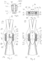
- Fig. 2a shows a sectional view of the frog 10 along a section line AC-AC according to Fig. 1
- the frog insert 20, hereinafter also referred to as the interchangeable frog is embedded in a recess 22 formed in an upper side 24 of the frog block 12. It is provided that an upper side 26 of the interchangeable frog 20 and the upper side 24 of the frog block 12 lie in one plane.
- the interchangeable frog 20 is fastened to the frog block 12 via at least one detachable connection, preferably in the form of clamping or tensioning devices 28, 30, 32, 34.
- clamping or tensioning devices 28, 30, 32, 34 each comprise clamping wedges 34, 36, 38, 40, which are fixed in the frog block 12 by means of clamping screws 42, 44, 46, 48 in corresponding blind hole receptacles or blind hole threads 50, 52, 54, 56.
- An overflow area in crossing 12 is subject to particularly high loads due to its design. To ensure that the service life of the entire crossing 12 is independent of that of the overflow area, the overflow area is designed to be replaceable in the form of the interchangeable crossing 20.
- the interchangeable crossing 20 also enables the overflow area of crossing 10 to be replaced without damaging a ceiling connection. This minimizes costs and ensures largely trouble-free rail traffic. It also allows for extended downtimes and shortened maintenance times.
- the clamping mechanism may become loose due to the varying load acting on the detachable connection when passing over the frog insert. Therefore, the detachable connection 28, 30, 32, 34 must be checked regularly.
- monitoring of the detachable connection 28, 30, 32, 34 for fixing the interchangeable frog 20 to the frog block 12 is carried out by means of a sensor system 58.
- the sensor system 58 detects a signal that is generated when a rail vehicle passes over the interchangeable component in the form of the interchangeable frog 20 and is representative of the quality of the power transmission of the detachable connection 28, 30, 32, 34. If the quality of the power transmission falls below a limit value, a loosening connection or a loosening of the detachable connection 28, 30, 32, 34 is signaled and displayed to a track system operator.
- Fig. 2b shows, by way of example, a section through the clamping device 34 with the clamping wedge 40, wherein the clamping wedge 40 is penetrated by the clamping screw 48, which is screwed into the threaded bore 56 formed in the base component 12, such as a blind hole.
- a clamping disk 41 and a first sealing ring 43 are arranged between a head 48.1 of the clamping screw 48 and an upper side 40.1 of the clamping wedge 40.
- the clamping disk prevents undesired loosening of the clamping screw during operation by means of elastic preload.
- a second sealing ring 45 is preferably arranged between an underside 40.2 of the clamping wedge and the base component. The seal is intended to ensure that the screw connection, ie clamping screw in the blind hole, is protected against corrosion so that the base component can be reused as often as possible when the replaceable component is replaced.
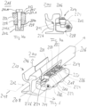
- Fig. 3 shows a top view of the core 10 according to. Fig. 1 , wherein the interchangeable frog 20 is not inserted.
- the sensor system 58 comprises an acceleration sensor which is arranged in the base component in the form of the frog block 12 and is designed such that, when a rail vehicle passes over, it detects at least one acceleration exerted by the possibly insufficiently fastened interchangeable frog 20 on the detachable connection 28, 30, 32, 34 and/or the base component, ie the frog block 12.
- the sensor 58 is fixedly connected to the frog block 12 in a base 60 of the recess 22 such that the sensor detects the signal generated by at least one force exerted on the frog block 12 by the detachable connection 28, 30, 32, 34 and/or the interchangeable frog 20.
- the sensor 58 is not in direct contact with the interchangeable component in the form of the interchangeable frog 20.
- the acceleration sensor 48 is arranged in a groove 64 extending along the longitudinal axis 62 in the bottom 60 of the recess 22.
- a connecting line 66 of the sensor 58 can be led out through a bore 68 formed in the vertical direction along a vertical axis 70.
- the connecting line 66 can be led out laterally from the frog block 12 via a channel 72 along a transverse axis 74.
- This arrangement ensures that the sensor 58 and the connecting line 66 are connected exclusively to the frog block 12 and are spaced apart from the replaceable component in the form of the interchangeable frog 20.
- the arrangement of the sensor 58 below the interchangeable frog 20 ensures effective force transmission from the interchangeable frog 20 or the detachable connection to the sensor 58.
- the replaceable frog 20 allows non-destructive access to the sensor 58 in the covered track.
- the recess 22 with bore 68 also serves as a water drain for the frog block 12.
- Fig. 4 shows a perspective view of the frog 10 with inserted interchangeable frog 20.
- this is provided with a Cover 76, 78 covered.
- the cover 76, 78 lies in a plane spanned by the top side 24 of the frog block 12 and the top side 26 of the interchangeable frog 20.
- Fig. 5 shows an arrangement 80 for monitoring the detachable connections 28, 30, 32, 34 of the frog 10, wherein the replaceable component in the form of the interchangeable frog 20 is connected to the base component in the form of the frog block 12 by means of the detachable connection 28, 30, 32, 34.
- the sensor 58 which is permanently integrated into the frog block 12 or connected thereto, is connected to an evaluation unit 82 via the connecting line 66.
- the sensor 58 which is designed as an acceleration sensor, can detect accelerations in at least one direction, preferably accelerations in three directions, i.e., in the direction of the longitudinal axis 62, the transverse axis 74, and the vertical axis 70.
- the invention is based on the idea that a loose, i.e., insufficiently clamped, replaceable component impacts the base component, i.e., the frog block 12 and/or the detachable connection 28, 30, 32, 34, as the rail vehicle passes over it, thereby generating or causing characteristic accelerations, which are measured by the sensor 58 and subsequently evaluated by the evaluation unit 82, in particular compared with a limit value.
- an alarm signal is generated when the limit value is exceeded, indicating an insufficiently clamped or loose connection 28, 30, 32, 34.
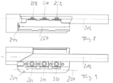
- Fig. 6 shows a perspective view of a second embodiment of a switch component in the form of a tongue rail device 200.
- the tongue rail device 200 comprises a base component in the form of a tongue rail adapter 202, to which a replaceable component in the form of a tongue rail 206 is attached, such as clamped, by means of a detachable connection 204.
- the tongue rail adapter 202 is attached to the base 208 of a grooved rail 210, which is aligned with the tongue rail 206 along the longitudinal axis 212.
- Fig. 7a shows a side view of the tongue rail device 200.
- the tongue rail 206 is subjected to force by means of the detachable connection 204 against a stop 214 of the tongue rail adapter 202.
- the detachable connection 204 comprises The illustrated embodiment includes three clamping elements 216, 218, 220, each consisting of a clamping wedge 222, 224, 226, which can be clamped by means of a screw 228, 230, 232 against a stop 234 of the tongue rail adapter 202 and a side surface 236 of the tongue rail.
- the screws 228, 230, 232 are each received in blind hole threads 238, 240, 242.
- a sensor 244 for monitoring a force transmission or clamping force applied by the detachable connection is integrated into the tongue rail adapter 202.
- the invention is based on the idea that a tongue rail 206 that is loose due to an insufficiently tensioned connection 204 impacts the tongue rail adapter 202 and/or the detachable connection 204 as the rail vehicle passes over it, causing characteristic accelerations that are measured by the sensor and compared with a limit value by an evaluation unit.
- the sensor 244 is designed as an acceleration sensor and measures accelerations in direction and magnitude in a coordinate system spanned by axes 212, 246, 248.
- Fig. 7b shows in detail a section through the clamping element 216 with the clamping wedge 222, wherein the clamping wedge 222 is penetrated by the clamping screw 228, which is screwed into the threaded bore 238 formed in the base component 202, such as a blind hole.
- a clamping washer 223 and a first sealing ring 225 are arranged between a head 228.1 of the clamping screw 228 and an upper side 222.2 of the clamping wedge 222.
- the clamping washer prevents unwanted loosening of the clamping screw during operation by means of elastic preload.
- a second sealing ring 227 is preferably arranged between an underside 228.2 of the clamping wedge and the base component 202.
- the seal is intended to ensure that the screw connection, i.e. the clamping screw in the blind hole, is protected from corrosion so that the base component can be reused as often as possible when the replaceable component is replaced.
- the senor 244 is arranged along an axis 250 (see Fig. 7 and Fig. 8 ) that runs parallel or substantially parallel to the longitudinal axis 212 or the detachable connection 204.
- the sensor 244 can also be arranged below the tongue rail 206 in the tongue rail adapter or below the detachable connection 204.
- the signal detected by the sensor 244 is, as described with reference to Fig. 5 as already described, is fed to an evaluation device.
- the evaluation device comprises a computing unit and a comparator, wherein the signal detected by the sensor is compared as an actual value signal with a reference signal. If a limit value is exceeded, a message is generated indicating a release of the connection 204 or at least one of the clamping devices 216, 218, 202.
Landscapes
- Engineering & Computer Science (AREA)
- Mechanical Engineering (AREA)
- Architecture (AREA)
- Civil Engineering (AREA)
- Structural Engineering (AREA)
- Health & Medical Sciences (AREA)
- Biomedical Technology (AREA)
- General Health & Medical Sciences (AREA)
- Train Traffic Observation, Control, And Security (AREA)
- Machines For Laying And Maintaining Railways (AREA)
- Measurement Of Mechanical Vibrations Or Ultrasonic Waves (AREA)
- Railway Tracks (AREA)
Priority Applications (13)
| Application Number | Priority Date | Filing Date | Title |
|---|---|---|---|
| FIEP22196252.5T FI4339067T3 (fi) | 2022-09-16 | 2022-09-16 | Vaihde- tai risteyskomponentti irrotettavalla liitoksella sekä menetelmä ja järjestelmä liitoksen valvomiseksi |
| EP22196252.5A EP4339067B1 (de) | 2022-09-16 | 2022-09-16 | Weichen- oder kreuzungskomponente mit lösbarer verbindung sowie verfahren und anordnung zur überwachung der lösbaren verbindung |
| DK22196252.5T DK4339067T3 (da) | 2022-09-16 | 2022-09-16 | Sporskifte- eller krydsningskomponent med løsbar forbindelse og fremgangsmåde og indretning til overvågning af den løsbare forbindelse |
| PT221962525T PT4339067T (pt) | 2022-09-16 | 2022-09-16 | Componente de agulha ou de cruzamento com ligação amovível, bem como método e disposição para monitorização da ligação amovível |
| ES22196252T ES3036607T3 (en) | 2022-09-16 | 2022-09-16 | A soft or crossover component with releasable connection and a method and arrangement for monitoring the releasable connection |
| PL22196252.5T PL4339067T3 (pl) | 2022-09-16 | 2022-09-16 | Element rozjazdu lub skrzyżowania z rozłącznym połączeniem oraz sposób i układ monitorowania rozłącznego połączenia |
| AU2023342658A AU2023342658B2 (en) | 2022-09-16 | 2023-09-15 | Points or crossing component with releasable connection and method and arrangement for monitoring the releasable connection |
| EP23768898.1A EP4587312A1 (de) | 2022-09-16 | 2023-09-15 | Weichen- oder kreuzungskomponente mit lösbarer verbindung sowie verfahren und anordnung zur überwachung der lösbaren verbindung |
| IL319587A IL319587A (en) | 2022-09-16 | 2023-09-15 | A transition point or component with a releasable connection and method and an arrangement for monitoring the releasable connection |
| US19/112,556 US20260001579A1 (en) | 2022-09-16 | 2023-09-15 | Points or crossing component with releasable connection and method and arrangement for monitoring the releasable connection |
| PCT/EP2023/075463 WO2024056873A1 (de) | 2022-09-16 | 2023-09-15 | Weichen- oder kreuzungskomponente mit lösbarer verbindung sowie verfahren und anordnung zur überwachung der lösbaren verbindung |
| CN202380065904.XA CN119866294A (zh) | 2022-09-16 | 2023-09-15 | 带有可松脱的连接部的道岔或交叉部件以及用于监控可松脱的连接部的方法和组件 |
| KR1020257010482A KR20250068654A (ko) | 2022-09-16 | 2023-09-15 | 해제 가능한 연결부를 가지는 지점 또는 교차 구성요소 및 해제 가능한 연결부를 모니터링하기 위한 방법 및 장치 |
Applications Claiming Priority (1)
| Application Number | Priority Date | Filing Date | Title |
|---|---|---|---|
| EP22196252.5A EP4339067B1 (de) | 2022-09-16 | 2022-09-16 | Weichen- oder kreuzungskomponente mit lösbarer verbindung sowie verfahren und anordnung zur überwachung der lösbaren verbindung |
Publications (2)
| Publication Number | Publication Date |
|---|---|
| EP4339067A1 EP4339067A1 (de) | 2024-03-20 |
| EP4339067B1 true EP4339067B1 (de) | 2025-04-30 |
Family
ID=83362660
Family Applications (2)
| Application Number | Title | Priority Date | Filing Date |
|---|---|---|---|
| EP22196252.5A Active EP4339067B1 (de) | 2022-09-16 | 2022-09-16 | Weichen- oder kreuzungskomponente mit lösbarer verbindung sowie verfahren und anordnung zur überwachung der lösbaren verbindung |
| EP23768898.1A Pending EP4587312A1 (de) | 2022-09-16 | 2023-09-15 | Weichen- oder kreuzungskomponente mit lösbarer verbindung sowie verfahren und anordnung zur überwachung der lösbaren verbindung |
Family Applications After (1)
| Application Number | Title | Priority Date | Filing Date |
|---|---|---|---|
| EP23768898.1A Pending EP4587312A1 (de) | 2022-09-16 | 2023-09-15 | Weichen- oder kreuzungskomponente mit lösbarer verbindung sowie verfahren und anordnung zur überwachung der lösbaren verbindung |
Country Status (12)
| Country | Link |
|---|---|
| US (1) | US20260001579A1 (pt) |
| EP (2) | EP4339067B1 (pt) |
| KR (1) | KR20250068654A (pt) |
| CN (1) | CN119866294A (pt) |
| AU (1) | AU2023342658B2 (pt) |
| DK (1) | DK4339067T3 (pt) |
| ES (1) | ES3036607T3 (pt) |
| FI (1) | FI4339067T3 (pt) |
| IL (1) | IL319587A (pt) |
| PL (1) | PL4339067T3 (pt) |
| PT (1) | PT4339067T (pt) |
| WO (1) | WO2024056873A1 (pt) |
Family Cites Families (8)
| Publication number | Priority date | Publication date | Assignee | Title |
|---|---|---|---|---|
| FR2745543B1 (fr) | 1996-02-29 | 1998-05-22 | Cogifer | Systeme de telesurveillance pour reseau ferroviaire |
| DE20016674U1 (de) | 2000-09-27 | 2002-02-14 | Hanning & Kahl GmbH & Co., 33813 Oerlinghausen | Anordnung zur Messung des Anfahrens einer Herzspitze einer Weiche |
| DE102004014282C5 (de) | 2004-03-22 | 2008-06-12 | Db Netz Ag | Diagnose und Zustandsmonitoring im Überlaufbereich von Weichen, starren Herzstücken und Kreuzungen |
| CZ18503U1 (cs) * | 2008-03-18 | 2008-04-28 | DT- Výhybkárna a strojírna a. s. | Srdcovka |
| DE102009033980B4 (de) * | 2009-07-16 | 2013-08-01 | Siemens Aktiengesellschaft | Spurgebundenes Fahrzeug |
| DE102010037110A1 (de) | 2010-05-12 | 2011-11-17 | Voestalpine Bwg Gmbh & Co. Kg | Oberbauvorrichtung |
| AT521420A1 (de) * | 2018-07-11 | 2020-01-15 | Plasser & Theurer Export Von Bahnbaumaschinen Gmbh | Verfahren und System zum Überwachen einer Gleisstrecke |
| NL2027749B1 (en) * | 2021-03-12 | 2022-09-27 | Rail 1435 Tech B V | A railway monitoring sensor unit |
-
2022
- 2022-09-16 FI FIEP22196252.5T patent/FI4339067T3/fi active
- 2022-09-16 EP EP22196252.5A patent/EP4339067B1/de active Active
- 2022-09-16 DK DK22196252.5T patent/DK4339067T3/da active
- 2022-09-16 PT PT221962525T patent/PT4339067T/pt unknown
- 2022-09-16 ES ES22196252T patent/ES3036607T3/es active Active
- 2022-09-16 PL PL22196252.5T patent/PL4339067T3/pl unknown
-
2023
- 2023-09-15 KR KR1020257010482A patent/KR20250068654A/ko active Pending
- 2023-09-15 WO PCT/EP2023/075463 patent/WO2024056873A1/de not_active Ceased
- 2023-09-15 AU AU2023342658A patent/AU2023342658B2/en active Active
- 2023-09-15 EP EP23768898.1A patent/EP4587312A1/de active Pending
- 2023-09-15 US US19/112,556 patent/US20260001579A1/en active Pending
- 2023-09-15 IL IL319587A patent/IL319587A/en unknown
- 2023-09-15 CN CN202380065904.XA patent/CN119866294A/zh active Pending
Also Published As
| Publication number | Publication date |
|---|---|
| FI4339067T3 (fi) | 2025-07-15 |
| AU2023342658A1 (en) | 2025-03-20 |
| KR20250068654A (ko) | 2025-05-16 |
| WO2024056873A1 (de) | 2024-03-21 |
| PT4339067T (pt) | 2025-07-30 |
| EP4587312A1 (de) | 2025-07-23 |
| ES3036607T3 (en) | 2025-09-22 |
| DK4339067T3 (da) | 2025-08-04 |
| EP4339067A1 (de) | 2024-03-20 |
| CN119866294A (zh) | 2025-04-22 |
| PL4339067T3 (pl) | 2025-09-08 |
| AU2023342658B2 (en) | 2025-08-07 |
| US20260001579A1 (en) | 2026-01-01 |
| IL319587A (en) | 2025-05-01 |
Similar Documents
| Publication | Publication Date | Title |
|---|---|---|
| EP0344145B1 (de) | Einrichtung zum Erfassen des Zustandes von Schienenweichen oder Kreuzungen | |
| AT510295B1 (de) | Vorrichtung zum erkennen von relativbewegungen in einem fahrzeug | |
| EP3116762B1 (de) | Vorrichtung zur hinderniserkennung bei schienenfahrzeugen | |
| DE102008058244A1 (de) | System zur Analyse des Fahrwerkzustands bei Schienenfahrzeugen | |
| EP1904356B1 (de) | Verfahren und vorrichtung zur erfassung der entgleisungsgefahr von schienenfahrzeugen | |
| EP4339067B1 (de) | Weichen- oder kreuzungskomponente mit lösbarer verbindung sowie verfahren und anordnung zur überwachung der lösbaren verbindung | |
| DE10241320A1 (de) | Vorrichtung zur Erfassung von Veränderungen an Eisenbahnrädern im Betriebseinsatz | |
| WO2000009378A1 (de) | Verfahren zur erkennung von schäden an schienenfahrzeugen und/oder gleisen | |
| CH682140A5 (pt) | ||
| DE102008008578B3 (de) | Ermittlung der dynamischen Radkraft eines Eisenbahnfahrzeugs auf das Herzstück einer Weiche | |
| DE202010010698U1 (de) | Vorrichtung zur Endlagenprüfung von beweglichen Teilen einer Schienenweiche | |
| DE102021103068B4 (de) | Bremsbelagsystem und Sensoreinheit | |
| CH679950A5 (en) | Railway line or beam force measurement appts. | |
| BR112025004732B1 (pt) | Componente de pontos ou cruzamento com conexão liberável e método e arranjo para monitoramento da conexão liberável | |
| DE10009156C1 (de) | Verfahren und Vorrichtung zum Ermitteln der Eigenschaften der Radfederung eines Drehgestells von Schienenfahrzeugen | |
| EP3676449B1 (de) | Betonschwelle für einen eisenbahnfahrweg | |
| CA3267039A1 (en) | Points or crossing component with releasable connection and method and arrangement for monitoring the releasable connection | |
| DE102015009205A1 (de) | Schwelle zur Messung von Radaufstandskräften | |
| AT396843B (de) | Einrichtung zum erfassen des zustandes von schienenweichen oder kreuzungen | |
| DE102011086356A1 (de) | Verfahren und Vorrichtung zur Überwachung der Stabilität einer mechanischen Verbindung | |
| DE20016674U1 (de) | Anordnung zur Messung des Anfahrens einer Herzspitze einer Weiche | |
| EP1520075A1 (de) | Einrichtung zur messung der absenking bzw. setzung des eisenbahnoberbaues | |
| WO2025181340A1 (de) | Verfahren zur durchführung von inspektionen von sicherheitsrelevanten zuständen | |
| DE29823409U1 (de) | Einrichtung zur Überwachung von Spurwechselvorgängen | |
| DE102007037751A1 (de) | System zum Befestigen einer Schiene für ein Schienenfahrzeug auf einem festen Untergrund |
Legal Events
| Date | Code | Title | Description |
|---|---|---|---|
| PUAI | Public reference made under article 153(3) epc to a published international application that has entered the european phase |
Free format text: ORIGINAL CODE: 0009012 |
|
| STAA | Information on the status of an ep patent application or granted ep patent |
Free format text: STATUS: REQUEST FOR EXAMINATION WAS MADE |
|
| STAA | Information on the status of an ep patent application or granted ep patent |
Free format text: STATUS: EXAMINATION IS IN PROGRESS |
|
| 17P | Request for examination filed |
Effective date: 20240207 |
|
| AK | Designated contracting states |
Kind code of ref document: A1 Designated state(s): AL AT BE BG CH CY CZ DE DK EE ES FI FR GB GR HR HU IE IS IT LI LT LU LV MC MK MT NL NO PL PT RO RS SE SI SK SM TR |
|
| 17Q | First examination report despatched |
Effective date: 20240315 |
|
| GRAP | Despatch of communication of intention to grant a patent |
Free format text: ORIGINAL CODE: EPIDOSNIGR1 |
|
| STAA | Information on the status of an ep patent application or granted ep patent |
Free format text: STATUS: GRANT OF PATENT IS INTENDED |
|
| INTG | Intention to grant announced |
Effective date: 20240813 |
|
| GRAJ | Information related to disapproval of communication of intention to grant by the applicant or resumption of examination proceedings by the epo deleted |
Free format text: ORIGINAL CODE: EPIDOSDIGR1 |
|
| STAA | Information on the status of an ep patent application or granted ep patent |
Free format text: STATUS: EXAMINATION IS IN PROGRESS |
|
| RAP1 | Party data changed (applicant data changed or rights of an application transferred) |
Owner name: VOESTALPINE RAILWAY SYSTEMS GMBH Owner name: VOESTALPINE TURNOUT TECHNOLOGY GERMANY GMBH |
|
| INTC | Intention to grant announced (deleted) | ||
| GRAS | Grant fee paid |
Free format text: ORIGINAL CODE: EPIDOSNIGR3 |
|
| STAA | Information on the status of an ep patent application or granted ep patent |
Free format text: STATUS: GRANT OF PATENT IS INTENDED |
|
| GRAP | Despatch of communication of intention to grant a patent |
Free format text: ORIGINAL CODE: EPIDOSNIGR1 |
|
| GRAA | (expected) grant |
Free format text: ORIGINAL CODE: 0009210 |
|
| STAA | Information on the status of an ep patent application or granted ep patent |
Free format text: STATUS: THE PATENT HAS BEEN GRANTED |
|
| INTG | Intention to grant announced |
Effective date: 20250227 |
|
| AK | Designated contracting states |
Kind code of ref document: B1 Designated state(s): AL AT BE BG CH CY CZ DE DK EE ES FI FR GB GR HR HU IE IS IT LI LT LU LV MC MK MT NL NO PL PT RO RS SE SI SK SM TR |
|
| REG | Reference to a national code |
Ref country code: CH Ref legal event code: EP Ref country code: GB Ref legal event code: FG4D Free format text: NOT ENGLISH |
|
| REG | Reference to a national code |
Ref country code: IE Ref legal event code: FG4D Free format text: LANGUAGE OF EP DOCUMENT: GERMAN |
|
| REG | Reference to a national code |
Ref country code: DE Ref legal event code: R096 Ref document number: 502022003742 Country of ref document: DE |
|
| P01 | Opt-out of the competence of the unified patent court (upc) registered |
Free format text: CASE NUMBER: APP_20088/2025 Effective date: 20250428 |
|
| REG | Reference to a national code |
Ref country code: FI Ref legal event code: FGE |
|
| REG | Reference to a national code |
Ref country code: NL Ref legal event code: FP Ref country code: PT Ref legal event code: SC4A Ref document number: 4339067 Country of ref document: PT Date of ref document: 20250730 Kind code of ref document: T Free format text: AVAILABILITY OF NATIONAL TRANSLATION Effective date: 20250723 |
|
| REG | Reference to a national code |
Ref country code: DK Ref legal event code: T3 Effective date: 20250728 |
|
| REG | Reference to a national code |
Ref country code: ES Ref legal event code: FG2A Ref document number: 3036607 Country of ref document: ES Kind code of ref document: T3 Effective date: 20250922 |
|
| REG | Reference to a national code |
Ref country code: CH Ref legal event code: U11 Free format text: ST27 STATUS EVENT CODE: U-0-0-U10-U11 (AS PROVIDED BY THE NATIONAL OFFICE) Effective date: 20251001 |
|
| PGFP | Annual fee paid to national office [announced via postgrant information from national office to epo] |
Ref country code: PT Payment date: 20250904 Year of fee payment: 4 Ref country code: FI Payment date: 20250926 Year of fee payment: 4 |
|
| PGFP | Annual fee paid to national office [announced via postgrant information from national office to epo] |
Ref country code: DE Payment date: 20250919 Year of fee payment: 4 Ref country code: DK Payment date: 20250923 Year of fee payment: 4 |
|
| REG | Reference to a national code |
Ref country code: LT Ref legal event code: MG9D |
|
| PG25 | Lapsed in a contracting state [announced via postgrant information from national office to epo] |
Ref country code: GR Free format text: LAPSE BECAUSE OF FAILURE TO SUBMIT A TRANSLATION OF THE DESCRIPTION OR TO PAY THE FEE WITHIN THE PRESCRIBED TIME-LIMIT Effective date: 20250731 |
|
| PGFP | Annual fee paid to national office [announced via postgrant information from national office to epo] |
Ref country code: NO Payment date: 20250923 Year of fee payment: 4 |
|
| PGFP | Annual fee paid to national office [announced via postgrant information from national office to epo] |
Ref country code: TR Payment date: 20250909 Year of fee payment: 4 Ref country code: PL Payment date: 20250821 Year of fee payment: 4 Ref country code: NL Payment date: 20250918 Year of fee payment: 4 |
|
| PG25 | Lapsed in a contracting state [announced via postgrant information from national office to epo] |
Ref country code: BG Free format text: LAPSE BECAUSE OF FAILURE TO SUBMIT A TRANSLATION OF THE DESCRIPTION OR TO PAY THE FEE WITHIN THE PRESCRIBED TIME-LIMIT Effective date: 20250430 |
|
| PGFP | Annual fee paid to national office [announced via postgrant information from national office to epo] |
Ref country code: BE Payment date: 20250918 Year of fee payment: 4 |
|
| PG25 | Lapsed in a contracting state [announced via postgrant information from national office to epo] |
Ref country code: HR Free format text: LAPSE BECAUSE OF FAILURE TO SUBMIT A TRANSLATION OF THE DESCRIPTION OR TO PAY THE FEE WITHIN THE PRESCRIBED TIME-LIMIT Effective date: 20250430 |
|
| PGFP | Annual fee paid to national office [announced via postgrant information from national office to epo] |
Ref country code: AT Payment date: 20251020 Year of fee payment: 4 Ref country code: FR Payment date: 20250922 Year of fee payment: 4 |
|
| PG25 | Lapsed in a contracting state [announced via postgrant information from national office to epo] |
Ref country code: RS Free format text: LAPSE BECAUSE OF FAILURE TO SUBMIT A TRANSLATION OF THE DESCRIPTION OR TO PAY THE FEE WITHIN THE PRESCRIBED TIME-LIMIT Effective date: 20250731 |
|
| PGFP | Annual fee paid to national office [announced via postgrant information from national office to epo] |
Ref country code: IE Payment date: 20250918 Year of fee payment: 4 |
|
| PG25 | Lapsed in a contracting state [announced via postgrant information from national office to epo] |
Ref country code: IS Free format text: LAPSE BECAUSE OF FAILURE TO SUBMIT A TRANSLATION OF THE DESCRIPTION OR TO PAY THE FEE WITHIN THE PRESCRIBED TIME-LIMIT Effective date: 20250830 |
|
| PG25 | Lapsed in a contracting state [announced via postgrant information from national office to epo] |
Ref country code: LV Free format text: LAPSE BECAUSE OF FAILURE TO SUBMIT A TRANSLATION OF THE DESCRIPTION OR TO PAY THE FEE WITHIN THE PRESCRIBED TIME-LIMIT Effective date: 20250430 |
|
| PG25 | Lapsed in a contracting state [announced via postgrant information from national office to epo] |
Ref country code: SM Free format text: LAPSE BECAUSE OF FAILURE TO SUBMIT A TRANSLATION OF THE DESCRIPTION OR TO PAY THE FEE WITHIN THE PRESCRIBED TIME-LIMIT Effective date: 20250430 |
|
| PGFP | Annual fee paid to national office [announced via postgrant information from national office to epo] |
Ref country code: IT Payment date: 20250930 Year of fee payment: 4 |
|
| PGFP | Annual fee paid to national office [announced via postgrant information from national office to epo] |
Ref country code: CH Payment date: 20251001 Year of fee payment: 4 |
|
| PG25 | Lapsed in a contracting state [announced via postgrant information from national office to epo] |
Ref country code: CZ Free format text: LAPSE BECAUSE OF FAILURE TO SUBMIT A TRANSLATION OF THE DESCRIPTION OR TO PAY THE FEE WITHIN THE PRESCRIBED TIME-LIMIT Effective date: 20250430 |
|
| PG25 | Lapsed in a contracting state [announced via postgrant information from national office to epo] |
Ref country code: EE Free format text: LAPSE BECAUSE OF FAILURE TO SUBMIT A TRANSLATION OF THE DESCRIPTION OR TO PAY THE FEE WITHIN THE PRESCRIBED TIME-LIMIT Effective date: 20250430 |
|
| PG25 | Lapsed in a contracting state [announced via postgrant information from national office to epo] |
Ref country code: SK Free format text: LAPSE BECAUSE OF FAILURE TO SUBMIT A TRANSLATION OF THE DESCRIPTION OR TO PAY THE FEE WITHIN THE PRESCRIBED TIME-LIMIT Effective date: 20250430 |
|
| PGFP | Annual fee paid to national office [announced via postgrant information from national office to epo] |
Ref country code: ES Payment date: 20251030 Year of fee payment: 4 |
|
| REG | Reference to a national code |
Ref country code: DE Ref legal event code: R097 Ref document number: 502022003742 Country of ref document: DE |
|
| VS25 | Lapsed in a validation state [announced via postgrant information from nat. office to epo] |
Ref country code: MA Free format text: FAILURE TO ELECT DOMICILE IN THE NATIONAL COUNTRY Effective date: 20250801 |
|
| PG25 | Lapsed in a contracting state [announced via postgrant information from national office to epo] |
Ref country code: RO Free format text: LAPSE BECAUSE OF FAILURE TO SUBMIT A TRANSLATION OF THE DESCRIPTION OR TO PAY THE FEE WITHIN THE PRESCRIBED TIME-LIMIT Effective date: 20250430 |
|
| PLBE | No opposition filed within time limit |
Free format text: ORIGINAL CODE: 0009261 |
|
| STAA | Information on the status of an ep patent application or granted ep patent |
Free format text: STATUS: NO OPPOSITION FILED WITHIN TIME LIMIT |
|
| REG | Reference to a national code |
Ref country code: CH Ref legal event code: L10 Free format text: ST27 STATUS EVENT CODE: U-0-0-L10-L00 (AS PROVIDED BY THE NATIONAL OFFICE) Effective date: 20260311 |
|
| VS25 | Lapsed in a validation state [announced via postgrant information from nat. office to epo] |
Ref country code: MA Free format text: LAPSE BECAUSE OF FAILURE TO SUBMIT A TRANSLATION OF THE DESCRIPTION OR TO PAY THE FEE WITHIN THE PRESCRIBED TIME-LIMIT Effective date: 20250430 |
|
| 26N | No opposition filed |
Effective date: 20260202 |