EP4339067B1 - A soft or crossover component with releasable connection and a method and arrangement for monitoring the releasable connection - Google Patents
A soft or crossover component with releasable connection and a method and arrangement for monitoring the releasable connection Download PDFInfo
- Publication number
- EP4339067B1 EP4339067B1 EP22196252.5A EP22196252A EP4339067B1 EP 4339067 B1 EP4339067 B1 EP 4339067B1 EP 22196252 A EP22196252 A EP 22196252A EP 4339067 B1 EP4339067 B1 EP 4339067B1
- Authority
- EP
- European Patent Office
- Prior art keywords
- component
- sensor
- frog
- detachable connection
- switch
- Prior art date
- Legal status (The legal status is an assumption and is not a legal conclusion. Google has not performed a legal analysis and makes no representation as to the accuracy of the status listed.)
- Active
Links
Images

Classifications
-
- B—PERFORMING OPERATIONS; TRANSPORTING
- B61—RAILWAYS
- B61L—GUIDING RAILWAY TRAFFIC; ENSURING THE SAFETY OF RAILWAY TRAFFIC
- B61L23/00—Control, warning or like safety means along the route or between vehicles or trains
- B61L23/04—Control, warning or like safety means along the route or between vehicles or trains for monitoring the mechanical state of the route
- B61L23/042—Track changes detection
- B61L23/045—Rail wear
-
- B—PERFORMING OPERATIONS; TRANSPORTING
- B61—RAILWAYS
- B61L—GUIDING RAILWAY TRAFFIC; ENSURING THE SAFETY OF RAILWAY TRAFFIC
- B61L23/00—Control, warning or like safety means along the route or between vehicles or trains
- B61L23/04—Control, warning or like safety means along the route or between vehicles or trains for monitoring the mechanical state of the route
- B61L23/042—Track changes detection
- B61L23/047—Track or rail movements
-
- B—PERFORMING OPERATIONS; TRANSPORTING
- B61—RAILWAYS
- B61L—GUIDING RAILWAY TRAFFIC; ENSURING THE SAFETY OF RAILWAY TRAFFIC
- B61L27/00—Central railway traffic control systems; Trackside control; Communication systems specially adapted therefor
- B61L27/50—Trackside diagnosis or maintenance, e.g. software upgrades
- B61L27/53—Trackside diagnosis or maintenance, e.g. software upgrades for trackside elements or systems, e.g. trackside supervision of trackside control system conditions
-
- E—FIXED CONSTRUCTIONS
- E01—CONSTRUCTION OF ROADS, RAILWAYS, OR BRIDGES
- E01B—PERMANENT WAY; PERMANENT-WAY TOOLS; MACHINES FOR MAKING RAILWAYS OF ALL KINDS
- E01B7/00—Switches; Crossings
- E01B7/10—Frogs
- E01B7/12—Fixed frogs made of one part or composite
Definitions
- the present invention relates to a switch or crossing component in the form of a frog or a tongue rail device, comprising a base component in the form of a frog block or tongue rail adapter, a replaceable component in the form of a frog insert or a tongue rail, at least one detachable connection, such as a screw connection or clamping, by means of which the replaceable component can be connected to the base component, in particular in a force-fitting and/or form-fitting manner.
- the invention also relates to a method for monitoring a detachable connection of a switch or crossing component in the form of a frog or a tongue rail device, wherein by means of the detachable connection a replaceable component in the form of a frog insert or a tongue rail is fastened to a base component in the form of a frog block or a tongue rail adapter and wherein by means of a sensor a signal for checking the quality, in particular the force transmission or the form fit, of the detachable connection is detected, which signal is generated when a rail vehicle passes over the switch or crossing component and is representative of the quality of the detachable connection,
- a remote monitoring system for a railway network for monitoring operating parameters of at least one switch system of the railway network is known.
- Each switch system is designed to include a set of sensors, each adapted to measure a property value representative of a particular property.
- the sensors are each connected to a data acquisition unit that stores an algorithm for managing the acquired measurement data.
- means are provided for comparing the measured data with at least one threshold value which is representative of the limit value for a corresponding operating parameter.
- the known arrangement includes, for example, a replaceable component in the form of a check rail, which is connected to a base component in the form of a track via a detachable connection.
- a sensor is provided to monitor the clamping of the check rail to the track, which is achieved by the detachable connection.
- This sensor is located in the check rail, which means that when the check rail is replaced, the sensor must also be replaced or dismantled. This involves increased effort.
- the method also provides for monitoring the quality of the clamping of the check rail using measurement signals supplied by an acceleration sensor which detects the shocks generated by a wheel on the check rail.
- the DE 200 16 674 U1 concerns a system for measuring the approach to the frog point of a switch.
- the system is characterized by a structure-borne noise sensor that is inserted into the frog of the switch or a component connected to this frog. If the switch is approached at an acute angle and the flange of a wheel hits the frog point due to misalignment or wear on one of the check rails, a violent shock occurs, with the resulting structure-borne noise pulse being transmitted through the base plate of the frog to the wing rail firmly screwed to it and thus registered by the structure-borne noise sensor.
- the sensor is located laterally in a wing rail and would be inaccessible on tracks that are typically covered in trams.
- the DE 10 2004 014 282 B4 relates to a method for diagnosis and condition monitoring in the overrun area of a switch and/or a crossing and/or a crossing switch of a railway line.
- a measurement of the acceleration of the switch or the crossing point is carried out at the rigid frog or at the crossing point at at least one location on the frog or crossing point in at least one spatial direction, which acceleration is generated by the train passing over the switch or the crossing point.
- a detachable connection is not monitored.
- the present invention is based on the object of developing a switch or crossing component, a method, or an arrangement of the type mentioned above in such a way that the monitoring of a detachable connection, such as the fastening or clamping of replaceable components, is simplified and improved using sensors.
- a loose screw connection/clamp should be reliably signaled/detected.
- the replacement of a defective replaceable component should be possible without major effort.
- a switch or crossing component of the type mentioned at the outset in that the switch or crossing component has at least one sensor for monitoring the quality of the detachable connection, which sensor is arranged in the base component and firmly connected thereto, wherein a signal is generated in the sensor when a rail vehicle passes over the switch or crossing component, which signal is representative of the quality of the detachable connection.
- the senor In order to enable a simple replacement of a defective sensor or a component to be replaced, i.e. without destroying a track covering or without dismantling the intact sensor from the component to be replaced, the sensor is arranged in the base component and firmly connected to it.
- both the sensor and the supply line remain unaffected by the change of component, as the sensor is not in contact with the replaceable component.
- the senor is preferably designed as an acceleration sensor or structure-borne sound sensor.
- the senor is arranged in the base component for transmitting accelerations and mechanical vibrations such that when a rail vehicle passes over it, in particular over an insufficiently fastened replaceable component, it detects at least one impact exerted by the insufficiently fastened replaceable component on the at least one detachable connection and/or the base component as an acceleration and/or mechanical vibration.
- the switch or crossing component is a frog
- the base component is a frog block
- the replaceable component is a frog insert, which is connected to the frog block by means of the detachable connection, preferably in the form of a screwable clamp connection.
- the frog insert is arranged in a recess of the frog block which is non-destructively accessible when the frog is covered, wherein the sensor is arranged in the recess, preferably in the vertical direction below the replaceable frog insert, and is preferably covered by it without contact with the sensor.
- the sensor is arranged in a groove formed in a bottom of the recess, wherein the groove forms at least a portion of a water drain and opens into a drain.
- a further preferred embodiment is characterized in that the base component is a tongue adapter and the replaceable component is a tongue rail, which is detachable connection in the form of a screwable clamp connection with the tongue adapter.
- the detachable connection preferably has at least one clamping wedge, wherein the clamping wedge is penetrated by a clamping screw which can be screwed into a thread formed in the base component, preferably a blind hole thread.
- a clamping washer and a first sealing ring are arranged between a head of the clamping screw and an upper side of the clamping wedge.
- a second sealing ring can preferably be arranged between an underside of the clamping wedge and the base component.
- the invention relates to a method for monitoring a detachable connection of a switch or crossing component in the form of a frog or a tongue rail device, wherein by means of the detachable connection a replaceable component in the form of a frog insert or a tongue rail is fastened to a base component in the form of a frog block or a tongue rail adapter, and wherein by means of a sensor a signal for checking the quality, in particular the power transmission and/or the positive connection, of the detachable connection is detected, which signal is generated when a rail vehicle drives over the switch or crossing component, in particular the replaceable component, and is representative of the quality of the detachable connection.
- the signal is generated when the rail vehicle passes over the replaceable component by at least one impact exerted by the replaceable component on the detachable connection and/or on the base component and is detected by the sensor arranged in the base component.
- the signals generated when the rail vehicle passes over due to a relative movement or a displacement of the replaceable component and/or due to a replaceable component displaced from the optimal position with respect to the detachable connection and/or the base component are evaluated.
- an acceleration sensor or a structure-borne noise sensor is preferably used as the sensor.
- the sensor detects at least one characteristic acceleration or characteristic structure-borne noise exerted by an inadequately secured replaceable component on the at least one detachable connection and/or base component.
- a further development provides for the signal generated by the rail vehicle's passage to be compared as an actual value signal with a reference signal or a limit value in order to detect a signal exhibiting the characteristic acceleration or the characteristic structure-borne noise. If the actual value signal deviates from the reference signal or the limit value, a message is generated indicating insufficient quality of the force transmission and/or the form closure of the detachable connection.
- At least two measurements are carried out during one crossing of the rail vehicle or during two consecutive rail vehicles and the message is only triggered if at least two events are detected per crossing or consecutive crossings, the event being the detection of a characteristic signal.
- the invention relates to an arrangement with a switch or crossing component of the type described above, wherein the arrangement has an evaluation unit which is connected to the at least one sensor.
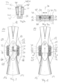
- Fig. 2a shows a sectional view of the frog 10 along a section line AC-AC according to Fig. 1
- the frog insert 20, hereinafter also referred to as the interchangeable frog is embedded in a recess 22 formed in an upper side 24 of the frog block 12. It is provided that an upper side 26 of the interchangeable frog 20 and the upper side 24 of the frog block 12 lie in one plane.
- the interchangeable frog 20 is fastened to the frog block 12 via at least one detachable connection, preferably in the form of clamping or tensioning devices 28, 30, 32, 34.
- clamping or tensioning devices 28, 30, 32, 34 each comprise clamping wedges 34, 36, 38, 40, which are fixed in the frog block 12 by means of clamping screws 42, 44, 46, 48 in corresponding blind hole receptacles or blind hole threads 50, 52, 54, 56.
- An overflow area in crossing 12 is subject to particularly high loads due to its design. To ensure that the service life of the entire crossing 12 is independent of that of the overflow area, the overflow area is designed to be replaceable in the form of the interchangeable crossing 20.
- the interchangeable crossing 20 also enables the overflow area of crossing 10 to be replaced without damaging a ceiling connection. This minimizes costs and ensures largely trouble-free rail traffic. It also allows for extended downtimes and shortened maintenance times.
- the clamping mechanism may become loose due to the varying load acting on the detachable connection when passing over the frog insert. Therefore, the detachable connection 28, 30, 32, 34 must be checked regularly.
- monitoring of the detachable connection 28, 30, 32, 34 for fixing the interchangeable frog 20 to the frog block 12 is carried out by means of a sensor system 58.
- the sensor system 58 detects a signal that is generated when a rail vehicle passes over the interchangeable component in the form of the interchangeable frog 20 and is representative of the quality of the power transmission of the detachable connection 28, 30, 32, 34. If the quality of the power transmission falls below a limit value, a loosening connection or a loosening of the detachable connection 28, 30, 32, 34 is signaled and displayed to a track system operator.
- Fig. 2b shows, by way of example, a section through the clamping device 34 with the clamping wedge 40, wherein the clamping wedge 40 is penetrated by the clamping screw 48, which is screwed into the threaded bore 56 formed in the base component 12, such as a blind hole.
- a clamping disk 41 and a first sealing ring 43 are arranged between a head 48.1 of the clamping screw 48 and an upper side 40.1 of the clamping wedge 40.
- the clamping disk prevents undesired loosening of the clamping screw during operation by means of elastic preload.
- a second sealing ring 45 is preferably arranged between an underside 40.2 of the clamping wedge and the base component. The seal is intended to ensure that the screw connection, ie clamping screw in the blind hole, is protected against corrosion so that the base component can be reused as often as possible when the replaceable component is replaced.
- Fig. 3 shows a top view of the core 10 according to. Fig. 1 , wherein the interchangeable frog 20 is not inserted.
- the sensor system 58 comprises an acceleration sensor which is arranged in the base component in the form of the frog block 12 and is designed such that, when a rail vehicle passes over, it detects at least one acceleration exerted by the possibly insufficiently fastened interchangeable frog 20 on the detachable connection 28, 30, 32, 34 and/or the base component, ie the frog block 12.
- the sensor 58 is fixedly connected to the frog block 12 in a base 60 of the recess 22 such that the sensor detects the signal generated by at least one force exerted on the frog block 12 by the detachable connection 28, 30, 32, 34 and/or the interchangeable frog 20.
- the sensor 58 is not in direct contact with the interchangeable component in the form of the interchangeable frog 20.
- the acceleration sensor 48 is arranged in a groove 64 extending along the longitudinal axis 62 in the bottom 60 of the recess 22.
- a connecting line 66 of the sensor 58 can be led out through a bore 68 formed in the vertical direction along a vertical axis 70.
- the connecting line 66 can be led out laterally from the frog block 12 via a channel 72 along a transverse axis 74.
- This arrangement ensures that the sensor 58 and the connecting line 66 are connected exclusively to the frog block 12 and are spaced apart from the replaceable component in the form of the interchangeable frog 20.
- the arrangement of the sensor 58 below the interchangeable frog 20 ensures effective force transmission from the interchangeable frog 20 or the detachable connection to the sensor 58.
- the replaceable frog 20 allows non-destructive access to the sensor 58 in the covered track.
- the recess 22 with bore 68 also serves as a water drain for the frog block 12.
- Fig. 4 shows a perspective view of the frog 10 with inserted interchangeable frog 20.
- this is provided with a Cover 76, 78 covered.
- the cover 76, 78 lies in a plane spanned by the top side 24 of the frog block 12 and the top side 26 of the interchangeable frog 20.
- Fig. 5 shows an arrangement 80 for monitoring the detachable connections 28, 30, 32, 34 of the frog 10, wherein the replaceable component in the form of the interchangeable frog 20 is connected to the base component in the form of the frog block 12 by means of the detachable connection 28, 30, 32, 34.
- the sensor 58 which is permanently integrated into the frog block 12 or connected thereto, is connected to an evaluation unit 82 via the connecting line 66.
- the sensor 58 which is designed as an acceleration sensor, can detect accelerations in at least one direction, preferably accelerations in three directions, i.e., in the direction of the longitudinal axis 62, the transverse axis 74, and the vertical axis 70.
- the invention is based on the idea that a loose, i.e., insufficiently clamped, replaceable component impacts the base component, i.e., the frog block 12 and/or the detachable connection 28, 30, 32, 34, as the rail vehicle passes over it, thereby generating or causing characteristic accelerations, which are measured by the sensor 58 and subsequently evaluated by the evaluation unit 82, in particular compared with a limit value.
- an alarm signal is generated when the limit value is exceeded, indicating an insufficiently clamped or loose connection 28, 30, 32, 34.
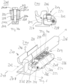
- Fig. 6 shows a perspective view of a second embodiment of a switch component in the form of a tongue rail device 200.
- the tongue rail device 200 comprises a base component in the form of a tongue rail adapter 202, to which a replaceable component in the form of a tongue rail 206 is attached, such as clamped, by means of a detachable connection 204.
- the tongue rail adapter 202 is attached to the base 208 of a grooved rail 210, which is aligned with the tongue rail 206 along the longitudinal axis 212.
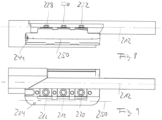
- Fig. 7a shows a side view of the tongue rail device 200.
- the tongue rail 206 is subjected to force by means of the detachable connection 204 against a stop 214 of the tongue rail adapter 202.
- the detachable connection 204 comprises The illustrated embodiment includes three clamping elements 216, 218, 220, each consisting of a clamping wedge 222, 224, 226, which can be clamped by means of a screw 228, 230, 232 against a stop 234 of the tongue rail adapter 202 and a side surface 236 of the tongue rail.
- the screws 228, 230, 232 are each received in blind hole threads 238, 240, 242.
- a sensor 244 for monitoring a force transmission or clamping force applied by the detachable connection is integrated into the tongue rail adapter 202.
- the invention is based on the idea that a tongue rail 206 that is loose due to an insufficiently tensioned connection 204 impacts the tongue rail adapter 202 and/or the detachable connection 204 as the rail vehicle passes over it, causing characteristic accelerations that are measured by the sensor and compared with a limit value by an evaluation unit.
- the sensor 244 is designed as an acceleration sensor and measures accelerations in direction and magnitude in a coordinate system spanned by axes 212, 246, 248.
- Fig. 7b shows in detail a section through the clamping element 216 with the clamping wedge 222, wherein the clamping wedge 222 is penetrated by the clamping screw 228, which is screwed into the threaded bore 238 formed in the base component 202, such as a blind hole.
- a clamping washer 223 and a first sealing ring 225 are arranged between a head 228.1 of the clamping screw 228 and an upper side 222.2 of the clamping wedge 222.
- the clamping washer prevents unwanted loosening of the clamping screw during operation by means of elastic preload.
- a second sealing ring 227 is preferably arranged between an underside 228.2 of the clamping wedge and the base component 202.
- the seal is intended to ensure that the screw connection, i.e. the clamping screw in the blind hole, is protected from corrosion so that the base component can be reused as often as possible when the replaceable component is replaced.
- the senor 244 is arranged along an axis 250 (see Fig. 7 and Fig. 8 ) that runs parallel or substantially parallel to the longitudinal axis 212 or the detachable connection 204.
- the sensor 244 can also be arranged below the tongue rail 206 in the tongue rail adapter or below the detachable connection 204.
- the signal detected by the sensor 244 is, as described with reference to Fig. 5 as already described, is fed to an evaluation device.
- the evaluation device comprises a computing unit and a comparator, wherein the signal detected by the sensor is compared as an actual value signal with a reference signal. If a limit value is exceeded, a message is generated indicating a release of the connection 204 or at least one of the clamping devices 216, 218, 202.
Landscapes
- Engineering & Computer Science (AREA)
- Mechanical Engineering (AREA)
- Architecture (AREA)
- Civil Engineering (AREA)
- Structural Engineering (AREA)
- Health & Medical Sciences (AREA)
- Biomedical Technology (AREA)
- General Health & Medical Sciences (AREA)
- Train Traffic Observation, Control, And Security (AREA)
- Machines For Laying And Maintaining Railways (AREA)
- Measurement Of Mechanical Vibrations Or Ultrasonic Waves (AREA)
- Railway Tracks (AREA)
Description
Die vorliegende Erfindung bezieht sich auf eine Weichen- oder Kreuzungskomponente in Form eines Herzstücks oder einer Zungenschienenvorrichtung, umfassend eine Basiskomponente in Form eines Herzstückblocks oder Zungenschienenadapters, eine auswechselbare Komponente in Form eines Herzstückeinsatzes oder einer Zungenschiene, zumindest eine lösbare Verbindung, wie Verschraubung oder Klemmung, mittels der die auswechselbare Komponente mit der Basiskomponente, insbesondere kraftschlüssig und/oder formschlüssig, verbindbar ist.The present invention relates to a switch or crossing component in the form of a frog or a tongue rail device, comprising a base component in the form of a frog block or tongue rail adapter, a replaceable component in the form of a frog insert or a tongue rail, at least one detachable connection, such as a screw connection or clamping, by means of which the replaceable component can be connected to the base component, in particular in a force-fitting and/or form-fitting manner.
Auch nimmt die Erfindung Bezug auf ein Verfahren zum Überwachen einer lösbaren Verbindung einer Weichen- oder Kreuzungskomponente in Form eines Herzstücks oder einer Zungenschienenvorrichtung, wobei mittels der lösbaren Verbindung eine auswechselbare Komponente in Form eines Herzstückeinsatzes oder einer Zungenschiene auf einer Basiskomponente in Form eines Herzstückblocks oder eines Zungenschienenadapters befestigt wird und wobei mittels eines Sensors ein Signal zur Überprüfung der Qualität, insbesondere der Kraftübertragung oder des Formschlusses, der lösbaren Verbindung erfasst wird, das beim Überfahren eines Schienenfahrzeugs über die Weichen- oder Kreuzungskomponente erzeugt wird und repräsentativ für die Qualität der lösbaren Verbindung ist,The invention also relates to a method for monitoring a detachable connection of a switch or crossing component in the form of a frog or a tongue rail device, wherein by means of the detachable connection a replaceable component in the form of a frog insert or a tongue rail is fastened to a base component in the form of a frog block or a tongue rail adapter and wherein by means of a sensor a signal for checking the quality, in particular the force transmission or the form fit, of the detachable connection is detected, which signal is generated when a rail vehicle passes over the switch or crossing component and is representative of the quality of the detachable connection,
Aus der
Dabei ist vorgesehen, dass jede Weichenanlage einen Satz von Sensoren umfasst, die jeweils angepasst sind, um einen Eigenschaftswert zu messen, der repräsentativ für eine Eigenschaft ist. Die Sensoren sind jeweils mit einer Datenerfassungseinheit verbunden, in der ein Algorithmus zum Verwalten der erfassten Messdaten gespeichert ist.Each switch system is designed to include a set of sensors, each adapted to measure a property value representative of a particular property. The sensors are each connected to a data acquisition unit that stores an algorithm for managing the acquired measurement data.
Ferner sind Mittel vorgesehen, um die Messdaten mit mindestens einem Schwellenwert zu vergleichen, der repräsentativ für den Grenzwert für einen entsprechenden Betriebsparameter ist.Furthermore, means are provided for comparing the measured data with at least one threshold value which is representative of the limit value for a corresponding operating parameter.
Die bekannte Anordnung umfasst z. B. eine auswechselbare Komponente in Form eines Radlenkers, der über eine lösbare Verbindung mit einer Basiskomponente in Form eines Gleises verbunden ist. Zur Überwachung einer durch die lösbare Verbindung aufgebrachten Klemmung des Radlenkers an dem Gleis ist ein Sensor vorgesehen. Dieser Sensor ist in dem Radlenker angeordnet, was zur Folge hat, das bei einem Wechsel des Radlenkers auch der Sensor ausgetauscht bzw. demontiert werden muss. Dies ist mit erhöhtem Aufwand verbunden.The known arrangement includes, for example, a replaceable component in the form of a check rail, which is connected to a base component in the form of a track via a detachable connection. A sensor is provided to monitor the clamping of the check rail to the track, which is achieved by the detachable connection. This sensor is located in the check rail, which means that when the check rail is replaced, the sensor must also be replaced or dismantled. This involves increased effort.
Bei dem Verfahren ist zudem vorgesehen, dass die Qualität der Klemmung des Radlenkers unter Verwendung von Messsignalen überwacht wird, die von einem Beschleunigungssensor geliefert werden, der die von einem Rad an dem Radlenker erzeugten Stöße erfasst.The method also provides for monitoring the quality of the clamping of the check rail using measurement signals supplied by an acceleration sensor which detects the shocks generated by a wheel on the check rail.
Die
Die
Eine gattungsbildende Weichen- bzw. Kreuzungskomponente ist der
Davon ausgehend liegt der vorliegenden Erfindung die Aufgabe zu Grunde, eine Weichen- oder Kreuzungskomponente, ein Verfahren oder eine Anordnung der eingangs genannten Art derart weiterzubilden, dass die Überwachung einer lösbaren Verbindung wie Befestigung oder Klemmung von auswechselbaren Komponenten mittels Sensorik vereinfacht und verbessert wird. Eine sich lösende Verschraubung/Klemmung soll sicher signalisiert/erkannt werden. Insbesondere soll der Austausch einer defekten auswechselbaren Komponente ohne größeren Aufwand möglich sein.Based on this, the present invention is based on the object of developing a switch or crossing component, a method, or an arrangement of the type mentioned above in such a way that the monitoring of a detachable connection, such as the fastening or clamping of replaceable components, is simplified and improved using sensors. A loose screw connection/clamp should be reliably signaled/detected. In particular, the replacement of a defective replaceable component should be possible without major effort.
Die Aufgabe wird erfindungsgemäß durch eine Weichen- oder Kreuzungskomponente der eingangs genannten Art dadurch gelöst, dass die Weichen- oder Kreuzungskomponente zumindest einen Sensor zur Überwachung der Qualität der lösbaren Verbindung aufweist, der in der Basiskomponente angeordnet und fest mit dieser verbunden ist, wobei in dem Sensor beim Überfahren eines Schienenfahrzeugs über die Weichen- oder Kreuzungskomponente ein Signal erzeugt wird, das repräsentativ für die Qualität der lösbaren Verbindung ist.The object is achieved according to the invention by a switch or crossing component of the type mentioned at the outset in that the switch or crossing component has at least one sensor for monitoring the quality of the detachable connection, which sensor is arranged in the base component and firmly connected thereto, wherein a signal is generated in the sensor when a rail vehicle passes over the switch or crossing component, which signal is representative of the quality of the detachable connection.
Eine erfindungsgemäße Weichen- oder Kreuzungskomponente umfasst eine Basiskomponente in Form eines Herzstückblocks oder eines Zungenschienenadapters, eine auswechselbare Komponente in Form eines Herzstückeinsatzes oder einer Zungenschiene, zumindest eine lösbare Verbindung, wie Verschraubung oder Klemmung, mittels der die auswechselbare Komponente, durch insbesondere Kraftübertragung und/oder Formschluss, mit der Basiskomponente, insbesondere kraftschlüssig und/oder formschlüssig, verbindbar ist, sowie zumindest einen Sensor zur Überwachung der Qualität, insbesondere der Kraftübertragung und/oder des Formschlusses, der lösbaren Verbindung, wobei in dem Sensor beim Überfahren eines Schienenfahrzeugs über die Weichen- oder Kreuzungskomponente, insbesondere die auswechselbare Komponente, ein Signal erzeugt wird, das repräsentativ für die Qualität der lösbaren Verbindung ist.A switch or crossing component according to the invention comprises a base component in the form of a frog block or a tongue rail adapter, a replaceable component in the form of a frog insert or a tongue rail, at least one detachable connection, such as a screw connection or clamping, by means of which the replaceable component can be connected to the base component, in particular by force transmission and/or positive locking, and at least one sensor for monitoring the quality, in particular of the force transmission and/or positive locking, of the detachable connection, wherein a signal is generated in the sensor when a rail vehicle drives over the switch or crossing component, in particular the replaceable component, which signal is representative of the quality of the detachable connection.
Damit ein Tausch eines defekten Sensors bzw. einer auszuwechselnden Komponente auf einfache Weise ermöglicht wird, d.h. ohne Zerstörung einer Gleiseindeckung bzw. ohne Demontage des intakten Sensors von der auszuwechselnden Komponente, ist vorgesehen, dass der Sensor in der Basiskomponente angeordnet und fest mit dieser verbunden ist.In order to enable a simple replacement of a defective sensor or a component to be replaced, i.e. without destroying a track covering or without dismantling the intact sensor from the component to be replaced, the sensor is arranged in the base component and firmly connected to it.
Beim Austausch einer auswechselbaren Komponente bleibt sowohl der Sensor als auch die Zuleitung von einem Wechsel der Komponente unberührt, da der Sensor mit der auswechselbaren Komponente nicht in Kontakt steht.When replacing a replaceable component, both the sensor and the supply line remain unaffected by the change of component, as the sensor is not in contact with the replaceable component.
Gemäß einer vorteilhaften Weiterbildung ist vorgesehen, dass der Sensor vorzugsweise als Beschleunigungssensor oder Körperschallsensor ausgebildet.According to an advantageous further development, it is provided that the sensor is preferably designed as an acceleration sensor or structure-borne sound sensor.
Vorzugsweise ist der Sensor derart in der Basiskomponente zur Übertragung von Beschleunigungen und mechanischen Schwingungen angeordnet ist, dass dieser bei Überfahrt eines Schienenfahrzeugs, insbesondere über eine unzureichend befestigte auswechselbare Komponente, zumindest einen von der unzureichend befestigten auswechselbaren Komponente auf die zumindest eine lösbare Verbindung und/oder die Basiskomponente ausgeübten Stoß als Beschleunigung und/oder mechanische Schwingung erfasst.Preferably, the sensor is arranged in the base component for transmitting accelerations and mechanical vibrations such that when a rail vehicle passes over it, in particular over an insufficiently fastened replaceable component, it detects at least one impact exerted by the insufficiently fastened replaceable component on the at least one detachable connection and/or the base component as an acceleration and/or mechanical vibration.
Die Weichen- oder Kreuzungskomponente ist ein Herzstück, die Basiskomponente ist ein Herzstückblock und die auswechselbare Komponente ist ein Herzstückeinsatz, welcher mittels der lösbaren Verbindung, vorzugsweise in Form einer verschraubbaren Klemmverbindung, mit dem Herzstückblock verbunden ist.The switch or crossing component is a frog, the base component is a frog block and the replaceable component is a frog insert, which is connected to the frog block by means of the detachable connection, preferably in the form of a screwable clamp connection.
Besonders bevorzugt ist der Herzstückeinsatz in einer im eingedeckten Zustand des Herzstücks zerstörungsfrei zugänglichen Aussparung des Herzstückblocks angeordnet, wobei der Sensor in der Aussparung, vorzugsweise in vertikaler Richtung unterhalb des auswechselbaren Herzstückeinsatzes, angeordnet und vorzugsweise durch diese ohne Kontakt zu dem Sensor abgedeckt ist.Particularly preferably, the frog insert is arranged in a recess of the frog block which is non-destructively accessible when the frog is covered, wherein the sensor is arranged in the recess, preferably in the vertical direction below the replaceable frog insert, and is preferably covered by it without contact with the sensor.
Der Sensor ist in einer in einem Boden der Aussparung ausgebildeten Rinne angeordnet, wobei die Rinne zumindest einen Abschnitt eines Wasserablaufs bildet und in einem Ablauf mündet.The sensor is arranged in a groove formed in a bottom of the recess, wherein the groove forms at least a portion of a water drain and opens into a drain.
Ferner weist der Sensor eine Zuleitung auf, die durch den in einem Boden der Aussparung ausgebildeten, vorzugsweise als vertikale Bohrung ausgeführten, Ablauf und/oder durch einen quer zur Fahrtrichtung in dem Herzstückblock ausgebildeten Kanal aus dem Herzstückblock, vorzugsweise in einen mit dem Herzstück verbundenen Kabelschacht, herausgeführt ist. Der Sensor mit Zuleitung ist wasserdicht ausgebildet.Furthermore, the sensor has a supply line that is led out of the frog block through the outlet formed in a base of the recess, preferably designed as a vertical bore, and/or through a channel formed transversely to the direction of travel in the frog block, preferably into a cable duct connected to the frog. The sensor with supply line is designed to be watertight.
Eine weitere bevorzugte Ausführungsform zeichnet sich dadurch aus, dass die Basiskomponente ein Zungenadapter und die auswechselbare Komponente eine Zungenschiene ist, die mittels der lösbaren Verbindung in Form eine verschraubbaren Klemmverbindung mit dem Zungenadapter verbunden ist.A further preferred embodiment is characterized in that the base component is a tongue adapter and the replaceable component is a tongue rail, which is detachable connection in the form of a screwable clamp connection with the tongue adapter.
Die lösbare Verbindung weist bevorzugt zumindest einen Spannkeil auf, wobei der Spannkeil von einer Spannschraube durchsetzt ist, die in ein in der Basiskomponente ausgebildetes Gewinde, vorzugsweise Sacklochgewinde, verschraubbar ist.The detachable connection preferably has at least one clamping wedge, wherein the clamping wedge is penetrated by a clamping screw which can be screwed into a thread formed in the base component, preferably a blind hole thread.
Vorzugsweise sind zwischen einem Kopf der Spannschraube und einer Oberseite des Spannkeils eine Spannscheibe und ein erster Dichtring angeordnet. Ferner kann zwischen einer Unterseite des Spannkeils und der Basiskomponente bevorzugt ein zweiter Dichtring angeordnet sein.Preferably, a clamping washer and a first sealing ring are arranged between a head of the clamping screw and an upper side of the clamping wedge. Furthermore, a second sealing ring can preferably be arranged between an underside of the clamping wedge and the base component.
Des Weiteren betrifft die Erfindung ein Verfahren zum Überwachen einer lösbaren Verbindung einer Weichen- oder Kreuzungskomponente in Form eines Herzstücks oder einer Zungenschienenvorrichtung, wobei mittels der lösbaren Verbindung eine auswechselbare Komponente in Form eines Herzstückeinsatzes oder einer Zungenschiene auf einer Basiskomponente in Form eines Herzstückblocks oder eines Zungenschienenadapters befestigt wird, und wobei mittels eines Sensors ein Signal zur Überprüfung der Qualität, insbesondere der Kraftübertragung und/oder des Formschlusses, der lösbaren Verbindung erfasst wird, das beim Überfahren eines Schienenfahrzeugs über die Weichen- oder Kreuzungskomponente, insbesondere die auswechselbare Komponente, erzeugt wird und repräsentativ für die Qualität der lösbaren Verbindung ist.Furthermore, the invention relates to a method for monitoring a detachable connection of a switch or crossing component in the form of a frog or a tongue rail device, wherein by means of the detachable connection a replaceable component in the form of a frog insert or a tongue rail is fastened to a base component in the form of a frog block or a tongue rail adapter, and wherein by means of a sensor a signal for checking the quality, in particular the power transmission and/or the positive connection, of the detachable connection is detected, which signal is generated when a rail vehicle drives over the switch or crossing component, in particular the replaceable component, and is representative of the quality of the detachable connection.
Gemäß der Erfindung ist vorgesehen, dass das Signal beim Überfahren des Schienenfahrzeugs über die auswechselbare Komponente durch zumindest einen von der auswechselbaren Komponente auf die lösbare Verbindung und/oder auf die Basiskomponente ausgeübten Stoß erzeugt und mittels des in der Basiskomponente angeordneten Sensors von diesem erfasst wird.According to the invention, the signal is generated when the rail vehicle passes over the replaceable component by at least one impact exerted by the replaceable component on the detachable connection and/or on the base component and is detected by the sensor arranged in the base component.
Bei einem bevorzugten Verfahren werden die Signale ausgewertet, die bei Überfahrt des Schienenfahrzeugs durch eine Relativbewegung oder eine Verschiebung der auswechselbaren Komponente und/oder durch eine aus der optimalen Lage verschobene auswechselbare Komponente in Bezug auf die lösbare Verbindung und/oder die Basiskomponente erzeugt werden.In a preferred method, the signals generated when the rail vehicle passes over due to a relative movement or a displacement of the replaceable component and/or due to a replaceable component displaced from the optimal position with respect to the detachable connection and/or the base component are evaluated.
Versuche haben gezeigt, dass durch eine Relativbewegung oder Verschiebung zwischen den Komponenten aufgrund einer unzureichend geklemmten Verbindung charakteristische Beschleunigungen und/oder ein charakteristischer Körperschall verursacht werden. Daher wird als Sensor vorzugsweise ein Beschleunigungssensor oder ein Körperschallsensor verwendet, wobei der Sensor bei Überfahrt des Schienenfahrzeugs über die auswechselbare Komponente zumindest eine von einer unzureichend befestigten auswechselbaren Komponente auf die zumindest eine lösbare Verbindung und/oder Basiskomponente ausgeübte charakteristische Beschleunigung oder einen charakteristischen Körperschall erfasst.Tests have shown that a relative movement or displacement between the components due to an inadequately clamped connection causes characteristic accelerations and/or characteristic structure-borne noise. Therefore, an acceleration sensor or a structure-borne noise sensor is preferably used as the sensor. When the rail vehicle passes over the replaceable component, the sensor detects at least one characteristic acceleration or characteristic structure-borne noise exerted by an inadequately secured replaceable component on the at least one detachable connection and/or base component.
Eine Weiterbildung sieht vor, dass das durch die Überfahrt des Schienenfahrzeugs erzeugte Signal als Istwertsignal mit einem Referenzsignal oder einem Grenzwert verglichen wird, um ein die charakteristische Beschleunigung oder die charakteristischen Körperschall aufweisendes Signal zu erkennen. Bei einer Abweichung des Istwertsignals von dem Referenzsignal oder dem Grenzwert wird eine Meldung über eine unzureichende Qualität der Kraftübertragung und/oder des Formenschlusses der lösbaren Verbindung erzeugt.A further development provides for the signal generated by the rail vehicle's passage to be compared as an actual value signal with a reference signal or a limit value in order to detect a signal exhibiting the characteristic acceleration or the characteristic structure-borne noise. If the actual value signal deviates from the reference signal or the limit value, a message is generated indicating insufficient quality of the force transmission and/or the form closure of the detachable connection.
Um Störsignale auszuschließen, die z. B. durch eine Flachstelle an einem Rad eines Schienenfahrzeugs erzeugt werden, ist vorgesehen, bei einer Überfahrt des Schienenfahrzeugs oder bei zwei aufeinanderfolgenden Schienenfahrzeugen zumindest zwei Messungen durchgeführt werden und dass die Meldung nur dann ausgelöst wird, wenn zumindest zwei Events pro Überfahrt oder aufeinanderfolgender Überfahrten detektiert werden, wobei das Event die Detektion eines charakteristischen Signals ist.In order to exclude interference signals which are generated, for example, by a flat spot on a wheel of a rail vehicle, at least two measurements are carried out during one crossing of the rail vehicle or during two consecutive rail vehicles and the message is only triggered if at least two events are detected per crossing or consecutive crossings, the event being the detection of a characteristic signal.
Des Weiteren betrifft die Erfindung eine Anordnung mit einer Weichen- oder Kreuzungskomponente der oben beschriebenen Art, wobei die Anordnung eine Auswerteeinheit aufweist, die mit dem zumindest einen Sensor verbunden ist.Furthermore, the invention relates to an arrangement with a switch or crossing component of the type described above, wherein the arrangement has an evaluation unit which is connected to the at least one sensor.
Gemäß einem Aspekt der Erfindung ist vorgesehen, dass der Sensor ausschließlich mit der Basiskomponente verbunden und derart ausgebildet ist, dass dieser das durch zumindest eine von der lösbaren Verbindung und/oder der auswechselbaren Komponente auf die Basiskomponente ausgebübten Stoß erzeugte Signal erfasst.According to one aspect of the invention, the sensor is connected exclusively to the base component and is designed such that it detects the signal generated by at least one impact exerted on the base component by the detachable connection and/or the replaceable component.
Der zumindest eine Sensor ist über eine Zuleitung mit der Auswerteeinheit verbunden. Die Auswerteeinheit weist vorzugsweise eine Recheneinheit mit einem Vergleicher zum Vergleich des erfassten Sensorsignals mit einem Referenzsignal oder einem Grenzwert auf.The at least one sensor is connected to the evaluation unit via a supply line. The evaluation unit preferably has a computing unit with a comparator for comparing the detected sensor signal with a reference signal or a limit value.
Als Kern der Erfindung kann zudem auch eine lösbare Verbindung, wie Klemmung bzw. Verschraubung, für eine auswechselbare Komponente in Form eines Wechselherzstücks oder einer Zungenschiene einer Straßenbahnweiche angesehen werden, umfassend ein Basiselement in Form eines Herzstückblocks oder eines Zungenschienenadapters, wobei die lösbare Klemmung zumindest einen Spannkeil umfasst, der mit einer Spannschraube in dem Basiselement in Form eines Herzstückblocks oder eines Zungenschienenadapters verbunden ist, einen Sensor, vorzugsweise Beschleunigungssensor, aufweist, der dazu ausgebildet ist, bei der Überfahrt eines Schienenfahrzeugs von einer unzureichend geklemmten auswechselbaren Komponente, wie Wechselherzstück oder Zungenschiene, eine auf die Klemmung bzw. Verschraubung ausgeübte Beschleunigung aufzunehmen.The core of the invention can also be considered to be a detachable connection, such as a clamping or screwing, for a replaceable component in the form of a replaceable frog or a tongue rail of a tram switch, comprising a base element in the form of a frog block or a tongue rail adapter, wherein the detachable clamping comprises at least one clamping wedge which is connected to a clamping screw in the base element in the form of a frog block or a tongue rail adapter, and has a sensor, preferably an acceleration sensor, which is designed to record an acceleration exerted on the clamping or screwing when a rail vehicle passes over an insufficiently clamped replaceable component, such as a replaceable frog or tongue rail.
Weitere Einzelheiten, Vorteile und Merkmale der Erfindung ergeben sich nicht nur aus den Ansprüchen, den diesen zu entnehmenden Merkmalen - für sich und/oder in Kombination-, sondern auch aus der nachfolgenden Beschreibung von den Zeichnungen zu entnehmenden bevorzugten Ausführungsbeispielen sowie deren Erläuterungen.Further details, advantages and features of the invention emerge not only from the claims and the features derived therefrom - individually and/or in combination - but also from the following description of preferred embodiments derived from the drawings and their explanations.
Es zeigen:
- Fig. 1
- eine Draufsicht auf ein Herzstück mit lösbarer Verbindung für einen auswechselbaren Herzstückeinsatz,
- Fig. 2
- eine Schnittdarstellung des Herzstücks gemäß
Fig. 1 entlang einer Schnittlinie AC-AC, - Fig. 3
- eine Draufsicht des Herzstücks ohne Herzstückeinsatz,
- Fig. 4
- eine perspektivische Darstellung des Herzstücks gem.
Fig. 1 , - Fig. 5
- eine Anordnung zur Überprüfung einer lösbaren Verbindung eines Herzstückes,
- Fig. 6
- eine perspektivische Darstellung eines Zungenschienenadapters,
- Fig. 7
- eine Seitenansicht des Zungenschienenadapters gemäß
Fig. 6 , - Fig. 8
- eine Vorderansicht des Zungenschienenadapters gemäß
Fig. 6 , - Fig. 9
- eine Draufsicht des Zungenschienenadapters gemäß
Fig. 6 .
- Fig. 1
- a plan view of a frog with a detachable connection for a replaceable frog insert,
- Fig. 2
- a sectional view of the heart piece according to
Fig. 1 along a section line AC-AC, - Fig. 3
- a top view of the frog without frog insert,
- Fig. 4
- a perspective view of the heart of the building.
Fig. 1 , - Fig. 5
- an arrangement for checking a detachable connection of a frog,
- Fig. 6
- a perspective view of a tongue rail adapter,
- Fig. 7
- a side view of the tongue rail adapter according to
Fig. 6 , - Fig. 8
- a front view of the tongue rail adapter according to
Fig. 6 , - Fig. 9
- a top view of the tongue rail adapter according to
Fig. 6 .
Die
Ein Überlaufbereich im Herzstück 12 ist konstruktionsbedingt besonders hohen Belastungen ausgesetzt. Um die Lebensdauer des kompletten Herzstücks 12 von der des Überlaufbereichs unabhängig zu machen, ist der Überlaufbereich in Form des Wechselherzstücks 20 auswechselbar gestaltet. Das Wechselherzstück 20 ermöglicht zudem die Austauschbarkeit des Überlaufbereichs des Herzstücks 10 ohne Beschädigung eines Deckenanschlusses. Dadurch können Kosten minimiert und ein weitgehend störungsfreier Schienenverkehr gewährleistet werden. Auch können Liegezeiten verlängert und Wartungszeiten verkürzt werden.An overflow area in crossing 12 is subject to particularly high loads due to its design. To ensure that the service life of the
Durch eine beim Überfahren des Herzstückeinsatzes auf die lösbare Verbindung einwirkende wechselnde Belastung kann sich die Klemmung lösen. Daher muss die lösbare Verbindung 28, 30, 32, 34 regelmäßig kontrolliert werden.The clamping mechanism may become loose due to the varying load acting on the detachable connection when passing over the frog insert. Therefore, the
Gemäß der Erfindung ist vorgesehen, dass eine Überwachung der lösbaren Verbindung 28, 30, 32, 34 zur Fixierung des Wechselherzstücks 20 an dem Herzstückblock 12 mittels einer Sensorik 58 erfolgt. Durch die Sensorik 58 wird ein Signal erfasst, das beim Überfahren eines Schienenfahrzeugs über die auswechselbare Komponente in Form des Wechselherzstücks 20 erzeugt wird und repräsentativ für die Qualität der Kraftübertragung der lösbaren Verbindung 28, 30, 32, 34 ist. Fällt die Qualität der Kraftübertragung unter einen Grenzwert, wird eine sich lösende Verbindung bzw. ein Lösen der lösbaren Verbindung 28, 30, 32, 34 signalisiert und einem Betreiber der Gleisanlage angezeigt.According to the invention, monitoring of the
Der Sensor 58 ist in einem Boden 60 der Aussparung 22 fest mit dem Herzstückblock 12 derart verbunden, dass der Sensor das durch zumindest eine von der lösbaren Verbindung 28, 30, 32, 34 und/oder dem Wechselherzstück 20 auf den Herzstückblock 12 ausgeübte Kraft erzeugte Signal erfasst. Der Sensor 58 steht mit der auswechselbaren Komponente in Form des Wechselherzstücks 20 nicht direkt in Kontakt.The
Der Beschleunigungssensor 48 ist in einer sich entlang Längsachse 62 erstreckenden Rinne 64 im Boden 60 der Aussparung 22 angeordnet. Eine Verbindungsleitung 66 des Sensors 58 kann durch eine Bohrung 68, die in vertikaler Richtung entlang einer Vertikalachse 70 ausgebildet ist, bodenseitig ausgeführt werden. Alternativ kann die Verbindungsleitung 66 über einen Kanal 72 entlang einer Querachse 74 seitlich aus dem Herzstückblock 12 ausgeführt werden.The
Durch diese Anordnung ist gewährleistet, dass der Sensor 58 sowie die Verbindungsleitung 66 ausschließlich mit dem Herzstückblock 12 in Verbindung steht und von der auswechselbaren Komponente in Form des Wechselherzstücks 20 beabstandet ist. Durch die Anordnung des Sensors 58 unterhalb des Wechselherzstücks 20 ist eine wirksame Kraftübertragung von dem Wechselherzstück 20 bzw. der lösbaren Verbindung in den Sensor 58 gewährleistet.This arrangement ensures that the
Durch das auswechselbare Wechselherzstücks 20 ist der Sensor 58 im eingedeckten Gleis zerstörungsfrei zugänglich. Im dargestellten Ausführungsbeispiel ist die Aussparung 22 mit Bohrung 68 gleichzeitig als Wasserablauf des Herzstückblocks 12 ausgebildet.The
Der Sensor 58, der als Beschleunigungssensor ausgebildet ist, kann Beschleunigungen in zumindest eine Richtung, vorzugsweise Beschleunigungen in drei Richtungen, d.h., in Richtung der Längsachse 62, der Querachse 74 sowie der Vertikalachse 70 erfassen. Der Erfindung liegt der Gedanke zugrunde, dass eine lose, d.h. unzureichend geklemmte auswechselbare Komponente bei der Überfahrt des Schienenfahrzeugs auf die Basiskomponente, d.h. den Herzstückblock 12 und/oder die lösbare Verbindung 28, 30, 32, 34 aufschlägt und dabei charakteristische Beschleunigungen erzeugt bzw. verursacht, welche von dem Sensor 58 gemessen und anschließend von der Auswerteeinheit 82 ausgewertet, insbesondere mit einem Grenzwert, verglichen werden. In Abhängigkeit des Vergleichs zwischen dem gemessenen Signal und dem gespeicherten Referenzsignal wird beim Überschreiten des Grenzwertes ein Meldesignal erzeugt, welches auf eine unzureichend geklemmte bzw. gelöste Verbindung 28, 30, 32, 34 hinweist.The
Da sich die lösbare Verbindung 204 bestehend aus den einzelnen Klemmelementen 216, 218, 220 während des Betriebs lösen kann, muss die Verschraubung bzw. Klemmung regelmäßig kontrolliert werden. Gemäß der Erfindung ist vorgesehen, dass in dem Zungenschienenadapter 202 ein Sensor 244 zur Überwachung einer von der lösbaren Verbindung aufgebrachten Kraftübertragung bzw. Klemmkraft integriert ist. Der Erfindung liegt die Idee zugrunde, dass eine aufgrund einer unzureichend gespannten Verbindung 204 lose Zungenschiene 206 bei der Überfahrt des Schienenfahrzeugs auf den Zungenschienenadapter 202 und/oder die lösbare Verbindung 204 aufschlägt und dabei charakteristische Beschleunigungen verursacht, die von dem Sensor gemessen werden und von einer Auswerteeinheit mit einem Grenzwert verglichen werden.Since the
Der Sensor 244 ist als Beschleunigungssensor ausgebildet und misst Beschleunigungen nach Richtung und Betrag in einem durch Achsen 212, 246, 248 aufgespannten Koordinatensystem.The
Im dargestellten Ausführungsbeispiel ist der Sensor 244 entlang einer Achse 250 angeordnet (s.
Das von dem Sensor 244 erfasste Signal wird, wie mit Bezug zu
Claims (16)
- A switch or intersection component (10, 200) in the form of a frog or a tongue rail device, comprising a base component (12, 202) in the form of a frog block or a tongue rail adapter; an interchangeable component (20, 206) in the form of a frog insert or a tongue rail; and at least one detachable connection (28, 30, 32, 34; 216, 218, 220), such as a bolted or clamped connection, by means of which the interchangeable component (20, 206) is connectable to the base component (12, 202), in particular non-positively and/or positively,
characterized by
at least one sensor (58; 244) for monitoring the quality of the detachable connection, wherein the sensor is arranged inside the base component (12; 202) and is permanently connected thereto, and wherein a signal, which is representative for the quality of the detachable connection, is generated in the sensor (58; 244) when a rail vehicle passes over the switch or intersection component (10; 200). - The switch or intersection component according to claim 1,
characterized in
that the sensor (58; 244) is designed as an acceleration sensor or structure-borne sound sensor. - The switch or intersection component according to claim 1 or 2,
characterized in
that the sensor (58; 244) is coupled to the base component (12; 202) for the transmission of accelerations and mechanical vibrations such that when the rail vehicle passes in particular over an insufficiently fastened interchangeable component (20; 206), said sensor detects at least one impact, imparted by the insufficiently fastened interchangeable component (20; 206) to the at least one detachable connection (28, 30, 32, 34; 216, 218, 220) and/or to the base component (12; 202), as an acceleration and/or mechanical vibration. - The switch or intersection component according to at least one of the preceding claims,
characterized in
that the switch or intersection component (10) is the frog, wherein the base component (12) is the frog block and the interchangeable component (20) is the frog insert, which is connected, by means of the detachable connection (28, 30, 32, 34) preferably in the form of a boltable clamping connection, to the frog block (12); that the frog insert (20) is arranged inside a recess (22), non-destructively accessible in the covered state of the frog (10), of the frog block (12); and that the sensor (58) is arranged inside the recess (22), preferably in the vertical direction underneath the interchangeable frog insert (20), and is preferably covered by the latter without contact to the sensor (58). - The switch or intersection component according to claim 4,
characterized in
that the sensor (58) is arranged in a channel (64) provided in a bottom (60) of the recess (20), wherein the channel (64) forms at least one section of a water outlet and leads into an outlet (68). - The switch or intersection component according to at least one of the preceding claims,
characterized in
that the sensor (58) has a cable connection (66) which is routed out of the frog block (12) preferably into a cable duct connected to the frog block (12) through the outlet (68) provided in the bottom (60) of the recess (22) and/or through a channel (72) provided in the frog block (12) transversely to the direction of travel. - The switch or intersection component according to any of claims 1 to 3,
characterized in
that the switch or intersection component (200) is the tongue rail device, wherein the base component (202) is a tongue adapter and the interchangeable component (206) is a tongue rail, which is connected to the tongue adapter (202) by means of the at least one detachable connection (216, 218, 220) in the form of at least one boltable clamping connection, and that the detachable connection (28, 30, 32, 34; 216, 218, 220) has at least one clamping wedge (34, 36, 38, 40; 222, 224, 226), wherein the clamping wedge is passed through by a clamping bolt (42, 44, 46, 48; 228, 230, 232) which is screwable into a threaded hole (50, 52, 54, 56), such as a blind threaded hole, provided in the base component (12; 202). - The switch or intersection component according to claim 7,
characterized in
that a clamping washer and a first sealing ring (43; 225) are arranged between a head of the clamping bolt (42, 44, 46, 48; 228, 230, 232) and an upper side of the clamping wedge (34, 36, 38, 40; 222, 224, 226), and that preferably a second sealing ring (45; 227) is arranged between an underside of the clamping wedge and the base component (12; 202). - A method for monitoring a detachable connection (28, 30, 32, 34; 216, 218, 220) of a switch or intersection component (10; 200) in the form of a frog or a tongue rail device, wherein an interchangeable component (20; 206) in the form of a frog insert or a tongue rail is fastened by means of the detachable connection on a base component (12; 202) in the form of a frog block or a tongue rail adapter, characterized inthat a signal for verifying the quality, in particular of the force transmission or of the positive connection, of the detachable connection is detected by means of a sensor (58; 244), which signal is generated when a rail vehicle passes over the switch or intersection component and is representative for the quality of the detachable connection,wherein the signal is generated, when the rail vehicle passes over the interchangeable component (20; 206), by at least one impact imparted by the interchangeable component to the detachable connection (28, 30, 32, 34; 216, 218, 220) and/or to the base component (12; 202) and is detected by means of the sensor (58; 244) arranged in the base component.
- The method according to claim 9,
characterized in
that the signal is generated during the passage of the rail vehicle by a relative movement of the interchangeable component (20; 206) and/or by an interchangeable component displaced from the optimum position relative to the detachable connection (28, 30, 32, 34; 216, 218, 220) and/or to the base component (12; 202). - The method according to claim 9 or 10,
characterized in
that an acceleration sensor or a structure-borne sound sensor is used as the sensor (58; 244), wherein when the rail vehicle passes over the interchangeable component (20; 206) the sensor detects at least one characteristic acceleration or characteristic structure-borne sound imparted by an insufficiently fastened interchangeable component to the at least one detachable connection (28, 30, 32, 34; 216, 218, 220) and/or to the base component (12; 202). - The method according to any of claims 9 to 11,
characterized in
that the signal generated by the passing of a rail vehicle is compared as an actual value signal with a reference signal or with a limit value in order to detect a signal having the characteristic acceleration or characteristic structure-borne sound. - The method according to claim 12,
characterized in
that in the event of a divergence of the actual value signal from the reference signal or from the limit value a message reporting insufficient quality, in particular of the force transmission and/or of the positive connection, of the detachable connection, is generated. - The method according to any of claims 9 to 13,
characterized in
that during a passage of the rail vehicle or of two consecutive rail vehicles, at least two measurements are performed, and that the message is only triggered when at least two events per passage or consecutive passages are detected, wherein said event is the detection of a characteristic signal. - An arrangement (80) with a switch or intersection component (10, 200) according to claim 1 for monitoring the at least one detachable connection (28, 30, 32, 34; 216, 218, 220), wherein the interchangeable component (20, 206) is connected to the base component (12, 202) by means of the detachable connection (28, 30, 32, 34; 216, 218, 220),
wherein the arrangement (80) has an evaluation unit which is connected to the at least one sensor, wherein the sensor (58; 244) is connected exclusively to the base component (12; 202) and is designed such that it detects the signal generated by at least one impact imparted to the base component (12; 202) by the detachable connection (28, 30, 32, 34; 216, 218, 220) and/or the interchangeable component. - The arrangement according to claim 15,
characterized in
that the evaluation unit (80) has a computing unit with comparator for comparing the detected sensor signal with a reference signal or with a limit value.
Priority Applications (13)
| Application Number | Priority Date | Filing Date | Title |
|---|---|---|---|
| FIEP22196252.5T FI4339067T3 (en) | 2022-09-16 | 2022-09-16 | A soft or crossover component with releasable connection and a method and arrangement for monitoring the releasable connection |
| PT221962525T PT4339067T (en) | 2022-09-16 | 2022-09-16 | A soft or crossover component with releasable connection and a method and arrangement for monitoring the releasable connection |
| EP22196252.5A EP4339067B1 (en) | 2022-09-16 | 2022-09-16 | A soft or crossover component with releasable connection and a method and arrangement for monitoring the releasable connection |
| DK22196252.5T DK4339067T3 (en) | 2022-09-16 | 2022-09-16 | SWITCH OR CROSSING COMPONENT WITH REMOVABLE CONNECTION AND METHOD AND DEVICE FOR MONITORING THE REMOVABLE CONNECTION |
| ES22196252T ES3036607T3 (en) | 2022-09-16 | 2022-09-16 | A soft or crossover component with releasable connection and a method and arrangement for monitoring the releasable connection |
| PL22196252.5T PL4339067T3 (en) | 2022-09-16 | 2022-09-16 | A SWITCH OR CROSSING ELEMENT WITH A DETACHABLE CONNECTION AND THE METHOD AND SYSTEM FOR MONITORING THE DETACHABLE CONNECTION |
| AU2023342658A AU2023342658B2 (en) | 2022-09-16 | 2023-09-15 | Points or crossing component with releasable connection and method and arrangement for monitoring the releasable connection |
| CN202380065904.XA CN119866294A (en) | 2022-09-16 | 2023-09-15 | Switch or cross-piece with releasable connection, and method and assembly for monitoring a releasable connection |
| KR1020257010482A KR20250068654A (en) | 2022-09-16 | 2023-09-15 | Point or cross component having a releasable connection and method and device for monitoring the releasable connection |
| PCT/EP2023/075463 WO2024056873A1 (en) | 2022-09-16 | 2023-09-15 | Points or crossing component with releasable connection and method and arrangement for monitoring the releasable connection |
| EP23768898.1A EP4587312A1 (en) | 2022-09-16 | 2023-09-15 | Points or crossing component with releasable connection and method and arrangement for monitoring the releasable connection |
| US19/112,556 US20260001579A1 (en) | 2022-09-16 | 2023-09-15 | Points or crossing component with releasable connection and method and arrangement for monitoring the releasable connection |
| IL319587A IL319587A (en) | 2022-09-16 | 2023-09-15 | Points or crossing component with releasable connection and method and arrangement for monitoring the releasable connection |
Applications Claiming Priority (1)
| Application Number | Priority Date | Filing Date | Title |
|---|---|---|---|
| EP22196252.5A EP4339067B1 (en) | 2022-09-16 | 2022-09-16 | A soft or crossover component with releasable connection and a method and arrangement for monitoring the releasable connection |
Publications (2)
| Publication Number | Publication Date |
|---|---|
| EP4339067A1 EP4339067A1 (en) | 2024-03-20 |
| EP4339067B1 true EP4339067B1 (en) | 2025-04-30 |
Family
ID=83362660
Family Applications (2)
| Application Number | Title | Priority Date | Filing Date |
|---|---|---|---|
| EP22196252.5A Active EP4339067B1 (en) | 2022-09-16 | 2022-09-16 | A soft or crossover component with releasable connection and a method and arrangement for monitoring the releasable connection |
| EP23768898.1A Pending EP4587312A1 (en) | 2022-09-16 | 2023-09-15 | Points or crossing component with releasable connection and method and arrangement for monitoring the releasable connection |
Family Applications After (1)
| Application Number | Title | Priority Date | Filing Date |
|---|---|---|---|
| EP23768898.1A Pending EP4587312A1 (en) | 2022-09-16 | 2023-09-15 | Points or crossing component with releasable connection and method and arrangement for monitoring the releasable connection |
Country Status (12)
| Country | Link |
|---|---|
| US (1) | US20260001579A1 (en) |
| EP (2) | EP4339067B1 (en) |
| KR (1) | KR20250068654A (en) |
| CN (1) | CN119866294A (en) |
| AU (1) | AU2023342658B2 (en) |
| DK (1) | DK4339067T3 (en) |
| ES (1) | ES3036607T3 (en) |
| FI (1) | FI4339067T3 (en) |
| IL (1) | IL319587A (en) |
| PL (1) | PL4339067T3 (en) |
| PT (1) | PT4339067T (en) |
| WO (1) | WO2024056873A1 (en) |
Family Cites Families (8)
| Publication number | Priority date | Publication date | Assignee | Title |
|---|---|---|---|---|
| FR2745543B1 (en) | 1996-02-29 | 1998-05-22 | Cogifer | RAILWAY NETWORK MONITORING SYSTEM |
| DE20016674U1 (en) | 2000-09-27 | 2002-02-14 | Hanning & Kahl GmbH & Co., 33813 Oerlinghausen | Arrangement for measuring the start of the apex of a switch |
| DE102004014282C5 (en) | 2004-03-22 | 2008-06-12 | Db Netz Ag | Diagnosis and condition monitoring in the overflow area of switches, rigid frogs and crossings |
| CZ18503U1 (en) * | 2008-03-18 | 2008-04-28 | DT- Výhybkárna a strojírna a. s. | Frog |
| DE102009033980B4 (en) * | 2009-07-16 | 2013-08-01 | Siemens Aktiengesellschaft | Tracked vehicle |
| DE102010037110A1 (en) | 2010-05-12 | 2011-11-17 | Voestalpine Bwg Gmbh & Co. Kg | Track device |
| AT521420A1 (en) * | 2018-07-11 | 2020-01-15 | Plasser & Theurer Export Von Bahnbaumaschinen Gmbh | Method and system for monitoring a track |
| NL2027749B1 (en) * | 2021-03-12 | 2022-09-27 | Rail 1435 Tech B V | A railway monitoring sensor unit |
-
2022
- 2022-09-16 DK DK22196252.5T patent/DK4339067T3/en active
- 2022-09-16 PT PT221962525T patent/PT4339067T/en unknown
- 2022-09-16 PL PL22196252.5T patent/PL4339067T3/en unknown
- 2022-09-16 FI FIEP22196252.5T patent/FI4339067T3/en active
- 2022-09-16 ES ES22196252T patent/ES3036607T3/en active Active
- 2022-09-16 EP EP22196252.5A patent/EP4339067B1/en active Active
-
2023
- 2023-09-15 IL IL319587A patent/IL319587A/en unknown
- 2023-09-15 EP EP23768898.1A patent/EP4587312A1/en active Pending
- 2023-09-15 US US19/112,556 patent/US20260001579A1/en active Pending
- 2023-09-15 KR KR1020257010482A patent/KR20250068654A/en active Pending
- 2023-09-15 AU AU2023342658A patent/AU2023342658B2/en active Active
- 2023-09-15 CN CN202380065904.XA patent/CN119866294A/en active Pending
- 2023-09-15 WO PCT/EP2023/075463 patent/WO2024056873A1/en not_active Ceased
Also Published As
| Publication number | Publication date |
|---|---|
| US20260001579A1 (en) | 2026-01-01 |
| FI4339067T3 (en) | 2025-07-15 |
| AU2023342658B2 (en) | 2025-08-07 |
| AU2023342658A1 (en) | 2025-03-20 |
| CN119866294A (en) | 2025-04-22 |
| PL4339067T3 (en) | 2025-09-08 |
| EP4587312A1 (en) | 2025-07-23 |
| DK4339067T3 (en) | 2025-08-04 |
| EP4339067A1 (en) | 2024-03-20 |
| PT4339067T (en) | 2025-07-30 |
| KR20250068654A (en) | 2025-05-16 |
| ES3036607T3 (en) | 2025-09-22 |
| WO2024056873A1 (en) | 2024-03-21 |
| IL319587A (en) | 2025-05-01 |
Similar Documents
| Publication | Publication Date | Title |
|---|---|---|
| EP0344145B1 (en) | Device for detecting the condition of rail switches or crossings | |
| EP3116762B1 (en) | Obstacle detection device for railway vehicles | |
| DE102008058244A1 (en) | System for analyzing the state of the chassis of rail vehicles | |
| EP1904356B1 (en) | Method and device for determining the risk of derailment of railway vehicles | |
| EP4339067B1 (en) | A soft or crossover component with releasable connection and a method and arrangement for monitoring the releasable connection | |
| AT507216A4 (en) | DEVICE FOR DETERMINING A SOILING DEVICE ON BACK RAILS OF A RAILWAY | |
| WO2004068083A1 (en) | Device for measurement of rail loading | |
| DE10241320A1 (en) | Railway force measurement device, for measuring changes in railway vehicle wheels and for measurement of wheel-rail forces, comprises a measurement plate that replaces the intermediate plate between rail and sleeper | |
| WO2000009378A1 (en) | Method for detecting damages on railway vehicles and/or tracks | |
| CH682140A5 (en) | ||
| DE102008008578B3 (en) | Method for determining dynamic wheel strength during passage of railway vehicle on core of guide, crossing or crossing guide of rail traffic way, involves measuring concentrated loads on all strength-deriving places with passage of train | |
| DE202010010698U1 (en) | Device for end position testing of moving parts of a rail switch | |
| DE102007009316A1 (en) | Device and method for inspecting and / or monitoring a one or more points having points system | |
| CH679950A5 (en) | Railway line or beam force measurement appts. | |
| DE102005036608B3 (en) | Rail force effect detecting method, for railway system, involves detecting force components by load cells fixed at rail, horizontally embedding force sensors in head of rail, and supplying output signals of sensor to evaluator | |
| BR112025004732B1 (en) | Component of points or intersection with releasable connection and method and arrangement for monitoring the releasable connection. | |
| EP3676449B1 (en) | Concrete sleeper for a railway track | |
| CA3267039A1 (en) | Points or crossing component with releasable connection and method and arrangement for monitoring the releasable connection | |
| DE102015009205A1 (en) | Threshold for measuring wheel contact forces | |
| DE102021103068B4 (en) | Brake pad system and sensor unit | |
| AT396843B (en) | Device for detecting the condition of points (switches) or crossings | |
| DE102011086356A1 (en) | Method and device for monitoring the stability of a mechanical connection | |
| DE19817950C2 (en) | Device for monitoring lane change processes | |
| DE20016674U1 (en) | Arrangement for measuring the start of the apex of a switch | |
| EP1520075A1 (en) | Device for measuring the of the subsidence or settlement of a railway superstructure on railway tracks |
Legal Events
| Date | Code | Title | Description |
|---|---|---|---|
| PUAI | Public reference made under article 153(3) epc to a published international application that has entered the european phase |
Free format text: ORIGINAL CODE: 0009012 |
|
| STAA | Information on the status of an ep patent application or granted ep patent |
Free format text: STATUS: REQUEST FOR EXAMINATION WAS MADE |
|
| STAA | Information on the status of an ep patent application or granted ep patent |
Free format text: STATUS: EXAMINATION IS IN PROGRESS |
|
| 17P | Request for examination filed |
Effective date: 20240207 |
|
| AK | Designated contracting states |
Kind code of ref document: A1 Designated state(s): AL AT BE BG CH CY CZ DE DK EE ES FI FR GB GR HR HU IE IS IT LI LT LU LV MC MK MT NL NO PL PT RO RS SE SI SK SM TR |
|
| 17Q | First examination report despatched |
Effective date: 20240315 |
|
| GRAP | Despatch of communication of intention to grant a patent |
Free format text: ORIGINAL CODE: EPIDOSNIGR1 |
|
| STAA | Information on the status of an ep patent application or granted ep patent |
Free format text: STATUS: GRANT OF PATENT IS INTENDED |
|
| INTG | Intention to grant announced |
Effective date: 20240813 |
|
| GRAJ | Information related to disapproval of communication of intention to grant by the applicant or resumption of examination proceedings by the epo deleted |
Free format text: ORIGINAL CODE: EPIDOSDIGR1 |
|
| STAA | Information on the status of an ep patent application or granted ep patent |
Free format text: STATUS: EXAMINATION IS IN PROGRESS |
|
| RAP1 | Party data changed (applicant data changed or rights of an application transferred) |
Owner name: VOESTALPINE RAILWAY SYSTEMS GMBH Owner name: VOESTALPINE TURNOUT TECHNOLOGY GERMANY GMBH |
|
| INTC | Intention to grant announced (deleted) | ||
| GRAS | Grant fee paid |
Free format text: ORIGINAL CODE: EPIDOSNIGR3 |
|
| STAA | Information on the status of an ep patent application or granted ep patent |
Free format text: STATUS: GRANT OF PATENT IS INTENDED |
|
| GRAP | Despatch of communication of intention to grant a patent |
Free format text: ORIGINAL CODE: EPIDOSNIGR1 |
|
| GRAA | (expected) grant |
Free format text: ORIGINAL CODE: 0009210 |
|
| STAA | Information on the status of an ep patent application or granted ep patent |
Free format text: STATUS: THE PATENT HAS BEEN GRANTED |
|
| INTG | Intention to grant announced |
Effective date: 20250227 |
|
| AK | Designated contracting states |
Kind code of ref document: B1 Designated state(s): AL AT BE BG CH CY CZ DE DK EE ES FI FR GB GR HR HU IE IS IT LI LT LU LV MC MK MT NL NO PL PT RO RS SE SI SK SM TR |
|
| REG | Reference to a national code |
Ref country code: CH Ref legal event code: EP Ref country code: GB Ref legal event code: FG4D Free format text: NOT ENGLISH |
|
| REG | Reference to a national code |
Ref country code: IE Ref legal event code: FG4D Free format text: LANGUAGE OF EP DOCUMENT: GERMAN |
|
| REG | Reference to a national code |
Ref country code: DE Ref legal event code: R096 Ref document number: 502022003742 Country of ref document: DE |
|
| P01 | Opt-out of the competence of the unified patent court (upc) registered |
Free format text: CASE NUMBER: APP_20088/2025 Effective date: 20250428 |
|
| REG | Reference to a national code |
Ref country code: FI Ref legal event code: FGE |
|
| REG | Reference to a national code |
Ref country code: NL Ref legal event code: FP Ref country code: PT Ref legal event code: SC4A Ref document number: 4339067 Country of ref document: PT Date of ref document: 20250730 Kind code of ref document: T Free format text: AVAILABILITY OF NATIONAL TRANSLATION Effective date: 20250723 |
|
| REG | Reference to a national code |
Ref country code: DK Ref legal event code: T3 Effective date: 20250728 |
|
| REG | Reference to a national code |
Ref country code: ES Ref legal event code: FG2A Ref document number: 3036607 Country of ref document: ES Kind code of ref document: T3 Effective date: 20250922 |
|
| REG | Reference to a national code |
Ref country code: CH Ref legal event code: U11 Free format text: ST27 STATUS EVENT CODE: U-0-0-U10-U11 (AS PROVIDED BY THE NATIONAL OFFICE) Effective date: 20251001 |
|
| PGFP | Annual fee paid to national office [announced via postgrant information from national office to epo] |
Ref country code: PT Payment date: 20250904 Year of fee payment: 4 Ref country code: FI Payment date: 20250926 Year of fee payment: 4 |
|
| PGFP | Annual fee paid to national office [announced via postgrant information from national office to epo] |
Ref country code: DE Payment date: 20250919 Year of fee payment: 4 Ref country code: DK Payment date: 20250923 Year of fee payment: 4 |
|
| REG | Reference to a national code |
Ref country code: LT Ref legal event code: MG9D |
|
| PG25 | Lapsed in a contracting state [announced via postgrant information from national office to epo] |
Ref country code: GR Free format text: LAPSE BECAUSE OF FAILURE TO SUBMIT A TRANSLATION OF THE DESCRIPTION OR TO PAY THE FEE WITHIN THE PRESCRIBED TIME-LIMIT Effective date: 20250731 |
|
| PGFP | Annual fee paid to national office [announced via postgrant information from national office to epo] |
Ref country code: NO Payment date: 20250923 Year of fee payment: 4 |
|
| PGFP | Annual fee paid to national office [announced via postgrant information from national office to epo] |
Ref country code: TR Payment date: 20250909 Year of fee payment: 4 Ref country code: PL Payment date: 20250821 Year of fee payment: 4 Ref country code: NL Payment date: 20250918 Year of fee payment: 4 |
|
| PG25 | Lapsed in a contracting state [announced via postgrant information from national office to epo] |
Ref country code: BG Free format text: LAPSE BECAUSE OF FAILURE TO SUBMIT A TRANSLATION OF THE DESCRIPTION OR TO PAY THE FEE WITHIN THE PRESCRIBED TIME-LIMIT Effective date: 20250430 |
|
| PGFP | Annual fee paid to national office [announced via postgrant information from national office to epo] |
Ref country code: BE Payment date: 20250918 Year of fee payment: 4 |
|
| PG25 | Lapsed in a contracting state [announced via postgrant information from national office to epo] |
Ref country code: HR Free format text: LAPSE BECAUSE OF FAILURE TO SUBMIT A TRANSLATION OF THE DESCRIPTION OR TO PAY THE FEE WITHIN THE PRESCRIBED TIME-LIMIT Effective date: 20250430 |
|
| PGFP | Annual fee paid to national office [announced via postgrant information from national office to epo] |
Ref country code: AT Payment date: 20251020 Year of fee payment: 4 Ref country code: FR Payment date: 20250922 Year of fee payment: 4 |
|
| PG25 | Lapsed in a contracting state [announced via postgrant information from national office to epo] |
Ref country code: RS Free format text: LAPSE BECAUSE OF FAILURE TO SUBMIT A TRANSLATION OF THE DESCRIPTION OR TO PAY THE FEE WITHIN THE PRESCRIBED TIME-LIMIT Effective date: 20250731 |
|
| PGFP | Annual fee paid to national office [announced via postgrant information from national office to epo] |
Ref country code: IE Payment date: 20250918 Year of fee payment: 4 |
|
| PG25 | Lapsed in a contracting state [announced via postgrant information from national office to epo] |
Ref country code: IS Free format text: LAPSE BECAUSE OF FAILURE TO SUBMIT A TRANSLATION OF THE DESCRIPTION OR TO PAY THE FEE WITHIN THE PRESCRIBED TIME-LIMIT Effective date: 20250830 |
|
| PG25 | Lapsed in a contracting state [announced via postgrant information from national office to epo] |
Ref country code: LV Free format text: LAPSE BECAUSE OF FAILURE TO SUBMIT A TRANSLATION OF THE DESCRIPTION OR TO PAY THE FEE WITHIN THE PRESCRIBED TIME-LIMIT Effective date: 20250430 |
|
| PG25 | Lapsed in a contracting state [announced via postgrant information from national office to epo] |
Ref country code: SM Free format text: LAPSE BECAUSE OF FAILURE TO SUBMIT A TRANSLATION OF THE DESCRIPTION OR TO PAY THE FEE WITHIN THE PRESCRIBED TIME-LIMIT Effective date: 20250430 |
|
| PGFP | Annual fee paid to national office [announced via postgrant information from national office to epo] |
Ref country code: IT Payment date: 20250930 Year of fee payment: 4 |
|
| PGFP | Annual fee paid to national office [announced via postgrant information from national office to epo] |
Ref country code: CH Payment date: 20251001 Year of fee payment: 4 |
|
| PG25 | Lapsed in a contracting state [announced via postgrant information from national office to epo] |
Ref country code: CZ Free format text: LAPSE BECAUSE OF FAILURE TO SUBMIT A TRANSLATION OF THE DESCRIPTION OR TO PAY THE FEE WITHIN THE PRESCRIBED TIME-LIMIT Effective date: 20250430 |
|
| PG25 | Lapsed in a contracting state [announced via postgrant information from national office to epo] |
Ref country code: EE Free format text: LAPSE BECAUSE OF FAILURE TO SUBMIT A TRANSLATION OF THE DESCRIPTION OR TO PAY THE FEE WITHIN THE PRESCRIBED TIME-LIMIT Effective date: 20250430 |
|
| PG25 | Lapsed in a contracting state [announced via postgrant information from national office to epo] |
Ref country code: SK Free format text: LAPSE BECAUSE OF FAILURE TO SUBMIT A TRANSLATION OF THE DESCRIPTION OR TO PAY THE FEE WITHIN THE PRESCRIBED TIME-LIMIT Effective date: 20250430 |
|
| PGFP | Annual fee paid to national office [announced via postgrant information from national office to epo] |
Ref country code: ES Payment date: 20251030 Year of fee payment: 4 |
|
| REG | Reference to a national code |
Ref country code: DE Ref legal event code: R097 Ref document number: 502022003742 Country of ref document: DE |
|
| VS25 | Lapsed in a validation state [announced via postgrant information from nat. office to epo] |
Ref country code: MA Free format text: FAILURE TO ELECT DOMICILE IN THE NATIONAL COUNTRY Effective date: 20250801 |
|
| PG25 | Lapsed in a contracting state [announced via postgrant information from national office to epo] |
Ref country code: RO Free format text: LAPSE BECAUSE OF FAILURE TO SUBMIT A TRANSLATION OF THE DESCRIPTION OR TO PAY THE FEE WITHIN THE PRESCRIBED TIME-LIMIT Effective date: 20250430 |
|
| PLBE | No opposition filed within time limit |
Free format text: ORIGINAL CODE: 0009261 |
|
| STAA | Information on the status of an ep patent application or granted ep patent |
Free format text: STATUS: NO OPPOSITION FILED WITHIN TIME LIMIT |
|
| REG | Reference to a national code |
Ref country code: CH Ref legal event code: L10 Free format text: ST27 STATUS EVENT CODE: U-0-0-L10-L00 (AS PROVIDED BY THE NATIONAL OFFICE) Effective date: 20260311 |