EP3676449B1 - Betonschwelle für einen eisenbahnfahrweg - Google Patents
Betonschwelle für einen eisenbahnfahrweg Download PDFInfo
- Publication number
- EP3676449B1 EP3676449B1 EP18740136.9A EP18740136A EP3676449B1 EP 3676449 B1 EP3676449 B1 EP 3676449B1 EP 18740136 A EP18740136 A EP 18740136A EP 3676449 B1 EP3676449 B1 EP 3676449B1
- Authority
- EP
- European Patent Office
- Prior art keywords
- concrete sleeper
- sensor
- concrete
- measuring device
- recess
- Prior art date
- Legal status (The legal status is an assumption and is not a legal conclusion. Google has not performed a legal analysis and makes no representation as to the accuracy of the status listed.)
- Active
Links
Images


Classifications
-
- E—FIXED CONSTRUCTIONS
- E01—CONSTRUCTION OF ROADS, RAILWAYS, OR BRIDGES
- E01B—PERMANENT WAY; PERMANENT-WAY TOOLS; MACHINES FOR MAKING RAILWAYS OF ALL KINDS
- E01B3/00—Transverse or longitudinal sleepers; Other means resting directly on the ballastway for supporting rails
- E01B3/28—Transverse or longitudinal sleepers; Other means resting directly on the ballastway for supporting rails made from concrete or from natural or artificial stone
-
- B—PERFORMING OPERATIONS; TRANSPORTING
- B61—RAILWAYS
- B61L—GUIDING RAILWAY TRAFFIC; ENSURING THE SAFETY OF RAILWAY TRAFFIC
- B61L23/00—Control, warning or like safety means along the route or between vehicles or trains
- B61L23/04—Control, warning or like safety means along the route or between vehicles or trains for monitoring the mechanical state of the route
- B61L23/042—Track changes detection
-
- E—FIXED CONSTRUCTIONS
- E01—CONSTRUCTION OF ROADS, RAILWAYS, OR BRIDGES
- E01B—PERMANENT WAY; PERMANENT-WAY TOOLS; MACHINES FOR MAKING RAILWAYS OF ALL KINDS
- E01B35/00—Applications of measuring apparatus or devices for track-building purposes
- E01B35/12—Applications of measuring apparatus or devices for track-building purposes for measuring movement of the track or of the components thereof under rolling loads, e.g. depression of sleepers, increase of gauge
Definitions
- the invention relates to a concrete sleeper for a railway track, with a concrete body and a measuring device having a sensor for detecting loads and/or deformations acting on the concrete sleeper during operation.
- a threshold is proposed which is designed in two parts and has a trough-like base body in which a measuring piston is mounted so that it can move vertically.
- the top of the volumetric flask serves as a support for a splint.
- a pressure sensor is located inside the concrete sleeper between the base body and the measuring piston. When a rail vehicle drives over the concrete sleeper, the vertical forces occurring at the moment can be recorded.
- the DE 38 44 663 A1 proposes a sleeper for a railroad track that has integrated fiber optic sensors to detect compressive and bending stresses.
- a threshold which has a releasably attachable infrared sensor.
- the infrared sensor is used to monitor the temperature of rail vehicle components.
- the invention is based on the object of specifying a concrete sleeper with which the detection of loads occurring during operation can be carried out more simply and flexibly.
- a concrete sleeper of the type mentioned at the outset is provided according to the invention with at least one recess formed by a hollow profile that is firmly and integrally connected to the concrete body of the concrete sleeper, in which the measuring device can be inserted or inserted in a removable manner, with the hollow profile having an exact Contact surface forms for the measuring device and loads acting on the concrete sleeper can be transmitted directly to the measuring device via the hollow profile.
- the concrete sleeper according to the invention allows the measuring device to be introduced as required if a measurement is actually to be carried out. If no measurement is to be carried out, the concrete sleeper can be used like a conventional concrete sleeper that does not have a measuring device. In this way, any number of concrete sleepers according to the invention can be installed along a rail track to accommodate a measuring device are prepared and appropriate. If necessary, one or more concrete sleepers according to the invention are then provided with the measuring device. For this purpose, the measuring device is inserted into the respective mount of the concrete sleeper. In this way, different sections of the rail track can be examined.
- the advantage of the invention is that only a single measuring device or possibly several measuring devices are required, which are not installed permanently and are installed at a desired position to carry out a measurement.
- the measuring device or the multiple measuring devices can be installed exactly at a specific point on the rail chassis in order to carry out a measurement, efficient use is possible.
- the conventional concrete sleepers mentioned allow only one measurement at the installation site of the corresponding concrete sleeper. This results in the advantage that the detection of loads occurring during operation can be carried out simply, flexibly, purposefully and cost-effectively.
- the recess is formed by a hollow profile which is integrally connected to the concrete.
- the hollow profile can be a metal profile, for example, in particular a steel profile or an aluminum profile.
- the hollow profile forms an exact contact surface for the measuring device so that measurements can be carried out precisely and reproducibly.
- the hollow profile is firmly connected to the concrete body of the concrete sleeper, so that loads acting on the concrete sleeper are transmitted directly to the measuring device via the hollow profile.
- a hollow profile designed as a metal profile has a higher modulus of elasticity than the concrete surrounding it. The reduction in rigidity caused by the recess in the concrete body is approximately compensated by the hollow profile.
- the hollow profile is designed in such a way that the concrete sleeper according to the invention behaves approximately like a conventional concrete sleeper that has no recess. Carrying out a measurement using the concrete sleeper according to the invention thus makes it possible to realistically record the loads acting on conventional concrete sleepers during operation of the rail track.
- the hollow profile of the concrete sleeper according to the invention has a rectangular or square or round cross section.
- Such hollow profiles are commercially available.
- the cross section is rectangular or square.
- a rectangular or square cross-section has upper and lower inner surfaces that face each other. These areas can be used to arrange the measuring device exactly at a desired position in such a way that the loads that occur are transferred from the concrete sleeper to the measuring device via the hollow profile.
- the senor of the measuring device prefferably be accommodated in a sensor housing which can be inserted or inserted into the recess.
- the sensor of the measuring device can thus either be inserted directly into the hollow profile, alternatively the sensor can be accommodated in a sensor housing.
- the sensor housing protects the measuring device from environmental influences and ensures high quality of the recorded measurement data.
- the sensor housing is optional. If the measuring device is used without a sensor housing, the recess, in particular the hollow profile, can be closed at the free end, for example by a plug, a flap, a cover or the like.
- the senor can be fastened or is fastened in the recess in a form-fitting and/or force-fitting manner by means of a clamping device.
- a sensor housing in which the sensor is accommodated, it can alternatively be provided that the sensor housing can be fastened or fastened in the recess in a form-fitting and/or force-fitting manner by means of a clamping device.
- the recess is formed by a hollow profile, the sensor or the sensor housing is fastened in the hollow profile in a form-fitting and/or force-fitting manner by means of the clamping device.
- the form-fitting or non-positive attachment ensures that the loads occurring during operation, in particular vertical forces, on the Measuring device are transferred, so that an accurate metrological recording of the loads is possible.
- the non-positive attachment can also be done by a magnet.
- a preferred variant of the concrete sleeper according to the invention provides that the clamping device can be inserted into the recess and is supported on the one hand on an inner surface of the recess and on the other hand on an outer surface of the sensor housing.
- the clamping device can thus be inserted into the recess, possibly into the hollow profile, and braced there.
- the clamping device can have a first clamping plate which interacts with a second clamping plate in such a way that the overall thickness of the two clamping plates lying on top of one another can be adjusted by a longitudinal displacement of the two clamping plates lying on top of one another.
- the first and/or the second clamping plate is shaped in such a way that a longitudinal displacement of the two clamping plates results in the desired change in thickness.
- the concrete tie comprises the first clamping plate and the second clamping plate.
- one of the clamping plates can be permanently connected to the measuring device.
- One of the clamping plates can thus also be designed as an outside of the measuring device.
- a clamping plate is connected in one piece to the measuring device.
- the first clamping plate can have a threaded bore and the second clamping plate can be longitudinally displaceable by means of a screw passing through the threaded bore.
- the screw By turning the screw, the required longitudinal displacement of one clamping plate can be effected, thereby displacing the other clamping plate to change the overall thickness of the two clamping plates.
- the two clamping plates can be clamped in the recess, in particular in the hollow profile.
- One of the clamping plates is supported on an inside of the recess, in particular on the inside of the hollow profile.
- the other clamping plate is supported on the measuring device, possibly on a sensor housing.
- An opposite side of the measuring device, possibly of the sensor housing is supported on an opposite side of the recess, in particular of the hollow profile.
- the clamping plates each have a ramp profile, with the two ramp profiles being formed at least approximately in opposite directions to one another.
- a ramp profile has one or more inclined surfaces.
- the clamping plates can also have a sawtooth profile with several inclined surfaces.
- the two clamping plates could also be designed as wedge profiles, so that when there is a relative displacement to one another in the longitudinal direction, the required change in the overall thickness is brought about, as a result of which the clamping is achieved.
- the sensor housing can preferably be designed as a tube.
- the tube can preferably have a round or an angular cross section.
- a variant of the concrete sleeper according to the invention provides that the recess is designed as a through opening.
- the through-opening can be penetrated by the hollow profile.
- the through opening preferably extends in the longitudinal direction of the concrete sleeper.
- a stop for the measuring device possibly also two stops, can be present in the passage opening. In this way it is easily possible to insert the measuring device exactly at a specific position in the longitudinal direction in the recess and to lock it there by means of the clamping device.
- a first measuring device can be used starting from one end and a second measuring device starting from the opposite end.
- the concrete sleeper can have two or more recesses, which preferably extend inward from both ends in the longitudinal direction.
- the recesses can be positioned in such a way that the measuring devices can be positioned below the rail supports of the concrete sleeper.
- a measuring device can be arranged in the center of the sleeper, preferably near the top of the sleeper.
- the senor is designed as a laser sensor, which has a transmitter emitting laser light and a receiver which are arranged at a distance from one another, the laser sensor being designed to detect a load and/or a load acting on the concrete sleeper or to detect a deformation.
- the laser sensor includes a measurement path formed between the sensor and the receiver. The transmitter and receiver are aligned so that the laser light hits a specific position on the receiver. If the sensor is subjected to a load, in particular a vertical force, this force causes a bending load to be exerted on the measuring device and the laser light strikes the receiver at a different position. This deviation is detected by the sensor. The deviation depends on the load acting on the concrete sleeper. Accordingly, the occurring load can be detected and characterized by evaluating the sensor signal.
- the measuring device is positioned in the recess in such a way that the sensor is located at least approximately below a rail bearing surface or in the region of the center of the sleeper. If necessary, corresponding sensors can be located under both rail bearing surfaces.
- the concrete sleeper has a further sensor which is on the surface or at least in the vicinity of the surface of the concrete sleeper, in the middle Area is arranged.
- This sensor can be a force sensor or a sensor for detecting a tensile or compressive load.
- the invention relates to a method for detecting loads and/or deformations acting on a concrete sleeper for a railway track during operation.
- the method according to the invention is characterized in that a concrete sleeper of the type described, which has a recess for a measuring device, is used and the measuring device is inserted in the recess in a removable manner.
- the following steps can be carried out in advance: Positioning at least one force sensor with several concrete sleepers for detecting support point forces, determining which concrete sleeper is subject to the decisive, in particular the greatest, load, and inserting the measuring device into the concrete sleeper with the greatest Burden.
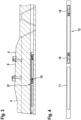
- the concrete sleeper 1 is a side view of a concrete sleeper 1, 2 12 is a view of the concrete sleeper 1 in the longitudinal direction rotated by 90 degrees.
- the concrete sleeper 1 comprises a cuboid base body 2 made of concrete. Sleeper blocks 4 are formed at both ends of the concrete sleeper 1 ; in this area, the concrete sleeper 1 has a raised upper side 5 with a rail support 6 .
- the concrete sleeper 1 is provided for several tie rods 7 .
- a total of six tie rods 7 are provided, the number of tie rods is determined depending on the expected loads and can vary.
- the recess 8 is formed by a hollow profile 9 .
- the hollow profile 9 consists of a steel alloy and has a rectangular cross section.
- the hollow profile 9 is arranged in the base body 2 in such a way that the longer sides of the rectangle are aligned in the vertical direction.
- the hollow profile 9 is cast during the manufacture of the base body 2 of the concrete sleeper 1, as a result of which it is firmly connected to the base body 2.
- the recess 8 formed by the hollow profile 9 is designed as a through opening and thus extends from one end of the concrete sleeper 1 to the opposite end.
- the recess 8 is designed to accommodate a measuring device. Due to the configuration of the hollow profile 9 as a through opening, a measuring device can be inserted into the hollow profile 9 from both ends of the concrete sleeper 1 . The measuring device is only used when required, if no measurement is to be carried out, the recess 8 is empty or hollow. To protect against environmental influences, the recess 8 can be closed with a plug or a cover.
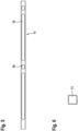
- the measuring device 10 includes a sensor housing 11.
- the sensor housing 11 is designed as a slide-in tube and accommodates the sensor 12 in its interior.
- FIG. 4 is a sectional side view and shows the sensor housing 11 designed as an insertion tube with the sensor 12 arranged therein.
- figure 5 12 is a plan view of the sensor case 11 and 6 12 is a longitudinal view of the sensor case 11.
- FIG. In 6 it can be seen that the sensor housing 11 has a plurality of openings 13 on its upper side. In this exemplary embodiment, two openings 13 extending in the longitudinal direction are provided, in addition there are two smaller openings 14 which have an oval contour.
- the size, position and number of the openings 13, 14 is selected such that the reduction in rigidity caused by the recess 8 in the base body 2 of the concrete sleeper 1 is at least approximately compensated for by the sensor housing 11.
- the square profile of the sensor housing 11 is chosen so that the sensor housing 11 designed as an insertion tube can be inserted into the hollow profile 9, as in FIGS figures 1 and 3 is shown.
- the sensor 12 is designed as a laser sensor.
- the laser sensor includes - as in 4 is shown -, a transmitter 15 and a receiver 16 spaced therefrom. Between the transmitter 15 and the receiver 16 a test section is formed.
- the transmitter 15 emits laser light that impinges on the receiver 16 .
- the transmitter 15 and the receiver 16 are matched to one another in such a way that the laser light hits a specific point on the receiver 16 . In 1 one can see that the sensor 12 is located exactly below a rail support 6 when installed. If the concrete sleeper 1 is run over by a rail vehicle, the vertical force is transmitted via the rail to the rail supports in the base body 2 of the concrete sleeper 1 .
- This vertical force causes bending stress to act on the sensor housing 11 .
- This bending stress occurring between the transmitter 15 and the receiver 16 causes the laser light emitted by the transmitter 15 to occur at a different point on the receiver 16 .
- a measurement signal supplied by the laser sensor is a measure of the bending load. The measurement signal indicates the deviation between the position at which the laser light hits without a load and the position at which the laser light hits when a rail vehicle is loaded. Accordingly, by detecting and evaluating the measurement signal supplied by the sensor 12, conclusions can be drawn about the magnitude and the time profile of a load that occurs.
- the sensor housing 11 In order to obtain an accurate measurement signal, it is necessary for the sensor housing 11 to be coupled to the recess 8 or to the hollow profile 9 forming the recess 8 in a form-fitting and/or force-fitting manner. In this case, the loads generated by the rail vehicle driving over the concrete sleeper 1 are transmitted to the sensor housing 11 and the sensor 12 . It is therefore essential that the sensor housing 11 is firmly accommodated in the concrete sleeper 1 .
- the sensor housing 11 accommodating the sensor 12 is fastened in the recess 8 in a positive and/or non-positive manner by means of a clamping device.
- the clamping device can be inserted into the recess 8 and comprises a first clamping plate 17, which 7 in a side view and in 8 shown in a bottom view. At one end, which forms the outer end of the clamping plate 17 in the assembled state, the clamping plate 17 has an end section 18 which is angled by 90 degrees and is provided with a threaded bore 19 .
- the clamping plate 17 has a ramp profile 20 . Overall, as can be seen in FIGS. 7 and 8, there are two sections provided with the ramp profile 20 .
- a first section is located approximately in the middle of the first clamping plate 17, a second section is located at the inner end of the clamping plate 17.
- the ramp profile comprises one or two ramps 21, which extend from the plate-shaped base body of the clamping plate 17 extend obliquely downwards.
- the direction indication "below” refers to the assembly status.
- the ramp profile having sections are to be understood only as an example.
- a ramp profile can also consist of a different number of individual ramps and the ramps can have a different angle of inclination.
- first clamping plate 17 cooperates with a second clamping plate 22 in the Figures 9 and 10 is shown.
- 9 is a side view and shows the second clamping plate 22 in the assembled state
- Fig. 12 is a plan view of the second clamping plate 22.
- the second clamping plate 22 has a 90 degree angled section 23 at its outer end.
- the angled section 23 has a blind hole 24 .
- the second clamping plate 22 has a ramp profile 25 which is formed in two sections. The positions of the sections having the ramp profile 25 correspond to those of the first clamping plate 17. In 9 the second clamping plate is shown in the installed state, the ramp profile 25 points upwards.
- the ramp profile 25 comprises one or two ramps 26 inclined to the horizontal axis.
- a ramp 26 extends upwards and outwards from the base body 2 of the second clamping plate 22, based on the installed state.
- the direction “outside” refers to an axial end of the concrete sleeper 1.
- the first clamping plate 17 and the second clamping plate 22 together form a clamping device 27.
- the clamping device 27 is shown in the assembled state, ie in the concrete sleeper 1 .
- the clamping device 27 is assembled by placing the first clamping plate 17 and the second clamping plate 22 on top of one another in such a way that the respective ramp profiles 20, 25 are opposite one another.
- the two ramp profiles 20, 25 are designed to be approximately the same as each other. Accordingly, the inclined ramps 21, 26 of the two clamping plates 17, 22 are opposite.
- the clamping device 27 is - as in 3 is shown - positioned on top of the sensor housing 11 and used together with the sensor housing 11 in the hollow profile 9.
- the thickness of the two-part clamping device 27 and the thickness of the sensor housing 11 is adapted to the clear height of the hollow profile 9 so that the clamping device together with the sensor housing 11 can be pushed from the outside into the recess 8 or the hollow profile 9 of the base body 2 of the concrete sleeper 1 can. Then the sensor housing 11 is clamped by means of the clamping device 27 . By turning the screw, its outer end enters the blind hole 24 of the angled section 23 of the second clamping plate 22. By turning the screw, the second clamping plate 22 is displaced relative to the first clamping plate 17 in the longitudinal direction. The second clamping plate 22 is pushed into the interior of the recess 8 .
- the ramp profiles 20, 25 causing the clamping are each located at the point at which the transmitter 15 and the receiver 16 of the laser sensor are also located.
- the measuring device 10 comprising the sensor housing 11 and the sensor 12 is thus positively and/or non-positively connected to the base body 2 of the concrete sleeper 1 by means of the clamping device 27 .
- the screw is turned in the opposite direction, which means that the two clamping plates 17, 22 can be moved in the longitudinal direction again, so that they can be removed from the recess 8 together with the sensor housing 11.
- the concrete sleeper 1 can optionally have a further, third sensor, which is mounted in the middle on the upper side of the concrete sleeper. Such a sensor (not shown) is used to detect a tensile or compressive load.
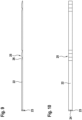
- 11 shows a method for detecting loads and/or deformations acting on a concrete sleeper of a railway track during operation.
- an arrangement with a plurality of concrete sills 1 is shown.
- Each of the concrete sleepers 1 corresponds to the concrete sleeper described above and has force sensors 28 , 29 which are designed to detect support point forces and are arranged on the upper side of the concrete sleeper 1 in an intermediate layer below the rails 30 .
- the force sensors 28, 29 can also be installed later by loosening rail fastenings and positioning the force sensors in an intermediate layer specially designed for this purpose.
- the force sensors 28, 29 detect vertical forces that occur when driving on the railway track. For the sake of simplicity, in 11 only the force sensors are shown for a concrete sleeper.
- the measuring device 10 is inserted into the identified concrete sleeper. The loads and/or deformations acting during operation are then determined by means of the measuring device 10--as described above.
Landscapes
- Engineering & Computer Science (AREA)
- Mechanical Engineering (AREA)
- Architecture (AREA)
- Civil Engineering (AREA)
- Structural Engineering (AREA)
- Investigating Strength Of Materials By Application Of Mechanical Stress (AREA)
- Railway Tracks (AREA)
- Bridges Or Land Bridges (AREA)
- Machines For Laying And Maintaining Railways (AREA)
Description
- Die Erfindung betrifft eine Betonschwelle für einen Eisenbahnfahrweg, mit einem Betonkörper und einer einen Sensor aufweisenden Messeinrichtung zum Erfassen von während des Betriebs auf die Betonschwelle einwirkenden Lasten und/oder Verformungen.
- Für die Auslegung von Betonschwellen existieren Dimensionierungsrichtlinien, die auf Erfahrungswerten beruhen. Darin sind vergleichsweise große Sicherheitsfaktoren berücksichtigt. Die Dimensionierung von Betonschwellen ist allerdings mit gewissen Unsicherheiten behaftet, da die tatsächlichen, im Betrieb auftretenden Belastungen unbekannt sind. Während des Betriebs sind die Betonschwellen sowohl Druckbelastungen als auch Biegebelastungen ausgesetzt. Betonschwellen müssen so dimensioniert werden, dass über die geplante Lebensdauer keine Rissbildung und kein Bruch auftritt.
- In der Vergangenheit sind bereits verschiedene Versuche unternommen worden, um die während des Betriebs auftretenden Lasten zu erfassen.
- In der
DE 40 23 745 A1 wird eine Schwelle vorgeschlagen, die zweiteilig ausgebildet ist und einen trogartigen Grundkörper aufweist, in dem ein Messkolben vertikal beweglich gelagert ist. Die Oberseite des Messkolbens dient als Auflage für eine Schiene. Zwischen dem Grundkörper und dem Messkolben befindet sich im Inneren der Betonschwelle ein Drucksensor. Beim Befahren der Betonschwelle durch ein Schienenfahrzeug können die momentan auftretenden Vertikalkräfte erfasst werden. - In der
EP 2 602 169 A1 wird eine Betonschwelle vorgeschlagen, die fest eingebaute Messeinrichtungen aufweist. Die Messeinrichtungen befinden sich im Inneren der Betonschwelle. - Die
DE 38 44 663 A1 schlägt eine Schwelle für einen Eisenbahnfahrweg vor, die integrierte faseroptische Sensoren aufweist, um Druck- und Biegebeanspruchungen zu erfassen. - In der
DE 10 2010 009 754 A1 wird eine Schwelle vorgeschlagen, die einen lösbar befestigbaren Infrarot-Sensor besitzt. Der Infrarot-Sensor dient zur Überwachung der Temperatur von Schienenfahrzeugkomponenten. - Die herkömmlichen Betonschwellen mit fest eingebauten Messaufnehmern ermöglichen eine zuverlässige Erfassung der während des Betriebs auftretenden Belastungen. Allerdings sind derartige, mit Messeinrichtungen ausgerüstete Betonschwellen vergleichsweise teuer, weshalb in der Praxis nur eine geringe Anzahl von Betonschwellen damit ausgerüstet werden kann.
- Der Erfindung liegt die Aufgabe zugrunde, eine Betonschwelle anzugeben, mit der die Erfassung von während des Betriebs auftretenden Lasten einfacher und flexibler durchgeführt werden kann.
- Zur Lösung dieser Aufgabe ist bei einer Betonschwelle der eingangs genannten Art erfindungsgemäß vorgesehen, dass sie wenigstens eine durch ein fest und integral mit dem Betonkörper der Betonschwelle verbundenes Hohlprofil gebildete Ausnehmung aufweist, in der die Messeinrichtung entnehmbar einsetzbar oder eingesetzt ist, wobei das Hohlprofil eine exakte Anlagefläche für die Messeinrichtung bildet und auf die Betonschwelle einwirkende Lasten unmittelbar über das Hohlprofil auf die Messeinrichtung übertragbar sind.
- Im Gegensatz zu den beschriebenen herkömmlichen Betonschwellen, bei denen die Messeinrichtung fest eingebaut, insbesondere im Inneren vergossen ist, ermöglicht die erfindungsgemäße Betonschwelle das bedarfsweise Einbringen der Messeinrichtung, wenn tatsächlich eine Messung durchgeführt werden soll. Sofern keine Messung durchzuführen ist, kann die Betonschwelle wie eine herkömmliche Betonschwelle, die keine Messeinrichtung aufweist, benutzt werden. Auf diese Weise können entlang eines Schienenfahrwegs beliebig viele erfindungsgemäße Betonschwellen eingebaut werden, die für die Aufnahme einer Messeinrichtung vorbereitet und geeignet sind. Bei Bedarf werden dann ein oder mehrere erfindungsgemäße Betonschwellen mit der Messeinrichtung versehen. Dazu wird die Messeinrichtung in die jeweilige Aufnahme der Betonschwelle eingesetzt. Auf diese Weise können unterschiedliche Abschnitte der Schienenfahrbahn untersucht werden. Durch die Erfindung ergibt sich der Vorteil, dass lediglich eine einzige Messeinrichtung oder gegebenenfalls mehrere Messeinrichtungen erforderlich sind, die nicht dauerhaft installiert werden und zur Durchführung einer Messung an einer gewünschten Position installiert werden. Da die Messeinrichtung bzw. die mehreren Messeinrichtungen jedoch exakt an einer bestimmten Stelle des Schienenfahrwerks eingebaut werden können, um eine Messung durchzuführen, ist eine effiziente Nutzung möglich. Im Gegensatz dazu ermöglichen die erwähnten herkömmlichen Betonschwellen jeweils nur eine Messung an dem Einbauort der entsprechenden Betonschwelle. Daraus ergibt sich der Vorteil, dass die Erfassung von während des Betriebs auftretenden Lasten einfach, flexibel, zielgerichtet und kostengünstig durchgeführt werden kann.
- Bei der erfindungsgemäßen Betonschwelle ist die Ausnehmung durch ein Hohlprofil gebildet, das integral mit dem Beton verbunden ist. das Hohlprofil kann beispielsweise ein Metallprofil sein, insbesondere ein Stahlprofil oder ein Aluminiumprofil. Das Hohlprofil bildet eine exakte Anlagefläche für die Messeinrichtung, sodass Messungen genau und reproduzierbar durchgeführt werden können. Das Hohlprofil ist fest mit dem Betonkörper der Betonschwelle verbunden, sodass auf die Betonschwelle einwirkende Lasten unmittelbar über das Hohlprofil auf die Messeinrichtung übertragen werden. Ein als Metallprofil ausgebildetes Hohlprofil weist einen höheren Elastizitätsmodul als der ihn umgebende Beton auf. Durch das Hohlprofil wird die durch die Ausnehmung in dem Betonkörper hervorgerufene Verringerung der Steifigkeit näherungsweise kompensiert. Das Hohlprofil ist so ausgelegt, dass sich die erfindungsgemäße Betonschwelle näherungsweise wie eine herkömmliche, keine Ausnehmung aufweisende Betonschwelle verhält. Die Durchführung einer Messung mittels der erfindungsgemäßen Betonschwelle ermöglicht somit eine realistische Erfassung der auf herkömmliche Betonschwellen einwirkenden Belastungen während des Betriebs der Schienenfahrbahn.
- Eine Weiterbildung der Erfindung sieht vor, dass das Hohlprofil der erfindungsgemäßen Betonschwelle einen rechteckigen oder quadratischen oder runden Querschnitt aufweist. Derartige Hohlprofile sind kommerziell erhältlich. Vorzugsweise ist der Querschnitt rechteckig oder quadratisch. Ein rechteckiger oder quadratischer Querschnitt weist eine obere und eine untere Innenfläche auf, die einander gegenüberliegen. Diese Flächen können benutzt werden, um die Messeinrichtung exakt an einer gewünschten Position so anzuordnen, dass die auftretenden Lasten von der Betonschwelle über das Hohlprofil auf die Messeinrichtung übertragen werden.
- Es liegt auch im Rahmen der Erfindung, dass der Sensor der Messeinrichtung in einem Sensorgehäuse aufgenommen ist, das in die Ausnehmung einsetzbar oder eingesetzt ist. Der Sensor der Messeinrichtung kann somit entweder direkt in das Hohlprofil eingesetzt werden, alternativ kann der Sensor in einem Sensorgehäuse aufgenommen sein. Das Sensorgehäuse schützt die Messeinrichtung vor Umwelteinflüssen und gewährleistet eine hohe Qualität der erfassten Messdaten. Das Sensorgehäuse ist allerdings optional. Sofern die Messeinrichtung ohne Sensorgehäuse benutzt wird, kann die Ausnehmung, insbesondere das Hohlprofil am freien Ende verschlossen werden, beispielsweise durch einen Stopfen, eine Klappe, einen Deckel oder dergleichen.
- In diesem Zusammenhang kann es vorgesehen sein, dass der Sensor mittels einer Klemmvorrichtung formschlüssig und/oder kraftschlüssig in der Ausnehmung befestigbar oder befestigt ist. Sofern ein Sensorgehäuse vorgesehen ist, in dem der Sensor aufgenommen ist, kann es alternativ vorgesehen sein, dass das Sensorgehäuse mittels einer Klemmvorrichtung formschlüssig und/oder kraftschlüssig in der Ausnehmung befestigbar oder befestigt ist. Sofern die Ausnehmung durch ein Hohlprofil gebildet ist, wird der Sensor bzw. das Sensorgehäuse mittels der Klemmvorrichtung in dem Hohlprofil formschlüssig und/oder kraftschlüssig befestigt. Durch die formschlüssige bzw. kraftschlüssige Befestigung wird sichergestellt, dass die im Betrieb auftretenden Lasten, insbesondere Vertikalkräfte, auf die Messeinrichtung übertragen werden, sodass eine genaue messtechnische Erfassung der Lasten möglich ist. Die kraftschlüssige Befestigung kann auch durch einen Magneten erfolgen.
- Eine bevorzugte Variante der erfindungsgemäßen Betonschwelle sieht vor, dass die Klemmvorrichtung in die Ausnehmung einsetzbar ist und sich einerseits an einer Innenfläche der Ausnehmung und andererseits an einer Außenfläche des Sensorgehäuses abstützt. Die Klemmvorrichtung kann somit in die Ausnehmung, gegebenenfalls in das Hohlprofil, eingesetzt und dort verspannt werden.
- Gemäß einer weiteren Ausgestaltung der erfindungsgemäßen Betonschwelle kann die Klemmvorrichtung eine erste Klemmplatte aufweisen, die mit einer zweiten Klemmplatte derart zusammenwirkt, dass durch eine Längsverschiebung der beiden aufeinander liegenden Klemmplatten relativ zueinander deren Gesamtdicke einstellbar ist. Die erste und/oder die zweite Klemmplatte ist dazu so geformt, dass sich bei einer Längsverschiebung der beiden Klemmplatten die gewünschte Dickenänderung ergibt. Vorzugsweise umfasst die Betonschwelle die erste Klemmplatte und die zweite Klemmplatte. Optional kann eine der Klemmplatten fest mit der Messeinrichtung verbunden sein. Eine der Klemmplatten kann somit auch als eine Außenseite der Messeinrichtung ausgebildet sein. Bei dieser Variante ist eine Klemmplatte einstückig mit der Messeinrichtung verbunden.
- Gemäß einer weiteren Ausgestaltung der erfindungsgemäßen Betonschwelle kann die erste Klemmplatte eine Gewindebohrung aufweisen und die zweite Klemmplatte kann mittels einer die Gewindebohrung durchsetzenden Schraube längsverschiebbar sein. Somit kann durch Drehen der Schraube die erforderliche Längsverschiebung einer Klemmplatte bewirkt werden, wodurch die andere Klemmplatte verschoben wird, damit sich die Gesamtdicke der beiden Klemmplatten ändert. Durch Vergrößern der Gesamtdicke können die beiden Klemmplatten in der Ausnehmung, insbesondere in dem Hohlprofil, verklemmt werden. Eine der Klemmplatten stützt sich dabei an einer Innenseite der Ausnehmung, insbesondere an der Innenseite des Hohlprofils ab. Die andere Klemmplatte stützt sich an der Messeinrichtung, gegebenenfalls an einem Sensorgehäuse ab. Eine gegenüberliegende Seite der Messeinrichtung, gegebenenfalls des Sensorgehäuses, stützt sich an einer gegenüberliegenden Seite der Ausnehmung, insbesondere des Hohlprofils, ab.
- Mit besonderem Vorteil kann es bei der erfindungsgemäßen Betonschwelle vorgesehen sein, dass die Klemmplatten jeweils ein Rampenprofil aufweisen, wobei die beiden Rampenprofile zumindest näherungsweise gegengleich zueinander ausgebildet sind. Ein Rampenprofil weist eine oder mehrere schräge Flächen auf. Die Klemmplatten können auch ein Sägezahnprofil mit mehreren schrägen Flächen aufweisen. Im einfachsten Fall könnten die beiden Klemmplatten auch als Keilprofile ausgebildet sein, sodass bei einer Relativverschiebung zueinander in Längsrichtung die benötigte Änderung der Gesamtdicke bewirkt wird, wodurch die Klemmung erzielt wird.
- Sofern der Sensor der Messeinrichtung in einem Sensorgehäuse aufgenommen ist, kann das Sensorgehäuse vorzugsweise als Rohr ausgebildet sein. Das Rohr kann vorzugsweise einen runden oder einen eckigen Querschnitt aufweisen.
- Eine Variante der erfindungsgemäßen Betonschwelle sieht vor, dass die Ausnehmung als Durchgangsöffnung ausgebildet ist. Die Durchgangsöffnung kann von dem Hohlprofil durchsetzt sein. Die Durchgangsöffnung erstreckt sich vorzugsweise in Längsrichtung der Betonschwelle. In der Durchgangsöffnung kann ein Anschlag für die Messeinrichtung, gegebenenfalls auch zwei Anschläge, vorhanden sein. Auf diese Weise ist es einfach möglich, die Messeinrichtung exakt an einer bestimmten Position in Längsrichtung in die Ausnehmung einzusetzen und dort mittels der Klemmvorrichtung zu arretieren. Wenn die Ausnehmung als Durchgangsöffnung ausgebildet ist, kann eine erste Messeinrichtung ausgehend von einem Ende und eine zweite Messeinrichtung von dem gegenüberliegenden Ende ausgehend eingesetzt werden.
- Gemäß einer weiteren Ausgestaltung der erfindungsgemäßen Betonschwelle kann sie zwei oder mehr Ausnehmungen aufweisen, die sich vorzugsweise in Längsrichtung von beiden Enden nach innen erstrecken. Insbesondere können die Ausnehmungen so positioniert sein, dass die Messeinrichtungen unterhalb der Schienenauflagen der Betonschwelle positionierbar sind. Alternativ kann eine Messeinrichtung in der Schwellenmitte, vorzugsweise in der Nähe der Oberseite der Schwelle, angeordnet sein.
- Bei der erfindungsgemäßen Betonschwelle kann es vorgesehen sein, dass der Sensor als Lasersensor ausgebildet ist, der einen Laserlicht emittierenden Sender und einen Empfänger aufweist, die voneinander beabstandet angeordnet sind, wobei der Lasersensor dazu ausgebildet ist, eine durch eine auf die Betonschwelle einwirkende Last und/oder eine Verformung zu erfassen. Der Lasersensor umfasst eine Messtrecke, die zwischen dem Sensor und dem Empfänger gebildet ist. Der Sender und der Empfänger sind aufeinander ausgerichtet, sodass das Laserlicht auf eine bestimmte Position des Empfängers auftrifft. Sofern der Sensor eine Belastung, insbesondere ein Vertikalkraft, erfährt, bewirkt diese Kraft, dass auf die Messeinrichtung eine Biegebelastung ausgeübt wird und das Laserlicht an einer anderen Position auf den Empfänger auftrifft. Diese Abweichung wird von dem Sensor erfasst. Die Abweichung ist abhängig von der auf die Betonschwelle einwirkenden Last. Dementsprechend kann durch die Auswertung des Sensorsignals die auftretende Last erfasst und charakterisiert werden.
- Bei der erfindungsgemäßen Betonschwelle wird es bevorzugt, dass die Messeinrichtung so in der Ausnehmung positioniert ist, dass sich der Sensor zumindest näherungsweise unterhalb einer Schienenauflagefläche oder im Bereich der Schwellenmitte befindet. Gegebenenfalls können sich unter beiden Schienenauflageflächen entsprechende Sensoren befinden.
- Gemäß einer Weiterbildung der erfindungsgemäßen Betonschwelle kann es vorgesehen sein, dass sie einen weiteren Sensor aufweist, der an der Oberfläche oder zumindest in der Nähe der Oberfläche der Betonschwelle, in deren mittleren Bereich, angeordnet ist. Bei diesem Sensor kann es sich um einen Kraftsensor oder um einen Sensor zum Erfassen einer Zug- oder Druckbelastung handeln.
- Daneben betrifft die Erfindung ein Verfahren zum Erfassen von während des Betriebs auf einer Betonschwelle für einen Eisenbahnfahrweg einwirkenden Lasten und/oder Verformungen.
- Das erfindungsgemäße Verfahren zeichnet sich dadurch aus, dass eine eine Ausnehmung für eine Messeinrichtung ausweisende Betonschwelle der beschriebenen Art verwendet wird, und die Messeinrichtung entnehmbar in der Ausnehmung eingesetzt ist.
- Gemäß einer Weiterbildung des erfindungsgemäßen Verfahrens können vorab die folgenden Schritte durchgeführt werden: Positionieren wenigstens eines Kraftsensors bei mehreren Betonschwellen zum Erfassen von Stützpunktkräften, Feststellen, welche Betonschwelle die maßgebende, insbesondere die größte, Belastung erfährt, und Einsetzen der Messeinrichtung in diejenige Betonschwelle mit der größten Belastung.
- In der Praxis hat es sich herausgestellt, dass mehrere Betonschwellen, die nah beieinander, beispielsweise benachbart zueinander, angeordnet sind, unterschiedliche Belastungen erfahren. Ein Grund dafür liegt in der unterschiedlichen Bettung der einzelnen Betonschwellen bei einem Schotterunterbau. Mittels des erfindungsgemäßen Verfahrens ist es möglich, diejenige Betonschwelle zu identifizieren, die die maßgebende, insbesondere die größte, Belastung erfährt. Anschließend wird die Messeinrichtung in diejenige Betonschwelle eingesetzt, bei der die größte Belastung auftritt. Durch das erfindungsgemäße Verfahren kann somit festgestellt werden, an welcher Position innerhalb eines bestimmten Abschnitts einer Schienenfahrbahn die Messung am zweckmäßigsten vorgenommen werden kann.
- Weitere Vorteile und Einzelheiten der Erfindung werden nachfolgend anhand von Ausführungsbeispielen unter Bezugnahme auf die Zeichnungen erläutert. Die Zeichnungen sind schematische Darstellungen und zeigen:
- Fig. 1
- eine geschnittene Seitenansicht einer erfindungsgemäßen Betonschwelle,
- Fig. 2
- eine dem gegenüber um 90 Grad gedrehte Ansicht in Längsrichtung,
- Fig. 3
- eine vergrößerte Ansicht der linken Hälfte von
Fig. 1 , - Fig. 4
- eine geschnittene Seitenansicht eines Sensorgehäuses,
- Fig. 5
- eine Draufsicht des in
Fig. 4 gezeigten Sensorgehäuses, - Fig. 6
- eine Ansicht des Profils des Sensorgehäuses,
- Fig. 7
- eine Seitenansicht einer ersten Klemmplatte,
- Fig. 8
- die in
Fig. 7 gezeigte Klemmplatte in einer Ansicht von unten, - Fig. 9
- eine Seitenansicht einer zweiten Klemmplatte,
- Fig. 10
- eine Draufsicht der in
Fig. 9 gezeigten zweiten Klemmplatte, und - Fig. 11
- ein Ausführungsbeispiel eines erfindungsgemäßen Verfahrens.
-
Fig. 1 ist eine Seitenansicht einer Betonschwelle 1,Fig. 2 ist eine demgegenüber um 90 Grad gedrehte Ansicht der Betonschwelle 1 in Längsrichtung. Die Betonschwelle 1 umfasst einen quaderförmigen Grundkörper 2 aus Beton. An beiden Enden der Betonschwelle 1 sind Schwellenblöcke 4 ausgebildet, in diesem Bereich weist die Betonschwelle 1 eine erhöhte Oberseite 5 mit einer Schienenauflage 6 auf. - In
Fig. 2 erkennt man, dass die Betonschwelle 1 für mehrere Spannstäbe 7 vorgesehen ist. In dem dargestellten Ausführungsbeispiel sind insgesamt sechs Spannstäbe 7 vorgesehen, die Anzahl der Spannstäbe wird in Abhängigkeit der zu erwartenden Lasten festgelegt und kann variieren. - Im unteren Teil des Grundkörpers 2 der Betonschwelle 1 befindet sich eine Ausnehmung 8. In diesem Ausführungsbeispiel wird die Ausnehmung 8 durch ein Hohlprofil 9 gebildet. Das Hohlprofil 9 besteht aus einer Stahllegierung und besitzt einen Rechteckquerschnitt. Das Hohlprofil 9 ist so in dem Grundkörper 2 angeordnet, dass die längeren Rechteckseiten in Vertikalrichtung ausgerichtet sind. Das Hohlprofil 9 wird bei der Herstellung des Grundkörpers 2 der Betonschwelle 1 vergossen, wodurch es fest mit dem Grundkörper 2 verbunden ist.
- In der Seitenansicht von
Fig. 1 erkennt man, dass die durch das Hohlprofil 9 gebildete Ausnehmung 8 als Durchgangsöffnung ausgebildet ist und sich somit von einem Ende der Betonschwelle 1 bis zum entgegengesetzten Ende erstreckt. - Die Ausnehmung 8 ist dazu ausgebildet, eine Messeinrichtung aufzunehmen. Durch die Ausgestaltung des Hohlprofils 9 als Durchgangsöffnung kann von beiden Enden der Betonschwelle 1 eine Messeinrichtung in das Hohlprofil 9 eingesetzt werden. Die Messeinrichtung wird nur bei Bedarf eingesetzt, sofern keine Messung vorgenommen werden soll, ist die Ausnehmung 8 leer bzw. hohl. Zum Schutz vor Umwelteinflüssen kann die Ausnehmung 8 mit einem Stopfen oder einem Deckel verschlossen werden.
- In
Fig. 1 ist dargestellt, dass in die Ausnehmung 8 zwei Messeinrichtungen eingesetzt sind. Unterhalb jeder Schienenauflage 6 befindet sich jeweils eine Messeinrichtung. - Nachfolgend wird auf
Fig. 3 Bezug genommen, die eine vergrößerte Ansicht der linken Hälfte vonFig. 1 zeigt. Die Messeinrichtung 10 umfasst ein Sensorgehäuse 11. Das Sensorgehäuse 11 ist als Einschubrohr ausgebildet und nimmt den Sensor 12 in seinem Inneren auf. -
Fig. 4 ist eine geschnittene Seitenansicht und zeigt das als Einschubrohr ausgebildete Sensorgehäuse 11 mit dem darin angeordneten Sensor 12. -
Fig. 5 ist eine Draufsicht des Sensorgehäuses 11 undFig. 6 ist eine Ansicht des Sensorgehäuses 11 in Längsrichtung. InFig. 6 erkennt man, dass das Sensorgehäuse 11 an seiner Oberseite mehrere Öffnungen 13 aufweist. In diesem Ausführungsbeispiel sind zwei sich in Längsrichtung erstreckende Öffnungen 13 vorgesehen, zusätzlich sind zwei kleinere Öffnungen 14 vorhanden, die eine ovale Kontur aufweisen. - Die Größe, Position und Anzahl der Öffnungen 13, 14 ist so gewählt, dass die durch die Ausnehmung 8 in dem Grundkörper 2 der Betonschwelle 1 verursachte Verringerung der Steifigkeit durch das Sensorgehäuse 11 zumindest näherungsweise ausgeglichen wird.
- Das quadratische Profil des Sensorgehäuses 11 ist so gewählt, dass das als Einschubrohr ausgebildete Sensorgehäuse 11 in das Hohlprofil 9 einsetzbar ist, wie in den
Figuren 1 und3 gezeigt ist. - In diesem Ausführungsbeispiel ist der Sensor 12 als Lasersensor ausgebildet. Der Lasersensor umfasst - wie in
Fig. 4 gezeigt ist -, einen Sender 15 und einen davon beabstandeten Empfänger 16. Zwischen dem Sender 15 und dem Empfänger 16 ist eine Messtrecke gebildet. Der Sender 15 sendet Laserlicht aus, das auf den Empfänger 16 auftrifft. Der Sender 15 und der Empfänger 16 sind so aufeinander abgestimmt, dass das Laserlicht auf eine bestimmte Stelle des Empfängers 16 auftrifft. InFig. 1 erkennt man, dass sich der Sensor 12 im eingebauten Zustand exakt unterhalb einer Schienenauflage 6 befindet. Wenn die Betonschwelle 1 von einem Schienenfahrzeug überfahren wird, wird die Vertikalkraft über die Schiene auf die Schienenauflagen in den Grundkörper 2 der Betonschwelle 1 übertragen. - Diese Vertikalkraft verursacht eine auf das Sensorgehäuse 11 wirkende Biegebelastung. Diese zwischen dem Sender 15 und dem Empfänger 16 auftretende Biegebelastung führt dazu, dass das von dem Sender 15 ausgesendete Laserlicht an einer anderen Stelle auf dem Empfänger 16 auftritt. Ein von dem Lasersensor geliefertes Messsignal ist ein Maß für die Biegebelastung. Das Messsignal gibt die Abweichung zwischen der Position, auf die das Laserlicht ohne Belastung auftritt und der Position, an der das Laserlicht bei einer Belastung durch ein Schienenfahrzeug auftrifft an. Dementsprechend kann durch die Erfassung und Auswertung des von dem Sensor 12 gelieferten Messsignals auf die Größe und den zeitlichen Verlauf einer auftretenden Belastung geschlossen werden.
- Um ein genaues Messsignal zu erhalten, ist es erforderlich, dass das Sensorgehäuse 11 formschlüssig und/oder kraftschlüssig mit der Ausnehmung 8 bzw. dem die Ausnehmung 8 bildenden Hohlprofil 9 gekoppelt ist. In diesem Fall werden die durch das die Betonschwelle 1 überfahrende Schienenfahrzeug erzeugten Lasten auf das Sensorgehäuse 11 und den Sensor 12 übertragen. Wesentlich ist somit, dass das Sensorgehäuse 11 fest in der Betonschwelle 1 aufgenommen ist.
- Das den Sensor 12 aufnehmende Sensorgehäuse 11 ist mittels einer Klemmvorrichtung formschlüssig und/oder kraftschlüssig in der Ausnehmung 8 befestigt. Die Klemmvorrichtung ist in die Ausnehmung 8 einsetzbar und umfasst eine erste Klemmplatte 17, die in
Fig. 7 in einer Seitenansicht und inFig. 8 in einer Ansicht von unten dargestellt ist. An einem Ende, das im montierten Zustand das äußere Ende der Klemmplatte 17 bildet, weist die Klemmplatte 17 einen um 90 Grad abgewinkelten Endabschnitt 18 auf, der mit einer Gewindebohrung 19 versehen ist. Die Klemmplatte 17 weist ein Rampenprofil 20 auf. Insgesamt sind - wie in den Figuren 7 und 8 zu sehen ist - zwei mit dem Rampenprofil 20 versehene Abschnitte vorhanden. Ein erster Abschnitt befindet sich näherungsweise in der Mitte der ersten Klemmplatte 17, ein zweiter Abschnitt befindet sich an dem inneren Ende der Klemmplatte 17. Das Rampenprofil umfasst in diesem Ausführungsbeispiel eine bzw. zwei Rampen 21, die sich ausgehend von dem plattenförmigen Grundkörper der Klemmplatte 17 schräg nach unten erstrecken. Die Richtungsangabe "unten" bezieht sich dabei auf den Montagezustand. Die in denFiguren 7 und 8 gezeigten, das Rampenprofil aufweisenden Abschnitte sind lediglich beispielhaft zu verstehen. Ein Rampenprofil kann alternativ auch aus einer anderen Anzahl von einzelnen Rampen bestehen und die Rampen können einen anderen Neigungswinkel besitzen. Wesentlich ist jedoch, dass sich die Rampe 21 ausgehend von dem Grundkörper der Klemmplatte 17 nach unten und nach innen erstreckt. - Die in den
Figuren 7 und 8 gezeigte erste Klemmplatte 17 wirkt mit einer zweiten Klemmplatte 22 zusammen, die in denFiguren 9 und 10 gezeigt ist.Fig. 9 ist eine Seitenansicht und zeigt die zweite Klemmplatte 22 im montierten Zustand,Fig. 10 ist eine Draufsicht auf die zweite Klemmplatte 22. - Die zweite Klemmplatte 22 weist an ihrem äußeren Ende einen um 90 Grad abgewinkelten Abschnitt 23 auf. Der abgewinkelte Abschnitt 23 weist ein Sackloch 24 auf. Die zweite Klemmplatte 22 weist ein Rampenprofil 25 auf, das an zwei Abschnitten ausgebildet ist. Die Positionen der das Rampenprofil 25 aufweisenden Abschnitte entsprechen denjenigen der ersten Klemmplatte 17. In
Fig. 9 ist die zweite Klemmplatte im Einbauzustand dargestellt, das Rampenprofil 25 weist nach oben. Das Rampenprofil 25 umfasst eine oder zwei zur horizontalen Achse geneigten Rampen 26. Eine Rampe 26 erstreckt sich von dem Grundkörper 2 der zweiten Klemmplatte 22 nach oben und nach außen, bezogen auf den Einbauzustand. Die Richtungsangabe "außen" bezeichnet dabei ein axiales Ende der Betonschwelle 1. - Die erste Klemmplatte 17 und die zweite Klemmplatte 22 bilden gemeinsam eine Klemmvorrichtung 27. In
Fig. 3 ist die Klemmvorrichtung 27 im montierten Zustand, d. h. in der Betonschwelle 1, dargestellt. Die Klemmvorrichtung 27 wird montiert, indem die erste Klemmplatte 17 und die zweite Klemmplatte 22 so aufeinander gelegt werden, dass sich die jeweiligen Rampenprofile 20, 25 gegenüberliegen. Die beiden Rampenprofile 20, 25 sind näherungsweise gegengleich zueinander ausgebildet. Demnach liegen sich die schrägen Rampen 21, 26 der beiden Klemmplatten 17, 22 jeweils gegenüber. Die Klemmvorrichtung 27 wird - wie inFig. 3 gezeigt ist - auf der Oberseite des Sensorgehäuses 11 positioniert und gemeinsam mit dem Sensorgehäuse 11 in das Hohlprofil 9 eingesetzt. Die Dicke der zweiteiligen Klemmvorrichtung 27 und die Dicke des Sensorgehäuses 11 ist so an die lichte Höhe des Hohlprofils 9 angepasst, dass die Klemmvorrichtung gemeinsam mit dem Sensorgehäuse 11 von außen in die Ausnehmung 8 bzw. das Hohlprofil 9 des Grundkörpers 2 der Betonschwelle 1 eingeschoben werden kann. Anschließend erfolgt die Klemmung des Sensorgehäuses 11 mittels der Klemmvorrichtung 27. Dazu wird eine Schraube in die Gewindebohrung 19 des abgewinkelten Abschnitts 18 der ersten Klemmplatte 17 geschraubt. Durch Drehen der Schraube gelangt deren äußeres Ende in das Sackloch 24 des abgewinkelten Abschnitts 23 der zweiten Klemmplatte 22. Durch Drehen der Schraube wird die zweite Klemmplatte 22 relativ zur ersten Klemmplatte 17 in Längsrichtung verschoben. Die zweite Klemmplatte 22 wird in das Innere der Ausnehmung 8 verschoben. Die einander gegenüberliegenden und einander berührenden Rampen 21, 26 der beiden Klemmplatten 17, 22 gleiten aufeinander, wodurch sich deren Gesamtdicke erhöht. Die Schraube wird solange gedreht, bis die Oberseite der ersten Klemmplatte 17 die obere Innenfläche des Hohlprofils 9 berührt. Auf diese Weise klemmt die Klemmvorrichtung 27 das Sensorgehäuse in dem Hohlprofil 9 fest. - In
Fig. 3 ist erkennbar, dass sich die die Klemmung bewirkenden Rampenprofile 20, 25 jeweils an der Stelle befinden, an der sich auch der Sender 15 und der Empfänger 16 des Lasersensors befinden. Mittels der Klemmvorrichtung 27 wird somit die das Sensorgehäuse 11 und den Sensor 12 umfassende Messeinrichtung 10 formschlüssig und/oder kraftschlüssig mit dem Grundkörper 2 der Betonschwelle 1 verbunden. Um die Messeinrichtung 10 nach der Durchführung einer Messung wieder zu entnehmen, wird die Schraube in die umgekehrte Richtung gedreht, dadurch sind die beiden Klemmplatten 17, 22 wieder in Längsrichtung verschiebbar, sodass sie gemeinsam mit dem Sensorgehäuse 11 aus der Ausnehmung 8 entfernt werden können. - Die Betonschwelle 1 kann optional einen weiteren, dritten Sensor aufweisen, der auf der Oberseite der Betonschwelle, in der Mitte angebracht ist. Ein derartiger (nicht gezeigter) Sensor dient zum Erfassen einer Zug- oder Druckbelastung.
-
Fig. 11 zeigt ein Verfahren zum Erfassen von während des Betriebs auf eine Betonschwelle eines Eisenbahnfahrwegs einwirkenden Lasten und/oder Verformungen. InFig. 11 ist eine Anordnung mit einer Mehrzahl von Betonschweller 1 dargestellt. Jede der Betonschwellen 1 entspricht der zuvor beschriebenen Betonschwelle und weist Kraftsensoren 28, 29 auf die zum Erfassen von Stützpunktkräften ausgebildet sind und an der Oberseite der Betonschwelle 1 in einer Zwischenlage unterhalb der Schienen 30 angeordnet sind. Durch Lösen von Schienenbefestigungen und Positionieren der Kraftsensoren in eine speziell dafür ausgebildete Zwischenlage können die Kraftsensoren 28, 29 auch nachträglich installiert werden. Die Kraftsensoren 28, 29 erfassen Vertikalkräfte, die beim Befahren des Eisenbahnfahrwegs auftreten. Der Einfachheit halber sind inFig. 11 lediglich bei einer Betonschwelle die Kraftsensoren dargestellt. In dem mehrere benachbarte oder in einem bestimmten Bereich verlegte Betonschwellen mit den Kraftsensoren versehen werden, kann festgestellt werden, welche Betonschwelle die größte Belastung erfährt. Unterschiede können sich beispielsweise durch den Zustand des Unterbaus ergeben, insbesondere bei Schotterstrecken. Nachdem festgestellt worden ist, welche der mehreren Betonschwellen 1 die größte Belastung erfährt, wird in die identifizierte Betonschwelle die Messeinrichtung 10 eingesetzt. Anschließend werden mittels der Messeinrichtung 10 - wie zuvor beschrieben - die während des Betriebs einwirkenden Lasten und/oder Verformungen ermittelt. -
- 1
- Betonschwelle
- 2
- Grundkörper
- 4
- Schwellenblock
- 5
- Oberseite
- 6
- Schienenauflage
- 7
- Spannstab
- 8
- Ausnehmung
- 9
- Hohlprofil
- 10
- Messeinrichtung
- 11
- Sensorgehäuse
- 12
- Sensor
- 13
- Öffnung
- 14
- Öffnung
- 15
- Sender
- 16
- Empfänger
- 17
- Klemmplatte
- 18
- Abschnitt
- 19
- Gewindebohrung
- 20
- Rampenprofil
- 21
- Rampe
- 22
- Klemmplatte
- 23
- Abschnitt
- 24
- Sackloch
- 25
- Rampenprofil
- 26
- Rampen
- 27
- Klemmvorrichtung
- 28
- Sensor
- 29
- Auswerteeinrichtung
Claims (17)
- Betonschwelle (1) für einen Eisenbahnfahrweg, mit einem Betonkörper und einer einen Sensor (12) aufweisenden Messeinrichtung (10) zum Erfassen von während des Betriebs auf die Betonschwelle (1) einwirkenden Lasten und/oder Verformungen, dadurch gekennzeichnet, dass die Betonschwelle (1) wenigstens eine durch ein fest und integral mit dem Betonkörper der Betonschwelle (1) verbundenes Hohlprofil (9) gebildete Ausnehmung (8) aufweist, in die die Messeinrichtung (10) entnehmbar einsetzbar oder eingesetzt ist, wobei das Hohlprofil (9) eine exakte Anlagefläche für die Messeinrichtung (10) bildet und auf die Betonschwelle (1) einwirkende Lasten unmittelbar über das Hohlprofil (9) auf die Messeinrichtung (10) übertragbar sind.
- Betonschwelle (1) nach Anspruch 1, dadurch gekennzeichnet, dass sich das Hohlprofil (9) in Längsrichtung des Betonkörpers erstreckt.
- Betonschwelle (1) nach Anspruch 2, dadurch gekennzeichnet, dass das Hohlprofil (9) einen rechteckigen oder quadratischen oder runden Querschnitt aufweist.
- Betonschwelle (1) nach einem der vorangehenden Ansprüche, dadurch gekennzeichnet, dass der Sensor (12) der Messeinrichtung (10) in einem Sensorgehäuse (11) aufgenommen ist, das in die Ausnehmung (8) einsetzbar oder eingesetzt ist.
- Betonschwelle (1) nach einem der vorangehenden Ansprüche, dadurch gekennzeichnet, dass der Sensor (12), gegebenenfalls das Sensorgehäuse (11), mittels einer Klemmvorrichtung (27) formschlüssig und/oder kraftschlüssig in der Ausnehmung (8) befestigbar oder befestigt ist.
- Betonschwelle (1) nach Anspruch 5, dadurch gekennzeichnet, dass die Klemmvorrichtung (27) in die Ausnehmung (8) einsetzbar ist und sich einerseits an einer Innenfläche der Ausnehmung (8) und andererseits an einer Außenfläche des Sensorgehäuses (11) abstützt.
- Betonschwelle (1) nach Anspruch 5 oder 6, dadurch gekennzeichnet, dass die Klemmvorrichtung (28) eine erste Klemmplatte (17) aufweist, die mit einer zweiten Klemmplatte (22) derart zusammenwirkt, dass durch eine Längsverschiebung der beiden aufeinander liegenden Klemmplatten (17, 22) relativ zueinander deren Gesamtdicke einstellbar ist.
- Betonschwelle (1) nach Anspruch 7, dadurch gekennzeichnet, dass die erste Klemmplatte (17) eine Gewindebohrung (19) aufweist und die zweite Klemmplatte (22) mittels einer die Gewindebohrung (19) durchsetzenden Schraube längsverschiebbar ist.
- Betonschwelle (1) nach Anspruch 7 oder 8, dadurch gekennzeichnet, dass die Klemmplatten (17, 22) jeweils ein Rampenprofil (25) oder ein Sägezahnprofil aufweisen, wobei die beiden Rampenprofile (25) vorzugsweise zumindest näherungsweise gegengleich zueinander ausgebildet sind.
- Betonschwelle (1) nach einem der Ansprüche 4 bis 9, dadurch gekennzeichnet, dass das Sensorgehäuse (11) als Rohr ausgebildet ist und vorzugsweise einen runden oder eckigen Querschnitt aufweist.
- Betonschwelle (1) nach einem der vorangehenden Ansprüche, dadurch gekennzeichnet, dass die Ausnehmung (8) als Durchgangsöffnung ausgebildet ist.
- Betonschwelle (1) nach einem der vorangehenden Ansprüche, dadurch gekennzeichnet, dass sie zwei oder mehr Ausnehmungen (8) aufweist, die sich vorzugsweise in Längsrichtung von beiden Enden nach innen erstrecken.
- Betonschwelle (1) nach einem der vorangehenden Ansprüche, dadurch gekennzeichnet, dass der Sensor (12) als Lasersensor ausgebildet ist, der einen Laserlicht emittierenden Sender (15) und einen Empfänger (16) aufweist, die voneinander beabstandet angeordnet sind, wobei der Lasersensor dazu ausgebildet ist, eine durch eine auf die Betonschwelle (1) einwirkende Last und/oder eine Verformung zu erfassen.
- Betonschwelle (1) nach einem der vorangehenden Ansprüche, dadurch gekennzeichnet, dass die Messeinrichtung (10) so in der Ausnehmung (8) positioniert ist, dass sich der Sensor (12) zumindest näherungsweise unterhalb einer Schienenauflagefläche oder im Bereich der Schwellenmitte befindet.
- Betonschwelle (1) nach einem der vorangehenden Ansprüche, dadurch gekennzeichnet, dass sie einen weiteren Sensor, insbesondere einen Kraftsensor, aufweist, der auf der Oberfläche der Betonschwelle (1), insbesondere in einer Zwischenlage, angeordnet ist.
- Verfahren zum Erfassen von während des Betriebs auf eine Betonschwelle (1) eines Eisenbahnfahrwegs einwirkenden Lasten und/oder Verformungen, dadurch gekennzeichnet, dass eine eine Ausnehmung (8) für eine Messeinrichtung (10) aufweisende Betonschwelle (1) nach einem der Ansprüche 1 bis 15 verwendet wird und die Messeinrichtung (10) entnehmbar in der Ausnehmung (8) eingesetzt ist.
- Verfahren nach Anspruch 16, dadurch gekennzeichnet, dass vorab die folgenden Schritte durchgeführt werden:- Positionieren wenigstens eines Kraftsensors bei mehreren Betonschwellen (1) zum Erfassen von Stützpunktkräften,- Feststellen, welche Betonschwelle (1) die maßgebende, insbesondere die größte, Belastung erfährt, und- Einsetzen der Messeinrichtung (10) in diejenige Betonschwelle (1) mit der größten Belastung.
Applications Claiming Priority (2)
| Application Number | Priority Date | Filing Date | Title |
|---|---|---|---|
| DE102017120071.1A DE102017120071A1 (de) | 2017-08-31 | 2017-08-31 | Betonschwelle für einen Eisenbahnfahrweg und Verfahren zum Erfassen von Lasten und/oder Verformungen |
| PCT/EP2018/067898 WO2019042629A1 (de) | 2017-08-31 | 2018-07-03 | Betonschwelle für einen eisenbahnfahrweg |
Publications (2)
| Publication Number | Publication Date |
|---|---|
| EP3676449A1 EP3676449A1 (de) | 2020-07-08 |
| EP3676449B1 true EP3676449B1 (de) | 2023-05-03 |
Family
ID=62904427
Family Applications (1)
| Application Number | Title | Priority Date | Filing Date |
|---|---|---|---|
| EP18740136.9A Active EP3676449B1 (de) | 2017-08-31 | 2018-07-03 | Betonschwelle für einen eisenbahnfahrweg |
Country Status (5)
| Country | Link |
|---|---|
| EP (1) | EP3676449B1 (de) |
| DE (1) | DE102017120071A1 (de) |
| ES (1) | ES2951154T3 (de) |
| HU (1) | HUE062959T2 (de) |
| WO (1) | WO2019042629A1 (de) |
Family Cites Families (9)
| Publication number | Priority date | Publication date | Assignee | Title |
|---|---|---|---|---|
| DE537617C (de) * | 1928-11-07 | 1931-11-06 | Wirtschaftlichen Bahnoberbau M | Schienenstossverbindung mittels an die Koepfe und Fuesse der Schienenenden angeschweisster Laschen |
| DE3844663A1 (de) * | 1988-05-04 | 1990-06-28 | Strabag Bau Ag | Einrichtung zum ueberwachen und/oder steuern eines schienengebundenen verkehrs |
| DE4023745A1 (de) | 1990-07-26 | 1992-01-30 | Pfister Gmbh | Schwelle zur auflage von eisenbahnschienen |
| DE10060380B8 (de) * | 2000-12-05 | 2006-02-09 | Ge Transportation Systems Gmbh | Verfahren und Vorrichtung zur Heißläufer- und Festbremsortung |
| DE202005015790U1 (de) * | 2005-10-07 | 2005-12-29 | Neuroth, Bernd | Temperatur-Überwachungsvorrichtung für Radsatzlager |
| DE202008012250U1 (de) * | 2008-09-16 | 2008-11-20 | Neuroth, Bernd, Colmenar Viejo | Temperatur-Überwachungsvorrichtung für Radlager von Schienenfahrzeugen |
| DE102010009754A1 (de) * | 2010-03-01 | 2011-09-01 | Schenck Process Gmbh | Schwelle zur Auflage von Schienen |
| FR2983812B1 (fr) | 2011-12-09 | 2015-06-05 | Sateba Systeme Vagneux | Support en beton instrumente pour rails de voie ferree |
| PL3390723T3 (pl) * | 2015-12-17 | 2020-10-19 | Siemens Mobility Pty Ltd. | System pomiaru przemieszczenia torów kolejowych i sposób proaktywnej obsługi technicznej |
-
2017
- 2017-08-31 DE DE102017120071.1A patent/DE102017120071A1/de not_active Ceased
-
2018
- 2018-07-03 WO PCT/EP2018/067898 patent/WO2019042629A1/de not_active Ceased
- 2018-07-03 ES ES18740136T patent/ES2951154T3/es active Active
- 2018-07-03 EP EP18740136.9A patent/EP3676449B1/de active Active
- 2018-07-03 HU HUE18740136A patent/HUE062959T2/hu unknown
Also Published As
| Publication number | Publication date |
|---|---|
| HUE062959T2 (hu) | 2023-12-28 |
| EP3676449A1 (de) | 2020-07-08 |
| WO2019042629A1 (de) | 2019-03-07 |
| DE102017120071A1 (de) | 2019-02-28 |
| ES2951154T3 (es) | 2023-10-18 |
Similar Documents
| Publication | Publication Date | Title |
|---|---|---|
| EP2842828B1 (de) | Schutzvorrichtung für Vorrichtungen zwischen Schienen, insbesondere für schienen- und/oder schwellengebundene Vorrichtungen | |
| DE102009025863A1 (de) | Nivelliersystem für Bahntechnik | |
| EP1121573B1 (de) | Gleiswaage | |
| EP3676449B1 (de) | Betonschwelle für einen eisenbahnfahrweg | |
| DE19727290C2 (de) | Verfahren und Vorrichtung zur Ermittlung einer Schichtdickenabweichung beim Wegebau | |
| DE2720116C3 (de) | Meßeinrichtung zur Bestimmung der Lage der Strangführung in einer Stranggießanlage | |
| EP1335180B1 (de) | Messgerät mit einem Tragkörper | |
| DE102010009754A1 (de) | Schwelle zur Auflage von Schienen | |
| DE3034704A1 (de) | Schienenfahrzeug fuer gleiskoerperarbeiten | |
| DE29502801U1 (de) | Verschiebeeinrichtung zum horizontalen Verschieben schwerer Lasten | |
| DE4211715A1 (de) | Vorrichtung zur Wegmessung | |
| EP3792396B1 (de) | Rahmen für eine gleiseindeckung für eine feste fahrbahn | |
| CH715209A2 (de) | Gleiskörperübergangseinheit zwischen einem Schottergleisabschnitt und einem schotterlosen Gleisabschnitt. | |
| DE69217537T2 (de) | Penetrometerkopf mit Gehäuse, und seine Anwendung | |
| DE202010008526U1 (de) | Betonschwelle | |
| DE102006025717A1 (de) | Schienenprüffahrzeug | |
| DE20004153U1 (de) | Bahnsteigkantensetzvorrichtung | |
| DE10009156C1 (de) | Verfahren und Vorrichtung zum Ermitteln der Eigenschaften der Radfederung eines Drehgestells von Schienenfahrzeugen | |
| DE10247602B4 (de) | Vorrichtung zur Untersuchung der Beschaffenheit von Tunnel-Innenwandungen | |
| DE20214267U1 (de) | Messeinrichtung zum Erfassen von Radlasten von Schienenfahrzeugen | |
| EP1201824A1 (de) | Spindelvorrichtung zum Hochspindeln von Betonschwellen, Betonschwelle und Produktionsverfahren | |
| DE102018132905B4 (de) | Vorrichtung zum Verschließen oder Überbrücken einer Bodenaussparung und Verfahren hierzu | |
| DE102005023310B4 (de) | Vorrichtung zur Erfassung und Auswertung von Radaufstandskräften und Massen von Gleisfahrzeugen | |
| DE19535071C2 (de) | Verfahren zur zerstörungsfreien Überprüfung der Lage von Verbund-Gleitdübeln aus ferromagnetischem Werkstoff in einer Felderbetonfahrbahndecke | |
| DE102009057991B4 (de) | Vorrichtung zur Messung von Biegemomenten |
Legal Events
| Date | Code | Title | Description |
|---|---|---|---|
| STAA | Information on the status of an ep patent application or granted ep patent |
Free format text: STATUS: UNKNOWN |
|
| STAA | Information on the status of an ep patent application or granted ep patent |
Free format text: STATUS: THE INTERNATIONAL PUBLICATION HAS BEEN MADE |
|
| PUAI | Public reference made under article 153(3) epc to a published international application that has entered the european phase |
Free format text: ORIGINAL CODE: 0009012 |
|
| STAA | Information on the status of an ep patent application or granted ep patent |
Free format text: STATUS: REQUEST FOR EXAMINATION WAS MADE |
|
| 17P | Request for examination filed |
Effective date: 20200114 |
|
| AK | Designated contracting states |
Kind code of ref document: A1 Designated state(s): AL AT BE BG CH CY CZ DE DK EE ES FI FR GB GR HR HU IE IS IT LI LT LU LV MC MK MT NL NO PL PT RO RS SE SI SK SM TR |
|
| AX | Request for extension of the european patent |
Extension state: BA ME |
|
| DAV | Request for validation of the european patent (deleted) | ||
| DAX | Request for extension of the european patent (deleted) | ||
| STAA | Information on the status of an ep patent application or granted ep patent |
Free format text: STATUS: EXAMINATION IS IN PROGRESS |
|
| 17Q | First examination report despatched |
Effective date: 20201209 |
|
| GRAP | Despatch of communication of intention to grant a patent |
Free format text: ORIGINAL CODE: EPIDOSNIGR1 |
|
| STAA | Information on the status of an ep patent application or granted ep patent |
Free format text: STATUS: GRANT OF PATENT IS INTENDED |
|
| INTG | Intention to grant announced |
Effective date: 20230207 |
|
| GRAS | Grant fee paid |
Free format text: ORIGINAL CODE: EPIDOSNIGR3 |
|
| GRAA | (expected) grant |
Free format text: ORIGINAL CODE: 0009210 |
|
| STAA | Information on the status of an ep patent application or granted ep patent |
Free format text: STATUS: THE PATENT HAS BEEN GRANTED |
|
| AK | Designated contracting states |
Kind code of ref document: B1 Designated state(s): AL AT BE BG CH CY CZ DE DK EE ES FI FR GB GR HR HU IE IS IT LI LT LU LV MC MK MT NL NO PL PT RO RS SE SI SK SM TR |
|
| REG | Reference to a national code |
Ref country code: GB Ref legal event code: FG4D Free format text: NOT ENGLISH |
|
| REG | Reference to a national code |
Ref country code: DE Ref legal event code: R096 Ref document number: 502018012086 Country of ref document: DE |
|
| REG | Reference to a national code |
Ref country code: AT Ref legal event code: REF Ref document number: 1564687 Country of ref document: AT Kind code of ref document: T Effective date: 20230515 Ref country code: CH Ref legal event code: EP |
|
| REG | Reference to a national code |
Ref country code: IE Ref legal event code: FG4D Free format text: LANGUAGE OF EP DOCUMENT: GERMAN |
|
| REG | Reference to a national code |
Ref country code: NL Ref legal event code: FP |
|
| REG | Reference to a national code |
Ref country code: LT Ref legal event code: MG9D |
|
| REG | Reference to a national code |
Ref country code: ES Ref legal event code: FG2A Ref document number: 2951154 Country of ref document: ES Kind code of ref document: T3 Effective date: 20231018 |
|
| PG25 | Lapsed in a contracting state [announced via postgrant information from national office to epo] |
Ref country code: SE Free format text: LAPSE BECAUSE OF FAILURE TO SUBMIT A TRANSLATION OF THE DESCRIPTION OR TO PAY THE FEE WITHIN THE PRESCRIBED TIME-LIMIT Effective date: 20230503 Ref country code: PT Free format text: LAPSE BECAUSE OF FAILURE TO SUBMIT A TRANSLATION OF THE DESCRIPTION OR TO PAY THE FEE WITHIN THE PRESCRIBED TIME-LIMIT Effective date: 20230904 Ref country code: NO Free format text: LAPSE BECAUSE OF FAILURE TO SUBMIT A TRANSLATION OF THE DESCRIPTION OR TO PAY THE FEE WITHIN THE PRESCRIBED TIME-LIMIT Effective date: 20230803 |
|
| REG | Reference to a national code |
Ref country code: GR Ref legal event code: EP Ref document number: 20230401148 Country of ref document: GR Effective date: 20231010 |
|
| PG25 | Lapsed in a contracting state [announced via postgrant information from national office to epo] |
Ref country code: RS Free format text: LAPSE BECAUSE OF FAILURE TO SUBMIT A TRANSLATION OF THE DESCRIPTION OR TO PAY THE FEE WITHIN THE PRESCRIBED TIME-LIMIT Effective date: 20230503 Ref country code: PL Free format text: LAPSE BECAUSE OF FAILURE TO SUBMIT A TRANSLATION OF THE DESCRIPTION OR TO PAY THE FEE WITHIN THE PRESCRIBED TIME-LIMIT Effective date: 20230503 Ref country code: LV Free format text: LAPSE BECAUSE OF FAILURE TO SUBMIT A TRANSLATION OF THE DESCRIPTION OR TO PAY THE FEE WITHIN THE PRESCRIBED TIME-LIMIT Effective date: 20230503 Ref country code: LT Free format text: LAPSE BECAUSE OF FAILURE TO SUBMIT A TRANSLATION OF THE DESCRIPTION OR TO PAY THE FEE WITHIN THE PRESCRIBED TIME-LIMIT Effective date: 20230503 Ref country code: IS Free format text: LAPSE BECAUSE OF FAILURE TO SUBMIT A TRANSLATION OF THE DESCRIPTION OR TO PAY THE FEE WITHIN THE PRESCRIBED TIME-LIMIT Effective date: 20230903 Ref country code: HR Free format text: LAPSE BECAUSE OF FAILURE TO SUBMIT A TRANSLATION OF THE DESCRIPTION OR TO PAY THE FEE WITHIN THE PRESCRIBED TIME-LIMIT Effective date: 20230503 |
|
| REG | Reference to a national code |
Ref country code: HU Ref legal event code: AG4A Ref document number: E062959 Country of ref document: HU |
|
| PG25 | Lapsed in a contracting state [announced via postgrant information from national office to epo] |
Ref country code: FI Free format text: LAPSE BECAUSE OF FAILURE TO SUBMIT A TRANSLATION OF THE DESCRIPTION OR TO PAY THE FEE WITHIN THE PRESCRIBED TIME-LIMIT Effective date: 20230503 |
|
| PG25 | Lapsed in a contracting state [announced via postgrant information from national office to epo] |
Ref country code: SK Free format text: LAPSE BECAUSE OF FAILURE TO SUBMIT A TRANSLATION OF THE DESCRIPTION OR TO PAY THE FEE WITHIN THE PRESCRIBED TIME-LIMIT Effective date: 20230503 |
|
| PG25 | Lapsed in a contracting state [announced via postgrant information from national office to epo] |
Ref country code: SM Free format text: LAPSE BECAUSE OF FAILURE TO SUBMIT A TRANSLATION OF THE DESCRIPTION OR TO PAY THE FEE WITHIN THE PRESCRIBED TIME-LIMIT Effective date: 20230503 Ref country code: SK Free format text: LAPSE BECAUSE OF FAILURE TO SUBMIT A TRANSLATION OF THE DESCRIPTION OR TO PAY THE FEE WITHIN THE PRESCRIBED TIME-LIMIT Effective date: 20230503 Ref country code: EE Free format text: LAPSE BECAUSE OF FAILURE TO SUBMIT A TRANSLATION OF THE DESCRIPTION OR TO PAY THE FEE WITHIN THE PRESCRIBED TIME-LIMIT Effective date: 20230503 Ref country code: DK Free format text: LAPSE BECAUSE OF FAILURE TO SUBMIT A TRANSLATION OF THE DESCRIPTION OR TO PAY THE FEE WITHIN THE PRESCRIBED TIME-LIMIT Effective date: 20230503 |
|
| REG | Reference to a national code |
Ref country code: DE Ref legal event code: R097 Ref document number: 502018012086 Country of ref document: DE |
|
| PG25 | Lapsed in a contracting state [announced via postgrant information from national office to epo] |
Ref country code: MC Free format text: LAPSE BECAUSE OF FAILURE TO SUBMIT A TRANSLATION OF THE DESCRIPTION OR TO PAY THE FEE WITHIN THE PRESCRIBED TIME-LIMIT Effective date: 20230503 |
|
| PG25 | Lapsed in a contracting state [announced via postgrant information from national office to epo] |
Ref country code: MC Free format text: LAPSE BECAUSE OF FAILURE TO SUBMIT A TRANSLATION OF THE DESCRIPTION OR TO PAY THE FEE WITHIN THE PRESCRIBED TIME-LIMIT Effective date: 20230503 |
|
| PLBE | No opposition filed within time limit |
Free format text: ORIGINAL CODE: 0009261 |
|
| STAA | Information on the status of an ep patent application or granted ep patent |
Free format text: STATUS: NO OPPOSITION FILED WITHIN TIME LIMIT |
|
| REG | Reference to a national code |
Ref country code: BE Ref legal event code: MM Effective date: 20230731 |
|
| PG25 | Lapsed in a contracting state [announced via postgrant information from national office to epo] |
Ref country code: LU Free format text: LAPSE BECAUSE OF NON-PAYMENT OF DUE FEES Effective date: 20230703 |
|
| PG25 | Lapsed in a contracting state [announced via postgrant information from national office to epo] |
Ref country code: LU Free format text: LAPSE BECAUSE OF NON-PAYMENT OF DUE FEES Effective date: 20230703 |
|
| 26N | No opposition filed |
Effective date: 20240206 |
|
| REG | Reference to a national code |
Ref country code: IE Ref legal event code: MM4A |
|
| PG25 | Lapsed in a contracting state [announced via postgrant information from national office to epo] |
Ref country code: SI Free format text: LAPSE BECAUSE OF FAILURE TO SUBMIT A TRANSLATION OF THE DESCRIPTION OR TO PAY THE FEE WITHIN THE PRESCRIBED TIME-LIMIT Effective date: 20230503 |
|
| PG25 | Lapsed in a contracting state [announced via postgrant information from national office to epo] |
Ref country code: SI Free format text: LAPSE BECAUSE OF FAILURE TO SUBMIT A TRANSLATION OF THE DESCRIPTION OR TO PAY THE FEE WITHIN THE PRESCRIBED TIME-LIMIT Effective date: 20230503 Ref country code: BE Free format text: LAPSE BECAUSE OF NON-PAYMENT OF DUE FEES Effective date: 20230731 |
|
| PG25 | Lapsed in a contracting state [announced via postgrant information from national office to epo] |
Ref country code: IE Free format text: LAPSE BECAUSE OF NON-PAYMENT OF DUE FEES Effective date: 20230703 |
|
| PG25 | Lapsed in a contracting state [announced via postgrant information from national office to epo] |
Ref country code: IE Free format text: LAPSE BECAUSE OF NON-PAYMENT OF DUE FEES Effective date: 20230703 |
|
| PG25 | Lapsed in a contracting state [announced via postgrant information from national office to epo] |
Ref country code: BG Free format text: LAPSE BECAUSE OF FAILURE TO SUBMIT A TRANSLATION OF THE DESCRIPTION OR TO PAY THE FEE WITHIN THE PRESCRIBED TIME-LIMIT Effective date: 20230503 |
|
| PG25 | Lapsed in a contracting state [announced via postgrant information from national office to epo] |
Ref country code: BG Free format text: LAPSE BECAUSE OF FAILURE TO SUBMIT A TRANSLATION OF THE DESCRIPTION OR TO PAY THE FEE WITHIN THE PRESCRIBED TIME-LIMIT Effective date: 20230503 |
|
| PGFP | Annual fee paid to national office [announced via postgrant information from national office to epo] |
Ref country code: RO Payment date: 20250626 Year of fee payment: 8 |
|
| PG25 | Lapsed in a contracting state [announced via postgrant information from national office to epo] |
Ref country code: CY Free format text: LAPSE BECAUSE OF FAILURE TO SUBMIT A TRANSLATION OF THE DESCRIPTION OR TO PAY THE FEE WITHIN THE PRESCRIBED TIME-LIMIT; INVALID AB INITIO Effective date: 20180703 |
|
| PGFP | Annual fee paid to national office [announced via postgrant information from national office to epo] |
Ref country code: TR Payment date: 20250630 Year of fee payment: 8 |
|
| PGFP | Annual fee paid to national office [announced via postgrant information from national office to epo] |
Ref country code: CZ Payment date: 20250619 Year of fee payment: 8 |
|
| PGFP | Annual fee paid to national office [announced via postgrant information from national office to epo] |
Ref country code: HU Payment date: 20250626 Year of fee payment: 8 |
|
| PGFP | Annual fee paid to national office [announced via postgrant information from national office to epo] |
Ref country code: NL Payment date: 20250723 Year of fee payment: 8 |
|
| PGFP | Annual fee paid to national office [announced via postgrant information from national office to epo] |
Ref country code: ES Payment date: 20250819 Year of fee payment: 8 |
|
| PGFP | Annual fee paid to national office [announced via postgrant information from national office to epo] |
Ref country code: DE Payment date: 20250722 Year of fee payment: 8 |
|
| PGFP | Annual fee paid to national office [announced via postgrant information from national office to epo] |
Ref country code: GR Payment date: 20250721 Year of fee payment: 8 |
|
| PGFP | Annual fee paid to national office [announced via postgrant information from national office to epo] |
Ref country code: IT Payment date: 20250731 Year of fee payment: 8 |
|
| PGFP | Annual fee paid to national office [announced via postgrant information from national office to epo] |
Ref country code: GB Payment date: 20250724 Year of fee payment: 8 |
|
| PGFP | Annual fee paid to national office [announced via postgrant information from national office to epo] |
Ref country code: FR Payment date: 20250723 Year of fee payment: 8 Ref country code: AT Payment date: 20250721 Year of fee payment: 8 |
|
| PGFP | Annual fee paid to national office [announced via postgrant information from national office to epo] |
Ref country code: CH Payment date: 20250801 Year of fee payment: 8 |