EP4337116B1 - Kanülenanordnung - Google Patents
Kanülenanordnung Download PDFInfo
- Publication number
- EP4337116B1 EP4337116B1 EP22728475.9A EP22728475A EP4337116B1 EP 4337116 B1 EP4337116 B1 EP 4337116B1 EP 22728475 A EP22728475 A EP 22728475A EP 4337116 B1 EP4337116 B1 EP 4337116B1
- Authority
- EP
- European Patent Office
- Prior art keywords
- cannula
- locking
- blocking
- lumen
- tube
- Prior art date
- Legal status (The legal status is an assumption and is not a legal conclusion. Google has not performed a legal analysis and makes no representation as to the accuracy of the status listed.)
- Active
Links
Images



Classifications
-
- A—HUMAN NECESSITIES
- A61—MEDICAL OR VETERINARY SCIENCE; HYGIENE
- A61B—DIAGNOSIS; SURGERY; IDENTIFICATION
- A61B17/00—Surgical instruments, devices or methods
- A61B17/34—Trocars; Puncturing needles
- A61B17/3478—Endoscopic needles, e.g. for infusion
-
- A—HUMAN NECESSITIES
- A61—MEDICAL OR VETERINARY SCIENCE; HYGIENE
- A61B—DIAGNOSIS; SURGERY; IDENTIFICATION
- A61B17/00—Surgical instruments, devices or methods
- A61B17/34—Trocars; Puncturing needles
- A61B17/3417—Details of tips or shafts, e.g. grooves, expandable, bendable; Multiple coaxial sliding cannulas, e.g. for dilating
- A61B17/3421—Cannulas
- A61B17/3423—Access ports, e.g. toroid shape introducers for instruments or hands
-
- A—HUMAN NECESSITIES
- A61—MEDICAL OR VETERINARY SCIENCE; HYGIENE
- A61B—DIAGNOSIS; SURGERY; IDENTIFICATION
- A61B17/00—Surgical instruments, devices or methods
- A61B17/34—Trocars; Puncturing needles
- A61B17/3468—Trocars; Puncturing needles for implanting or removing devices, e.g. prostheses, implants, seeds, wires
-
- A—HUMAN NECESSITIES
- A61—MEDICAL OR VETERINARY SCIENCE; HYGIENE
- A61M—DEVICES FOR INTRODUCING MEDIA INTO, OR ONTO, THE BODY; DEVICES FOR TRANSDUCING BODY MEDIA OR FOR TAKING MEDIA FROM THE BODY; DEVICES FOR PRODUCING OR ENDING SLEEP OR STUPOR
- A61M25/00—Catheters; Hollow probes
- A61M25/01—Introducing, guiding, advancing, emplacing or holding catheters
- A61M25/09—Guide wires
-
- A—HUMAN NECESSITIES
- A61—MEDICAL OR VETERINARY SCIENCE; HYGIENE
- A61B—DIAGNOSIS; SURGERY; IDENTIFICATION
- A61B17/00—Surgical instruments, devices or methods
- A61B2017/00831—Material properties
- A61B2017/00862—Material properties elastic or resilient
-
- A—HUMAN NECESSITIES
- A61—MEDICAL OR VETERINARY SCIENCE; HYGIENE
- A61B—DIAGNOSIS; SURGERY; IDENTIFICATION
- A61B17/00—Surgical instruments, devices or methods
- A61B17/34—Trocars; Puncturing needles
- A61B2017/347—Locking means, e.g. for locking instrument in cannula
Definitions
- the invention relates to a cannula arrangement, having an elongated cannula tube with a proximal inlet opening, a distal outlet opening, a continuous elongated lumen between the inlet opening and the outlet opening and with a sharpened cannula tip bordering the outlet opening, wherein the cannula tube is designed to receive and guide a flexible medical functional strand that can be inserted into the lumen and is movable along the lumen.
- Cannula arrangements are generally known in medical practice and are used, among other things, for puncturing human or animal body tissue and for the subsequent introduction and/or removal of liquids.
- common cannula arrangements have an elongated cannula tube with a proximal inlet opening and a distal outlet opening.
- a continuous elongated lumen is provided between the inlet and outlet opening.
- the outlet opening is bordered by a sharpened cannula tip, which is often also referred to as a bevel or cannula eye.
- the sharpened cannula tip makes it easier to puncture the body tissue.
- the cannula tube serves as a stylet for a medical functional cord to be introduced into the body.
- the medical functional cord can be, for example, an elongated probe, a light guide, a guide wire or the like.
- the US 2015/297213 A1 discloses a medical cannula assembly for percutaneous fixation of a patient's stomach.
- the cannula assembly includes a needle having a needle hub at its proximal end and a stylet having a stylet hub at its proximal end. Tabs in the needle hub block the proximally directed retraction movement of the stylet.
- the US 2009/259126 A1 discloses a cannula assembly for delivering drugs into the cervical region of the spine of a patient, comprising a cannula, a hub at the proximal end of the cannula, and an injection tube that can be slid into the cannula. A proximally directed retraction movement of the injection tube is blocked by an internal construction of the hub.
- the DE 32 21 244 A1 discloses a device for introducing an elongated object, in particular a catheter, a probe or the like, into a body cavity, consisting of a guide piece which can be divided into lengths if necessary, with a passage which is open at both ends and a retraction lock for the elongated object which is built into the passage.
- DE 21 09 608 A1 discloses a device for introducing a catheter into a blood vessel and in particular for moving a catheter in a blood vessel.
- the WO2020231455 A1 discloses a vascular access device with integrated safety features that prevent the migration of guidewires into the patient's body.
- the object of the invention is to provide a cannula arrangement of the type mentioned above which offers increased patient safety.
- the invention is based on the knowledge that the medical functional cord can be damaged or even severed during a proximal retraction movement, i.e. when pulled back through the cannula tube. This is because during retraction, the functional cord can under certain circumstances come into contact with the sharpened cannula tip bordering the outlet opening, whereby the sharpened cannula tip can act as a kind of cutting edge on the functional cord. This can lead to serious complications. Under certain circumstances, an emergency operation to remove the partially severed functional cord from the body may be necessary. To counteract all of this, the solution according to the invention provides the locking device.
- the locking device blocks the mobility of the functional cord in the proximal direction, so that the functional cord can be easily advanced in the distal direction, but cannot be retracted in the proximal direction or can only be retracted to a limited extent. This counteracts damage to the functional cord by the sharpened cannula tip and ultimately improves patient safety.
- the locking device preferably interacts mechanically with the functional strand, so that it can also be referred to as a mechanical locking device. Alternatively or additionally, the locking device can interact magnetically and/or electrically with the functional strand. To block the mobility of the functional strand, the locking device has at least one locking element assigned to the lumen.
- the at least one locking element can be automatically transferred between the release and the locking position under the influence of the functional strand introduced into the lumen and depending on the respective direction of movement.
- the transfer between the release and the locking position can comprise an elastic deformation, in particular bending deformation, and/or a rigid body movement, in particular a translatory and/or rotary movement, of the at least one locking element.
- the at least one locking element acts on the functional strand so that a proximal displacement or at least a further proximal displacement of the functional strand through the lumen is prevented.
- the at least one locking element preferably acts force-fittingly and/or positively on an outer surface of the functional strand.
- the at least one blocking element is displaced radially outwards in the release position relative to the lumen. Further preferably, the at least one blocking element is displaced radially outwards in the blocking position relative to the Lumen is displaced radially inwards. In a state of use of the cannula arrangement in which the medical functional strand is introduced into the lumen, the at least one blocking element preferably interacts mechanically with the outer surface of the functional strand.
- the at least one blocking element acts proximally along a longitudinal axis of the lumen - and thus along a longitudinal axis of the functional strand - in a force-fitting and/or form-fitting manner on the functional strand, more precisely: its outer surface and/or lateral surface.
- the medical functional strand is not part of the cannula arrangement according to the invention.
- Embodiments of the cannula arrangement according to the invention can comprise a or the medical functional strand.
- the medical functional strand is longitudinally extended and flexible and can in particular be a medical wire, such as a guide wire for catheter installation, a medical probe, a light guide, a thread or wire arrangement, which can each be twisted and/or twisted, or the like.
- a medical wire such as a guide wire for catheter installation, a medical probe, a light guide, a thread or wire arrangement, which can each be twisted and/or twisted, or the like.
- the locking device is integrated into the cannula tube.
- Integrating the locking device into the cannula tube enables a particularly compact design of the cannula arrangement.
- the at least one locking element can be formed in particular by a pipe wall section of a pipe wall of the cannula tube. Alternatively, the at least one locking element can be manufactured separately from the cannula tube and then inserted and/or integrated into it. Integrating the locking device into the cannula hub offers comparatively more installation space and thus opens up further degrees of design freedom with regard to the spatial and physical design of the locking device and/or the at least one locking element.
- the cannula hub can also be referred to as a cannula hub and is attached proximally to the cannula tube.
- the cannula hub preferably has a conventional design, so that in particular a proximally arranged connection port can be present for connecting a fluid-carrying component to the cannula hub.
- the connection port can be designed as a Luer connection, for example.
- the cannula hub is preferably permanently joined to the cannula tube.
- the cannula attachment is part of the cannula arrangement.
- the device housing allows a particularly flexible use of the locking device. The device housing is and/or can be attached proximally to the cannula tube. If If the cannula arrangement has a cannula hub, the device housing is fastened and/or can be fastened proximally to the cannula hub.
- the respective fastening is preferably designed to be detachable. If a cannula hub and/or a device housing are present, the functional strand - in an application state of the cannula arrangement - is longitudinally extended through a respective lumen of the catheter hub and/or the device housing.
- the at least one locking element is a locking pawl that can be moved elastically and/or pivotally between the release position and the locking position and has a locking edge aligned in the distal direction, which interacts with an outer surface of the functional strand in a relatively sliding manner during an advance movement and is positioned against the outer surface due to friction during a retraction movement and blocks the retraction movement in a force-fitting and/or form-fitting manner.
- This embodiment of the invention enables a particularly simple construction of the locking device.
- the locking pawl is integrated into the cannula tube.
- the locking pawl interacts mechanically with the outer surface of the functional strand by means of its locking edge.
- the outer surface can also be referred to as the outer surface.
- the locking edge is aligned in the distal direction.
- a frictional force that occurs between the locking edge and the outer surface due to movement causes either a force component that acts outwards or inwards in the radial direction of the lumen.
- the force component that acts radially outwards occurs during the distal advance movement. This pushes the locking edge radially outwards under the influence of the outer surface.
- the force component that acts radially inwards occurs during the proximal retraction movement.
- the force component that acts radially inwards creates a force and/or form fit between the locking edge and the outer surface.
- the locking pawl is formed by a tongue-shaped exposed pipe wall section of a pipe wall of the cannula tube.
- a tongue-shaped exposed pipe wall section of a pipe wall of the cannula tube.
- the pipe wall section exposed by means of the incision thus has a tongue shape in the broadest sense.
- the pipe wall section At one end, in the area of the "tongue root”, the pipe wall section is integrally connected to the rest of the pipe wall.
- the pipe wall section At the other end, in the area of the "tongue tip”, the pipe wall section has the locking edge.
- the released pipe wall section is elastically spring-loaded and can move between the release and locking positions.
- the at least one locking element is a first locking roller that is mounted so that it can rotate about an axis of rotation, the outer circumference of which is designed to roll on the functional strand, the first locking roller having a free-wheeling direction of rotation corresponding to the feed movement and a blocking direction directed in the opposite direction around the axis of rotation and corresponding to the retraction movement.
- the outer circumference of the first locking roller interacts radially and/or tangentially with the outer surface of the functional strand.
- the axis of rotation of the first locking roller is oriented orthogonally to the longitudinal axis of the lumen - and thus of the functional strand.
- the design of the at least one locking element as a locking roller allows in particular a smoother feed movement and a reduced stress on the functional strand. This is because the outer circumference rolls on the functional strand and/or its outer surface during the feed movement. This only results in rolling friction. In contrast, sliding friction occurs with the pawl. The friction effect reduced in this way allows the aforementioned smooth feed movement and also reduces the stress on the functional strand. In the blocking direction, no rotational movement of the locking roller is possible. Accordingly, the outer circumference then acts force-fittingly and/or positively on the outer surface of the functional strand, blocking the proximal mobility of the functional strand.
- the first locking roller is displaceable in a linearly movable manner along a first guide axis on a first linear guide, wherein the first guide axis is inclined relative to a longitudinal axis of the lumen, and wherein the first locking roller is movable along the first guide axis under the influence of the functional strand, whereby the outer circumference can be displaced radially outwards and/or inwards relative to the functional strand.
- the first guide axis is inclined radially inwards in the proximal direction relative to the longitudinal axis of the lumen.
- the first locking roller When the functional strand is retracted, the first locking roller is displaced proximally along the first guide axis, whereby its outer circumference is positioned radially inwards against the functional strand. This positioning or pressing ultimately causes the retraction movement to be blocked.
- a second locking roller is present and arranged in the radial direction of the lumen opposite the first locking roller, wherein the second locking roller can be displaced in a linearly movable manner on a second linear guide along a second guide axis, wherein the second guide axis is oriented mirror-symmetrically to the first guide axis with respect to the longitudinal axis of the lumen.
- This embodiment of the disclosure allows a particularly reliable blocking of the retraction movement. This is because the functional strand is radially clamped between the first locking roller and the second locking roller when retracted.
- the first locking roller and the second locking roller preferably form a pair of locking rollers.
- more than two locking rollers are present and are preferably arranged to form a locking roller package, preferably in a star shape with respect to the functional strand.
- At least the first locking roller is accommodated in the device housing in a rotationally and/or linearly movable manner.
- accommodation in the device housing offers structural advantages, since comparatively more installation space can be provided and the usual dimensions of the cannula tube and/or the cannula attachment can be retained.
- the cannula arrangement comprises the medical functional strand.
- the medical functional strand is a medical wire, preferably a Seldinger wire.
- Fig. 1 Based on Fig. 1 is shown in sections and in a schematically greatly simplified manner a cannula arrangement 100 known from the prior art with an elongated cannula tube 200.
- the cannula tube 200 has a proximal inlet opening 201 (not shown in detail in the drawing), a distal outlet opening 202, a lumen 203 extending continuously elongated between the inlet opening 201 and the outlet opening 202 and a sharpened cannula tip 204 bordering the outlet opening 202.
- the sharpened cannula tip 204 facilitates a puncture of animal or human body tissue and can also be referred to as a bevel or cannula eye.
- a flexible medical functional strand F in the form of a guide wire S is shown.
- the guide wire S can also be referred to as a Seldinger wire and has a function and design known to those skilled in the art.
- the guide wire S is inserted at one end into the entry opening 201, pushed forward along the lumen 203 and protrudes in the direction shown by Fig. 1 shown configuration at the front end out of the outlet opening 202.
- the guide wire S is shown in a bend-deformed state at the front end, as can occur, for example, when the guide wire S comes into contact with a tissue-side obstacle, such as a vein wall, an organ wall or the like.
- a retraction movement of the guide wire S in the proximal direction can result in damage to the guide wire S by the cannula tip 204. If the guide wire S is retracted, the edge of the outlet opening 202 formed by the cannula tip 204 acts on the guide wire S in the manner of a cutting edge. In the worst case, this can cause the guide wire S to be severed, which can result in serious medical complications.
- the cannula arrangement 1 shown has a mechanical locking device 4 which automatically blocks a proximally directed retraction movement of the functional strand F in a manner described in more detail.
- the cannula arrangement 1 has an elongated cannula tube 2 with a proximal inlet opening 21 and a distal outlet opening 22.
- the proximal inlet opening 21 and the distal outlet opening 22 are connected to one another by means of a continuous elongated lumen 23.
- the cannula tube 2 has a sharpened Cannula tip 24, which borders the outlet opening 22.
- the cannula tube 2 is designed to receive and guide the flexible medical functional strand F, which is Fig. 2 which is again shown as a guide wire S.
- the design of the cannula tube 2 is basically consistent with the design of the cannula tube 200 known from the prior art.
- the cannula arrangement 1 further comprises a cannula attachment 3.
- the cannula attachment 3 carries the cannula tube 2 and is attached in a manner known to the person skilled in the art to a cannula end 25 of the cannula tube 2 facing away from the cannula tip 24.
- the cannula attachment 3 is longitudinally extended between a proximal end (not specified in more detail) and a distal end (not specified in more detail) and has a continuous longitudinally extended lumen 31, which opens at one end into the inlet opening 21 of the cannula tube 2.
- the lumen 31 of the cannula attachment 3 and the lumen 23 of the cannula tube 2 are longitudinally extended coaxially to one another.
- the remaining Fig. 2 The apparent shape of the cannula attachment 3 is not of primary importance with regard to the present invention, so that further explanations in this regard are unnecessary.
- the guide wire S can be advanced from the proximal end of the cannula hub 3 into its lumen 31 and from there via the inlet opening 21 into the lumen 23 of the cannula tube 2 and from there further into a configuration extending beyond the outlet opening 22.
- the advance movement takes place in the distal direction along a longitudinal axis L of the lumen 23, which in the embodiment shown is coaxial with the longitudinal axis of the cannula tube and the lumen 31.
- the mechanical locking device 4 is in the Fig. 2 to 4 shown embodiment is integrated into the cannula attachment 3.
- the mechanical locking device 4 has a locking element 41 associated with the lumen 23.
- the locking element 41 is designed for mechanical interaction with the functional strand F, more precisely: the guide wire S.
- the locking element 41 interacts with an outer surface M of the functional strand F, which can also be referred to as the outer surface.
- the locking element 41 can be automatically transferred between a locking position ( Fig. 4 ) and a release position ( Fig. 3 ).
- the locking element 41 blocks a proximally directed retraction movement of the functional strand F.
- the locking element 41 acts force-fittingly and/or positively on the outer surface M. In contrast, this effect or blocking is canceled in the release position.
- the Fig. 3 and 4 The visible arrows symbolize a distally directed advancement movement V and a proximally directed retraction movement R.
- the locking element 41 is a locking pawl 42 which can be moved elastically between the locking and release positions.
- the locking pawl 42 is a bending spring 43 which is manufactured separately from the cannula attachment 3 and then integrated into it.
- the bending spring 43 is secured at one end, on a radially outer front end 44, in a receiving recess of the cannula attachment 3 (not specified in more detail).
- the front end 44 can be secured in the receiving recess in a force-fitting, form-fitting and/or material-fitting manner.
- the locking pawl 42 and/or the spiral spring 43 is formed by a section of the cannula attachment and is thus integrally connected to the other sections of the cannula attachment.
- the locking pawl 42 has a locking edge 45 in the form of the spiral spring 43.
- the locking edge 45 is aligned in the distal direction.
- the outer surface M slides in the distal direction along the locking edge 45. Due to the distal alignment of the locking edge 45, the frictional force that occurs here causes a radially outward-directed force component on the locking edge 45. This counteracts jamming of the locking edge 45 on the outer surface M and ensures a smooth feed movement V.
- the locking pawl 42 and/or the spiral spring 43 in the embodiment shown is made of a spring-elastic elastomer material. It is also conceivable that they are made of spring steel or the like.
- the locking pawl can alternatively or additionally be pivotally movable between the release and the locking position. Accordingly, a spring-elastic design of the locking pawl is not mandatory. required. Instead, the locking pawl can be pivotably mounted on the catheter hub or the cannula tube at one end by means of a pivot bearing.
- a cannula arrangement 1a Based on the Fig. 5 to 7 an embodiment of a cannula arrangement 1a according to the invention is shown.
- the main difference of the cannula arrangement 1a is that the mechanical locking device 4a is integrated into the cannula tube 2a.
- the cannula tube 2a Apart from the integration of the locking device 4a, the cannula tube 2a has a design and/or function that is largely identical to the cannula tube 2 of the cannula arrangement 1.
- a cannula attachment 3a is attached to the cannula end 25a of the cannula tube 2a.
- the cannula attachment 3a has - with the exception of the now missing, integrated mechanical locking device 4 - a structure identical to the cannula attachment 3. Further explanations of the cannula attachment 3a and the basic design of the cannula tube 2a are therefore unnecessary.
- the mechanical locking device 4a has a locking element 41a in the form of a pawl 42a.
- the pawl 42a is formed by a tongue-shaped exposed tube wall section 261 of a tube wall 26 of the cannula tube 2a.
- the tube wall section 261 is exposed from adjacent areas of the tube wall 26 by means of a substantially U-shaped incision extending radially through the tube wall 26. Accordingly, the tube wall section 261 has a first end face 262 integrally connected to the rest of the tube wall 26 and an opposite second end face 263.
- the second end face 263 is movable relative to the other sections of the tube wall 26 in the radial direction of the cannula tube 2a.
- the first end face 262 is arranged proximally.
- the second end face 263 is arranged distally.
- the locking pawl 42a or the pipe wall section 262 has a radially inner locking edge 45a, which at least in sections can be Fig. 7 is shown.
- the locking edge 45a cooperates with the outer surface M of the guide wire S in a manner corresponding to the locking edge 45.
- a transverse edge 266 extends between the two longitudinal edges 264, 265.
- the transverse edge 266 has a proximal indentation which is accordingly also present at the locking edge 45a. This leads to an improved form fit on the outer surface M.
- FIG. 8 to 10 A further embodiment of a cannula arrangement 1b is shown in Fig. 8 to 10 shown. To avoid repetition, only essential differences of the cannula arrangement 1b compared to the previous embodiments are explained.
- the cannula arrangement 1b in turn has a cannula tube 2 and a cannula attachment 3b.
- the cannula tube 2 is identical in its design and function to the cannula tube 2 of the embodiment according to the Fig. 2 to 4 .
- the cannula attachment 3b is in turn attached proximally to the cannula tube 2.
- the locking device 4b of the embodiment according to the Fig. 8 to 10 is neither integrated into the cannula tube 2 nor into the cannula attachment 3b. Instead, the mechanical locking device 4b has a device housing G in which further components and/or sections of the locking device 4b are accommodated.
- the device housing G can also be assigned to the cannula attachment 3b and in particular can be connected to it in one piece. Irrespective of this, in the embodiment shown, the device housing G is attached proximally to the cannula attachment 3b in a form-fitting and/or force-fitting manner that is not shown in detail in the drawing.
- a detachable snap-in, plug-in or screw connection can be provided for this purpose.
- the mechanical locking device 4b has at least one locking roller instead of a pawl.
- a first locking roller 46 and a second locking roller 46 ⁇ are present.
- the first locking roller 46 and the second locking roller 46 ⁇ form a pair of locking rollers.
- the design and function of the two locking rollers 46, 46 ⁇ are at least largely identical.
- the two locking rollers 46, 46' are arranged symmetrically on both sides of the guide wire S with respect to the longitudinal axis L of the lumen 23. To avoid repetition, the first locking roller 46 will therefore be discussed primarily below.
- the relevant disclosure also applies analogously to the second locking roller 46 ⁇ , unless otherwise mentioned.
- the first locking roller 46 is mounted in the device housing G so that it can rotate about a rotation axis D.
- the first locking roller 46 has a radially outer circumference 461 which is designed to roll on the outer surface M.
- the first locking roller 46 has a freewheeling direction of rotation corresponding to the feed movement V, which can be determined using the Fig. 8 drawn arrow pointing in the direction of rotation around the axis of rotation D.
- the first locking roller 46 can be moved in a linearly movable manner along a first guide axis X on a linear guide 47.
- the first guide axis X is inclined inwards in the proximal direction relative to the longitudinal axis L. This inclination is comparatively slight and therefore not immediately apparent from the figures.
- the first linear guide 47 is formed by guide tracks (not designated in more detail) which are arranged opposite one another along the axis of rotation D in the device housing G.
- the guide tracks interact with guide pins (not designated in more detail) of the first locking roller 46.
- the guide pins are accommodated in the guide tracks in a sliding and/or rolling manner along the first guide axis X and are also rotatable about the axis of rotation D - which is displaceable along the first guide axis X.
- first locking roller 46 also apply mutatis mutandis to the second locking roller 46 ⁇ .
- Components and/or sections of the mechanical locking device 4b that have the same function and are assigned to the second locking roller 46 ⁇ are identified using identical reference numerals and the addition of an apostrophe.
- a further or second axis of rotation D', a second guide axis X' and a second linear guide 47 ⁇ are present.
- the further functioning of the mechanical locking device 4b can be described as follows: During a feed movement V, the outer circumferences 461, 461 ⁇ roll on the outer surface M. In this case, the rotational movement arrows of the Fig. 8 symbolized direction of rotation about the first axis of rotation D or the second axis of rotation D'. These directions of rotation are to be understood as freewheeling directions of rotation.
- the locking rollers 46, 46 ⁇ assume a distal end position in relation to the respective linear guide 47 or 47 ⁇ . Accordingly, the guide pins (not designated in more detail) are held at the distal end of the linear guides 47, 47 ⁇ , so that no further distal displacement of the locking rollers 46, 46 ⁇ along the respective guide axis X, X' can take place.
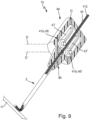
- FIG. 9 an application situation of the cannula arrangement 1b is shown in which the guide wire S abuts against a schematically shown obstacle H.
- a proximal retraction movement of the guide wire S is usually required.
- the locking rollers 46, 46 ⁇ are rotated in opposite directions about the respective axis of rotation D, D'.
- a displacement in the proximal direction takes place along the respective guide axis X, X'.
- the medical functional strand F or the guide wire S is not necessarily part of the cannula arrangements 1, 1a, 1b.
Landscapes
- Health & Medical Sciences (AREA)
- Life Sciences & Earth Sciences (AREA)
- Surgery (AREA)
- General Health & Medical Sciences (AREA)
- Public Health (AREA)
- Engineering & Computer Science (AREA)
- Biomedical Technology (AREA)
- Heart & Thoracic Surgery (AREA)
- Veterinary Medicine (AREA)
- Animal Behavior & Ethology (AREA)
- Medical Informatics (AREA)
- Pathology (AREA)
- Nuclear Medicine, Radiotherapy & Molecular Imaging (AREA)
- Molecular Biology (AREA)
- Pulmonology (AREA)
- Hematology (AREA)
- Biophysics (AREA)
- Anesthesiology (AREA)
- Infusion, Injection, And Reservoir Apparatuses (AREA)
- Media Introduction/Drainage Providing Device (AREA)
Description
- Die Erfindung betrifft eine Kanülenanordnung, aufweisend ein längserstrecktes Kanülenrohr mit einer proximalen Eintrittsöffnung, einer distalen Austrittsöffnung, einem zwischen der Eintrittsöffnung und der Austrittsöffnung durchgängig längserstreckten Lumen und mit einer die Austrittsöffnung berandenden angeschärften Kanülenspitze, wobei das Kanülenrohr eingerichtet ist zur Aufnahme und Führung eines biegeflexiblen medizinischen Funktionsstrangs, der in das Lumen einführbar und entlang des Lumens beweglich ist. Kanülenanordnungen sind in der medizinischen Praxis allgemein bekannt und werden unter anderem zur Punktion von menschlichem oder tierischem Körpergewebe sowie zum anschließenden Einbringen und/oder Entnehmen von Flüssigkeiten verwendet.
- Zu diesem Zweck weisen übliche Kanülenanordnungen ein längserstrecktes Kanülenrohr mit einer proximalen Eintrittsöffnung und einer distalen Austrittsöffnung auf. Zwischen der Ein- und der Austrittsöffnung ist ein durchgängig längserstrecktes Lumen vorgesehen. Die Austrittsöffnung wird von einer angeschärften Kanülenspitze berandet, die oftmals auch als Anschliff oder Kanülenauge bezeichnet wird. Die angeschärfte Kanülenspitze erleichtert das Punktieren des Körpergewebes.
- Überdies sind unterschiedliche medizinische Anwendungsfälle bekannt, in welchen das Kanülenrohr als Mandrin für einen in den Körper einzuführenden medizinischen Funktionsstrang dient. Der medizinische Funktionsstrang kann beispielsweise eine längserstreckte Sonde, ein Lichtleiter, ein Führungsdraht oder dergleichen sein.
- Die
US 2015/297213 A1 offenbart eine medizinische Kanülenanordnung zur perkutanen Fixierung des Magens eines Patienten. Die Kanülenanordnung weist eine Nadel mit einer Nadelnabe an ihrem proximalen Ende und ein Stilett mit einer Stilettnabe an ihrem proximalen Ende auf. Laschen in der Nadelnabe blockieren die proximal gerichtete Rückzugsbewegung des Stiletts. - Die
US 2009/259126 A1 offenbart eine Kanülenanordnung zur Abgabe von Arzneimitteln in den Halsbereich der Wirbelsäule eines Patienten mit einer Kanüle, einer Nabe am proximalen Ende der Kanüle und einem in die Kanüle verschiebbaren Injektionsschlauch. Eine proximal gerichtete Rückzugsbewegung des Injektionsschlauchs wird durch eine interne Konstruktion der Nabe blockiert. - Die
DE 32 21 244 A1 offenbart eine Vorrichtung zum Einführen eines langgestreckten Gegenstandes, insbesondere eines Katheters, einer Sonde oder dergleichen, in eine Körperhöhle, bestehend aus einem gegebenenfalls längsteilbaren Führungsstück mit einem an beiden Enden offenen Durchlaß und einer in den Durchlaß eingebauten Rückzugsperre für den langgestreckten Gegenstand. -
DE 21 09 608 A1 offenbart eine Vorrichtung zur Einführung eines Katheters in ein Blutgefäß und insbesondere zum Bewegen eines Katheters in einem Blutgefäß. - Die
WO2020231455 A1 offenbart ein Gefäßzugangsgerät mit integrierten Sicherheitsvorrichtungen, die die Migration von Führungsdrahten in den Körper des Patienten verhindern. - Ein wichtiger Anwendungsfall ist die Anlage zentralvenöser Katheter nach der sogenannten Seldinger-Technik. Diese sieht insbesondere vor, dass ein Führungsdraht in die Eintrittsöffnung des Kanülenrohrs eingeführt, in distaler Vorschubrichtung durch das Lumen vorgeschoben und aus der Austrittsöffnung ausgeführt wird.
- Aufgabe der Erfindung ist es, eine Kanülenanordnung der eingangs genannten Art bereitzustellen, die eine erhöhte Patientensicherheit bietet.
- Diese Aufgabe wird durch eine Kanülenanordnung gemäss Anspruch 1 gelöst.
- Weitere Ausführungsformen der Erfindung sind in den abhängigen Ansprüchen definiert.
- Die Erfindung geht von der Erkenntnis aus, dass der medizinische Funktionsstrang bei einer proximalen Rückzugbewegung, d.h. bei einem Zurückziehen durch das Kanülenrohr, beschädigt oder gar durchtrennt werden kann. Denn bei dem Zurückziehen kann der Funktionsstrang unter Umständen an der die Austrittsöffnung berandenden angeschärften Kanülenspitze zur Anlage gelangen, wobei die angeschärfte Kanülenspitze als eine Art Schneide auf den Funktionsstrang einwirken kann. Dies kann zu schwerwiegenden Komplikationen führen. Unter Umständen kann eine Notfalloperation zum Entfernen des teilweise abgetrennten Funktionsstrangs aus dem Körper notwendig werden. Um alldem entgegenzuwirken, sieht die erfindungsgemäße Lösung die Sperrvorrichtung vor. Die Sperrvorrichtung bewirkt eine Sperrung der Beweglichkeit des Funktionsstrangs in proximaler Richtung, so dass der Funktionsstrang zwar ohne weiteres in distaler Richtung vorgeschoben, jedoch nicht oder lediglich in begrenztem Umfang in proximaler Richtung zurückgezogen werden kann. Hierdurch wird einer Beschädigung des Funktionsstrangs durch die angeschärfte Kanülenspitze entgegenwirkt und letztlich eine verbesserte Patientensicherheit erreicht. Vorzugsweise wirkt die Sperrvorrichtung mechanisch mit dem Funktionsstrang zusammen, so dass auch von einer mechanischen Sperrvorrichtung gesprochen werden kann. Alternativ oder zusätzlich kann die Sperrvorrichtung magnetisch und/oder elektrisch mit dem Funktionsstrang zusammenwirken. Zum Sperren der Beweglichkeit des Funktionsstrangs weist die Sperrvorrichtung das wenigstens eine dem Lumen zugeordnete Sperrelement auf. Das wenigstens eine Sperrelement ist unter Einwirkung des in das Lumen eingeführten Funktionsstrangs und in Abhängigkeit der jeweiligen Bewegungsrichtung zwischen der Freigabe- und der Sperrstellung selbsttätig überführbar. Das Überführen zwischen der Freigabe- und der Sperrstellung kann eine elastische Deformation, insbesondere Biegedeformation, und/oder eine, insbesondere translatorische und/oder rotatorische, Starrkörperbewegung des wenigstens einen Sperrelements umfassen. In der Sperrstellung wirkt das wenigstens eine Sperrelement auf den Funktionsstrang, so dass eine proximale Verlagerung oder jedenfalls eine weitergehende proximale Verlagerung des Funktionsstrangs durch das Lumen unterbunden ist. Vorzugsweise wirkt das wenigstens eine Sperrelement in der Sperrstellung kraft- und/oder formschlüssig auf eine Außenfläche des Funktionsstrangs ein. Selbsttätig meint, dass das Überführen bzw. der Wechsel zwischen der Freigabe- und der Sperrstellung je nach Bewegungsrichtung des Funktionsstrangs gleichsam automatisch und insbesondere ohne gesonderten Eingriff von außen erfolgt. Vorzugsweise ist das wenigstens eine Sperrelement in der Freigabestellung relativ zu dem Lumen radial nach außen verlagert. Weiter vorzugsweise ist das wenigstens eine Sperrelement in der Sperrstellung relativ zu dem Lumen radial nach innen verlagert. In einem Anwendungszustand derKanülenanordnung, in welchem der medizinische Funktionsstrang in das Lumen eingeführt ist, wirkt das wenigstens eine Sperrelement vorzugsweise mechanisch mit der Außenfläche des Funktionsstrangs zusammen. Vorzugsweise wirkt das wenigstens eine Sperrelement in der Sperrstellung proximal entlang einer Längsachse des Lumens - und damit entlang einer Längsachse des Funktionsstrangs - kraft- und/oder formschlüssig auf den Funktionsstrang, genauer: dessen Außenfläche und/oder Mantelfläche, ein. In der Freigabestellung ist diese Einwirkung aufgehoben. Der medizinische Funktionsstrang ist nicht Bestandteil der erfindungsgemäßenKanülenanordnung. Ausgestaltungen der erfindungsgemäßen Kanülenanordnung können einen bzw. den medizinischen Funktionsstrang umfassen. Der medizinische Funktionsstrang ist längserstreckt und biegeflexibel und kann insbesondere ein medizinischer Draht, wie beispielsweise ein Führungsdraht zur Katheteranlage, eine medizinische Sonde, ein Lichtleiter, eine Faden- oder Drahtanordnung, die jeweils verzwirnt und/oder verdrillt sein kann, oder dergleichen sein.
- In Ausgestaltung der Erfindung ist die Sperrvorrichtung in das Kanülenrohr integriert.
- Eine Integration der Sperrvorrichtung in das Kanülenrohr ermöglicht insbesondere einen besonders kompakten Aufbau der Kanülenanordnung. Dabei kann das wenigstens eine Sperrelement insbesondere durch einen Rohrwandabschnitt einer Rohrwandung des Kanülenrohrs gebildet sein. Alternativ kann das wenigstens eine Sperrelement separat von dem Kanülenrohr gefertigt und hiernach in dieses eingesetzt und/oder integriert sein. Eine Integration der Sperrvorrichtung in den Kanülenansatz bietet vergleichsweise mehr Bauraum und eröffnet insoweit weitere konstruktive Freiheitsgrade im Hinblick auf die räumlich-körperliche Gestaltung der Sperrvorrichtung und/oder des wenigstens einen Sperrelements. Der Kanülenansatz kann auch als Kanülenhub bezeichnet werden und ist proximal an dem Kanülenrohr befestigt. Abgesehen von der integrierten Sperrvorrichtung weist der Kanülenansatz vorzugsweise einen üblichen Aufbau auf, so dass insbesondere ein proximal angeordneter Anschlussport zum Anschließen einer fluidführenden Komponente an den Kanülenansatz vorhanden sein kann. Der Anschlussport kann beispielsweise als Luer-Anschluss ausgestaltet sein. Vorzugsweise ist der Kanülenansatz unlösbar mit dem Kanülenrohr zusammengefügt. Bei dieser Ausgestaltung der Erfindung ist der Kanülenansatz Bestandteil der Kanülenanordnung. Das besagte Vorrichtungsgehäuse erlaubt einen besonders flexiblen Einsatz der Sperrvorrichtung. Das Vorrichtungsgehäuse ist proximal an dem Kanülenrohr befestigt und/oder befestigbar. Sofern die Kanülenanordnung einen Kanülenansatz aufweist, ist das Vorrichtungsgehäuse proximal an dem Kanülenansatz befestigt und/oder befestigbar. Die jeweilige Befestigung ist vorzugsweise lösbar gestaltet. Sofern ein Kanülenansatz und/oder ein Vorrichtungsgehäuse vorhanden sind, ist der Funktionsstrang - in einem Anwendungszustand der Kanülenanordnung - durch ein jeweiliges Lumen des Katheteransatzes und/oder des Vorrichtungsgehäuses längserstreckt.
- In weiterer Ausgestaltung der Erfindung ist das wenigstens eine Sperrelement eine Sperrklinke, die elastisch federbeweglich und/oder schwenkbeweglich zwischen der Freigabestellung und der Sperrstellung verlagerbar ist und eine in distaler Richtung ausgerichtete Sperrkante aufweist, die bei einer Vorschubbewegung relativ gleitbeweglich mit einer Außenfläche des Funktionsstrangs zusammenwirkt und bei einer Rückzugbewegung reibkraftbedingt gegen die Außenfläche angestellt ist und die Rückzugbewegung kraft- und/oder formschlüssig sperrt. Diese Ausgestaltung der Erfindung ermöglicht einen besonders einfachen Aufbau der Sperrvorrichtung. Die Sperrklinke ist in das Kanülenrohr integriert.
- Die Sperrklinke wirkt mittels ihrer Sperrkante mechanisch mit der Außenfläche des Funktionsstrangs zusammen. Die Außenfläche kann auch als Mantelfläche bezeichnet werden. Um eine richtungsabhängige Verlagerung zwischen der Freigabe- und der Sperrstellung zu ermöglichen, ist die Sperrkante in distaler Richtung ausgerichtet. Infolge dieser distalen Ausrichtung bewirkt eine zwischen der Sperrkante und der Außenfläche bewegungsbedingt auftretende Reibkraft entweder eine in Radialrichtung des Lumens nach außen oder nach innen wirkende Kraftkomponente. Die radial nach außen wirkende Kraftkomponente tritt bei der distalen Vorschubbewegung auf. Hierdurch wird die Sperrkante unter Einwirkung der Außenfläche radial nach außen gedrückt. Die radial nach innen wirkende Kraftkomponente tritt bei der proximalen Rückzugbewegung auf. Hierdurch wird die Sperrkante radial nach innen auf den Funktionsstrang, genauer: dessen Außenfläche, gedrückt. Insoweit kann auch von einer Selbstverstärkung und/oder Selbsthemmung gesprochen werden. Durch die radial nach innen wirkende Kraftkomponente kommt zu einem Kraft- und/oder Formschluss zwischen der Sperrkante und der Außenfläche.
- In weiterer Ausgestaltung der Erfindung ist die Sperrklinke nach Art einer Biegefeder gestaltet, wobei die Biegefeder einends relativ zu dem Lumen festgelegt ist und andernends die Sperrkante aufweist. Die Biegefeder ist elastisch federbeweglich zwischen der Freigabe- und der Sperrstellung. Hierdurch kann insbesondere auf eine Schwenk- oder ansonsten bewegliche Lagerung der Sperrklinke verzichtet werden. Dies erlaubt eine weitere Vereinfachung der Konstruktion.
- In weiterer Ausgestaltung der Erfindung ist die Sperrklinke durch einen zungenförmig freigestellten Rohrwandabschnitt einer Rohrwandung des Kanülenrohres gebildet. Dies erlaubt einen besonders kompakten und einfachen Aufbau der Kanülenanordnung. Zum einen ist bei dieser Ausgestaltung der Erfindung kein gesonderter Bauraum für das wenigstens eine Sperrelement, genauer: die Sperrklinke, erforderlich. Zum anderen sind keine zusätzlichen Bauteile zum Ausbilden der, vorzugsweise mechanischen, Sperrvorrichtung erforderlich. Vielmehr bildet das Kanülenrohr selbst gleichsam die, vorzugsweise mechanische, Sperrvorrichtung. Zu diesem Zweck bildet der zungenförmig freigestellte Rohrwandabschnitt die Sperrklinke aus. Zungenförmig freigestellt meint, dass die Rohrwandung in Radialrichtung mittels eines im weitesten Sinne U-förmigen Einschnitts durchtrennt ist. Der mittels des Einschnitts freigestellte Rohrwandabschnitt weist insoweit im weitesten Sinne eine Zungenform auf. Einends, im Bereich der "Zungenwurzel" ist der Rohrwandabschnitt einstückig zusammenhängend mit der übrigen Rohrwandung. Andernends, im Bereich der "Zungenspitze", weist der Rohrwandabschnitt die Sperrkante auf. Der freigestellte Rohrwandabschnitt ist elastisch federbeweglich zwischen der Freigabe- und der Sperrstellung.
- In weiterer Ausgestaltung der Offenbarung ist das wenigstens eine Sperrelement eine um eine Drehachse drehbeweglich gelagerte erste Sperrrolle, deren Außenumfang zum Abwälzen auf dem Funktionsstrang eingerichtet ist, wobei die erste Sperrrolle eine mit der Vorschubbewegung korrespondierende Freilaufdrehrichtung sowie eine entgegengesetzt um die Drehachse gerichtete und mit der Rückzugbewegung korrespondierende Blockierrichtung aufweist. Der Außenumfang der ersten Sperrrolle wirkt radial und/oder tangential mit der Außenfläche des Funktionsstrangs zusammen. Die Drehachse der ersten Sperrrolle ist orthogonal zur Längsachse des Lumens - und damit des Funktionsstrangs - orientiert. Die Ausgestaltung des wenigstens einen Sperrelement als Sperrrolle erlaubt im Vergleich zu einer Ausgestaltung als Sperrklinke insbesondere eine leichtgängigere Vorschubbewegung und eine verminderte Beanspruchung des Funktionsstrangs. Denn der Außenumfang wälzt bei der Vorschubbewegung auf dem Funktionsstrang und/oder dessen Außenfläche ab. Hierbei kommt es lediglich zu einer Rollreibung. Dementgegen tritt bei der Sperrklinke eine Gleitreibung auf. Die auf diese Weise verminderte Reibungseinwirkung erlaubt zum einen die besagte leichtgängige Vorschubbewegung und zum anderen eine verminderte Beanspruchung des Funktionsstrangs. In der Blockierrichtung ist keine Drehbewegung der Sperrrolle möglich. Dementsprechend wirkt der Außenumfang dann unter Sperrung der proximalen Beweglichkeit des Funktionsstrangs kraft- und/oder formschlüssig auf dessen Außenfläche ein.
- In weiterer Ausgestaltung der Offenbarung ist die erste Sperrrolle entlang einer ersten Führungsachse an einer ersten Linearführung linearbeweglich geführt verlagerbar, wobei die erste Führungsachse relativ zu einer Längsachse des Lumens geneigt ist, und wobei die erste Sperrrolle unter Einwirkung des Funktionsstrangs entlang der ersten Führungsachse beweglich ist, wodurch der Außenumfang relativ zu dem Funktionsstrang radial nach außen und/oder nach innen verlagerbar ist. Die erste Führungsachse ist relativ zu der Längsachse des Lumens in proximaler Richtung radial nach innen geneigt. Bei einem Zurückziehen des Funktionsstrangs wird die erste Sperrrolle entlang der ersten Führungsachse proximal verlagert, wodurch deren Außenumfang radial nach innen gegen den Funktionsstrang angestellt wird. Dieses Anstellen oder auch Andrücken bewirkt letztlich eine Sperrung der Rückzugbewegung.
- In weiterer Ausgestaltung der Offenbarung ist eine zweite Sperrrolle vorhanden und in Radialrichtung des Lumens gegenüber der ersten Sperrrolle angeordnet, wobei die zweite Sperrrolle an einer zweiten Linearführung entlang einer zweiten Führungsachse linearbeweglich geführt verlagerbar ist, wobei die zweite Führungsachse in Bezug auf die Längsachse des Lumens spiegelsymmetrisch zu der ersten Führungsachse orientiert ist. Diese Ausgestaltung der Offenbarung erlaubt eine besonders zuverlässige Sperrung der Rückzugsbewegung. Denn der Funktionsstrang wird bei einem Zurückziehen gleichsam zwischen der ersten Sperrrolle und der zweiten Sperrrolle radial eingeklemmt. Die erste Sperrrolle und die zweite Sperrrolle bilden vorzugsweise ein Sperrrollenpaar. Bei einer weiteren Ausgestaltung sind mehr als zwei Sperrrollen vorhanden und vorzugsweise unter Ausbildung eines Sperrrollenpakets, bevorzugt sternförmig in Bezug auf den Funktionsstrang, angeordnet.
- In weiterer Ausgestaltung der Offenbarung ist wenigstens die erste Sperrrolle dreh- und/oder linearbeweglich in dem Vorrichtungsgehäuse aufgenommen. Grundsätzlich denkbar ist zudem eine Integration der ersten Sperrrolle und/oder der zweiten Sperrrolle in das Kanülenrohr oder einen etwaigen Kanülenansatz. Allerdings bietet die Aufnahme in dem Vorrichtungsgehäuse konstruktive Vorteile, da vergleichsweise mehr Bauraum vorgesehen werden kann und übliche Dimensionen des Kanülenrohrs und/oder des Kanülenansatzes beibehalten werden können.
- In weiterer Ausgestaltung der Erfindung umfasst die Kanülenanordnung den medizinischen Funktionsstrang. Vorzugsweise ist der medizinische Funktionsstrang ein medizinischer Draht, bevorzugt ein Seldinger-Draht.
- Weitere Vorteile und Merkmale der Erfindung ergeben sich aus den Ansprüchen und der nachfolgenden Beschreibung bevorzugter Ausführungsbeispiele der Erfindung, die anhand der Zeichnungen dargestellt sind.
- Fig. 1
- zeigt in teilweise abgeschnittener, schematischer Perspektivdarstellung eine aus dem Stand der Technik bekannte Kanülenanordnung im Bereich einer angeschärften Kanülenspitze mitsamt eines medizinischen Funktionsstrangs in Form eines Führungsdrahts,
- Fig. 2
- in perspektivischer sowie teilweise aufgeschnittener Darstellung eine Ausführungsform einer nicht beanspruchten Kanülenanordnung mit einem Kanülenrohr, einem Kanülenansatz und einer in den Kanülenansatz integrierten mechanischen Sperrvorrichtung,
- Fig. 3
- eine vergrößerte Detaildarstellung der Kanülenanordnung nach
Fig. 2 mit Blickrichtung auf die Sperrvorrichtung in einer Freigabestellung und bei einer distal gerichteten Vorschubbewegung eines Führungsdrahts, - Fig. 4
- die Kanülenanordnung nach den
Fig. 2 und3 in einer derFig. 3 entsprechenden Darstellungsweise in einer Sperrstellung der Sperrvorrichtung und bei einer proximal gerichteten Rückzugbewegung des Führungsdrahts, - Fig. 5
- in teilweise aufgeschnittener, schematischer Perspektivdarstellung eine Ausführungsform einer erfindungsgemäßen Kanülenanordnung mit einer in das Kanülenrohr integrierten Sperrvorrichtung,
- Fig. 6
- eine vergrößerte perspektivische Detaildarstellung der Kanülenanordnung nach
Fig. 5 im Bereich der Sperrvorrichtung, - Fig. 7
- eine weitere perspektivische und teilweise aufgeschnittene Detaildarstellung der Kanülenanordnung nach den
Fig. 5 und6 im Bereich der Sperrvorrichtung, - Fig. 8
- in teilweise aufgeschnittener, schematischer Perspektivdarstellung eine weitere Ausführungsform einer nicht beanspruchten Kanülenanordnung, deren Sperrvorrichtung zwei Sperrrollen umfasst,
- Fig. 9
- die Kanülenanordnung nach
Fig. 8 in einem weiteren Anwendungszustand und - Fig. 10
- die Kanülenanordnung nach den
Fig. 8 und9 in einer Sperrstellung der Sperrvorrichtung. - Anhand
Fig. 1 ist bereichsweise und schematisch stark vereinfacht eine aus dem Stand der Technik bekannte Kanülenanordnung 100 mit einem längserstreckten Kanülenrohr 200 gezeigt. Das Kanülenrohr 200 weist eine nicht näher zeichnerisch dargestellte proximale Eintrittsöffnung 201, eine distale Austrittsöffnung 202, ein zwischen der Eintrittsöffnung 201 und der Austrittsöffnung 202 durchgängig längserstrecktes Lumen 203 und eine die Austrittsöffnung 202 berandende angeschärfte Kanülenspitze 204 auf. Die angeschärfte Kanülenspitze 204 erleichtert eine Punktion von tierischem oder menschlichem Körpergewebe und kann auch als Anschliff oder Kanülenauge bezeichnet werden. Weiter ist anhandFig. 1 ein biegeflexibler medizinischer Funktionsstrang F in Gestalt eines Führungsdrahts S gezeigt. Der Führungsdraht S kann auch als Seldinger-Draht bezeichnet werden und weist eine dem Fachmann bekannte Funktionsweise und Gestaltung auf. Der Führungsdraht S ist einends in die Eintrittsöffnung 201 eingeführt, entlang des Lumens 203 vorgeschoben und ragt in der anhandFig. 1 gezeigten Konfiguration stirnendseitig aus der Austrittsöffnung 202 heraus. Zudem ist der Führungsdraht S in einem stirnendseitig biegedeformierten Zustand gezeigt, wie er sich beispielsweise durch ein Anlaufen des Führungsdrahts S an ein gewebeseitiges Hindernis, wie beispielsweise eine Venenwand, eine Organwand oder dergleichen, einstellen kann. - Ausgehend von der anhand
Fig. 1 gezeigten Konfiguration kann es bei einer in proximaler Richtung gerichteten Rückzugbewegung des Führungsdrahts S zu einer Beschädigung desselben durch die Kanülenspitze 204 kommen. Wird der Führungsdraht S zurückgezogen, wirkt die durch die Kanülenspitze 204 gebildete Berandung der Austrittsöffnung 202 nach Art einer Schneide auf den Führungsdraht S ein. Hierdurch kann der Führungsdraht S schlechtestenfalls durchtrennt werden, was mit schwerwiegenden medizinischen Komplikationen einhergehen kann. - Um solche Komplikationen zu vermeiden, weist die anhand der
Fig. 2 ,3 und 4 gezeigte Kanülenanordnung 1 eine mechanische Sperrvorrichtung 4 auf, die auf noch näher beschriebene Weise eine proximal gerichtete Rückzugbewegung des Funktionsstrangs F selbsttätig sperrt. Bevor auf die weiteren Einzelheiten und die Funktionsweise der mechanischen Sperrvorrichtung 4 im Detail eingegangen wird, werden zunächst weitere räumlich-körperliche und funktionelle Merkmale der Kanülenanordnung 1 erläutert:
Die Kanülenanordnung 1 weist ein längserstrecktes Kanülenrohr 2 mit einer proximalen Eintrittsöffnung 21 und einer distalen Austrittsöffnung 22 auf. Die proximale Eintrittsöffnung 21 und die distale Austrittsöffnung 22 sind mittels eines durchgängig längserstreckten Lumens 23 miteinander verbunden. Distal angeordnet weist das Kanülenrohr 2 eine angeschärfte Kanülenspitze 24 auf, welche die Austrittsöffnung 22 berandet. Das Kanülenrohr 2 ist zur Aufnahme und Führung des biegeflexiblen medizinischen Funktionsstrangs F, der anhandFig. 2 wiederum als Führungsdraht S dargestellt ist, eingerichtet. Insoweit ist die Gestaltung des Kanülenrohrs 2 grundsätzlich übereinstimmend mit der Gestaltung des aus dem Stand der Technik bekannten Kanülenrohrs 200. - Weiter weist die Kanülenanordnung 1 einen Kanülenansatz 3 auf. Der Kanülenansatz 3 trägt das Kanülenrohr 2 und ist auf eine dem Fachmann bekannte Weise an ein der Kanülenspitze 24 abgewandtes Kanülenende 25 des Kanülenrohrs 2 angefügt. Der Kanülenansatz 3 ist zwischen einem nicht näher bezeichneten proximalen Ende und einem nicht näher bezeichneten distalen Ende längserstreckt und weist ein durchgängig längserstrecktes Lumen 31 auf, das einends in die Eintrittsöffnung 21 des Kanülenrohres 2 mündet. Das Lumen 31 des Kanülenansatzes 3 und das Lumen 23 des Kanülenrohrs 2 sind zueinander koaxial längserstreckt. Die übrige anhand
Fig. 2 ersichtliche Formgebung des Kanülenansatzes 3 ist im Hinblick auf die vorliegende Erfindung nicht von vornehmlicher Bedeutung, so dass weitere diesbezügliche Erläuterungen entbehrlich sind. - Wie weiter anhand
Fig. 2 gezeigt ist, ist der Führungsdraht S ausgehend von dem proximalen Ende des Kanülenansatzes 3 in dessen Lumen 31 und ausgehend von diesem über die Eintrittsöffnung 21 in das Lumen 23 des Kanülenrohrs 2 und von dort weiter bis in eine über die Austrittsöffnung 22 hinausgehende Konfiguration vorschiebbar. Die Vorschubbewegung erfolgt hierbei in distaler Richtung entlang einer Längsachse L des Lumens 23, die bei der gezeigten Ausführungsform koaxial mit der Längsachse des Kanülenrohrs und des Lumens 31 ist. - Die mechanische Sperrvorrichtung 4 ist bei der anhand der
Fig. 2 bis 4 gezeigten Ausführungsform in den Kanülenansatz 3 integriert. Zudem weist die mechanische Sperrvorrichtung 4 ein dem Lumen 23 zugeordnetes Sperrelement 41 auf. Das Sperrelement 41 ist zum mechanischen Zusammenwirken mit dem Funktionsstrang F, genauer: des Führungsdrahts S, eingerichtet. Dabei wirkt das Sperrelement 41 mit einer Außenfläche M des Funktionsstrangs F zusammen, die auch als Mantelfläche bezeichnet werden kann. In Abhängigkeit der Bewegungsrichtung des Funktionsstrangs F ist das Sperrelement 41 selbsttätig überführbar zwischen einer Sperrstellung (Fig. 4 ) und einer Freigabestellung (Fig. 3 ). In der Sperrstellung sperrt das Sperrelement 41 eine proximal gerichtete Rückzugbewegung des Funktionsstrangs F. Hierzu wirkt das Sperrelement 41 kraft- und/oder formschlüssig auf die Außenfläche M ein. Dementgegen ist diese Einwirkung bzw. Sperrung in der Freigabestellung aufgehoben. - Die anhand der
Fig. 3 und 4 ersichtlichen Pfeile symbolisieren eine distal gerichtete Vorschubbewegung V und eine proximal gerichtete Rückzugbewegung R. - Bei der gezeigten Ausführungsform ist das Sperrelement 41 eine Sperrklinke 42, die elastisch federbeweglich zwischen der Sperr- und der Freigabestellung verlagerbar ist. Die Sperrklinke 42 ist vorliegend eine separat von dem Kanülenansatz 3 gefertigte und hiernach in diesen integrierte Biegefeder 43. Die Biegefeder 43 ist einends, an einem radial außen liegenden Stirnende 44, in einer nicht näher bezeichneten Aufnahmeaussparung des Kanülenansatzes 3 festgelegt. Beispielsweise kann das Stirnende 44 kraft-, form- und/oder stoffschlüssig in der Aufnahmeaussparung festgelegt sein.
- Bei einer zeichnerisch nicht näher dargestellten Ausführungsform ist die Sperrklinke 42 und/oder die Biegefeder 43 durch einen Abschnitt des Kanülenansatzes gebildet und insoweit einstückig zusammenhängend mit den übrigen Abschnitten des Kanülenansatzes.
- Radial andernends weist die Sperrklinke 42 in Form der Biegefeder 43 eine Sperrkante 45 auf. Die Sperrkante 45 ist in distaler Richtung ausgerichtet. Bei der Vorschubbewegung V gleitet die Außenfläche M in distaler Richtung entlang der Sperrkante 45. Aufgrund der distalen Ausrichtung der Sperrkante 45 bewirkt die hierbei auftretende Reibungskraft eine radial nach außen gerichtete Kraftkomponente auf die Sperrkante 45. Dies wirkt einem Verklemmen der Sperrkante 45 an der Außenfläche M entgegen und gewährleistet eine leichtgängige Vorschubbewegung V.
- Bei einer Rückzugbewegung R (
Fig. 4 ) bewirkt die zwischen dem Funktionsstrang, genauer dessen Außenfläche M, und der Sperrkante 45 auftretende Reibungskraft eine in radialer Richtung nach innen orientierte Kraftkomponente. Diese radial nach innen gerichtete Kraftkomponente bewirkt, dass die Sperrkante 45 in radialer Richtung auf die Außenfläche M gepresst wird. Letztlich wird hierdurch ein Kraft- und/oder Formschluss mit der Außenfläche M und eine Sperrung der Rückzugbewegung R bewirkt. - Im Übrigen ist die Sperrklinke 42 und/oder die Biegefeder 43 bei der gezeigten Ausführungsform aus einem federelastischen Elastomerwerkstoff gefertigt. Denkbar ist zudem eine Fertigung aus Federstahl oder dergleichen.
- Bei einer zeichnerisch nicht dargestellten Ausführungsform kann die Sperrklinke alternativ oder zusätzlich schwenkbeweglich zwischen der Freigabe- und der Sperrstellung verlagerbar sein. Dementsprechend ist nicht zwingend eine federelastische Gestaltung der Sperrklinke erforderlich. Stattdessen kann die Sperrklinke einends mittels eines Schwenklagers schwenkbeweglich an dem Katheteransatz oder dem Kanülenrohr gelagert sein.
- Anhand der
Fig. 5 bis 7 ist eine Ausführungsform einer erfindungsgemäßen Kanülenanordnung 1a gezeigt. Nachfolgend wird lediglich auf wesentliche Unterschiede der Kanülenanordnung 1a gegenüber der Kanülenanordnung 1 nach denFig. 2 bis 4 eingegangen. Wesentlicher Unterschied der Kanülenanordnung 1a ist, dass die mechanische Sperrvorrichtung 4a in das Kanülenrohr 2a integriert ist. Abgesehen von der Integration der Sperrvorrichtung 4a weist das Kanülenrohr 2a eine mit dem Kanülenrohr 2 der Kanülenanordnung 1 weitestgehend identische Gestaltung und/oder Funktion auf. Zudem ist an dem Kanülenende 25a des Kanülenrohrs 2a wiederum ein Kanülenansatz 3a befestigt. Der Kanülenansatz 3a weist - mit Ausnahme der nun nicht vorhandenen, integrierten mechanischen Sperrvorrichtung 4 - eine mit dem Kanülenansatz 3 identischen Aufbau auf. Weitere Erläuterungen zu dem Kanülenansatz 3a und der grundlegenden Gestaltung des Kanülenrohrs 2a sind daher entbehrlich. - Auch bei der Ausführungsform nach den
Fig. 5 bis 7 weist die mechanische Sperrvorrichtung 4a ein Sperrelement 41a in Form einer Sperrklinke 42a auf. Dabei ist die Sperrklinke 42a durch einen zungenförmig freigestellten Rohrwandabschnitt 261 einer Rohrwandung 26 des Kanülenrohrs 2a gebildet. Der Rohrwandabschnitt 261 ist mittels eines im Wesentlichen U-förmigen und radial durch die Rohrwandung 26 erstreckten Einschnitts von angrenzenden Bereichen der Rohrwandung 26 freigestellt. Dementsprechend weist der Rohrwandabschnitt 261 ein einstückig mit der übrigen Rohrwandung 26 verbundenes erstes Stirnende 262 und ein gegenüberliegendes zweites Stirnende 263 auf. Das zweite Stirnende 263 ist in radialer Richtung des Kanülenrohrs 2a relativbeweglich zu den übrigen Abschnitten der Rohrwandung 26. Das erste Stirnende 262 ist proximal angeordnet. Das zweite Stirnende 263 ist distal angeordnet. An seinem zweiten Stirnende 263 weist die Sperrklinke 42a bzw. der Rohrwandabschnitt 262 eine radial innenliegende Sperrkante 45a auf, die jedenfalls abschnittsweise anhandFig. 7 gezeigt ist. Die Sperrkante 45a wirkt in einer der Sperrkante 45 entsprechenden Weise mit der Außenfläche M des Führungsdrahts S zusammen. - Im Übrigen sind einander gegenüberliegende Längskanten 264, 265 des zungenförmigen Rohrwandabschnitts 261 parallel zur Längsachse L des Lumens 23a erstreckt. In Querrichtung und damit in Umfangsrichtung des Kanülenrohrs 2a ist eine Querkante 266 zwischen den beiden Längskanten 264, 265 erstreckt. Die Querkante 266 weist eine proximale Einbuchtung auf, die dementsprechend auch bei der Sperrkante 45a vorhanden ist. Dies führt zu einem verbesserten Formschluss an der Außenfläche M.
- Eine weitere Ausführungsform einer Kanülenanordnung 1b ist anhand der
Fig. 8 bis 10 gezeigt. Zur Vermeidung von Wiederholungen werden wiederum lediglich wesentliche Unterschiede der Kanülenanordnung 1b gegenüber den vorhergehenden Ausführungsformen erläutert. - Die Kanülenanordnung 1b weist wiederum ein Kanülenrohr 2 und einen Kanülenansatz 3b auf.
- Das Kanülenrohr 2 ist in seiner Gestaltung und Funktion identisch mit dem Kanülenrohr 2 der Ausführungsform nach den
Fig. 2 bis 4 . - Der Kanülenansatz 3b ist wiederum proximal an das Kanülenrohr 2 angefügt.
- Ein wesentlicher Unterschied ist, dass die Sperrvorrichtung 4b der Ausführungsform nach den
Fig. 8 bis 10 weder in das Kanülenrohr 2 noch in den Kanülenansatz 3b integriert ist. Stattdessen weist die mechanische Sperrvorrichtung 4b ein Vorrichtungsgehäuse G auf, in welchem weitere Bauteile und/oder Abschnitte der Sperrvorrichtung 4b aufgenommen sind. - Im Übrigen versteht sich, dass das Vorrichtungsgehäuse G grundsätzlich auch dem Kanülenansatz 3b zugeordnet und insbesondere einstückig zusammenhängend mit diesem verbunden sein kann. Dessen ungeachtet ist das Vorrichtungsgehäuse G bei der gezeigten Ausführungsform auf eine zeichnerisch nicht näher dargestellte Weise form- und/oder kraftschlüssig lösbar proximal an dem Kanülenansatz 3b angefügt. Beispielsweise kann hierfür eine lösbare Rast-, Steck- oder Schraubverbindung vorgesehen sein.
- Ein weiterer wesentlicher Unterschied liegt darin, dass die mechanische Sperrvorrichtung 4b anstelle einer Sperrklinke wenigstens eine Sperrrolle aufweist. Bei der gezeigten Ausführungsform sind eine erste Sperrrolle 46 und eine zweite Sperrrolle 46` vorhanden. Die erste Sperrrolle 46 und die zweite Sperrrolle 46` bilden ein Sperrrollenpaar. Die Gestaltung und Funktion der beiden Sperrrollen 46, 46` ist wenigstens weitestgehend identisch. Zudem sind die beiden Sperrrollen 46, 46' in Bezug auf die Längsachse L des Lumens 23 symmetrisch beidseits des Führungsdrahts S angeordnet. Zur Vermeidung von Wiederholungen wird nachfolgend daher in erster Linie auf die erste Sperrrolle 46 eingegangen. Die diesbezügliche Offenbarung gilt sinngemäß auch für die zweite Sperrrolle 46`, sofern nichts anderes erwähnt ist.
- Die erste Sperrrolle 46 ist um eine Drehachse D drehbeweglich in dem Vorrichtungsgehäuse G gelagert. Die erste Sperrrolle 46 weist einen radial außen liegenden Außenumfang 461 auf, der zum Abwälzen auf der Außenfläche M eingerichtet ist. Dabei weist die erste Sperrrolle 46 eine mit der Vorschubbewegung V korrespondierende Freilaufdrehrichtung auf, die anhand des in
Fig. 8 eingezeichneten Drehrichtungspfeils um die Drehachse D symbolisiert ist. - Weiter ist die erste Sperrrolle 46 entlang einer ersten Führungsachse X an einer Linearführung 47 linearbeweglich geführt verlagerbar. Die erste Führungsachse X ist relativ zu der Längsachse L in proximaler Richtung nach innen geneigt. Diese Neigung ist vergleichsweise gering ausgeführt und daher anhand der vorliegenden Figuren nicht ohne weiteres erkennbar. Die erste Linearführung 47 ist durch nicht näher bezeichnete Führungsspuren gebildet, die einander entlang der Drehachse D gegenüberliegend in dem Vorrichtungsgehäuse G angeordnet sind. Die Führungsspuren wirken mit nicht näher bezeichneten Führungszapfen der ersten Sperrrolle 46 zusammen. Die Führungszapfen sind insoweit entlang der ersten Führungsachse X gleitbeweglich und/oder rollbeweglich in den Führungsspuren aufgenommen und zudem um die - entlang der ersten Führungsachse X verschiebliche - Drehachse D drehbeweglich.
- Die vorhergehenden Erläuterungen in Bezug auf die erste Sperrrolle 46 gelten sinngemäß entsprechend auch für die zweite Sperrrolle 46`. Der zweiten Sperrrolle 46` zugeordnete funktionsgleiche Bauteile und/oder Abschnitte der mechanischen Sperrvorrichtung 4b sind unter Verwendung identischer Bezugszeichenziffern und Hinzufügung eines Apostrophs gekennzeichnet. Insoweit sind insbesondere eine weitere bzw. zweite Drehachse D', eine zweite Führungsachse X' und eine zweite Linearführung 47` vorhanden.
- Die weitere Funktionsweise der mechanischen Sperrvorrichtung 4b kann wie folgt beschrieben werden:
Bei einer Vorschubbewegung V wälzen die Außenumfänge 461, 461` auf der Außenfläche M ab. Dabei stellt sich jeweils die anhand der Drehbewegungspfeile derFig. 8 symbolisierte Drehrichtung um die erste Drehachse D bzw. die zweite Drehachse D' ein. Diese Drehrichtungen sind jeweils als Freilaufdrehrichtungen aufzufassen. Die Sperrrollen 46, 46` nehmen hierbei eine in Bezug auf die jeweilige Linearführung 47 bzw. 47` distale Endlage ein. Dementsprechend sind die nicht näher bezeichneten Führungszapfen distal endseitig an den Linearführungen 47, 47` gehalten, so dass keine weitergehende distale Verlagerung der Sperrrollen 46, 46` entlang der jeweiligen Führungsachse X, X' erfolgen kann. - Anhand
Fig. 9 ist eine Anwendungssituation der Kanülenanordnung 1b gezeigt, in welcher der Führungsdraht S an ein schematisch dargestelltes Hindernis H anstößt. In dieser Konfiguration ist üblicherweise eine proximale Rückzugbewegung des Führungsdrahts S erforderlich. Infolge der Rückzugbewegung werden die Sperrrollen 46, 46` zum einen in jeweils entgegengesetzter Richtung um die jeweilige Drehachse D, D' rotiert. Gleichzeitig erfolgt eine in proximaler Richtung gerichtete Verlagerung entlang der jeweiligen Führungsachse X, X'. Da die beiden Führungsachsen X, X' in proximaler Richtung radial geringfügig nach innen geneigt sind, werden die Sperrrollen 46, 46` infolge ihrer Linearbewegung gleichzeitig radial nach innen gegen den Führungsdraht S angestellt. Dies bewirkt ein verstärktes Anpressen des jeweiligen Außenumfangs 461, 461', was letztlich zu einer Sperrung der Rückzugbewegung führt. - Im Übrigen versteht sich, dass der medizinische Funktionsstrang F bzw. der Führungsdrahts S nicht notwendigerweise Bestandteil der Kanülenanordnungen 1, 1a, 1b ist.
Claims (5)
- Kanülenanordnung (1a), aufweisendein längserstrecktes Kanülenrohr (2a) mit einer proximalen Eintrittsöffnung (21a), einer distalen Austrittsöffnung (22a), einem zwischen der Eintrittsöffnung (21a) und der Austrittsöffnung (22a) durchgängig längserstreckten Lumen (23a) und mit einer die Austrittsöffnung (22a) berandenden angeschärften Kanülenspitze (24a),wobei das Kanülenrohr (2a) eingerichtet ist zur Aufnahme und Führung eines biegeflexiblen medizinischen Funktionsstrangs (F), der in das Lumen (23a) einführbar und entlang des Lumens (23a) beweglich ist,wobei eine Sperrvorrichtung (4a) mit wenigstens einem dem Lumen (23a) zugeordneten Sperrelement (41a) vorhanden ist, wobei das wenigstens eine Sperrelement (41a) zum Zusammenwirken mit dem Funktionsstrang (F) eingerichtet und in Abhängigkeit einer Bewegungsrichtung des Funktionsstrangs (F) selbsttätig überführbar ist zwischen einer Sperrstellung, in welcher das wenigstens eine Sperrelement (41a) eine proximal gerichtete Rückzugbewegung (R) des Funktionsstrangs (F) unter Einwirkung auf den Funktionsstrang (F) sperrt, und einer Freigabestellung, in welcher das wenigstens eine Sperrelement (41a) eine distal gerichtete Vorschubbewegung (V) freigibt, dadurch gekennzeichnet, dass die Sperrvorrichtung (4a) in das Kanülenrohr (2a) integriert ist.
- Kanülenanordnung (1a) nach Anspruch 1, dadurch gekennzeichnet, dass das wenigstens eine Sperrelement (41a) eine Sperrklinke (42a) ist, die elastisch federbeweglich und/oder schwenkbeweglich zwischen der Freigabestellung und der Sperrstellung verlagerbar ist und eine in distaler Richtung ausgerichtete Sperrkante (45a) aufweist, die bei einer Vorschubbewegung (V) gleitbeweglich mit einer Außenfläche (M) des Funktionsstrangs (F) zusammenwirkt und bei einer Rückzugbewegung (R) reibkraftbedingt gegen die Außenfläche (M) angestellt ist und die Rückzugbewegung (R) kraft- und/oder formschlüssig sperrt.
- Kanülenanordnung (1a) nach Anspruch 2, dadurch gekennzeichnet, dass die Sperrklinke (42a) nach Art einer Biegefeder (43) gestaltet ist, wobei die Biegefeder (43) einends relativ zu dem Lumen (23) festgelegt ist und andernends die Sperrkante (45a) aufweist.
- Kanülenanordnung (1a) nach Anspruch 2 oder 3, dadurch gekennzeichnet, dass die Sperrklinke (42a) durch einen zungenförmig freigestellten Rohrwandabschnitt (261) einer Rohrwandung (26) des Kanülenrohrs (2a) gebildet ist.
- Kanülenanordnung (1a) nach einem der vorhergehenden Ansprüche, umfassend den medizinischen Funktionsstrang (F), insbesondere wobei der medizinische Funktionsstrang (F) ein medizinischer Führungsdraht (S), bevorzugt ein Seldinger-Draht, ist.
Applications Claiming Priority (2)
| Application Number | Priority Date | Filing Date | Title |
|---|---|---|---|
| DE102021204780.7A DE102021204780A1 (de) | 2021-05-11 | 2021-05-11 | Kanülenanordnung |
| PCT/EP2022/062538 WO2022238356A1 (de) | 2021-05-11 | 2022-05-10 | Kanülenanordnung |
Publications (2)
| Publication Number | Publication Date |
|---|---|
| EP4337116A1 EP4337116A1 (de) | 2024-03-20 |
| EP4337116B1 true EP4337116B1 (de) | 2024-10-23 |
Family
ID=81975079
Family Applications (1)
| Application Number | Title | Priority Date | Filing Date |
|---|---|---|---|
| EP22728475.9A Active EP4337116B1 (de) | 2021-05-11 | 2022-05-10 | Kanülenanordnung |
Country Status (5)
| Country | Link |
|---|---|
| US (1) | US20240238008A1 (de) |
| EP (1) | EP4337116B1 (de) |
| DE (1) | DE102021204780A1 (de) |
| ES (1) | ES3002357T3 (de) |
| WO (1) | WO2022238356A1 (de) |
Citations (1)
| Publication number | Priority date | Publication date | Assignee | Title |
|---|---|---|---|---|
| WO2020231455A1 (en) * | 2019-05-16 | 2020-11-19 | Dacanay Ventures, Inc. | Vascular access devices with integrated safety features |
Family Cites Families (9)
| Publication number | Priority date | Publication date | Assignee | Title |
|---|---|---|---|---|
| CA935059A (en) * | 1970-02-27 | 1973-10-09 | Jewett-Ashley Holding Corp. | Catheter device |
| DE3221244C2 (de) * | 1982-06-04 | 1985-07-18 | B. Braun Melsungen Ag, 3508 Melsungen | Vorrichtung zum Einführen eines langgestreckten Gegenstandes, insbesondere eines Katheters, einer Sonde oder dergleichen, in eine Körperhöhle |
| DE19542912C2 (de) * | 1995-11-17 | 1999-07-08 | Michael Greive | Einführhilfe zum Strecken eines Führungsdrahts und Sichern des Führungsdrahts in einem Dispenserschlauch und Verbindungselement zum Verbinden der Einführhilfe mit dem Dispenserschlauch |
| WO2003015848A1 (en) * | 2001-08-14 | 2003-02-27 | Applied Medical Resources Corporation | Access sealing apparatus and method |
| DE602006005674D1 (de) | 2005-07-06 | 2009-04-23 | Vascular Pathways Inc | Gerät zur intravenösen kathetereinführung und verwendungsverfahren |
| WO2009124192A1 (en) * | 2008-04-02 | 2009-10-08 | Laurimed, Llc | Methods and devices for delivering injections |
| US8894563B2 (en) * | 2012-08-10 | 2014-11-25 | Attenuex Technologies, Inc. | Methods and systems for performing a medical procedure |
| WO2014133617A1 (en) | 2013-03-01 | 2014-09-04 | C.R. Bard, Inc. | Guidewire extension system for a catheter placement device |
| WO2015160951A1 (en) * | 2014-04-16 | 2015-10-22 | Boston Scientific Scimed, Inc. | Fixation assembly and related methods of use and manufacture |
-
2021
- 2021-05-11 DE DE102021204780.7A patent/DE102021204780A1/de active Pending
-
2022
- 2022-05-10 WO PCT/EP2022/062538 patent/WO2022238356A1/de not_active Ceased
- 2022-05-10 US US18/560,160 patent/US20240238008A1/en active Pending
- 2022-05-10 ES ES22728475T patent/ES3002357T3/es active Active
- 2022-05-10 EP EP22728475.9A patent/EP4337116B1/de active Active
Patent Citations (1)
| Publication number | Priority date | Publication date | Assignee | Title |
|---|---|---|---|---|
| WO2020231455A1 (en) * | 2019-05-16 | 2020-11-19 | Dacanay Ventures, Inc. | Vascular access devices with integrated safety features |
Also Published As
| Publication number | Publication date |
|---|---|
| DE102021204780A1 (de) | 2022-11-17 |
| EP4337116A1 (de) | 2024-03-20 |
| WO2022238356A1 (de) | 2022-11-17 |
| US20240238008A1 (en) | 2024-07-18 |
| ES3002357T3 (en) | 2025-03-06 |
Similar Documents
| Publication | Publication Date | Title |
|---|---|---|
| DE60216467T2 (de) | Schutzvorrichtung für eine nadel | |
| DE102011009482B4 (de) | Sicherheitskanüle | |
| EP0884063B1 (de) | Kathetersystem | |
| DE69320889T2 (de) | Sicherheitsspritze zum Anschliessen an eine intravenöse Zugangsöffnung | |
| DE69218732T2 (de) | Herzschrittmacherleiter mit verbessertem Verankerungsmechanismus | |
| DE69622931T2 (de) | Katheternabe | |
| EP0991444B1 (de) | Kanülenanordnung | |
| DE68911650T2 (de) | Gerät und Methode zur Einführung eines Katheters durch eine Nadel. | |
| EP2052755B1 (de) | Medizinisches Instrument mit seitlich ausspreizbaren Injektionsnadeln | |
| WO2019229206A1 (de) | Steuerbare einführungshülse | |
| DE2238722B2 (de) | Katheter | |
| DE2218901B2 (de) | Trokar zur Einführung von Operationsinstrumenten in Körperhöhlen | |
| WO2016206862A1 (de) | Mehrteilige sicherheitsvorrichtung für eine spritze | |
| DE3218242C2 (de) | Doppelkanüle für die Peridural-Anästhesie | |
| EP3416596B1 (de) | Stent-delivery-system | |
| DE112016006869T5 (de) | Injektionsnadel für ein Endoskop | |
| DE102021204780A1 (de) | Kanülenanordnung | |
| EP4292635A2 (de) | Katheterset zum ausbilden unterschiedlicher katheteranordnungen für eine periphere regionalanästhesie | |
| DE102019004091B3 (de) | Kanüle zur suprapubischen Blasenpunktion | |
| DE2922511A1 (de) | Abdominaler injektor | |
| DE102021133543A1 (de) | Medizinischer Clip und Vorrichtung zu dessen endoskopischer Applizierung in einem Gastrointestinaltrakt sowie Verfahren zur endoskopischen Applizierung eines Clips | |
| WO2011089014A1 (de) | Katheter mit abstandshalter | |
| DE102016102990A1 (de) | Stent-Delivery-System | |
| EP4121157B1 (de) | Verweilkanüle | |
| EP2626007A1 (de) | Sicherheitsvorrichtung für eine Kanüle |
Legal Events
| Date | Code | Title | Description |
|---|---|---|---|
| STAA | Information on the status of an ep patent application or granted ep patent |
Free format text: STATUS: UNKNOWN |
|
| STAA | Information on the status of an ep patent application or granted ep patent |
Free format text: STATUS: THE INTERNATIONAL PUBLICATION HAS BEEN MADE |
|
| PUAI | Public reference made under article 153(3) epc to a published international application that has entered the european phase |
Free format text: ORIGINAL CODE: 0009012 |
|
| STAA | Information on the status of an ep patent application or granted ep patent |
Free format text: STATUS: REQUEST FOR EXAMINATION WAS MADE |
|
| 17P | Request for examination filed |
Effective date: 20231123 |
|
| AK | Designated contracting states |
Kind code of ref document: A1 Designated state(s): AL AT BE BG CH CY CZ DE DK EE ES FI FR GB GR HR HU IE IS IT LI LT LU LV MC MK MT NL NO PL PT RO RS SE SI SK SM TR |
|
| GRAP | Despatch of communication of intention to grant a patent |
Free format text: ORIGINAL CODE: EPIDOSNIGR1 |
|
| STAA | Information on the status of an ep patent application or granted ep patent |
Free format text: STATUS: GRANT OF PATENT IS INTENDED |
|
| DAV | Request for validation of the european patent (deleted) | ||
| DAX | Request for extension of the european patent (deleted) | ||
| INTG | Intention to grant announced |
Effective date: 20240708 |
|
| GRAS | Grant fee paid |
Free format text: ORIGINAL CODE: EPIDOSNIGR3 |
|
| GRAA | (expected) grant |
Free format text: ORIGINAL CODE: 0009210 |
|
| STAA | Information on the status of an ep patent application or granted ep patent |
Free format text: STATUS: THE PATENT HAS BEEN GRANTED |
|
| AK | Designated contracting states |
Kind code of ref document: B1 Designated state(s): AL AT BE BG CH CY CZ DE DK EE ES FI FR GB GR HR HU IE IS IT LI LT LU LV MC MK MT NL NO PL PT RO RS SE SI SK SM TR |
|
| REG | Reference to a national code |
Ref country code: GB Ref legal event code: FG4D Free format text: NOT ENGLISH |
|
| REG | Reference to a national code |
Ref country code: CH Ref legal event code: EP |
|
| REG | Reference to a national code |
Ref country code: DE Ref legal event code: R096 Ref document number: 502022001976 Country of ref document: DE |
|
| REG | Reference to a national code |
Ref country code: IE Ref legal event code: FG4D Free format text: LANGUAGE OF EP DOCUMENT: GERMAN |
|
| REG | Reference to a national code |
Ref country code: LT Ref legal event code: MG9D |
|
| REG | Reference to a national code |
Ref country code: NL Ref legal event code: MP Effective date: 20241023 |
|
| P01 | Opt-out of the competence of the unified patent court (upc) registered |
Free format text: CASE NUMBER: APP_3911/2025 Effective date: 20250124 |
|
| REG | Reference to a national code |
Ref country code: ES Ref legal event code: FG2A Ref document number: 3002357 Country of ref document: ES Kind code of ref document: T3 Effective date: 20250306 |
|
| PG25 | Lapsed in a contracting state [announced via postgrant information from national office to epo] |
Ref country code: NL Free format text: LAPSE BECAUSE OF FAILURE TO SUBMIT A TRANSLATION OF THE DESCRIPTION OR TO PAY THE FEE WITHIN THE PRESCRIBED TIME-LIMIT Effective date: 20241023 |
|
| PG25 | Lapsed in a contracting state [announced via postgrant information from national office to epo] |
Ref country code: NL Free format text: LAPSE BECAUSE OF FAILURE TO SUBMIT A TRANSLATION OF THE DESCRIPTION OR TO PAY THE FEE WITHIN THE PRESCRIBED TIME-LIMIT Effective date: 20241023 |
|
| PG25 | Lapsed in a contracting state [announced via postgrant information from national office to epo] |
Ref country code: HR Free format text: LAPSE BECAUSE OF FAILURE TO SUBMIT A TRANSLATION OF THE DESCRIPTION OR TO PAY THE FEE WITHIN THE PRESCRIBED TIME-LIMIT Effective date: 20241023 Ref country code: IS Free format text: LAPSE BECAUSE OF FAILURE TO SUBMIT A TRANSLATION OF THE DESCRIPTION OR TO PAY THE FEE WITHIN THE PRESCRIBED TIME-LIMIT Effective date: 20250223 Ref country code: PT Free format text: LAPSE BECAUSE OF FAILURE TO SUBMIT A TRANSLATION OF THE DESCRIPTION OR TO PAY THE FEE WITHIN THE PRESCRIBED TIME-LIMIT Effective date: 20250224 |
|
| PG25 | Lapsed in a contracting state [announced via postgrant information from national office to epo] |
Ref country code: FI Free format text: LAPSE BECAUSE OF FAILURE TO SUBMIT A TRANSLATION OF THE DESCRIPTION OR TO PAY THE FEE WITHIN THE PRESCRIBED TIME-LIMIT Effective date: 20241023 |
|
| PG25 | Lapsed in a contracting state [announced via postgrant information from national office to epo] |
Ref country code: BG Free format text: LAPSE BECAUSE OF FAILURE TO SUBMIT A TRANSLATION OF THE DESCRIPTION OR TO PAY THE FEE WITHIN THE PRESCRIBED TIME-LIMIT Effective date: 20241023 |
|
| PG25 | Lapsed in a contracting state [announced via postgrant information from national office to epo] |
Ref country code: NO Free format text: LAPSE BECAUSE OF FAILURE TO SUBMIT A TRANSLATION OF THE DESCRIPTION OR TO PAY THE FEE WITHIN THE PRESCRIBED TIME-LIMIT Effective date: 20250123 |
|
| PG25 | Lapsed in a contracting state [announced via postgrant information from national office to epo] |
Ref country code: LV Free format text: LAPSE BECAUSE OF FAILURE TO SUBMIT A TRANSLATION OF THE DESCRIPTION OR TO PAY THE FEE WITHIN THE PRESCRIBED TIME-LIMIT Effective date: 20241023 Ref country code: GR Free format text: LAPSE BECAUSE OF FAILURE TO SUBMIT A TRANSLATION OF THE DESCRIPTION OR TO PAY THE FEE WITHIN THE PRESCRIBED TIME-LIMIT Effective date: 20250124 |
|
| PG25 | Lapsed in a contracting state [announced via postgrant information from national office to epo] |
Ref country code: PL Free format text: LAPSE BECAUSE OF FAILURE TO SUBMIT A TRANSLATION OF THE DESCRIPTION OR TO PAY THE FEE WITHIN THE PRESCRIBED TIME-LIMIT Effective date: 20241023 |
|
| PG25 | Lapsed in a contracting state [announced via postgrant information from national office to epo] |
Ref country code: RS Free format text: LAPSE BECAUSE OF FAILURE TO SUBMIT A TRANSLATION OF THE DESCRIPTION OR TO PAY THE FEE WITHIN THE PRESCRIBED TIME-LIMIT Effective date: 20250123 |
|
| PG25 | Lapsed in a contracting state [announced via postgrant information from national office to epo] |
Ref country code: SM Free format text: LAPSE BECAUSE OF FAILURE TO SUBMIT A TRANSLATION OF THE DESCRIPTION OR TO PAY THE FEE WITHIN THE PRESCRIBED TIME-LIMIT Effective date: 20241023 |
|
| PGFP | Annual fee paid to national office [announced via postgrant information from national office to epo] |
Ref country code: DE Payment date: 20250519 Year of fee payment: 4 |
|
| PG25 | Lapsed in a contracting state [announced via postgrant information from national office to epo] |
Ref country code: DK Free format text: LAPSE BECAUSE OF FAILURE TO SUBMIT A TRANSLATION OF THE DESCRIPTION OR TO PAY THE FEE WITHIN THE PRESCRIBED TIME-LIMIT Effective date: 20241023 |
|
| PGFP | Annual fee paid to national office [announced via postgrant information from national office to epo] |
Ref country code: ES Payment date: 20250616 Year of fee payment: 4 |
|
| PGFP | Annual fee paid to national office [announced via postgrant information from national office to epo] |
Ref country code: IT Payment date: 20250531 Year of fee payment: 4 |
|
| PG25 | Lapsed in a contracting state [announced via postgrant information from national office to epo] |
Ref country code: EE Free format text: LAPSE BECAUSE OF FAILURE TO SUBMIT A TRANSLATION OF THE DESCRIPTION OR TO PAY THE FEE WITHIN THE PRESCRIBED TIME-LIMIT Effective date: 20241023 |
|
| PGFP | Annual fee paid to national office [announced via postgrant information from national office to epo] |
Ref country code: FR Payment date: 20250521 Year of fee payment: 4 |
|
| PG25 | Lapsed in a contracting state [announced via postgrant information from national office to epo] |
Ref country code: RO Free format text: LAPSE BECAUSE OF FAILURE TO SUBMIT A TRANSLATION OF THE DESCRIPTION OR TO PAY THE FEE WITHIN THE PRESCRIBED TIME-LIMIT Effective date: 20241023 |
|
| PGFP | Annual fee paid to national office [announced via postgrant information from national office to epo] |
Ref country code: AT Payment date: 20250721 Year of fee payment: 4 |
|
| REG | Reference to a national code |
Ref country code: DE Ref legal event code: R097 Ref document number: 502022001976 Country of ref document: DE |
|
| PG25 | Lapsed in a contracting state [announced via postgrant information from national office to epo] |
Ref country code: SK Free format text: LAPSE BECAUSE OF FAILURE TO SUBMIT A TRANSLATION OF THE DESCRIPTION OR TO PAY THE FEE WITHIN THE PRESCRIBED TIME-LIMIT Effective date: 20241023 |
|
| PG25 | Lapsed in a contracting state [announced via postgrant information from national office to epo] |
Ref country code: CZ Free format text: LAPSE BECAUSE OF FAILURE TO SUBMIT A TRANSLATION OF THE DESCRIPTION OR TO PAY THE FEE WITHIN THE PRESCRIBED TIME-LIMIT Effective date: 20241023 |
|
| PLBE | No opposition filed within time limit |
Free format text: ORIGINAL CODE: 0009261 |
|
| STAA | Information on the status of an ep patent application or granted ep patent |
Free format text: STATUS: NO OPPOSITION FILED WITHIN TIME LIMIT |
|
| PG25 | Lapsed in a contracting state [announced via postgrant information from national office to epo] |
Ref country code: SE Free format text: LAPSE BECAUSE OF FAILURE TO SUBMIT A TRANSLATION OF THE DESCRIPTION OR TO PAY THE FEE WITHIN THE PRESCRIBED TIME-LIMIT Effective date: 20241023 |
|
| 26N | No opposition filed |
Effective date: 20250724 |
|
| REG | Reference to a national code |
Ref country code: CH Ref legal event code: H13 Free format text: ST27 STATUS EVENT CODE: U-0-0-H10-H13 (AS PROVIDED BY THE NATIONAL OFFICE) Effective date: 20251223 |
|
| PG25 | Lapsed in a contracting state [announced via postgrant information from national office to epo] |
Ref country code: LU Free format text: LAPSE BECAUSE OF NON-PAYMENT OF DUE FEES Effective date: 20250510 |
|
| PG25 | Lapsed in a contracting state [announced via postgrant information from national office to epo] |
Ref country code: CH Free format text: LAPSE BECAUSE OF NON-PAYMENT OF DUE FEES Effective date: 20250531 |
|
| REG | Reference to a national code |
Ref country code: BE Ref legal event code: MM Effective date: 20250531 |
|
| PG25 | Lapsed in a contracting state [announced via postgrant information from national office to epo] |
Ref country code: MC Free format text: LAPSE BECAUSE OF FAILURE TO SUBMIT A TRANSLATION OF THE DESCRIPTION OR TO PAY THE FEE WITHIN THE PRESCRIBED TIME-LIMIT Effective date: 20241023 |
|
| PGFP | Annual fee paid to national office [announced via postgrant information from national office to epo] |
Ref country code: GB Payment date: 20260324 Year of fee payment: 5 |
|
| PG25 | Lapsed in a contracting state [announced via postgrant information from national office to epo] |
Ref country code: IE Free format text: LAPSE BECAUSE OF NON-PAYMENT OF DUE FEES Effective date: 20250510 |
|
| PG25 | Lapsed in a contracting state [announced via postgrant information from national office to epo] |
Ref country code: BE Free format text: LAPSE BECAUSE OF NON-PAYMENT OF DUE FEES Effective date: 20250531 |