EP4332338A1 - Corner joint of a frame made of metal sections by means of corner pieces and method for producing such a corner joint - Google Patents
Corner joint of a frame made of metal sections by means of corner pieces and method for producing such a corner joint Download PDFInfo
- Publication number
- EP4332338A1 EP4332338A1 EP23186054.5A EP23186054A EP4332338A1 EP 4332338 A1 EP4332338 A1 EP 4332338A1 EP 23186054 A EP23186054 A EP 23186054A EP 4332338 A1 EP4332338 A1 EP 4332338A1
- Authority
- EP
- European Patent Office
- Prior art keywords
- adhesive
- corner
- corner angle
- channel
- carrying channel
- Prior art date
- Legal status (The legal status is an assumption and is not a legal conclusion. Google has not performed a legal analysis and makes no representation as to the accuracy of the status listed.)
- Pending
Links
- 229910052751 metal Inorganic materials 0.000 title claims abstract description 6
- 239000002184 metal Substances 0.000 title claims abstract description 6
- 238000004519 manufacturing process Methods 0.000 title claims description 9
- 239000000853 adhesive Substances 0.000 claims abstract description 252
- 230000001070 adhesive effect Effects 0.000 claims abstract description 252
- 229910052782 aluminium Inorganic materials 0.000 claims abstract description 3
- XAGFODPZIPBFFR-UHFFFAOYSA-N aluminium Chemical compound [Al] XAGFODPZIPBFFR-UHFFFAOYSA-N 0.000 claims abstract description 3
- 238000007789 sealing Methods 0.000 claims description 21
- 230000000694 effects Effects 0.000 claims description 3
- 239000000463 material Substances 0.000 claims description 3
- 238000000034 method Methods 0.000 abstract description 10
- 238000004026 adhesive bonding Methods 0.000 description 7
- 238000005429 filling process Methods 0.000 description 7
- 239000003292 glue Substances 0.000 description 7
- 238000003892 spreading Methods 0.000 description 5
- 238000002347 injection Methods 0.000 description 4
- 239000007924 injection Substances 0.000 description 4
- 239000002390 adhesive tape Substances 0.000 description 2
- 238000005266 casting Methods 0.000 description 2
- 239000006260 foam Substances 0.000 description 2
- 238000009413 insulation Methods 0.000 description 2
- 238000005304 joining Methods 0.000 description 2
- 230000003068 static effect Effects 0.000 description 2
- 239000002131 composite material Substances 0.000 description 1
- 230000006835 compression Effects 0.000 description 1
- 238000007906 compression Methods 0.000 description 1
- 238000010276 construction Methods 0.000 description 1
- 238000003780 insertion Methods 0.000 description 1
- 230000037431 insertion Effects 0.000 description 1
- 238000009434 installation Methods 0.000 description 1
- 230000008092 positive effect Effects 0.000 description 1
- 239000000243 solution Substances 0.000 description 1
Images


Classifications
-
- E—FIXED CONSTRUCTIONS
- E06—DOORS, WINDOWS, SHUTTERS, OR ROLLER BLINDS IN GENERAL; LADDERS
- E06B—FIXED OR MOVABLE CLOSURES FOR OPENINGS IN BUILDINGS, VEHICLES, FENCES OR LIKE ENCLOSURES IN GENERAL, e.g. DOORS, WINDOWS, BLINDS, GATES
- E06B3/00—Window sashes, door leaves, or like elements for closing wall or like openings; Layout of fixed or moving closures, e.g. windows in wall or like openings; Features of rigidly-mounted outer frames relating to the mounting of wing frames
- E06B3/96—Corner joints or edge joints for windows, doors, or the like frames or wings
- E06B3/964—Corner joints or edge joints for windows, doors, or the like frames or wings using separate connection pieces, e.g. T-connection pieces
- E06B3/968—Corner joints or edge joints for windows, doors, or the like frames or wings using separate connection pieces, e.g. T-connection pieces characterised by the way the connecting pieces are fixed in or on the frame members
- E06B3/9681—Corner joints or edge joints for windows, doors, or the like frames or wings using separate connection pieces, e.g. T-connection pieces characterised by the way the connecting pieces are fixed in or on the frame members by press fit or adhesion
- E06B3/9682—Mitre joints
Definitions
- the invention relates to a corner connection of a frame made of metal profiles, in particular aluminum profiles, preferably a window or a door, with a first and a second frame profile, each having at least one hollow chamber and connected to one another via a corner angle, each corner angle within the each having a miter Ends of the frame profiles are arranged, the first frame profile having an adhesive inlet, the corner angle having an adhesive inlet opening formed on an outer side of the corner angle and corresponding to the adhesive inlet, the corner angle having at least one adhesive space filled with adhesive on at least one outer side, the corner angle over the at least one adhesive space is connected to the first and the second frame profile, wherein the corner angle has an adhesive-carrying channel and wherein the adhesive-carrying channel runs from the adhesive inlet opening to the at least one adhesive space.
- the invention further relates to a method for producing a corner connection, wherein adhesive is supplied into a corner angle via an adhesive inlet.
- Corner connections of the type mentioned are used, for example, for the construction of window frames, door frames or facade frames.
- the frame profiles of such frames are usually straight, for example extruded frames with at least one hollow chamber, which abut one another at the corners of the frame.
- There the frame profiles are connected using corner brackets, some of which are inserted into the cavities of the two frame profiles to be connected to one another.
- the frame profiles are glued to the corner brackets. To do this, glue is injected into the corner angles and passed through an adhesive guide Channel routed to gluing rooms.
- the adhesive spaces are suitable for holding a certain amount of adhesive and, when filled, create an adhesive connection between the corner angle and the frame profile.
- a well-known corner connection is in the German patent application DE 10 2011 118 211 A1 described.
- This corner connection has a corner connector profile, which is inserted into two adjacent frame profiles.
- the corner connector profile together with the frame profiles, forms an inner gap assigned to the inside of the frame and an outer gap assigned to the outside of the frame.
- the corner connector profile is designed as a hollow profile with several cavities.
- the inner and outer gaps are connected to the cavities via openings.
- the corner connection has an opening through which adhesive can be introduced into the interior of the corner connection.
- the adhesive is distributed in the corner connector profile via the cavities and reaches the inner and outer gaps, where the corner connector profile is connected to the frame profiles with the help of the adhesive.
- corner connections are known from practice in which the corner connector profiles are designed as metal corner brackets.
- the amount of adhesive to be injected is specified in the production catalog depending on the corner angle used.
- the disadvantage of the known corner profiles is that there is no way to assess from the outside whether sufficient adhesive has been used. This poses the risk that too little adhesive has been applied to the corner connection and as a result the corner angle and the ends of the frame profiles have not been securely glued together.
- the present invention is therefore based on the object of designing and developing the corner connection mentioned at the beginning and previously described in more detail as well as the method for producing such a corner connection also mentioned at the beginning in such a way that a secure adhesive connection between the corner angle and Frame profiles can be ensured.
- the aim is to create a solution that is as simple and cost-effective as possible.
- first and / or the second frame profile have at least one adhesive outlet and the corner angle has at least one adhesive outlet opening corresponding to the adhesive outlet and connected to the adhesive-carrying channel, the adhesive-carrying channel runs through the corner angle in such a way that when the corner angle is filled with adhesive, adhesive only oozes out of the at least one adhesive outlet when all adhesive spaces are essentially completely filled with adhesive.
- the aforementioned object is achieved in a method according to the preamble of claim 15 in that the adhesive supply is ended when adhesive emerges from an adhesive outlet, preferably at least one nail, in particular at least two nails, being inserted into one before the adhesive is introduced into the corner angle is/are inserted into the nail hole provided for this purpose in the corner bracket, preferably in two nail holes provided for this purpose in the corner bracket.
- the invention has recognized that the production of corner connections can be made safer if the processor receives a signal (feedback) when enough adhesive has been introduced into the corner angle. This also eliminates the need for the processor to look up the amount of adhesive to be injected. As a result, a source of error in the production of the corner connection is reliably avoided.
- the signal for the processor is generated by adhesive emerging from a designated adhesive outlet (feedback display). As soon as the processor sees that adhesive is coming out, he knows that all adhesive spaces are sufficiently filled with adhesive to ensure a secure adhesive connection between Ensure corner angles and frame profiles. At this point, the processor can stop supplying adhesive. This ensures that too little adhesive is never applied to the corner bracket.
- the adhesive-carrying channel runs through the corner angle in such a way that when the corner connection is filled with adhesive, adhesive only oozes out of the at least one adhesive outlet, when all gluing spaces are essentially completely filled with adhesive.
- the course of the adhesive-carrying channel must therefore be designed in such a way that all adhesive spaces are supplied with adhesive before the adhesive can reach the adhesive outlet opening.
- the adhesive-carrying channel can connect the adhesive inlet opening to the adhesive outlet opening via all adhesive spaces.
- the adhesive is guided from the adhesive inlet opening to the adhesive spaces arranged one after the other in an adhesive flow direction that occurs during the bonding process, where these are first filled before the adhesive can be directed to the adhesive outlet opening.
- several adhesive spaces can be filled at the same time, with the adhesive-carrying channel being designed such that it has a connection from the last completely filled adhesive space to the adhesive outlet opening.
- the adhesive-carrying channel can have a termination section connected to the at least one adhesive outlet opening, the closure section having a smaller diameter than the remaining adhesive-carrying channel.
- the diameter must be chosen so small that the adhesive can flow relatively slowly through the end section, so that it is ensured that the adhesive only reaches the adhesive outlet opening when the adhesive spaces are filled with adhesive.
- the corner angle comprises two essentially parallel corner angle halves, preferably made from a cast material, the corner angle halves each having an inner surface assigned to one another, in particular the adhesive-carrying channel at least in sections through channel-shaped ones provided on at least one of the inner surfaces Recess is formed, preferably on both inner surfaces corresponding channel-shaped recesses are formed, which together form an adhesive-carrying channel with a closed cross section.
- corner angle halves here and in the following, this should not only mean precisely designed half-shaped bodies, but also all corner angles constructed in two parts with a common joining surface, which form a common corner angle after the corner connections have been assembled or assembled.
- the corner angle halves are preferably manufactured as cast parts.
- the corner angle halves are designed so that there is lateral play between the inner walls of the hollow chambers of the frame profiles and the corner angle halves.
- the corner angle halves can then be spread apart so that the play between the inner walls of the frame profiles and the corner angle halves essentially disappears.
- a clearance of 0.4 to 0.8 mm, preferably 0.5 to 0.7 mm and particularly preferably 0.6 mm has proven to be particularly useful.
- a further preferred teaching of the invention provides that on the channel-shaped recess on one inner surface a wall is formed on both sides of the channel-shaped recess and on the other inner surface a recess corresponding to the wall is formed on both sides of the channel-shaped recess. Due to the above-described two-part design of each corner angle and the spreading of the corner angle halves to fasten the corner angle, a gap is created between the inner surfaces of the corner angle halves.
- the channel-shaped recesses provided on the inner surfaces, which together form a closed channel section, are driven apart by the expansion, so that adhesive can run out of the channel-shaped recesses during the bonding process. This is undesirable.
- the channel-shaped recesses can be equipped with a wall on one inner surface and a recess on the other inner surface. These should be dimensioned so that even after the corner angle halves have been spread, part of the wall is in the recess so that adhesive cannot easily escape laterally from the channel-shaped recesses. However, it should be noted that there is still a lateral gap between the side of the wall facing away from the adhesive-carrying channel and the recess. This should be as small as possible so that the escape of adhesive from the adhesive-carrying channel during the bonding process is avoided as much as possible or at least reduced as much as possible.
- a recess and a nose are formed on the inner surfaces of the corner angle halves, the nose on one inner surface engaging in the recess on the other inner surface.
- the lugs and recesses serve as a positioning aid and make the assembly process easier.
- At least one recess is formed on the inner surfaces, preferably at least two recesses are formed, which together form a nail hole.
- a nail preferably a hollow nail, is driven into the nail holes when assembling the corner connection.
- the radius of the nail holes and the nail size are chosen so that the corner angle halves are driven apart when the nails are inserted into the nail holes.
- the ratio should be chosen so that after the nails have been inserted, the outer surfaces of the corner angle halves rest against the inner surfaces of the hollow chambers of the frame profiles.
- the nail holes should be positioned so that the spread of the corner angle is as even as possible. For this reason, it is particularly advantageous to provide at least two nail holes, which can be filled from different sides if possible.
- the nail holes should be at a sufficient distance from the gluing spaces. A distance of 0.4 to 0.8 mm, preferably 0.5 to 0.7 mm and particularly preferably 0.6 mm has proven to be expedient.
- the nail holes are particularly preferably provided with a chamfer in order to simplify the insertion of the nails.
- a sealing tape is arranged between the corner angle halves.
- the sealing tape preferably has recesses in the area of the channel-shaped recesses, depressions, lugs and recesses forming the nail holes provided on the inner surfaces.
- the corner angle halves are preferably designed so that there is lateral play between the corner angle halves and the inner walls of the frame profiles. The gap caused by the play is filled using the sealing tape. This advantageously has the contour of the inner surfaces of the corner angle halves. It can be on the The entire inner surface of a corner angle can be applied like double-sided adhesive tape.
- the sealing tape consists of elastic foam and two adhesive surfaces.
- the thickness must be chosen depending on the gap.
- a sealing tape thickness of 0.8 to 1.2 mm, preferably 0.9 to 1.1 mm and particularly preferably 1 mm has proven to be expedient.
- the corner angle halves, between which a sealing tape is arranged should have an excess width compared to the inner walls of the frame profiles. When assembling a corner bracket, the corner bracket halves are pressed together so that they can be inserted into the hollow chambers of the frame profiles. If the pressure caused by the compression is released, the sealing tape expands, causing the corner bracket to be spread open so that the outer surfaces of the corner bracket halves press against the inner walls of the frame profiles.
- the sealing tape helps to avoid or at least reduce uncontrolled running of the adhesive into the profile during the bonding process, so that adhesive consumption is also reduced.
- the adhesive-carrying channel runs at least in sections on an outside of the corner angle and is designed as an open channel.
- a corresponding channel section also ensures bonding between the corner angle and the frame profile and, in addition to guiding the adhesive, also serves as an adhesive space.
- the adhesive-carrying channel preferably runs at least in sections along the miter formed by the ends of the frame profiles, so that secure bonding of the frame profiles to the miter is ensured.
- a first adhesive space advantageously forms the adhesive inlet opening, a channel inlet opening of the adhesive-carrying channel being arranged in the first adhesive space and the adhesive inlet and the channel inlet opening not being arranged coaxially.
- the one formed at each corner angle When unfilled or during the filling process, the adhesive inlet opening and the adhesive inlet formed on the frame profile form a passage through which adhesive can flow into the interior of the corner bracket.
- a static mixer usually used for adhesive injection could protrude with its tip into the channel inlet opening. In this case, the first adhesive space would not be filled with adhesive or only insufficiently. For this reason, it is advisable not to position the adhesive inlet coaxially with the channel inlet opening.
- the corner bracket has a backing that modifies the width of the corner bracket. This makes it possible to adapt the corner bracket to different frame profiles of different sizes with little effort.
- the backing can, for example, be designed as a smaller angle that is attached to one side of the corner angle in the same orientation.
- At least one adhesive space is also formed on the backing, which is connected to the adhesive-carrying channel.
- the backing can also be glued to the frame profile.
- the backing and the corner bracket can preferably be connected and/or connected to one another in a form-fitting manner via a dovetail connection.
- a dovetail connection allows for easy connection of the back lining, which can also be released again if necessary.
- the processor has a corner bracket that is put together, which makes assembly easier to handle than two individual parts.
- the corner angle is essentially mirror-symmetrical with a plane of symmetry running through a bisector of the corner connection.
- the angle bisector typically runs through the miter. Thanks to such a mirror-symmetrical design, every corner angle can be used more flexibly.
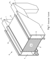
- Fig. 1 first shows schematically the structure of a known corner connection 1 in a perspective view.
- the cavity between the insulating webs D is filled with insulation E.
- the outer shell B has a hollow chamber F and the inner shell C has a hollow chamber G.
- corner brackets H 1 and H 2 are used, the free legs of which on the one hand go into the hollow chambers F and G of the horizontal frame profile A and on the other hand from above into the vertical hollow chambers of the vertical frame profile, not shown, and glued there.
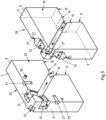
- a corner connection 1 according to the invention is shown in a first exemplary embodiment of a corner angle 2 in a perspective view from two sides.
- the corner bracket 2 is arranged within a first and a second frame profile 3, 4, which are connected to one another via the corner bracket 2.
- only a single corner angle per corner connection is shown in the figures in order to obtain a better overview.
- pairs of corner angles are regularly inserted into the hollow chambers of both the outer shell and the inner shell of the frame profiles and glued there.
- the frame profiles 3, 4 are therefore only indicated by dashed lines for the sake of clarity. In addition, for the sake of clarity, no adhesive is shown.
- the corner angle 2 comprises two corner angle halves 5, 6, which are preferably made of a cast material.
- the corner angle halves 5, 6 are arranged next to each other so that together they form the wider corner angle 2.
- the corner angle halves 5, 6 are designed to be mirror-symmetrical, which has an advantageous effect on the flexibility during installation of the corner angle 2.
- the corner bracket 2 has adhesive spaces 12, 13, 14, 15 on its outer sides 8, 9, 10, 11 facing the inner surfaces of the frame profiles 3, 4.
- the adhesive spaces 12, 13, 14, 15 are suitable for receiving an adhesive not shown in the figures.
- the corner angle halves 5, 6 are attached via the adhesive spaces 12, 13, 14, 15 Corner bracket 2 is connected to the frame profiles 3, 4 when filled with adhesive.
- a first adhesive space 12 on the external, horizontally extending outside 8 a second adhesive space 13 on the external, vertically extending outside 9, a third adhesive space 14 on the horizontally extending internal outside 10 and a fourth adhesive space 15 on the vertically extending internal outside 11 intended.
- the adhesive can be introduced into the corner connection 1 via an adhesive inlet 16 formed on the first frame profile 3.
- the adhesive inlet 16 is arranged above the first adhesive space 12.
- the first adhesive space 12 forms an adhesive inlet opening 17.
- the adhesive inlet 16 and the adhesive inlet opening 17 together form a passage during the filling process through which adhesive can be introduced into the interior of the corner bracket 2.
- a channel inlet opening is formed on the first adhesive space 12, from which an adhesive-carrying channel 18 extends into the interior of the corner bracket 2.
- the adhesive inlet 16 and the channel inlet opening are advantageously not arranged coaxially, so that the tip of a static mixer that is usually used for adhesive injection cannot enter the adhesive-carrying channel 18. This could otherwise lead to the first adhesive space 12 not being filled or only being filled insufficiently.
- Glue can be transported from the adhesive inlet opening 17 to the individual gluing spaces 12, 13, 14, 15 via the adhesive-carrying channel 18.
- the first and second adhesive spaces 12, 13 are connected to one another via the adhesive-carrying channel 18.
- the adhesive-carrying channel 18 runs diagonally along an angle bisector of the corner bracket 2 on its outer surfaces 19, 20.
- This section of the adhesive-carrying channel 18 is designed as an open channel so that it fulfills the function of an adhesive space when filled.
- the section runs along the miter forming Abutting edges of frame profiles 3 and 4, which are securely glued over this channel section.
- Glue can be transported from the third and fourth gluing spaces 14, 15 to a fifth and sixth gluing spaces 21, 22 via the diagonally extending section of the adhesive-carrying channel 18.
- the fifth and sixth adhesive spaces 21, 22 are arranged in the corner regions of the corner bracket 2 and are last filled with adhesive.
- an adhesive outlet 23 is arranged in the first frame profile 3.
- the sixth adhesive space 22 takes over the adhesive outlet opening 24 and forms a passage with the adhesive outlet 23 in the frame profile 3 in the unfilled state or during adhesive injection, through which adhesive can flow to the outside.
- the adhesive-carrying channel 18 runs through the corner angle 2 in such a way that the sixth adhesive space 22 is filled last, so that adhesive can only emerge from the adhesive outlet 23 when all of the adhesive spaces 12, 13, 14, 15, 21, 22 are filled with adhesive .
- the escape of adhesive is a reliable signal for the processor to stop further supply of adhesive.
- the corner angle 2 includes the corner angle halves 5, 6, each of which has a mutually assigned inner surface 25, 26, as is clear Fig. 3 emerges.
- the adhesive-carrying channel 18 on the outer surfaces 19, 20 is also formed in sections by the channel-shaped recesses provided in the inner surfaces 25, 26.
- the channel-shaped recesses have a semicircular cross section both on the outer surfaces 19, 20 and on the inner surfaces 25, 26. In the area of the inner surfaces 25, 26 they together form a substantially circular channel.
- Two recesses 27 are formed on the inner surfaces 25, 26 of the corner angle halves 5, 6, two of which each form a nail hole 28.
- a nail not shown here such as a hollow nail.
- the spreading has a positive effect on the open section of the adhesive-carrying channel 18 formed on the outer surfaces 19, 20.
- Spreading also ensures that the corner angle halves 5, 6 rest firmly on the inner sides of the frame profiles 3, 4, so that the adhesive cannot flow over the edges of the adhesive-carrying channel 18 when the corner connection 1 is filled.
- Fig. 3 is the corner angle 2 formed from the corner angle halves 5, 6 Fig. 2A shown in a perspective view in an exploded view.
- the flow direction of the adhesive during adhesive injection is shown schematically with arrows. From this illustration it can be clearly seen that the adhesive can flow from the first adhesive space 12 via the adhesive-carrying channel 18 to the second adhesive space 13.
- This section is designed in the shape of a circular arc.
- a section of the adhesive-carrying channel 18 formed on the inner surfaces 25, 26 extends diagonally from the circular arc-shaped section to the third and fourth adhesive spaces 14, 15.
- the adhesive is applied from the third and fourth adhesive spaces 14, 15 to the outer surfaces 19 , 20 of the corner angle halves 5, 6 extending sections of the adhesive-carrying channel 18.
- the adhesive reaches the fifth and sixth adhesive spaces 21, 22 via the sections of the adhesive-carrying channel 18 running on the outer surfaces 19, 20, from where it reaches the adhesive outlet 23.
- a depression 29 and a nose 30 are formed on the inner surfaces 25, 26 of the corner brackets 5, 6. When assembled, these interlock and prevent both parts from moving.
- the corner angle halves 5, 6 are each constructed in mirror symmetry.
- the plane of symmetry runs through an angle bisector of the corner connection 1, which in this case also corresponds to the miter of the frame.
- the adhesive-carrying channel 18 is formed in sections by channel-shaped recesses provided on the inner surfaces 25, 26.
- the recesses on the inner surfaces 25, 26 have a substantially semicircular cross section and together form a substantially circular channel section.
- the channel-shaped recess has a wall 31 on one inner surface on both sides of the channel-shaped recess.
- a recess 32 corresponding to the wall is formed on both sides of the channel-shaped recess. When assembled, the wall 31 engages in the recess 32.
- the corner angle halves 5, 6 spread apart.
- the expansion creates a gap 33 between the two corner angle halves 5, 6.
- the wall 31 arranged in the recess 32 can prevent or at least reduce this effect.
- the lateral distance 34 between the recess 32 and the wall 31 should be chosen to be significantly smaller than the gap 33 between the corner angle halves 5, 6.
- the gap 33 between the corner angle halves 5 and 6 can for example, 0.6 mm and the distance 34 between the recess 32 and the wall 31 is 0.2 mm.
- Fig. 5 is corner connection 1 Fig. 2A shown in a glue-filled state. It can be seen that the corner bracket 2 is glued in several places to the frame profiles 3, 4, which are only indicated.
- FIG. 6A and 6B a second exemplary embodiment of a corner connection 1 'according to the invention is shown.
- the main difference from the first exemplary embodiment is a backing 35 that changes the width of the corner angle 2 '.
- an extruded profile can be used as the backing 35.
- the backing 35 can be produced in several sizes with little effort and the width of the corner angle 2' can be modified by attaching it to a corner angle half 6'.
- the two elements can be connected, for example, via a dovetail connection.
- a first adhesive space 12' is formed on an outer surface 36 of the backing 35.
- the adhesive-carrying channel 18 has a section leading to the first adhesive space 12'.
- a second adhesive space 13' opposite the first adhesive space 12' is formed on the corner angle half 5' without backing 35.
- the adhesive-carrying channel 18 also has a section leading to the second adhesive space 13'.
- the second adhesive space 13' is designed to be larger than the first adhesive space 12', so that the first adhesive space 12' is completely filled with adhesive more quickly during the filling process than the second adhesive space 13'.
- the adhesive is fed into the second adhesive space 13' in an upper region of the second adhesive space 13'.
- Two sections of the adhesive-carrying channel 18 lead from the second adhesive space 13' in the direction of an adhesive outlet opening 24, with only one of them having a corresponding adhesive outlet 23 in this exemplary embodiment.
- These two sections are designed as a final section 37 and therefore have a smaller one Diameter than the other sections of the adhesive-carrying channel 18. Due to the smaller diameter, the adhesive can only flow comparatively slowly through the end section 37.
- the end sections 37 of the adhesive-carrying channel 18 starting from the second adhesive space 13' begin in a lower region of the second adhesive space 13', which is last filled with adhesive during the filling process. This structure ensures that during the filling process adhesive is only transported to the adhesive outlet 23 when the first and second adhesive spaces 12', 13' are completely filled with adhesive.
- the first and second adhesive spaces 12', 13' are preferably arranged behind the miter area of the profile frame, so that the abutting edges that meet there are securely glued.
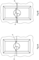
- the corner connection 1 ' is shown in a side view.
- the adhesive-carrying channel 18 and the nail holes 28 are shown in dashed lines.
- the flow direction of the adhesive marked with arrows can be easily understood during the filling process.
- the adhesive is introduced into the corner connection 1' via an adhesive inlet 16 formed on the frame profile 3.
- the adhesive-carrying channel 18 is connected directly to the adhesive inlet 16. From there, the adhesive-carrying channel 18 leads to the first and second adhesive spaces 12', 13'. Due to the smaller volume of the first adhesive space 12', it is filled more quickly than the second adhesive space 13'.
- the adhesive is introduced into the second adhesive space 13' at a point that is maximally distant from the point at which the adhesive flows out, it is ensured that during the bonding process adhesive only flows out of the second adhesive space 13' when it essentially flows out is completely filled with glue. From the second adhesive space 13′, the adhesive is transported via the adhesive-carrying channel 18 to the adhesive outlet 23. This section is designed as a final section 37.
- FIGS 8A and 8B show the corner connection 1' Figures 6A and 6B in a state filled with glue. It can be seen that the corner bracket 2' is largely glued to the frame profiles 3, 4 via the first and second adhesive spaces 12', 13'.
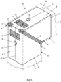
- Fig. 9 is finally a corner angle half 6 'of the corner angle 2' Fig. 6A shown in perspective view. It can be seen that a sealing tape 38 is arranged on the inner surface 26, which in the assembled state is arranged between the corner angle halves 5 ', 6'.
- the sealing tape 38 has recesses in the area of the channel-shaped recesses, depressions 29, lugs 30 and the nail holes 28 forming recesses 27 provided on the inner surfaces 25, 26.
- the corner bracket 2 ' is also nailed and spread, as explained in detail in the context of the first exemplary embodiment.
- the resulting gap 33 is filled with the help of the sealing tape 38.
- This has the contour of the inner surfaces 25, 26 of the corner angle halves 5 ', 6'. It is glued to the inner surfaces 25, 26 of the corner angle halves 5', 6' and works like a double-sided adhesive tape.
- the sealing tape 38 has an elastic foam in the middle and two adhesive surfaces on the outside.
- the sealing tape 38 is so thick that the total width of the corner bracket 2 'with the sealing tape 38 is excessive compared to the cavity formed in the frame.
- the corner angle halves 5', 6' must be pressed together in order to be able to insert the corner angle 2' into the frame profiles 3, 4.
- sealing tape 38 expands, whereby the corner bracket 2 'is spread open and presses against the frame profiles 3, 4 from the inside.
- the sealing tape 38 delimits the internal adhesive-carrying channel 18 with its recesses, so that uncontrolled running of the adhesive into the corner angle 2 'is avoided and the consumption of adhesive is also reduced.
- a correspondingly designed sealing tape can also be used in the first exemplary embodiment, even if not shown.
- the dimensions of the corner angles used can be designed differently. While the cross section of the corner angles is tailored to the internal dimensions of the frame profiles to be connected, the leg length can vary. It depends, for example, on the size of the frame and the expected loads for the respective application.
Abstract
Dargestellt und beschrieben ist eine Eckverbindung (1, 1') eines Rahmens aus Metallprofilen, insbesondere aus Aluminiumprofilen, mit einem ersten und einem zweiten, jeweils wenigstens eine Hohlkammer aufweisenden und über einen Eckwinkel (2, 2') miteinander verbundenen Rahmenprofil (3, 4), wobei jeder Eckwinkel (2, 2') innerhalb der jeweils eine Gehrung aufweisenden Enden der Rahmenprofile (3, 4) angeordnet ist, wobei das erste Rahmenprofil (3) einen Klebstoffeinlass (16) aufweist, wobei der Eckwinkel (2, 2') eine an einer Außenseite (8) des Eckwinkels (2, 2') ausgebildete zum Klebstoffeinlass (16) korrespondierende Klebstoffeintrittsöffnung (17) aufweist, wobei der Eckwinkel (2, 2') an wenigstens einer Außenseite wenigstens einen mit Klebstoff gefüllten Kleberaum (12, 13, 14, 15, 21, 22, 12', 13') aufweist, wobei der Eckwinkel (2, 2') über den wenigstens einen Kleberaum (12, 13, 14, 15, 21, 22, 12', 13') mit dem ersten und dem zweiten Rahmenprofil (3, 4) verbunden ist, wobei der Eckwinkel (2, 2') einen klebstoffführenden Kanal (18) aufweist und wobei der klebstoffführende Kanal (18) von der Klebstoffeintrittsöffnung (17) zu dem wenigstens einen Kleberaum (12, 13, 14, 15, 21, 22, 12', 13') verläuft. Um eine sichere Klebverbindung zwischen Eckwinkel (2, 2') und Rahmenprofilen (3, 4) sicherzustellen und zum Erreichen einer möglichst einfachen und kostengünstigen Lösung weisen das erste und/oder das zweite Rahmenprofil (3) wenigstens einen Klebstoffauslass (23) und der Eckwinkel (2, 2') wenigstens eine zu dem Klebstoffauslass (23) korrespondierende, mit dem klebstoffführenden Kanal (18) verbundene Klebstoffaustrittsöffnung (24) auf, wobei der klebstoffführende Kanal (18) so durch den Eckwinkel (2, 2') verläuft, so dass bei Befüllung des Eckwinkels (2, 2') mit Klebstoff erst Klebstoff aus dem wenigstens einen Klebstoffauslass (23) quillt, wenn alle Kleberäume (12, 13, 14, 15, 21, 22, 12', 13') im Wesentlichen vollständig mit Klebstoff befüllt sind. Ferner ist ein entsprechendes Verfahren beansprucht.Shown and described is a corner connection (1, 1') of a frame made of metal profiles, in particular aluminum profiles, with a first and a second frame profile (3, 4), each having at least one hollow chamber and connected to one another via a corner bracket (2, 2'). ), each corner angle (2, 2') being arranged within the mitered ends of the frame profiles (3, 4), the first frame profile (3) having an adhesive inlet (16), the corner angle (2, 2' ) has an adhesive inlet opening (17) formed on an outside (8) of the corner angle (2, 2') corresponding to the adhesive inlet (16), the corner angle (2, 2') having at least one adhesive space (12) filled with adhesive on at least one outside , 13, 14, 15, 21, 22, 12 ', 13'), the corner bracket (2, 2') extending over the at least one adhesive space (12, 13, 14, 15, 21, 22, 12', 13 ') is connected to the first and second frame profiles (3, 4), the corner bracket (2, 2') having an adhesive-carrying channel (18) and the adhesive-carrying channel (18) extending from the adhesive inlet opening (17) to the at least an adhesive space (12, 13, 14, 15, 21, 22, 12', 13'). In order to ensure a secure adhesive connection between corner angles (2, 2') and frame profiles (3, 4) and to achieve the simplest and most cost-effective solution possible, the first and/or the second frame profile (3) have at least one adhesive outlet (23) and the corner angle (2, 2') has at least one adhesive outlet opening (24) corresponding to the adhesive outlet (23) and connected to the adhesive-carrying channel (18), the adhesive-carrying channel (18) running through the corner angle (2, 2'), so that when the corner bracket (2, 2') is filled with adhesive, adhesive only oozes out of the at least one adhesive outlet (23) when all adhesive spaces (12, 13, 14, 15, 21, 22, 12', 13') are essentially complete are filled with adhesive. A corresponding method is also claimed.
Description
Die Erfindung betrifft eine Eckverbindung eines Rahmens aus Metallprofilen, insbesondere aus Aluminiumprofilen, vorzugsweise eines Fensters oder einer Tür, mit einem ersten und einem zweiten, jeweils wenigstens eine Hohlkammer aufweisenden und über einen Eckwinkel miteinander verbundenen Rahmenprofil, wobei jeder Eckwinkel innerhalb der jeweils eine Gehrung aufweisenden Enden der Rahmenprofile angeordnet ist, wobei das erste Rahmenprofil einen Klebstoffeinlass aufweist, wobei der Eckwinkel eine an einer Außenseite des Eckwinkels ausgebildete zum Klebstoffeinlass korrespondierende Klebstoffeintrittsöffnung aufweist, wobei der Eckwinkel an wenigstens einer Außenseite wenigstens einen mit Klebstoff gefüllten Kleberaum aufweist, wobei der Eckwinkel über den wenigstens einen Kleberaum mit dem ersten und dem zweiten Rahmenprofil verbunden ist, wobei der Eckwinkel einen klebstoffführenden Kanal aufweist und wobei der klebstoffführende Kanal von der Klebstoffeintrittsöffnung zu dem wenigstens einen Kleberaum verläuft.The invention relates to a corner connection of a frame made of metal profiles, in particular aluminum profiles, preferably a window or a door, with a first and a second frame profile, each having at least one hollow chamber and connected to one another via a corner angle, each corner angle within the each having a miter Ends of the frame profiles are arranged, the first frame profile having an adhesive inlet, the corner angle having an adhesive inlet opening formed on an outer side of the corner angle and corresponding to the adhesive inlet, the corner angle having at least one adhesive space filled with adhesive on at least one outer side, the corner angle over the at least one adhesive space is connected to the first and the second frame profile, wherein the corner angle has an adhesive-carrying channel and wherein the adhesive-carrying channel runs from the adhesive inlet opening to the at least one adhesive space.
Ferner betrifft die Erfindung ein Verfahren zur Herstellung einer Eckverbindung, wobei Klebstoff in einen Eckwinkel über einen Klebstoffeinlass zugeführt wird.The invention further relates to a method for producing a corner connection, wherein adhesive is supplied into a corner angle via an adhesive inlet.
Eckverbindungen der genannten Art werden beispielsweise zum Bau von Fensterrahmen, Türrahmen oder Fassadenrahmen eingesetzt. Die Rahmenprofile derartiger Rahmen sind meist gerade, beispielsweise stranggepresste und wenigstens eine Hohlkammer aufweisende Rahmen, die an den Ecken des Rahmens aufeinanderstoßen. Dort werden die Rahmenprofile mittels Eckwinkeln verbunden, die jeweils zum Teil in die Hohlräume der beiden miteinander zu verbindenden Rahmenprofile eingesteckt sind. Um eine sichere und dichte Verbindung in den Ecken der Rahmen sicherzustellen, werden die Rahmenprofile mit den Eckwinkeln verklebt. Hierzu wird Klebstoff in die Eckwinkel injiziert und durch einen klebstoffführenden Kanal zu Kleberäumen geleitet. Die Kleberäume eignen sich zur Aufnahme einer bestimmten Klebstoffmenge und stellen im befüllten Zustand eine Klebeverbindung zwischen Eckwinkel und Rahmenprofil her.Corner connections of the type mentioned are used, for example, for the construction of window frames, door frames or facade frames. The frame profiles of such frames are usually straight, for example extruded frames with at least one hollow chamber, which abut one another at the corners of the frame. There the frame profiles are connected using corner brackets, some of which are inserted into the cavities of the two frame profiles to be connected to one another. To ensure a secure and tight connection in the corners of the frame, the frame profiles are glued to the corner brackets. To do this, glue is injected into the corner angles and passed through an adhesive guide Channel routed to gluing rooms. The adhesive spaces are suitable for holding a certain amount of adhesive and, when filled, create an adhesive connection between the corner angle and the frame profile.
Eine bekannte Eckverbindung ist in der deutschen Patentanmeldung
Darüber hinaus sind aus der Praxis Eckverbindungen bekannt, bei denen die Eckverbinderprofile als metallene Eckwinkel ausgebildet sind.In addition, corner connections are known from practice in which the corner connector profiles are designed as metal corner brackets.
Die zu injizierende Klebstoffmenge wird bei den bekannten Eckverbindungen im Fertigungskatalog abhängig vom verwendeten Eckwinkel angegeben. Nachteilig an den bekannten Eckprofilen ist, dass es keine Möglichkeit gibt, von außen zu bewerten, ob ausreichend Klebstoff verwendet wurde. Dies birgt die Gefahr, dass zu wenig Klebstoff in die Eckverbindung eingebracht wurde und infolgedessen der Eckwinkel und die Enden der Rahmenprofile nicht sicher miteinander verklebt worden sind.For the known corner connections, the amount of adhesive to be injected is specified in the production catalog depending on the corner angle used. The disadvantage of the known corner profiles is that there is no way to assess from the outside whether sufficient adhesive has been used. This poses the risk that too little adhesive has been applied to the corner connection and as a result the corner angle and the ends of the frame profiles have not been securely glued together.
Der vorliegenden Erfindung liegt daher die Aufgabe zugrunde, die eingangs genannte und zuvor näher beschriebene Eckverbindung sowie das ebenfalls eingangs genannte Verfahren zur Herstellung einer solchen Eckverbindung derart auszugestalten und weiterzubilden, dass eine sichere Klebverbindung zwischen Eckwinkel und Rahmenprofilen sichergestellt werden kann. Hierbei soll eine möglichst einfache und kostengünstige Lösung angestrebt werden. Darüber hinaus ist erwünscht, das Verfahren zur Herstellung einer solchen Eckverbindung einfacher zu gestalten.The present invention is therefore based on the object of designing and developing the corner connection mentioned at the beginning and previously described in more detail as well as the method for producing such a corner connection also mentioned at the beginning in such a way that a secure adhesive connection between the corner angle and Frame profiles can be ensured. The aim is to create a solution that is as simple and cost-effective as possible. In addition, it is desirable to make the process for producing such a corner connection simpler.
Diese Aufgabe ist bei einer Eckverbindung nach dem Oberbegriff von Anspruch 1 dadurch gelöst, dass das erste und/oder das zweite Rahmenprofil wenigstens einen Klebstoffauslass aufweisen und der Eckwinkel wenigstens eine zu dem Klebstoffauslass korrespondierende, mit dem klebstoffführenden Kanal verbundene Klebstoffaustrittsöffnung aufweist, wobei der klebstoffführende Kanal so durch den Eckwinkel verläuft, dass bei Befüllung des Eckwinkels mit Klebstoff erst Klebstoff aus dem wenigstens einen Klebstoffauslass quillt, wenn alle Kleberäume im Wesentlichen vollständig mit Klebstoff befüllt sind.This object is achieved in a corner connection according to the preamble of
Ferner ist die vorgenannte Aufgabe bei einem Verfahren gemäß dem Oberbegriff von Anspruch 15 dadurch gelöst, dass die Klebstoffzufuhr beendet wird, wenn an einem Klebstoffauslass Klebstoff austritt, wobei vorzugsweise vor Einbringung des Klebstoffs in den Eckwinkel wenigstens ein Nagel, insbesondere wenigstens zwei Nägel, in ein an dem Eckwinkel dafür vorgesehenen Nagelloch, vorzugsweise in zwei an dem Eckwinkel dafür vorgesehenen Nagellöcher eingebracht wird/werden.Furthermore, the aforementioned object is achieved in a method according to the preamble of
Die Erfindung hat erkannt, dass die Fertigung von Eckverbindungen sicherer gestaltet werden kann, wenn der Verarbeitende ein Signal (Feedback) erhält, wenn genügend Klebstoff in den Eckwinkel eingebracht worden ist. Hierdurch entfällt für den Verarbeitenden auch der Schritt des Nachschlagens der zu injizierenden Klebstoffmenge. Infolgedessen wird eine Fehlerquelle in der Herstellung der Eckverbindung zuverlässig vermieden.The invention has recognized that the production of corner connections can be made safer if the processor receives a signal (feedback) when enough adhesive has been introduced into the corner angle. This also eliminates the need for the processor to look up the amount of adhesive to be injected. As a result, a source of error in the production of the corner connection is reliably avoided.
Das Signal für den Verarbeitenden wird dadurch erzeugt, dass Klebstoff aus einem dafür vorgesehenen Klebstoffauslass austritt (Feedback-Anzeige). Sobald der Verarbeitende sieht, dass Klebstoff austritt, weiß er, dass alle Kleberäume ausreichend mit Klebstoff befüllt sind, um eine sichere Klebverbindung zwischen Eckwinkel und Rahmenprofilen sicherzustellen. Zu diesem Zeitpunkt kann der Verarbeitende die Zufuhr von Klebstoff beenden. So wird sichergestellt, dass niemals zu wenig Klebstoff in den Eckwinkel eingebracht wird.The signal for the processor is generated by adhesive emerging from a designated adhesive outlet (feedback display). As soon as the processor sees that adhesive is coming out, he knows that all adhesive spaces are sufficiently filled with adhesive to ensure a secure adhesive connection between Ensure corner angles and frame profiles. At this point, the processor can stop supplying adhesive. This ensures that too little adhesive is never applied to the corner bracket.
Damit nicht bereits Klebstoff aus dem Klebstoffauslass austritt, wenn noch nicht alle Kleberäume ausreichend mit Klebstoff gefüllt sind, ist es erforderlich, dass der klebstoffführende Kanal derart durch den Eckwinkel verläuft, dass bei Befüllung der Eckverbindung mit Klebstoff erst Klebstoff aus dem wenigstens einen Klebstoffauslass quillt, wenn alle Kleberäume im Wesentlichen vollständig mit Klebstoff befüllt sind. Der Verlauf des klebstoffführenden Kanals muss also so ausgebildet sein, dass erst alle Kleberäume mit Klebstoff versorgt werden, bevor der Klebstoff zur Klebstoffaustrittsöffnung gelangen kann.To ensure that adhesive does not escape from the adhesive outlet when not all adhesive spaces are sufficiently filled with adhesive, it is necessary that the adhesive-carrying channel runs through the corner angle in such a way that when the corner connection is filled with adhesive, adhesive only oozes out of the at least one adhesive outlet, when all gluing spaces are essentially completely filled with adhesive. The course of the adhesive-carrying channel must therefore be designed in such a way that all adhesive spaces are supplied with adhesive before the adhesive can reach the adhesive outlet opening.
Zur Realisierung dieser Voraussetzung gibt es unterschiedliche Möglichkeiten. Beispielsweise kann der klebstoffführende Kanal die Klebstoffeintrittsöffnung über alle Kleberäume mit der Klebstoffaustrittsöffnung verbinden. In diesem Fall wird der Klebstoff von der Klebstoffeintrittsöffnung zu den in einer während des Verklebungsvorgangs sich einstellenden Klebstoffflussrichtung nacheinander angeordneten Kleberäumen geleitet, wo diese erst befüllt werden, bevor der Klebstoff zur Klebstoffaustrittsöffnung geleitet werden kann. Alternativ können auch mehrere Kleberäume gleichzeitig befüllt werden, wobei der klebstoffführende Kanal so ausgebildet ist, dass er eine Verbindung von dem zuletzt fertig befüllten Kleberaum zu der Klebstoffaustrittsöffnung aufweist.There are different options for realizing this requirement. For example, the adhesive-carrying channel can connect the adhesive inlet opening to the adhesive outlet opening via all adhesive spaces. In this case, the adhesive is guided from the adhesive inlet opening to the adhesive spaces arranged one after the other in an adhesive flow direction that occurs during the bonding process, where these are first filled before the adhesive can be directed to the adhesive outlet opening. Alternatively, several adhesive spaces can be filled at the same time, with the adhesive-carrying channel being designed such that it has a connection from the last completely filled adhesive space to the adhesive outlet opening.
Alternativ oder zusätzlich kann der klebstoffführende Kanal einen mit der wenigstens einen Klebstoffaustrittsöffnung verbundenen Abschlussabschnitt aufweisen, wobei der Abschlussabschnitt einen kleineren Durchmesser als der übrige klebstoffführende Kanal aufweist. Der Durchmesser muss so klein gewählt werden, dass der Klebstoff verhältnismäßig langsam durch den Abschlussabschnitt fließen kann, so dass sichergestellt ist, dass der Klebstoff die Klebstoffaustrittsöffnung erst erreicht, wenn die Kleberäume mit Klebstoff befüllt sind.Alternatively or additionally, the adhesive-carrying channel can have a termination section connected to the at least one adhesive outlet opening, the closure section having a smaller diameter than the remaining adhesive-carrying channel. The diameter must be chosen so small that the adhesive can flow relatively slowly through the end section, so that it is ensured that the adhesive only reaches the adhesive outlet opening when the adhesive spaces are filled with adhesive.
Bei einer besonders bevorzugen weiteren Ausgestaltung der Erfindung umfasst der Eckwinkel zwei im Wesentlichen parallel angeordnete, vorzugsweise aus einem Gussmaterial hergestellte, Eckwinkelhälften, wobei die Eckwinkelhälften jeweils eine zueinander zugeordnete Innenfläche aufweisen, wobei insbesondere der klebstoffführende Kanal zumindest abschnittsweise durch wenigstens auf einer der Innenflächen vorgesehenen kanalförmigen Ausnehmung gebildet ist, wobei vorzugsweise auf beiden Innenflächen zueinander korrespondierende kanalförmige Ausnehmungen gebildet sind, die gemeinsam einen im Querschnitt geschlossenen klebstoffführenden Kanal bilden.In a particularly preferred further embodiment of the invention, the corner angle comprises two essentially parallel corner angle halves, preferably made from a cast material, the corner angle halves each having an inner surface assigned to one another, in particular the adhesive-carrying channel at least in sections through channel-shaped ones provided on at least one of the inner surfaces Recess is formed, preferably on both inner surfaces corresponding channel-shaped recesses are formed, which together form an adhesive-carrying channel with a closed cross section.
Wenn hier und im Folgenden von ,Eckwinkelhälften` die Rede ist, sollen darunter nicht nur exakt gestaltete hälftige Formkörper zu verstehen sein, sondern alle zweiteilig aufgebauten Eckwinkel mit einer gemeinsamen Fügefläche, welche nach dem Zusammenbau bzw. der Montage der Eckverbindungen einen gemeinsamen Eckwinkel bilden. Bevorzugt werden die Eckwinkelhälften als Gussteile hergestellt.When we talk about “corner angle halves” here and in the following, this should not only mean precisely designed half-shaped bodies, but also all corner angles constructed in two parts with a common joining surface, which form a common corner angle after the corner connections have been assembled or assembled. The corner angle halves are preferably manufactured as cast parts.
Die Fertigung des Eckwinkels aus zwei Eckwinkelhälften bietet einige fertigungstechnische Vorteile. Vorteilhafterweise werden die Eckwinkelhälften so ausgelegt, dass ein seitliches Spiel zwischen den Innenwandungen der Hohlkammern der Rahmenprofile und den Eckwinkelhälften vorhanden ist. So können die je aus zwei Eckwinkelhälften zusammengesetzten Eckwinkel leicht in die Hohlkammern der zu verbindenden Rahmenprofile eingeschoben werden. Anschließend können die Eckwinkelhälften auseinander gespreizt werden, so dass das Spiel zwischen den Innenwandungen der Rahmenprofile und den Eckwinkelhälften im Wesentlichen verschwindet. Ein Spiel von 0,4 bis 0,8 mm, bevorzugt von 0,5 bis 0,7 mm und besonders bevorzugt von 0,6 mm hat sich als besonders zweckmäßig erwiesen. Zudem lassen sich deutlich einfacher offene Kanäle auf der Oberfläche eines Gussteils herstellen als Kanäle, die im Inneren des Gussteils angeordnet sind. Durch das Zusammenfügen zweier Gussteile können im Inneren jedes Eckwinkels verlaufende Kanäle im mit geringem Aufwand hergestellt werden.Manufacturing the corner bracket from two corner bracket halves offers several manufacturing advantages. Advantageously, the corner angle halves are designed so that there is lateral play between the inner walls of the hollow chambers of the frame profiles and the corner angle halves. This means that the corner angles, each composed of two corner angle halves, can be easily inserted into the hollow chambers of the frame profiles to be connected. The corner angle halves can then be spread apart so that the play between the inner walls of the frame profiles and the corner angle halves essentially disappears. A clearance of 0.4 to 0.8 mm, preferably 0.5 to 0.7 mm and particularly preferably 0.6 mm has proven to be particularly useful. In addition, it is much easier to produce open channels on the surface of a casting than channels that are arranged inside the casting. By joining two cast parts together, channels running inside each corner angle can be produced with little effort.
Eine weitere bevorzugte Lehre der Erfindung sieht vor, dass an der kanalförmigen Ausnehmung an der einen Innenfläche eine Wandung auf beiden Seiten der kanalförmigen Ausnehmung ausgebildet ist und an der anderen Innenfläche eine zu der Wandung korrespondierende Aussparung an den beiden Seiten der kanalförmigen Ausnehmung ausgebildet ist. Durch die voranstehend beschriebene zweiteilige Ausbildung jedes Eckwinkels und durch die Spreizung der Eckwinkelhälften zur Befestigung des Eckwinkels entsteht ein Spalt zwischen den Innenflächen der E ckwinkelhälften.A further preferred teaching of the invention provides that on the channel-shaped recess on one inner surface a wall is formed on both sides of the channel-shaped recess and on the other inner surface a recess corresponding to the wall is formed on both sides of the channel-shaped recess. Due to the above-described two-part design of each corner angle and the spreading of the corner angle halves to fasten the corner angle, a gap is created between the inner surfaces of the corner angle halves.
Die auf den Innenflächen vorgesehenen kanalförmigen Ausnehmungen, die gemeinsam einen geschlossenen Kanalabschnitt bilden, werden durch die Spreizung auseinander getrieben, so dass bei dem Verklebungsvorgang Klebstoff aus den kanalförmigen Ausnehmungen herauslaufen kann. Dies ist unerwünscht. Um den Spalt, durch den Klebstoff während des Verklebens entweichen könnte, zu reduzieren, können die kanalförmigen Ausnehmungen auf der einen Innenfläche mit einer Wandung und auf der anderen Innenfläche mit einer Ausnehmung ausgestattet werden. Diese sollten so dimensioniert sein, dass sich auch nach dem Spreizen der Eckwinkelhälften ein Teil der Wandung in der Ausnehmung befindet, so dass Klebstoff nicht ohne weiteres seitlich aus den kanalförmigen Ausnehmungen entweichen kann. Es ist allerdings zu beachten, dass weiterhin ein seitlicher Spalt zwischen der dem klebstoffführenden Kanal abgewandten Seite der Wandung und der Ausnehmung existiert. Dieser sollte möglichst klein bemessen sein, so dass der Austritt von Klebstoff aus dem klebstoffführenden Kanal während des Verklebungsvorgangs möglichst vermieden oder zumindest so stark wie möglich reduziert wird.The channel-shaped recesses provided on the inner surfaces, which together form a closed channel section, are driven apart by the expansion, so that adhesive can run out of the channel-shaped recesses during the bonding process. This is undesirable. In order to reduce the gap through which adhesive could escape during bonding, the channel-shaped recesses can be equipped with a wall on one inner surface and a recess on the other inner surface. These should be dimensioned so that even after the corner angle halves have been spread, part of the wall is in the recess so that adhesive cannot easily escape laterally from the channel-shaped recesses. However, it should be noted that there is still a lateral gap between the side of the wall facing away from the adhesive-carrying channel and the recess. This should be as small as possible so that the escape of adhesive from the adhesive-carrying channel during the bonding process is avoided as much as possible or at least reduced as much as possible.
Bei einer bevorzugten Ausgestaltung der Erfindung sind an den Innenflächen der Eckwinkelhälften jeweils eine Vertiefung und eine Nase ausgebildet, wobei die Nase an der einen Innenfläche in die Vertiefung der anderen Innenfläche greift. Die Nasen und die Vertiefungen dienen als Positionierungshilfe und erleichtern den Montageprozess.In a preferred embodiment of the invention, a recess and a nose are formed on the inner surfaces of the corner angle halves, the nose on one inner surface engaging in the recess on the other inner surface. The lugs and recesses serve as a positioning aid and make the assembly process easier.
Besonders bevorzugt ist an den Innenflächen wenigstens jeweils eine Ausnehmung, vorzugsweise sind jeweils wenigstens zwei Ausnehmungen ausgebildet, die gemeinsam ein Nagelloch bilden. In die Nagellöcher wird bei dem Zusammenbau der Eckverbindung ein Nagel, vorzugsweise ein Hohlnagel, eingetrieben. Der Radius der Nagellöcher und die Nagelgröße werden so gewählt, dass bei Einbringung der Nägel in die Nagellöcher die Eckwinkelhälften auseinander getrieben werden. Das Verhältnis sollte so gewählt werden, dass die Eckwinkelhälften nach Einbringung der Nägel mit ihren Außenflächen an den innenliegenden Flächen der Hohlkammern der Rahmenprofile anliegen. Durch die Einbringung der Nägel wird das seitliche Spiel, welches vorher zwischen den Eckwinkelhälften und den innenliegenden Flächen der Rahmenprofile vorhanden war, so stark reduziert, dass die Eckwinkelhälften fest in je einer Hohlkammer der Rahmenprofile sitzen. Die Nagellöcher sollten dabei so positioniert werden, dass sich eine möglichst gleichmäßige Spreizung des Eckwinkels ergibt. Aus diesem Grund ist es auch besonders vorteilhaft, wenigsten zwei Nagellöcher vorzusehen, die möglichst von unterschiedlichen Seiten bestückt werden können. Die Nagellöcher sollten einen ausreichenden Abstand zu den Kleberäumen aufweisen. Als zweckmäßig hat sich ein Abstand von 0,4 bis 0,8 mm, bevorzugt von 0,5 bis 0,7 mm und besonders bevorzugt von 0,6 mm herausgestellt. Besonders bevorzugt sind die Nagellöcher mit einer Fase versehen, um das Einbringen der Nägel zu vereinfachen.Particularly preferably, at least one recess is formed on the inner surfaces, preferably at least two recesses are formed, which together form a nail hole. A nail, preferably a hollow nail, is driven into the nail holes when assembling the corner connection. The radius of the nail holes and the nail size are chosen so that the corner angle halves are driven apart when the nails are inserted into the nail holes. The ratio should be chosen so that after the nails have been inserted, the outer surfaces of the corner angle halves rest against the inner surfaces of the hollow chambers of the frame profiles. By inserting the nails, the lateral play that previously existed between the corner angle halves and the inner surfaces of the frame profiles is reduced to such an extent that the corner angle halves sit firmly in a hollow chamber of the frame profiles. The nail holes should be positioned so that the spread of the corner angle is as even as possible. For this reason, it is particularly advantageous to provide at least two nail holes, which can be filled from different sides if possible. The nail holes should be at a sufficient distance from the gluing spaces. A distance of 0.4 to 0.8 mm, preferably 0.5 to 0.7 mm and particularly preferably 0.6 mm has proven to be expedient. The nail holes are particularly preferably provided with a chamfer in order to simplify the insertion of the nails.
Nach einer weiteren bevorzugten Lehre der Erfindung ist zwischen den Eckwinkelhälften ein Dichtband angeordnet. Vorzugsweise weist das Dichtband Aussparungen im Bereich der auf den Innenflächen vorgesehenen kanalförmigen Ausnehmungen, Vertiefungen, Nasen und die Nagellöcher bildenden Ausnehmungen auf. Wie bereits voranstehend erläutert, sind die Eckwinkelhälften bevorzugt so ausgelegt, dass ein seitliches Spiel zwischen den Eckwinkelhälften und den innenliegenden Wandungen der Rahmenprofile existiert. Der durch das Spiel entstehende Spalt wird mithilfe des Dichtbands aufgefüllt. Dieses hat vorteilhafterweise die Kontur der Innenflächen der Eckwinkelhälften. Es kann auf der gesamten Innenfläche einer Eckwinkelhälfte wie ein doppelseitiges Klebeband aufgebracht werden.According to a further preferred teaching of the invention, a sealing tape is arranged between the corner angle halves. The sealing tape preferably has recesses in the area of the channel-shaped recesses, depressions, lugs and recesses forming the nail holes provided on the inner surfaces. As already explained above, the corner angle halves are preferably designed so that there is lateral play between the corner angle halves and the inner walls of the frame profiles. The gap caused by the play is filled using the sealing tape. This advantageously has the contour of the inner surfaces of the corner angle halves. It can be on the The entire inner surface of a corner angle can be applied like double-sided adhesive tape.
Das Dichtband besteht aus einem elastischen Schaumstoff und zwei Klebflächen. Die Dicke ist in Abhängigkeit des Spaltes zu wählen. Beispielsweise hat sich eine Dicke des Dichtbands von 0,8 bis 1,2 mm, bevorzugt von 0,9 bis 1,1 mm und besonders bevorzugt von 1 mm als zweckmäßig erwiesen. Die Eckwinkelhälften, zwischen denen ein Dichtband angeordnet ist, sollten in der Breite ein Übermaß im Vergleich zu den Innenwandungen der Rahmenprofile aufweisen. Bei der Montage eines Eckwinkels werden die Eckwinkelhälften zusammengedrückt, um sie in die Hohlkammern der Rahmenprofile einschieben zu können. Wird der durch das Zusammendrücken entstehende Druck aufgehoben, dehnt sich das Dichtband aus, wodurch der Eckwinkel aufgespreizt wird, so dass die Außenflächen der Eckwinkelhälften gegen die Innenwandungen der Rahmenprofile drücken. Das Dichtband hilft, während des Verklebungsvorgangs ein unkontrolliertes Verlaufen des Klebstoffes in das Profil zu vermeiden oder zumindest zu reduzieren, so dass auch der Klebstoffverbrauch verringert wird.The sealing tape consists of elastic foam and two adhesive surfaces. The thickness must be chosen depending on the gap. For example, a sealing tape thickness of 0.8 to 1.2 mm, preferably 0.9 to 1.1 mm and particularly preferably 1 mm has proven to be expedient. The corner angle halves, between which a sealing tape is arranged, should have an excess width compared to the inner walls of the frame profiles. When assembling a corner bracket, the corner bracket halves are pressed together so that they can be inserted into the hollow chambers of the frame profiles. If the pressure caused by the compression is released, the sealing tape expands, causing the corner bracket to be spread open so that the outer surfaces of the corner bracket halves press against the inner walls of the frame profiles. The sealing tape helps to avoid or at least reduce uncontrolled running of the adhesive into the profile during the bonding process, so that adhesive consumption is also reduced.
Besonders bevorzugt verläuft der klebstoffführende Kanal zumindest abschnittsweise an einer Außenseite des Eckwinkels und ist als offener Kanal ausgebildet. Ein entsprechender Kanalabschnitt sorgt ebenfalls für eine Verklebung zwischen Eckwinkel und Rahmenprofil und erfüllt neben der Klebstoffführung auch die Funktion eines Kleberaums. Vorzugsweise verläuft der klebstoffführende Kanal zumindest abschnittsweise entlang der durch die Enden der Rahmenprofile gebildeten Gehrung, so dass eine sichere Verklebung der Rahmenprofile an der Gehrung sichergestellt ist.Particularly preferably, the adhesive-carrying channel runs at least in sections on an outside of the corner angle and is designed as an open channel. A corresponding channel section also ensures bonding between the corner angle and the frame profile and, in addition to guiding the adhesive, also serves as an adhesive space. The adhesive-carrying channel preferably runs at least in sections along the miter formed by the ends of the frame profiles, so that secure bonding of the frame profiles to the miter is ensured.
Vorteilhafterweise bildet ein erster Kleberaum die Klebstoffeintrittsöffnung, wobei in dem ersten Kleberaum eine Kanaleintrittsöffnung des klebstoffführenden Kanals angeordnet ist und wobei der Klebstoffeinlass und die Kanaleintrittsöffnung nicht koaxial angeordnet sind. Die an jedem Eckwinkel ausgebildete Klebstoffeintrittsöffnung und der am Rahmenprofil ausgebildete Klebstoffeinlass bilden im unbefüllten Zustand bzw. während des Befüllungsvorgangs einen Durchgang, durch den Klebstoff in das Innere des Eckwinkels fließen kann. Wird die Klebstoffeintrittsöffnung durch den ersten Kleberaum gebildet und ist der Klebstoffeinlass im Wesentlichen koaxial zu der Kanaleintrittsöffnung angeordnet, könnte ein üblicherweise zur Klebstoffinjektion verwendeter Statikmischer mit seiner Spitze in die Kanaleintrittsöffnung hineinragen. In diesem Fall würde der erste Kleberaum nicht oder nur ungenügend mit Klebstoff befüllt werden. Aus diesem Grund ist es zweckmäßig, den Klebstoffeinlass nicht koaxial zur Kanaleintrittsöffnung zu positionieren.A first adhesive space advantageously forms the adhesive inlet opening, a channel inlet opening of the adhesive-carrying channel being arranged in the first adhesive space and the adhesive inlet and the channel inlet opening not being arranged coaxially. The one formed at each corner angle When unfilled or during the filling process, the adhesive inlet opening and the adhesive inlet formed on the frame profile form a passage through which adhesive can flow into the interior of the corner bracket. If the adhesive inlet opening is formed by the first adhesive space and the adhesive inlet is arranged essentially coaxially with the channel inlet opening, a static mixer usually used for adhesive injection could protrude with its tip into the channel inlet opening. In this case, the first adhesive space would not be filled with adhesive or only insufficiently. For this reason, it is advisable not to position the adhesive inlet coaxially with the channel inlet opening.
Darüber hinaus hat es sich als zweckmäßig erwiesen, wenn der Eckwinkel eine die Breite des Eckwinkels modifizierende Hinterfütterung aufweist. Dies ermöglicht es, den Eckwinkel aufwandsarm an verschiedene Rahmenprofile unterschiedlicher Größe anzupassen. Die Hinterfütterung kann beispielsweise als kleinerer Winkel ausgebildet sein, der in gleicher Ausrichtung an einer Seite des Eckwinkels angebracht wird.In addition, it has proven to be expedient if the corner bracket has a backing that modifies the width of the corner bracket. This makes it possible to adapt the corner bracket to different frame profiles of different sizes with little effort. The backing can, for example, be designed as a smaller angle that is attached to one side of the corner angle in the same orientation.
Vorteilhafterweise ist auch an der Hinterfütterung wenigstens ein Kleberaum ausgebildet, der mit dem klebstoffführenden Kanal verbunden ist. Auf diese Weise kann auch die Hinterfütterung mit dem Rahmenprofil verklebt werden.Advantageously, at least one adhesive space is also formed on the backing, which is connected to the adhesive-carrying channel. In this way, the backing can also be glued to the frame profile.
Die Hinterfütterung und der Eckwinkel können dabei bevorzugt über eine Schwalbenschwanzverbindung formschlüssig miteinander verbindbar und/oder verbunden sein. Eine Schwalbenschwanzverbindung ermöglicht eine einfache Anbindung der Hinterfütterung, die bei Bedarf auch wieder gelöst werden kann. Zudem hat der Verarbeitende dadurch einen zusammengesteckten Eckwinkel, was bei der Montage eine leichtere Handhabung ermöglicht als zwei Einzelteile.The backing and the corner bracket can preferably be connected and/or connected to one another in a form-fitting manner via a dovetail connection. A dovetail connection allows for easy connection of the back lining, which can also be released again if necessary. In addition, the processor has a corner bracket that is put together, which makes assembly easier to handle than two individual parts.
Gemäß einer bevorzugten Ausführung der Erfindung ist der Eckwinkel im Wesentlichen spiegelsymmetrisch mit einer durch eine Winkelhalbierende der Eckverbindung verlaufenden Symmetrieebene ausgebildet ist. Die Winkelhalbierende verläuft dabei typischerweise durch die Gehrung. Durch eine solche spiegelsymmetrische Ausbildung kann jeder Eckwinkel flexibler eingesetzt werden.According to a preferred embodiment of the invention, the corner angle is essentially mirror-symmetrical with a plane of symmetry running through a bisector of the corner connection. The angle bisector typically runs through the miter. Thanks to such a mirror-symmetrical design, every corner angle can be used more flexibly.
Die Erfindung wird nachfolgend anhand einer lediglich Ausführungsbeispiele darstellenden Zeichnung näher erläutert. In der Zeichnung zeigen, jeweils schematisch,
- Fig. 1
- eine bekannte Eckverbindung für einen Rahmen aus einem Metallprofil, schematisch, in perspektivischer Ansicht,
- Fig. 2A
- ein erstes Ausführungsbeispiel einer erfindungsgemäßen Eckverbindung in perspektivischer Ansicht,
- Fig. 2B
- die Eckverbindung aus
Fig. 2A in perspektivischer Ansicht von der anderen Seite, - Fig. 3
- den Eckwinkel der Eckverbindung aus
Fig. 2A in perspektivischer Ansicht in einer Explosionsdarstellung, - Fig. 4A
- eine Detailansicht des Eckwinkels der Eckverbindung aus
Fig. 2A in nicht gespreiztem Zustand, - Fig. 4B
- eine Detailansicht des Eckwinkels der Eckverbindung aus
Fig. 2A in gespreiztem Zustand, - Fig. 5
- die Eckverbindung aus
Fig. 2A in einem mit Klebstoff befüllten Zustand, - Fig. 6A
- ein zweites Ausführungsbeispiel einer erfindungsgemäßen Eckverbindung in perspektivischer Ansicht,
- Fig. 6B
- die Eckverbindung aus
Fig. 6A in perspektivischer Ansicht von der anderen Seite, - Fig. 7A
- die Eckverbindung aus
Fig. 6A in einer Seitenansicht, - Fig. 7B
- die Eckverbindung aus
Fig. 6A in einer Seitenansicht von der anderen Seite, - Fig. 8A
- den Eckwinkel aus
Fig. 6A in einem mit Klebstoff befüllten Zustand in perspektivischer Ansicht, - Fig. 8B
- den Eckwinkel aus
Fig. 6A in einem mit Klebstoff befüllten Zustand in perspektivischer Ansicht von der anderen Seite und - Fig. 9
- den Eckwinkel der Eckverbindung aus
Fig. 6A in perspektivischer Ansicht mit einem Dichtband.
- Fig. 1
- a known corner connection for a frame made of a metal profile, schematic, in a perspective view,
- Fig. 2A
- a first exemplary embodiment of a corner connection according to the invention in a perspective view,
- Fig. 2B
- the corner connection
Fig. 2A in perspective view from the other side, - Fig. 3
- the corner angle of the corner connection
Fig. 2A in a perspective view in an exploded view, - Fig. 4A
- a detailed view of the corner angle of the corner connection
Fig. 2A in a non-spread state, - Fig. 4B
- a detailed view of the corner angle of the corner connection
Fig. 2A in a spread state, - Fig. 5
- the corner connection
Fig. 2A in a state filled with adhesive, - Fig. 6A
- a second embodiment of a corner connection according to the invention in a perspective view,
- Fig. 6B
- the corner connection
Fig. 6A in perspective view from the other side, - Fig. 7A
- the corner connection
Fig. 6A in a side view, - Fig. 7B
- the corner connection
Fig. 6A in a side view from the other side, - Fig. 8A
- the corner angle
Fig. 6A in a state filled with adhesive in a perspective view, - Fig. 8B
- the corner angle
Fig. 6A in a state filled with adhesive in a perspective view from the other side and - Fig. 9
- the corner angle of the corner connection
Fig. 6A in perspective view with a sealing tape.
Zur klareren Darstellung sind in
In den
Der Eckwinkel 2 umfasst zwei Eckwinkelhälften 5, 6, die vorzugsweise aus einem Gussmaterial hergestellt sind. Die Eckwinkelhälften 5, 6 sind so nebeneinander angeordnet, dass sie gemeinsam den breiteren Eckwinkel 2 bilden. Die Eckwinkelhälften 5, 6 sind in diesem Ausführungsbeispiel spiegelsymmetrisch ausgebildet, was sich vorteilhaft für die Flexibilität während des Einbaus des Eckwinkels 2 auswirkt.The
Der Eckwinkel 2 weist an seinen den innenliegenden Flächen der Rahmenprofile 3, 4 zugewandten Außenseiten 8, 9, 10, 11 Kleberäume 12, 13, 14, 15 auf. Die Kleberäume 12, 13, 14, 15 eignen sich zur Aufnahme eines in den Figuren nicht abgebildeten Klebstoffs. Über die Kleberäume 12, 13, 14, 15 werden die Eckwinkelhälften 5, 6 des Eckwinkels 2 im mit Klebstoff befüllten Zustand mit den Rahmenprofilen 3, 4 verbunden. In dem in
Der Klebstoff kann über einen am ersten Rahmenprofil 3 ausgebildeten Klebstoffeinlass 16 in die Eckverbindung 1 eingebracht werden. Der Klebstoffeinlass 16 ist über dem ersten Kleberaum 12 angeordnet. Der erste Kleberaum 12 bildet in diesem Ausführungsbeispiel eine Klebstoffeintrittsöffnung 17. Der Klebstoffeinlass 16 und die Klebstoffeintrittsöffnung 17 bilden während des Befüllungsvorgangs zusammen einen Durchgang, durch den Klebstoff in das Innere des Eckwinkels 2 eingebracht werden kann. An dem ersten Kleberaum 12 ist eine Kanaleintrittsöffnung ausgebildet, von der aus ein klebstoffführender Kanal 18 in das Innere des Eckwinkels 2 abgeht. Der Klebstoffeinlass 16 und die Kanaleintrittsöffnung sind vorteilhafterweise nicht koaxial angeordnet, so dass ein üblicherweise zur Klebstoffinjektion verwendeter Statikmischer mit seiner Spitze nicht in den klebstoffführenden Kanal 18 gelangen kann. Dies könnte sonst dazu führen, dass der erste Kleberaum 12 nicht oder nur unzureichend befüllt wird.The adhesive can be introduced into the
Über den klebstoffführenden Kanal 18 kann Klebstoff von der Klebstoffeintrittsöffnung 17 zu den einzelnen Kleberäume 12, 13, 14, 15 transportiert werden. Wie in
Über den diagonal verlaufenden Abschnitt des klebstoffführenden Kanals 18 kann Klebstoff von dem dritten und dem vierten Kleberaum 14, 15 zu einem fünften und sechsten Kleberaum 21, 22 transportiert werden. Der fünfte und der sechste Kleberaum 21, 22 sind in den Eckbereichen des Eckwinkels 2 angeordnet und werden zuletzt mit Klebstoff befüllt. Im Bereich des sechsten Kleberaums 22 ist im ersten Rahmenprofil 3 ein Klebstoffauslass 23 angeordnet. Der sechste Kleberaum 22 übernimmt in diesem Ausführungsbeispiel die Klebstoffaustrittsöffnung 24 und bildet mit dem Klebstoffauslass 23 im Rahmenprofil 3 im unbefüllten Zustand bzw. während der Klebstoffinjektion einen Durchgang, durch den Klebstoff nach außen fließen kann.Glue can be transported from the third and
Der klebstoffführenden Kanal 18 verläuft so durch den Eckwinkels 2, dass der sechste Kleberaum 22 zu allerletzt gefüllt wird, so dass erst Klebstoff aus dem Klebstoffauslass 23 austreten kann, wenn alle Kleberäume 12, 13, 14, 15, 21, 22 mit Klebstoff befüllt sind. Das Austreten von Klebstoff ist für den Verarbeitenden ein zuverlässiges Signal, um die weitere Zufuhr von Klebstoff zu beenden.The adhesive-carrying
Der Eckwinkel 2 umfasst die Eckwinkelhälften 5, 6, die jeweils eine zueinander zugeordnete Innenfläche 25, 26 aufweisen, wie deutlich aus
An den Innenflächen 25, 26 der Eckwinkelhälften 5, 6 sind jeweils zwei Ausnehmungen 27 ausgebildet, von denen jeweils zwei ein Nagelloch 28 bilden. In die Nagellöcher 28 kann (durch entsprechende Löcher in den Rahmenprofilen 3 und 4) jeweils ein hier nicht dargestellter Nagel wie beispielsweise ein Hohlnagel eingebracht werden. Durch diesen Vorgang werden die beiden Eckwinkelhälften 5, 6 gespreizt, so dass die der Innenflächen 25, 26 zugeordneten Außenflächen 19, 20 der Eckwinkelhälften 5, 6 gegen die innenliegenden Flächen der Rahmenprofile 3, 4 gedrückt werden. Durch das Spreizen wird ein möglicherweise zwischen den Rahmenprofilen 3, 4 vorhandener Versatz reduziert, so dass eine nachträgliche Ausrichtung nur geringfügig oder gar nicht mehr notwendig ist. Auch im eingebauten Zustand wird durch das Spreizen der Schubwiderstand der Profile verstärkt. Zusätzlich wirkt sich das Spreizen positiv auf den an den Außenflächen 19, 20 ausgebildeten offenen Abschnitt des klebstoffführenden Kanals 18 aus. Durch das Spreizen wird auch sichergestellt, dass die Eckwinkelhälften 5, 6 fest an den innenliegenden Seiten der Rahmenprofile 3, 4 anliegen, so dass der Klebstoff bei Befüllung der Eckverbindung 1 nicht über die Ränder des klebstoffführenden Kanals 18 fließen kann.Two
In
Darüber hinaus lässt sich in
Wie den
In den
Werden, wie voranstehend erläutert, Nägel in die dafür vorgesehenen Nagellöcher 28 eingebracht, werden, wie in
In
In den
An einer Außenfläche 36 der Hinterfütterung 35 ist ein erster Kleberaum 12' ausgebildet. Der klebstoffführende Kanal 18 weist einen zu dem ersten Kleberaum 12' führenden Abschnitt auf. An der Eckwinkelhälfte 5' ohne Hinterfütterung 35 ist ein dem ersten Kleberaum 12' gegenüberliegender zweiter Kleberaum 13' ausgebildet. Der klebstoffführende Kanal 18 weist ebenfalls einen zum zweiten Kleberaum 13' führenden Abschnitt auf. Der zweite Kleberaum 13' ist größer als der erste Kleberaum 12' ausgebildet, so dass der erste Kleberaum 12' während des Befüllungsvorgangs schneller vollständig mit Klebstoff gefüllt ist als der zweite Kleberaum 13'.A first adhesive space 12' is formed on an
Die Klebstoffzuführung in dem zweiten Kleberaum 13' erfolgt in einem oberen Bereich des zweiten Kleberaums 13'. Von dem zweiten Kleberaum 13' aus führen zwei Abschnitte des klebstoffführenden Kanals 18 in Richtung jeweils einer Klebstoffaustrittsöffnung 24, wobei in diesem Ausführungsbeispiel nur eine davon einen korrespondierenden Klebstoffauslass 23 aufweist. Diese beiden Abschnitte sind als Abschlussabschnitt 37 ausgebildet und haben dementsprechend einen kleineren Durchmesser als die anderen Abschnitte des klebstoffführenden Kanals 18. Durch den geringeren Durchmesser kann der Klebstoff durch den Abschlussabschnitt 37 nur vergleichsweise langsam fließen. Die von dem zweiten Kleberaum 13' ausgehenden Abschlussabschnitte 37 des klebstoffführenden Kanals 18 beginnen in einem unteren Bereich des zweiten Kleberaums 13', der im Befüllungsvorgang zuletzt mit Klebstoff befüllt wird. Durch diesen Aufbau wird sichergestellt, dass im Befüllungsvorgang erst Klebstoff zu dem Klebstoffauslass 23 transportiert wird, wenn der erste und der zweite Kleberaum 12', 13' vollständig mit Klebstoff befüllt sind.The adhesive is fed into the second adhesive space 13' in an upper region of the second adhesive space 13'. Two sections of the adhesive-carrying
Der erste und der zweite Kleberaum 12', 13' sind vorzugsweise hinter dem Gehrungsbereich des Profilrahmens angeordnet, so dass die dort aufeinander stoßenden Stoßkanten sicher verklebt werden.The first and second adhesive spaces 12', 13' are preferably arranged behind the miter area of the profile frame, so that the abutting edges that meet there are securely glued.
In den
Die
In
Auch der Eckwinkel 2' wird, wie im Zusammenhang des ersten Ausführungsbeispiels detailliert erläutert, genagelt und gespreizt. Der dadurch entstehende Spalt 33 wird mit Hilfe des Dichtbands 38 ausgefüllt. Dieses hat die Kontur der Innenflächen 25, 26 der Eckwinkelhälften 5', 6'. Es wird auf den Innenflächen 25, 26 der Eckwinkelhälften 5', 6' geklebt und funktioniert wie ein doppelseitiges Klebeband. Das Dichtband 38 weist mittig einen elastischen Schaumstoff und außen zwei Klebeflächen auf. Das Dichtband 38 ist so dick, dass die Gesamtbreite des Eckwinkels 2' mit dem Dichtband 38 im Vergleich zu dem in dem Rahmen gebildeten Hohlraum im Übermaß ist. Die Eckwinkelhälften 5', 6' müssen zusammengedrückt werden, um den Eckwinkel 2' in die Rahmenprofile 3, 4 einschieben zu können. Wird der Druck aufgehoben, dehnt sich das Dichtband 38 aus, wodurch der Eckwinkel 2' aufgespreizt wird und von innen an die Rahmenprofile 3, 4 drückt. Das Dichtband 38 begrenzt mit seinen Ausnehmungen den innenliegenden klebstoffführenden Kanal 18, so dass ein unkontrolliertes Verlaufen des Klebstoffes in den Eckwinkel 2' vermieden und zudem der Klebstoffverbrauch verringert wird. Ein entsprechend ausgebildetes Dichtband kann, auch wenn nicht gezeigt, auch in dem ersten Ausführungsbeispiel zum Einsatz kommen.The corner bracket 2 'is also nailed and spread, as explained in detail in the context of the first exemplary embodiment. The resulting
Die Dimensionen der verwendeten Eckwinkel können unterschiedlich ausgeführt sein. Während der Querschnitt der Eckwinkel jeweils auf die Innenmaße der zu verbindenden Rahmenprofile abgestimmt ist, kann die Schenkellänge variieren. Sie richtet sich beispielsweise nach der Größe des Rahmens und der zu erwartenden Lasten für den jeweiligen Einsatzzweck.The dimensions of the corner angles used can be designed differently. While the cross section of the corner angles is tailored to the internal dimensions of the frame profiles to be connected, the leg length can vary. It depends, for example, on the size of the frame and the expected loads for the respective application.
- AA
- RahmenprofilFrame profile
- Bb
- AußenschaleOuter shell
- CC
- InnenschaleInner shell
- DD
- IsolierstegeInsulating bars
- EE
- Isolierunginsulation
- FF
- Hohlraum außenCavity outside
- GG
- Hohlraum innencavity inside
- H1, H2H1, H2
- Eckwinkelcorner angle
- II
- Stoßkanteabutting edge
- 1, 1'1, 1'
- EckverbindungCorner connection
- 2, 2'2, 2'
- Eckwinkelcorner angle
- 3, 4, 3', 4'3, 4, 3', 4'
- RahmenprofilFrame profile
- 5, 5', 6, 6'5, 5', 6, 6'
- EckwinkelhälftenCorner angle halves
- 8, 9, 10, 118, 9, 10, 11
- Außenseitenoutsides
- 12, 12', 13, 13', 14, 1512, 12', 13, 13', 14, 15
- KleberäumeGluing rooms
- 1616
- KlebstoffeinlassAdhesive inlet
- 1717
- KlebstoffeintrittsöffnungAdhesive inlet opening
- 1818
- Kanalchannel
- 19,2019.20
- AußenflächenExterior surfaces
- 21, 2221, 22
- KleberaumGlue room
- 2323
- KlebstoffauslassAdhesive outlet
- 2424
- KlebstoffaustrittsöffnungAdhesive outlet opening
- 25,2625.26
- InnenflächeInner surface
- 2727
- Ausnehmungrecess
- 2828
- Nagellochnail hole
- 2929
- Vertiefungdeepening
- 3030
- NaseNose
- 3131
- Wandungwall
- 3232
- Aussparungrecess
- 3333
- Spaltgap
- 3434
- AbstandDistance
- 3535
- HinterfütterungBackfeeding
- 3636
- Außenflächeexternal surface
- 3737
- AbschlussabschnittFinal section
- 3838
- Dichtbandsealing tape
Claims (15)
dadurch gekennzeichnet, dass
das erste und/oder das zweite Rahmenprofil (3, 4; 3', 4') wenigstens einen Klebstoffauslass (23) aufweisen und der Eckwinkel (2, 2') wenigstens eine zu dem Klebstoffauslass (23) korrespondierende, mit dem klebstoffführenden Kanal (18) verbundene Klebstoffaustrittsöffnung (24) aufweist, wobei der klebstoffführende Kanal (18) so durch den Eckwinkel (2, 2') verläuft, so dass bei Befüllung des Eckwinkels (2, 2') mit Klebstoff erst Klebstoff aus dem wenigstens einen Klebstoffauslass (23) quillt, wenn alle Kleberäume (12, 13, 14, 15, 21, 22, 12', 13') im Wesentlichen vollständig mit Klebstoff befüllt sind.Corner connection (1, 1') of a frame made of metal profiles, in particular aluminum profiles, preferably a window or a door, with a first and a second frame profile (3), each having at least one hollow chamber and connected to one another via a corner bracket (2, 2'). , 4; 3 ', 4'), each corner angle (2, 2') being arranged within the mitered ends of the frame profiles (3, 4; 3', 4'), the first frame profile (3, 3 ') has an adhesive inlet (16), the corner angle (2, 2') having an adhesive inlet opening (17) formed on an outer side (8) of the corner angle (2, 2') corresponding to the adhesive inlet (16), the corner angle ( 2, 2') has at least one adhesive space (12, 13, 14, 15, 21, 22, 12', 13') filled with adhesive on at least one outside, the corner angle (2, 2') over the at least one adhesive space (12, 13, 14, 15, 21, 22, 12', 13') is connected to the first and second frame profiles (3, 4; 3', 4'), the corner angle (2, 2') being a has an adhesive-carrying channel (18) and wherein the adhesive-carrying channel (18) runs from the adhesive inlet opening (17) to the at least one adhesive space (12, 13, 14, 15, 21, 22, 12 ', 13'),
characterized in that
the first and/or the second frame profile (3, 4; 3', 4') have at least one adhesive outlet (23) and the corner angle (2, 2') has at least one channel (2, 2') corresponding to the adhesive outlet (23) and with the adhesive-carrying channel ( 18) has an adhesive outlet opening (24) connected to it, the adhesive-carrying channel (18) running through the corner angle (2, 2') so that when the corner angle (2, 2') is filled with adhesive, adhesive is only released from the at least one adhesive outlet ( 23) swells when all adhesive spaces (12, 13, 14, 15, 21, 22, 12', 13') are essentially completely filled with adhesive.
dadurch gekennzeichnet, dass
der klebstoffführende Kanal die Klebstoffeintrittsöffnung mit der Klebstoffaustrittsöffnung über alle Kleberäume verbindet.Corner connection according to claim 1,
characterized in that
the adhesive-carrying channel connects the adhesive inlet opening with the adhesive outlet opening across all adhesive spaces.
dadurch gekennzeichnet, dass
der klebstoffführende Kanal (18) einen mit der wenigstens einen Klebstoffaustrittsöffnung (24) verbundenen Abschlussabschnitt (37) aufweist, der einen kleineren Durchmesser als der übrige klebstoffführende Kanal (18) aufweist.Corner connection according to claim 1 or 2,
characterized in that
the adhesive-carrying channel (18) has a termination section (37) connected to the at least one adhesive outlet opening (24), which has a smaller diameter than the remaining adhesive-carrying channel (18).
dadurch gekennzeichnet, dass
der Eckwinkel (2, 2') zwei im Wesentlichen parallel angeordnete, vorzugsweise aus einem Gussmaterial hergestellte, Eckwinkelhälften (5, 6; 5', 6') umfasst, dass die Eckwinkelhälften (5, 6; 5', 6') jeweils eine zueinander zugeordnete Innenfläche (25, 26) aufweisen, dass insbesondere der klebstoffführende Kanal (18) zumindest abschnittsweise durch wenigstens auf einer der Innenflächen (25, 26) vorgesehenen kanalförmigen Ausnehmung gebildet ist, wobei vorzugsweise auf beiden Innenflächen (25, 26) zueinander korrespondierende kanalförmige Ausnehmungen gebildet sind, die gemeinsam einen im Querschnitt geschlossenen klebstoffführenden Kanal (18) bilden.Corner connection according to one of claims 1 to 3,
characterized in that
the corner angle (2, 2') comprises two essentially parallel corner angle halves (5, 6; 5', 6'), preferably made of a cast material, such that the corner angle halves (5, 6; 5', 6') each have one mutually assigned inner surfaces (25, 26), in particular the adhesive-carrying channel (18) is formed at least in sections by channel-shaped recesses provided on at least one of the inner surfaces (25, 26), preferably corresponding channel-shaped ones on both inner surfaces (25, 26). Recesses are formed, which together form an adhesive-carrying channel (18) with a closed cross section.
dadurch gekennzeichnet, dass
an der kanalförmigen Ausnehmung an der einen Innenfläche (25) eine Wandung (31) auf beiden Seiten der kanalförmigen Ausnehmung ausgebildet ist und an der anderen Innenfläche (26) eine zu der Wandung korrespondierende Aussparung (32) an den beiden Seiten der kanalförmigen Ausnehmung ausgebildet ist.Corner connection according to claim 4,
characterized in that
on the channel-shaped recess on one inner surface (25) a wall (31) is formed on both sides of the channel-shaped recess and on the other inner surface (26) there is a recess corresponding to the wall (32) is formed on both sides of the channel-shaped recess.
dadurch gekennzeichnet, dass
an den Innenflächen (25, 26) jeweils eine Vertiefung (29) und eine Nase (30) ausgebildet sind, wobei die Nase (30) an der einen Innenfläche (25, 26) in die Vertiefung (29) der anderen Innenfläche (25, 26) greift.Corner connection according to claim 4 or 5,
characterized in that
A recess (29) and a nose (30) are formed on the inner surfaces (25, 26), the nose (30) on one inner surface (25, 26) in the recess (29) of the other inner surface (25, 26) takes effect.
dadurch gekennzeichnet, dass
an den Innenflächen (25, 26) wenigstens jeweils eine Ausnehmung (27), vorzugsweise jeweils wenigstens zwei Ausnehmungen (27) ausgebildet ist/sind, die gemeinsam ein Nagelloch (28) bilden.Corner connection according to one of claims 4 to 6,
characterized in that
at least one recess (27), preferably at least two recesses (27), is/are formed on the inner surfaces (25, 26), which together form a nail hole (28).
dadurch gekennzeichnet, dass
zwischen den Eckwinkelhälften (5', 6') ein Dichtband (38) angeordnet ist, wobei das Dichtband (38) vorzugsweise Aussparungen im Bereich der auf den Innenflächen (25, 26) vorgesehenen kanalförmigen Ausnehmungen, Vertiefungen (29), Nasen (30) und die Nagellöcher (28) bildenden Ausnehmungen (27) aufweist.Corner connection according to one of claims 4 to 7,
characterized in that
A sealing tape (38) is arranged between the corner angle halves (5', 6'), the sealing tape (38) preferably having recesses in the area of the channel-shaped recesses, depressions (29), lugs (30) provided on the inner surfaces (25, 26). and has recesses (27) forming the nail holes (28).
dadurch gekennzeichnet, dass
der klebstoffführende Kanal (18) zumindest abschnittsweise an einer Außenseite des Eckwinkels (2, 2') verläuft und als offener Kanal ausgebildet ist und vorzugsweise zumindest abschnittsweise entlang der durch die Enden der Rahmenprofile (3, 4) gebildeten Gehrung verläuft.Corner connection according to one of claims 1 to 8,
characterized in that
the adhesive-carrying channel (18) runs at least in sections on an outside of the corner angle (2, 2') and is designed as an open channel and preferably runs at least in sections along the miter formed by the ends of the frame profiles (3, 4).
dadurch gekennzeichnet, dass
ein erster Kleberaum (12) die Klebstoffeintrittsöffnung (17) bildet, wobei in dem ersten Kleberaum (12) eine Kanaleintrittsöffnung des klebstoffführenden Kanals (18) angeordnet ist und wobei der Klebstoffeinlass (16) und die Kanaleintrittsöffnung nicht koaxial angeordnet sind.Corner connection according to one of claims 1 to 9,
characterized in that
a first adhesive space (12) forms the adhesive inlet opening (17), wherein a channel inlet opening of the adhesive-carrying channel (18) is arranged in the first adhesive space (12), and wherein the adhesive inlet (16) and the channel inlet opening are not arranged coaxially.
dadurch gekennzeichnet, dass
der Eckwinkel (2') eine die Breite des Eckwinkels (2') modifizierbare Hinterfütterung (35) aufweist.Corner connection according to one of claims 1 to 10,
characterized in that
the corner angle (2') has a backing (35) which can be modified to the width of the corner angle (2').
dadurch gekennzeichnet, dass
an der Hinterfütterung (35) wenigstens ein Kleberaum (12') ausgebildet ist, wobei der Kleberaum (12') mit dem klebstoffführenden Kanal (18) verbunden ist.Corner connection according to claim 11,
characterized in that
At least one adhesive space (12') is formed on the backing (35), the adhesive space (12') being connected to the adhesive-carrying channel (18).
dadurch gekennzeichnet, dass
die Hinterfütterung (35) und der übrige Teil des Eckwinkels (2') über eine Schwalbenschwanzverbindung miteinander verbindbar und/oder verbunden sind.Corner connection according to claim 11 or 12,
characterized in that
the back lining (35) and the remaining part of the corner bracket (2 ') can be connected and/or connected to one another via a dovetail connection.
dadurch gekennzeichnet, dass
der Eckwinkel (2,2') im Wesentlichen spiegelsymmetrisch mit einer durch eine Winkelhalbierende der Eckverbindung (1, 1') verlaufenden Symmetrieebene ausgebildet ist.Corner connection according to one of claims 1 to 13,
characterized in that
the corner angle (2, 2') is designed to be essentially mirror-symmetrical with a plane of symmetry running through a bisector of the corner connection (1, 1').
dadurch gekennzeichnet, dass
die Klebstoffzufuhr beendet wird, wenn an einem Klebstoffauslass (23) Klebstoff austritt, wobei vorzugsweise vor Einbringung des Klebstoffs in den Eckwinkel (2, 2') wenigstens ein Nagel, insbesondere wenigstens zwei Nägel, in ein an dem Eckwinkel (2, 2') dafür vorgesehenen Nagelloch (28), vorzugsweise in zwei an dem Eckwinkel (2, 2') dafür vorgesehenen Nagellöcher (28) eingebracht wird/werden.Method for producing a corner joint (1, 1') according to one of claims 1 to 14, wherein adhesive is supplied into a corner angle (2, 2') via an adhesive inlet (16),
characterized in that
the adhesive supply is stopped when adhesive emerges from an adhesive outlet (23), preferably before introducing the adhesive into the corner angle (2, 2'), at least one nail, in particular at least two nails, into one at the corner angle (2, 2'). nail hole (28) provided for this purpose, preferably in two nail holes (28) provided for this purpose in the corner bracket (2, 2 ').
Applications Claiming Priority (1)
| Application Number | Priority Date | Filing Date | Title |
|---|---|---|---|
| DE102022122313.2A DE102022122313A1 (en) | 2022-09-02 | 2022-09-02 | Corner connection of a frame made of metal profiles using corner angles and method for producing such a corner connection |
Publications (1)
| Publication Number | Publication Date |
|---|---|
| EP4332338A1 true EP4332338A1 (en) | 2024-03-06 |
Family
ID=87418808
Family Applications (1)
| Application Number | Title | Priority Date | Filing Date |
|---|---|---|---|
| EP23186054.5A Pending EP4332338A1 (en) | 2022-09-02 | 2023-07-18 | Corner joint of a frame made of metal sections by means of corner pieces and method for producing such a corner joint |
Country Status (2)
| Country | Link |
|---|---|
| EP (1) | EP4332338A1 (en) |
| DE (1) | DE102022122313A1 (en) |
Citations (2)
| Publication number | Priority date | Publication date | Assignee | Title |
|---|---|---|---|---|
| DE102011118211A1 (en) | 2011-11-11 | 2013-05-16 | Heroal - Johann Henkenjohann Gmbh & Co. Kg | Corner joint for frame, particularly window, has outer slot that stays in connection with outer opening of frame profile corresponding to frame, where outer slot, inner space and inner slot are filled with adhesive material |
| WO2017035608A1 (en) * | 2015-08-28 | 2017-03-09 | Reynaers Aluminium, Naamloze Vennootschap | Corner piece for connecting metal window or door profiles at an angle to one another and the use thereof |
Family Cites Families (2)
| Publication number | Priority date | Publication date | Assignee | Title |
|---|---|---|---|---|
| DE4303877A1 (en) | 1993-02-10 | 1994-08-11 | Schueco Int Kg | Miter cut hollow profiles of a frame for windows, doors or facades |
| DE20114224U1 (en) | 2001-08-29 | 2002-01-17 | Schueco Int Kg | Device for connecting hollow profiles to frame parts |
-
2022
- 2022-09-02 DE DE102022122313.2A patent/DE102022122313A1/en active Pending
-
2023
- 2023-07-18 EP EP23186054.5A patent/EP4332338A1/en active Pending
Patent Citations (2)
| Publication number | Priority date | Publication date | Assignee | Title |
|---|---|---|---|---|
| DE102011118211A1 (en) | 2011-11-11 | 2013-05-16 | Heroal - Johann Henkenjohann Gmbh & Co. Kg | Corner joint for frame, particularly window, has outer slot that stays in connection with outer opening of frame profile corresponding to frame, where outer slot, inner space and inner slot are filled with adhesive material |
| WO2017035608A1 (en) * | 2015-08-28 | 2017-03-09 | Reynaers Aluminium, Naamloze Vennootschap | Corner piece for connecting metal window or door profiles at an angle to one another and the use thereof |
Also Published As
| Publication number | Publication date |
|---|---|
| DE102022122313A1 (en) | 2024-03-07 |
Similar Documents
| Publication | Publication Date | Title |
|---|---|---|
| DE102011118211A1 (en) | Corner joint for frame, particularly window, has outer slot that stays in connection with outer opening of frame profile corresponding to frame, where outer slot, inner space and inner slot are filled with adhesive material | |
| EP0136431A2 (en) | Sectional frame | |
| EP1764447A2 (en) | Butt joint connector for wood/aluminium facades | |
| EP3135849B1 (en) | Butt joint connector for adhesive injection and butt joint connector combination and frame | |
| DE202016002633U1 (en) | Spreading corner connector | |
| WO2005019588A1 (en) | Corner joint and method for producing a joint of this type | |
| DE69734632T2 (en) | Heat-insulating partition body for insertion between aluminum profiles for use in the manufacture of doors and windows | |
| EP1988229A2 (en) | Panel for constructing a wall or a ceiling of a construct, construct component made from such panels and method for producing panels | |
| DE102012006899A1 (en) | Butt joint for e.g. window frame, has inner frame profile that is provided with openings to supply sealant from outside into recess portion and/or channel | |
| DE19539862A1 (en) | Hollow profiles corner connection, especially for window and door frames | |
| EP4332338A1 (en) | Corner joint of a frame made of metal sections by means of corner pieces and method for producing such a corner joint | |
| DE10033861B4 (en) | Process for producing a composite profile for thermal separation in building profiles with embedded spacer element | |
| AT412566B (en) | MODULAR SYSTEM | |
| DE4227532A1 (en) | Metal section for frame of switch cabinet - has two L=shaped sections with folded-down outer edges which fit together to form L=shaped cavity section | |
| DD270560A5 (en) | TRAEGER FOR WINDOW FRAME | |
| EP3889384A1 (en) | Extruded window or door hollow section profile, system with such a hollow section profile and frame made from same | |
| EP0371237B1 (en) | Kit for a door case | |
| DE19513623A1 (en) | Building facade glazing suspension | |
| EP1341983A1 (en) | Straight connection piece for hollow profiles which are used as spacers for insulation glass panes | |
| DE10253417B4 (en) | Connection system for wall elements of a partition | |
| CH687716A5 (en) | Fitting. | |
| DE102007005290B4 (en) | audit device | |
| DE4227531C2 (en) | Corner connector for a frame of a control cabinet | |
| EP4332339A1 (en) | Corner joint of a frame made of metal sections by means of corner pieces and method for producing such a corner joint | |
| AT411087B (en) | DOOR WITH PROFILE SLOT |
Legal Events
| Date | Code | Title | Description |
|---|---|---|---|
| PUAI | Public reference made under article 153(3) epc to a published international application that has entered the european phase |
Free format text: ORIGINAL CODE: 0009012 |
|
| STAA | Information on the status of an ep patent application or granted ep patent |
Free format text: STATUS: THE APPLICATION HAS BEEN PUBLISHED |
|
| AK | Designated contracting states |
Kind code of ref document: A1 Designated state(s): AL AT BE BG CH CY CZ DE DK EE ES FI FR GB GR HR HU IE IS IT LI LT LU LV MC ME MK MT NL NO PL PT RO RS SE SI SK SM TR |