EP4332285A1 - Guiding device for a ring spinning machine, ring spinning machine and use of a guiding device - Google Patents
Guiding device for a ring spinning machine, ring spinning machine and use of a guiding device Download PDFInfo
- Publication number
- EP4332285A1 EP4332285A1 EP23193341.7A EP23193341A EP4332285A1 EP 4332285 A1 EP4332285 A1 EP 4332285A1 EP 23193341 A EP23193341 A EP 23193341A EP 4332285 A1 EP4332285 A1 EP 4332285A1
- Authority
- EP
- European Patent Office
- Prior art keywords
- guide
- guide element
- fiber structure
- guide device
- spinning machine
- Prior art date
- Legal status (The legal status is an assumption and is not a legal conclusion. Google has not performed a legal analysis and makes no representation as to the accuracy of the status listed.)
- Pending
Links
- 238000007378 ring spinning Methods 0.000 title claims abstract description 36
- 239000000835 fiber Substances 0.000 claims abstract description 86
- 238000009987 spinning Methods 0.000 claims abstract description 18
- 239000002184 metal Substances 0.000 claims description 3
- 238000004519 manufacturing process Methods 0.000 description 6
- 238000000034 method Methods 0.000 description 6
- 238000004140 cleaning Methods 0.000 description 3
- 230000009191 jumping Effects 0.000 description 1
- 239000000463 material Substances 0.000 description 1
- 238000012986 modification Methods 0.000 description 1
- 230000004048 modification Effects 0.000 description 1
- 238000004080 punching Methods 0.000 description 1
Images

Classifications
-
- D—TEXTILES; PAPER
- D01—NATURAL OR MAN-MADE THREADS OR FIBRES; SPINNING
- D01H—SPINNING OR TWISTING
- D01H13/00—Other common constructional features, details or accessories
- D01H13/04—Guides for slivers, rovings, or yarns; Smoothing dies
-
- B—PERFORMING OPERATIONS; TRANSPORTING
- B65—CONVEYING; PACKING; STORING; HANDLING THIN OR FILAMENTARY MATERIAL
- B65H—HANDLING THIN OR FILAMENTARY MATERIAL, e.g. SHEETS, WEBS, CABLES
- B65H57/00—Guides for filamentary materials; Supports therefor
- B65H57/003—Arrangements for threading or unthreading the guide
-
- B—PERFORMING OPERATIONS; TRANSPORTING
- B65—CONVEYING; PACKING; STORING; HANDLING THIN OR FILAMENTARY MATERIAL
- B65H—HANDLING THIN OR FILAMENTARY MATERIAL, e.g. SHEETS, WEBS, CABLES
- B65H57/00—Guides for filamentary materials; Supports therefor
- B65H57/06—Annular guiding surfaces; Eyes, e.g. pigtails
-
- D—TEXTILES; PAPER
- D01—NATURAL OR MAN-MADE THREADS OR FIBRES; SPINNING
- D01H—SPINNING OR TWISTING
- D01H1/00—Spinning or twisting machines in which the product is wound-up continuously
- D01H1/02—Spinning or twisting machines in which the product is wound-up continuously ring type
-
- B—PERFORMING OPERATIONS; TRANSPORTING
- B65—CONVEYING; PACKING; STORING; HANDLING THIN OR FILAMENTARY MATERIAL
- B65H—HANDLING THIN OR FILAMENTARY MATERIAL, e.g. SHEETS, WEBS, CABLES
- B65H2701/00—Handled material; Storage means
- B65H2701/30—Handled filamentary material
- B65H2701/31—Textiles threads or artificial strands of filaments
Definitions
- the present invention relates to a guide device for a ring spinning machine for guiding a strand-shaped fiber structure with a guide area which limits freedom of movement of the fiber structure perpendicular to a running direction of the fiber structure and with an opening for introducing the fiber structure into the guide area.
- the invention also relates to a ring spinning machine with at least one workstation for producing a yarn, the workstation having a drafting system for stretching a fiber structure, a ring traveler rotating on a spinning ring and a guide device for guiding the fiber structure.
- the invention relates to the use of a guide device in a ring spinning machine.
- Ring spinning machines for producing a yarn from a fiber structure have been known for a long time.
- ring spinning machines have a drafting system for stretching the fiber structure. After the drafting system, the stretched fiber structure is wound onto a spinning tube via a ring runner rotating on a spinning ring. This gives the fiber structure a twist and turns it into a yarn.
- the ring spinning machine usually has at least one guide device, through which at least one movement of the fiber structure is limited perpendicular to its direction of travel. On the one hand, the guide device can prevent unwanted movements of the fiber structure.
- the tension of the fiber structure can also be specifically controlled by the guide device.
- Known guide devices generally have an opening for threading the fiber structure on, via which the fiber structure can be brought into a guide area of the guide device, for example before spinning again.
- Such known guide devices are, for example, spirally bent wires, such as those in DE 35 20 864 A1 or the US 4,114,829 A are revealed.
- a disadvantage of the known guide devices is that it is difficult to thread the fiber structure, especially using a service robot, as has recently been used more and more frequently in ring spinning machines.
- cleaning the known guide devices also involves increased effort, since fibers that come loose from the fiber structure easily get stuck on the turns of the wire.
- the object of the present invention is to eliminate the disadvantages known from the prior art, in particular to create a guide device for a ring spinning machine which overcomes the disadvantages mentioned.
- the task is solved by a guide device, a ring spinning machine and the use of a guide device with the features of the independent claims.
- the guide device for a ring spinning machine for guiding a strand-shaped fiber structure with a guide area that limits freedom of movement of the fiber structure perpendicular to a running direction of the fiber structure and with an opening for introducing the fiber structure into the guide area.
- the guide device has a first guide element with a first guide section and a second guide element with a second guide section.
- the first leadership section and the second guide section together form the guide area in the form of a closed contour in a top view of the guide device.
- the proposed guide device can be cleaned more easily compared to the known guide devices.
- the first guide element and the second guide element can be easily spaced apart in such a way that fewer fibers get stuck on the guide device.
- the closed contour also prevents the fiber structure from jumping out of the guide area of the guide device or making other unwanted movements.
- the guide device limits the freedom of movement of the fiber structure, particularly perpendicular to its direction of travel in a ring spinning machine. It is also conceivable that freedom of movement of the fiber structure in other directions is restricted by the guide device.
- the closed contour of the guide area has the shape of a circle, an ellipse or a drop.
- the contour of the guide area can be adapted in particular to the shape of the movement of the fiber structure, which it carries out through the guidance of the ring traveler. In this way, unnecessary friction of the fiber structure on the guide device and thus the detachment of additional fibers can be avoided.
- the tension of the fiber structure can also be influenced by the shape of the contour of the guide area.
- first guide element and the second guide element are arranged essentially parallel to one another. This contributes to further simplifying the threading of the fiber structure into the guide area of the guide device.
- the first guide element and the second guide element can, for example, be plate-shaped.
- the first guide element and the second guide element can in particular each be arranged in a plane, the planes being essentially parallel to one another.
- the first guide element and the second guide element are arranged parallel to one another. It is conceivable that the first guide element and/or the second guide element comprise a plurality of flat sections, which in turn run parallel to one another.
- first guide element and the second guide element are arranged one above the other when the guide device is used as intended.
- the closed contour of the guide area can be constructively implemented in an efficient manner.
- the first guide element and the second guide element are arranged one above the other in two parallel planes.
- first guide element and the second guide element are connected to one another via a connecting section, the connecting section running perpendicular to the first guide element and the second guide element.
- the connecting section increases the stability of the guide device. It is conceivable that during production the first guide element and the second guide element are initially produced as a common component, for example as a stamped part. The second guide element can then, for example, in a further manufacturing step from the plane of the first guide element be bent out and then aligned essentially parallel to the first guide element. The connecting section then results from the curved section between the first guide element and the second guide element. If the first guide element and the second guide element are provided as separate components, the connecting section can be formed, for example, by one or more connecting elements, such as screws, bolts or clamps.
- the opening is at least partially formed by a distance between the first guide element and the second guide element. This contributes to further simplifying the threading process of the fiber structure into the guide area of the guide device.
- the fiber structure In order to thread the fiber structure into the guide device, the fiber structure must be temporarily aligned along the opening, i.e. along the distance between the first guide element and the second guide element. If the first guide element and the second guide element are aligned parallel to one another, as described above, the fiber structure for threading must also be aligned essentially parallel to the two guide elements, for example.
- the size of the distance between the first guide element and the second guide element can be selected such that automatic threading of the fiber structure into the guide area of the guide device is possible without any problems.
- the first guide element has an entry area connected to the first guide section.
- the fiber structure can be guided via the entry area when threading into the first guide section.
- the entry area can, for example, be designed in the form of a channel with parallel side walls. He leads in particular from an outer edge of the first guide element to the first guide section, which is arranged, for example, essentially centrally between two outer edges of the first guide element. Depending on how the side walls of the entry area are spaced, the freedom of movement of the fiber structure when threading can be limited.
- the entry area is at least partially formed by an arm which extends beyond the second guide element in the top view of the guide device.
- the arm can be used, for example, to catch and fix the fiber structure when threading.
- An outer edge of the arm can, for example, merge directly into one of the side walls of the entry area already described. This further simplifies the threading of the fiber structure first into the first guide section and then into the second guide section of the second guide element, in particular by a robot.
- An exemplary threading process of the fiber structure into the guide area of the guide device can look like this.
- the fiber bandage is brought into the area of the arm and captured by it.
- the fiber structure is then moved in the direction of the first guide section.
- the fiber structure moves along the arm and the entry area into the first guide section.
- the fiber structure is at least partially aligned along the opening between the first and second guide elements.
- the fiber structure can be brought into the second guide section of the second guide element, which completes the process.
- first guide element and/or the second guide element are at least partially made as a stamped part, preferably Metal, is formed.
- Metal is a robust and durable material.
- the first and/or the second guide element can be smoothed after punching, for example by vibratory grinding. In particular, this rounds off the edges of the components so that damage to the fiber structure is less likely.
- the first guide element and/or the second guide element can also be provided with one or more bends, particularly in the area of the edges. This can increase the stability of the components.
- Various hardening processes for the stamped parts are also conceivable.
- the first guide element and the second guide element can be produced, for example, as individual stamped parts. These are then assembled to form the guide device. As already mentioned, the first guide element and the second guide element can in particular also be produced as a single stamped part. The second guide element is then bent out of the plane of the first guide element, for example in a further method step, and preferably aligned essentially parallel to the first guide element.
- the first guide element and/or the second guide element has a recess, the recess serving to fasten the guide device to a support of a workstation of a ring spinning machine.
- the recess can be closed to the outside or open.
- the recess serves to accommodate or pass through a screw, with the help of which the guide element is connected to the carrier can be connected.
- the recess is not connected to the first guide section and the second guide section.
- the ring spinning machine comprises at least one workstation for producing a yarn.
- the workstation has a drafting system for stretching a fiber structure, a ring traveler rotating on a spinning ring and a guide device for guiding the fiber structure.
- the guide device is designed according to the previous description.
- the features mentioned can be implemented individually or in any combination.
- the advantages described also result from the provision of the guide device according to the invention for the ring spinning machine. In particular, threading the fiber structure into the guide device and cleaning the guide device on the ring spinning machine are simplified.
- the guide device is arranged between the drafting system and the spinning ring.
- guidance of the fiber structure is particularly important in order to avoid damage to the fiber structure on the one hand and to control the tension of the fiber structure on the other hand.
- the advantages of the guide device according to the invention therefore unfold in a special way in this area. It is conceivable that one or more balloon constriction rings are also arranged between the drafting system and the spinning ring in order to limit the expansion of the balloons of the fiber structure that may arise as a result of the rotation of the spinning ring.
- the use of a guide device according to the previous description in a ring spinning machine is also proposed, wherein the ring spinning machine is designed in particular as described above.
- the ring spinning machine is designed in particular as described above.
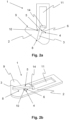
- Figure 1a shows a top view of a first exemplary embodiment of a guide device 1 according to the invention.
- the guide device 1 comprises a first guide element 2 and a second guide element 3, which are arranged one above the other.
- the first guide element 2 has a first guide section 4.
- the second guide element 3 has a second guide section 5.
- the first guide section 4 and the second guide section 5 together form a guide area 6 in which a strand-shaped fiber structure 7 (see Figure 4 ) is guided when the guide device 1 is used as intended.
- the first guide section 4 and the second guide section 5 form the guide area 6 in the form of a closed contour.
- the closed contour of the guide area 6 has the shape of a circle.
- the contour of the guide area 6 can also have the shape of an ellipse or a drop, for example.
- first guide element 2 and the second guide element 3 are arranged spaced apart from one another at least in a front region.
- a distance between the first guide element 2 and the second guide element 3 forms an opening 8, which is suitable for easily threading the fiber structure 7 into the guide area 6.
- the first guide element 2 and the second guide element 3 are arranged essentially parallel to one another.
- the first guide element 2 forms a first level and the second guide element 3 forms a second level, the levels being parallel to one another.
- the first guide element 2 and the second guide element 3 are plate-shaped.
- the first guide element 2 and the second guide element 3 are designed as metallic stamped parts.
- the first guide element 2 has an arm 9.
- the arm 9 merges into an entry area 10.
- the fiber structure 7 is initially captured by the arm 9, for example.
- the fiber structure 7 is then brought into the first guide section 4 via the entry area 10.
- the fiber structure 7 is simultaneously or subsequently brought into the second guide section 5 of the second guide element 3.
- the arm 9 extends in the top view Figure 1a beyond the second guide element 3.
- the arm 9 can fulfill the function of catching the fiber structure 7 without the fiber structure 7 getting caught in other areas of the guide device 1.
- the first guide element 2 and the second guide element 3 each have a recess 11, which is used to fasten the guide device 1 to a carrier 12 of a workstation 13 (see Figure 4 ) is used for a ring spinning machine.
- the recesses 11 lie one above the other, so that essentially a continuous recess 11 results.
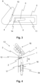
- the Figures 2a and 2b show a further exemplary embodiment of the guide device 1 according to the invention, wherein the Figure 2a another one Top view of the guide device 1 and the Figure 2a a perspective view of the guide device 1.
- the first guide element 2 and the second guide element 3 are initially designed as a common component. This is also shown in more detail in Figure 3.
- the essential features of the guide device 1 from this exemplary embodiment correspond to those of the first exemplary embodiment from the Figures 1a and 1b .
- the arrangement of the first guide section 4 of the first guide element 2 and the second guide section 5 of the second guide element 3 results in a guide area 6 with a closed contour.
- a significant difference from the first exemplary embodiment is that the first guide element 2 and the second guide element 3 are connected to one another via a connecting section 14.
- the connecting section 14 runs essentially perpendicular to the first guide element 2 and to the second guide element 3.
- the threading process of the fiber structure 7 described in the first exemplary embodiment runs the same way in this exemplary embodiment of the guide device 1.
- the first guide element 2 has the recess 11, which is used for fastening the guide device 1 on the carrier 12 of the workstation 13 of the ring spinning machine is used.
- the Figure 3 indicates an intermediate step in a manufacturing process of the guide device 1 according to the second exemplary embodiment.
- the first guide element 2 and the second guide element 3 are, for example, initially manufactured as a common stamped part.
- the second guide element 3 is initially provided in the recess 11.
- the second guide element 3 is bent upwards and aligned essentially parallel to the first guide element 2.
- the end result of the manufacturing process is the guide device 1 according to the exemplary embodiment Figures 2a and 2b .
- Figure 4 shows the workstation 13 of the ring spinning machine, not shown, with the guide device 1 according to the invention.
- the guide device 1 is suitable for guiding the strand-shaped fiber structure 7, in particular for restricting freedom of movement of the fiber structure 7 perpendicular to a running direction 15 of the fiber structure 7 .
- the first guide element 2 and the second guide element 3 are arranged one above the other in the workstation 13.
- the guide device 1 is arranged between a drafting system 16 and a spinning ring 17.
- the fiber structure 7 is first stretched in the drafting system 16 and then wound onto a spinning tube 19 via a ring traveler 18 rotating on the spinning ring 17. This gives the fiber structure 7 a twist.
- the guide device 1 is fastened via the recess 11 in the carrier 12 of the workstation 13.
Abstract
Die vorliegende Erfindung betrifft eine Führungsvorrichtung (1) für eine Ringspinnmaschine zum Führen eines strangförmigen Faserverbands (7) mit einem Führungsbereich (6), der eine Bewegungsfreiheit des Faserverbands (7) senkrecht zu einer Laufrichtung (15) des Faserverbands (7) beschränkt und mit einer Öffnung (8) zum Einbringen des Faserverbands (7) in den Führungsbereich (6). Außerdem betrifft die Erfindung eine Ringspinnmaschine mit wenigstens einer Arbeitsstelle (13) zur Herstellung eines Garns, wobei die Arbeitsstelle (13) ein Streckwerk (16) zum Verstrecken eines Faserverbands (7), einen auf einem Spinnring (17) umlaufenden Ringläufer (18) und eine Führungsvorrichtung (1) zum Führen des Faserverbands (7) aufweist. Darüber hinaus betrifft die Erfindung die Verwendung einer Führungsvorrichtung (1) in einer Ringspinnmaschine. Erfindungsgemäß wird vorgeschlagen, dass die Führungsvorrichtung (1) ein erstes Führungselement (2) mit einem ersten Führungsabschnitt (4) und ein zweites Führungselement (3) mit einem zweiten Führungsabschnitt (5) aufweist. Der erste Führungsabschnitt (4) und der zweite Führungsabschnitt (5) bilden in einer Draufsicht auf die Führungsvorrichtung (1) gemeinsam den Führungsbereich (6) in Form einer geschlossenen Kontur.The present invention relates to a guide device (1) for a ring spinning machine for guiding a strand-shaped fiber structure (7) with a guide area (6) which limits freedom of movement of the fiber structure (7) perpendicular to a running direction (15) of the fiber structure (7) and with an opening (8) for introducing the fiber structure (7) into the guide area (6). The invention also relates to a ring spinning machine with at least one work station (13) for producing a yarn, the work station (13) having a drafting system (16) for stretching a fiber structure (7), a ring traveler (18) rotating on a spinning ring (17), and has a guide device (1) for guiding the fiber structure (7). The invention further relates to the use of a guide device (1) in a ring spinning machine. According to the invention, it is proposed that the guide device (1) has a first guide element (2) with a first guide section (4) and a second guide element (3) with a second guide section (5). In a plan view of the guide device (1), the first guide section (4) and the second guide section (5) together form the guide area (6) in the form of a closed contour.
Description
Die vorliegende Erfindung betrifft eine Führungsvorrichtung für eine Ringspinnmaschine zum Führen eines strangförmigen Faserverbands mit einem Führungsbereich, der eine Bewegungsfreiheit des Faserverbands senkrecht zu einer Laufrichtung des Faserverbands beschränkt und mit einer Öffnung zum Einbringen des Faserverbands in den Führungsbereich. Außerdem betrifft die Erfindung eine Ringspinnmaschine mit wenigstens einer Arbeitsstelle zur Herstellung eines Garns, wobei die Arbeitsstelle ein Streckwerk zum Verstrecken eines Faserverbands, einen auf einem Spinnring umlaufenden Ringläufer und eine Führungsvorrichtung zum Führen des Faserverbands aufweist. Darüber hinaus betrifft die Erfindung die Verwendung einer Führungsvorrichtung in einer Ringspinnmaschine.The present invention relates to a guide device for a ring spinning machine for guiding a strand-shaped fiber structure with a guide area which limits freedom of movement of the fiber structure perpendicular to a running direction of the fiber structure and with an opening for introducing the fiber structure into the guide area. The invention also relates to a ring spinning machine with at least one workstation for producing a yarn, the workstation having a drafting system for stretching a fiber structure, a ring traveler rotating on a spinning ring and a guide device for guiding the fiber structure. In addition, the invention relates to the use of a guide device in a ring spinning machine.
Ringspinnmaschinen zur Herstellung eines Garns aus einem Faserverband sind seit langem bekannt. In der Regel weisen Ringspinnmaschinen ein Streckwerk zum Verstrecken des Faserverbands auf. Der verstreckte Faserverband wird nach dem Streckwerk über einen auf einem Spinnring umlaufenden Ringläufer auf eine Spinnhülse gewickelt. Hierbei erhält der Faserverband einen Drall und wird zu einem Garn. Um den Verlauf des Faserverbands zwischen dem Streckwerk und dem Spinnring kontrollieren zu können, weist die Ringspinnmaschine in der Regel wenigstens eine Führungsvorrichtung auf, durch die zumindest eine Bewegung des Faserverbands senkrecht zu seiner Laufrichtung begrenzt wird. Durch die Führungsvorrichtung können einerseits ungewünschte Bewegungen des Faserverbands vermieden werden. Andererseits kann auch die Spannung des Faserverbands durch die Führungsvorrichtung gezielt kontrolliert werden. Zum Einfädeln des Faserverbands weisen bekannte Führungsvorrichtungen in der Regel eine Öffnung auf, über die der Faserverband beispielsweise vor einem erneuten Anspinnen in einen Führungsbereich der Führungsvorrichtung gebracht werden kann.Ring spinning machines for producing a yarn from a fiber structure have been known for a long time. As a rule, ring spinning machines have a drafting system for stretching the fiber structure. After the drafting system, the stretched fiber structure is wound onto a spinning tube via a ring runner rotating on a spinning ring. This gives the fiber structure a twist and turns it into a yarn. In order to be able to control the course of the fiber structure between the drafting system and the spinning ring, the ring spinning machine usually has at least one guide device, through which at least one movement of the fiber structure is limited perpendicular to its direction of travel. On the one hand, the guide device can prevent unwanted movements of the fiber structure. On the other hand, the tension of the fiber structure can also be specifically controlled by the guide device. Known guide devices generally have an opening for threading the fiber structure on, via which the fiber structure can be brought into a guide area of the guide device, for example before spinning again.
Bei derartigen bekannten Führungsvorrichtungen handelt es sich beispielsweise um spiralförmig gebogene Drähte, wie sie beispielsweise in der
Aufgabe der vorliegenden Erfindung ist es, die aus dem Stand der Technik bekannten Nachteile zu beseitigen, insbesondere eine Führungsvorrichtung für eine Ringspinnmaschine zu schaffen, die die genannten Nachteile überwindet.The object of the present invention is to eliminate the disadvantages known from the prior art, in particular to create a guide device for a ring spinning machine which overcomes the disadvantages mentioned.
Die Aufgabe wird gelöst durch eine Führungsvorrichtung, eine Ringspinnmaschine und eine Verwendung einer Führungsvorrichtung mit den Merkmalen der unabhängigen Patentansprüche.The task is solved by a guide device, a ring spinning machine and the use of a guide device with the features of the independent claims.
Vorgeschlagen wird eine Führungsvorrichtung für eine Ringspinnmaschine zum Führen eines strangförmigen Faserverbands mit einem Führungsbereich, der eine Bewegungsfreiheit des Faserverbands senkrecht zu einer Laufrichtung des Faserverbands beschränkt und mit einer Öffnung zum Einbringen des Faserverbands in den Führungsbereich. Erfindungsgemäß wird vorgeschlagen, dass die Führungsvorrichtung ein erstes Führungselement mit einem ersten Führungsabschnitt und ein zweites Führungselement mit einem zweiten Führungsabschnitt aufweist. Der erste Führungsabschnitt und der zweite Führungsabschnitt bilden in einer Draufsicht auf die Führungsvorrichtung gemeinsam den Führungsbereich in Form einer geschlossenen Kontur.What is proposed is a guide device for a ring spinning machine for guiding a strand-shaped fiber structure with a guide area that limits freedom of movement of the fiber structure perpendicular to a running direction of the fiber structure and with an opening for introducing the fiber structure into the guide area. According to the invention, it is proposed that the guide device has a first guide element with a first guide section and a second guide element with a second guide section. The first leadership section and the second guide section together form the guide area in the form of a closed contour in a top view of the guide device.
Durch das erste Führungselement und das insbesondere vom ersten Führungselement getrennte zweite Führungselement, ist es einerseits unkompliziert den Faserverband in die Führungsvorrichtung bzw. den Führungsbereich der Führungsvorrichtung einzufädeln. Andererseits lässt sich die vorgeschlagene Führungsvorrichtung im Vergleich zu den bekannten Führungsvorrichtungen leichter reinigen. Das erste Führungselement und das zweite Führungselement lassen sich in einfacher Weise derart beabstanden, dass sich weniger Fasern an der Führungsvorrichtung festsetzen. Die geschlossene Kontur verhindert darüber hinaus, dass der Faserverband aus dem Führungsbereich der Führungsvorrichtung herausspringt oder sonstige ungewollte Bewegungen vollzieht. Die Führungsvorrichtung beschränkt die Bewegungsfreiheit des Faserverbands insbesondere senkrecht zu dessen Laufrichtung in einer Ringspinnmaschine. Es ist ebenfalls denkbar, dass eine Bewegungsfreiheit des Faserverbands in anderen Richtungen durch die Führungsvorrichtung beschränkt wird.Due to the first guide element and the second guide element, which is in particular separated from the first guide element, it is, on the one hand, uncomplicated to thread the fiber structure into the guide device or the guide area of the guide device. On the other hand, the proposed guide device can be cleaned more easily compared to the known guide devices. The first guide element and the second guide element can be easily spaced apart in such a way that fewer fibers get stuck on the guide device. The closed contour also prevents the fiber structure from jumping out of the guide area of the guide device or making other unwanted movements. The guide device limits the freedom of movement of the fiber structure, particularly perpendicular to its direction of travel in a ring spinning machine. It is also conceivable that freedom of movement of the fiber structure in other directions is restricted by the guide device.
Vorteile bringt es zudem mit sich, wenn in der Draufsicht auf die Führungsvorrichtung die geschlossene Kontur des Führungsbereichs die Form eines Kreises, einer Ellipse oder eines Tropfens aufweist. Die Kontur des Führungsbereichs kann insbesondere an die Form der Bewegung des Faserverbands, die dieser durch die Führung des Ringläufers ausführt, angepasst werden. Hierdurch kann unnötige Reibung des Faserverbands an der Führungsvorrichtung und damit das Herauslösen zusätzlicher Fasern vermieden werden. Auch lässt sich beispielsweise die Spannung des Faserverbands durch die Form der Kontur des Führungsbereichs beeinflussen.There are also advantages if, in the top view of the guide device, the closed contour of the guide area has the shape of a circle, an ellipse or a drop. The contour of the guide area can be adapted in particular to the shape of the movement of the fiber structure, which it carries out through the guidance of the ring traveler. In this way, unnecessary friction of the fiber structure on the guide device and thus the detachment of additional fibers can be avoided. For example, the tension of the fiber structure can also be influenced by the shape of the contour of the guide area.
Vorteile bringt es mit sich, wenn das erste Führungselement und das zweite Führungselement im Wesentlichen parallel zueinander angeordnet sind. Dies trägt zu einer weiteren Vereinfachung des Einfädelns des Faserverbands in den Führungsbereich der Führungsvorrichtung bei. Das erste Führungselement und das zweite Führungselement können beispielsweise plattenförmig ausgebildet sein. Das erste Führungselement und das zweite Führungselement können insbesondere jeweils in einer Ebene angeordnet sein, wobei die Ebenen entsprechend im Wesentlichen parallel zueinander sind. Insbesondere sind das erste Führungselement und das zweite Führungselement parallel zueinander angeordnet. Es ist denkbar, dass das erste Führungselement und/oder das zweite Führungselement mehrere flächige Abschnitte umfassen, die wiederum parallel zueinander verlaufen.There are advantages when the first guide element and the second guide element are arranged essentially parallel to one another. This contributes to further simplifying the threading of the fiber structure into the guide area of the guide device. The first guide element and the second guide element can, for example, be plate-shaped. The first guide element and the second guide element can in particular each be arranged in a plane, the planes being essentially parallel to one another. In particular, the first guide element and the second guide element are arranged parallel to one another. It is conceivable that the first guide element and/or the second guide element comprise a plurality of flat sections, which in turn run parallel to one another.
Ebenso bringt es Vorteile mit sich, wenn das erste Führungselement und das zweite Führungselement bei bestimmungsgemäßem Gebrauch der Führungsvorrichtung übereinander angeordnet sind. Hierdurch lässt sich in effizienter Weise beispielsweise die geschlossene Kontur des Führungsbereichs konstruktiv verwirklichen. Insbesondere sind das erste Führungselement und das zweite Führungselement in zwei parallelen Ebenen übereinander angeordnet.It also brings advantages if the first guide element and the second guide element are arranged one above the other when the guide device is used as intended. In this way, for example, the closed contour of the guide area can be constructively implemented in an efficient manner. In particular, the first guide element and the second guide element are arranged one above the other in two parallel planes.
Ebenso ist es vorteilhaft, wenn das erste Führungselement und das zweite Führungselement über einen Verbindungsabschnitt miteinander verbunden sind, wobei der Verbindungsabschnitt senkrecht zu dem ersten Führungselement und dem zweiten Führungselement verläuft. Der Verbindungsabschnitt erhöht die Stabilität der Führungsvorrichtung. Es ist denkbar, dass bei der Herstellung das erste Führungselement und das zweite Führungselement zunächst als gemeinsames Bauteil hergestellt werden, beispielsweise als ein Stanzteil. Das zweite Führungselement kann dann beispielsweise in einem weiteren Herstellungsschritt aus der Ebene des ersten Führungselements herausgebogen werden und dann im Wesentlichen parallel zum ersten Führungselement ausgerichtet werden. Der Verbindungsabschnitt ergibt sich dann aus dem gebogenen Abschnitt zwischen dem ersten Führungselement und dem zweiten Führungselement. Falls das erste Führungselement und das zweite Führungselement als getrennte Bauteile vorgesehen werden, kann der Verbindungsabschnitt beispielsweise durch ein oder mehrere Verbindungselemente, wie zum Beispiel Schrauben, Bolzen oder Klemmen, gebildet werden.It is also advantageous if the first guide element and the second guide element are connected to one another via a connecting section, the connecting section running perpendicular to the first guide element and the second guide element. The connecting section increases the stability of the guide device. It is conceivable that during production the first guide element and the second guide element are initially produced as a common component, for example as a stamped part. The second guide element can then, for example, in a further manufacturing step from the plane of the first guide element be bent out and then aligned essentially parallel to the first guide element. The connecting section then results from the curved section between the first guide element and the second guide element. If the first guide element and the second guide element are provided as separate components, the connecting section can be formed, for example, by one or more connecting elements, such as screws, bolts or clamps.
Vorteile bringt es mit sich, wenn die Öffnung zumindest teilweise von einem Abstand zwischen dem ersten Führungselement und dem zweiten Führungselement gebildet wird. Dies trägt zu einer weiteren Vereinfachung des Einfädelvorgangs des Faserverbands in den Führungsbereich der Führungsvorrichtung bei. Für ein Einfädeln des Faserverbands in die Führungsvorrichtung muss der Faserverband temporär entlang der Öffnung, also entlang des Abstands zwischen dem ersten Führungselement und dem zweiten Führungselement ausgerichtet werden. Falls das erste Führungselement und das zweite Führungselement, wie zuvor beschrieben, parallel zueinander ausgerichtet sind, muss der Faserverband zum Einfädeln beispielsweise ebenfalls im Wesentlichen parallel zu den beiden Führungselementen ausgerichtet werden. Die Größe des Abstands zwischen dem ersten Führungselement und dem zweiten Führungselement kann derart gewählt werden, dass ein automatisches Einfädeln des Faserverbands in den Führungsbereich der Führungsvorrichtung problemlos möglich ist.There are advantages if the opening is at least partially formed by a distance between the first guide element and the second guide element. This contributes to further simplifying the threading process of the fiber structure into the guide area of the guide device. In order to thread the fiber structure into the guide device, the fiber structure must be temporarily aligned along the opening, i.e. along the distance between the first guide element and the second guide element. If the first guide element and the second guide element are aligned parallel to one another, as described above, the fiber structure for threading must also be aligned essentially parallel to the two guide elements, for example. The size of the distance between the first guide element and the second guide element can be selected such that automatic threading of the fiber structure into the guide area of the guide device is possible without any problems.
Ebenso ist es vorteilhaft, wenn das erste Führungselement einen mit dem ersten Führungsabschnitt verbundenen Eintrittsbereich aufweist. Über den Eintrittsbereich kann der Faserverband beim Einfädeln in den ersten Führungsabschnitt geleitet werden. Der Eintrittsbereich kann beispielsweise in Form eines Kanals mit parallelen Seitenwänden ausgebildet sein. Er führt insbesondere von einer Außenkante des ersten Führungselements zum ersten Führungsabschnitt, der beispielsweise im Wesentlichen mittig zwischen zwei Außenkanten des ersten Führungselements angeordnet ist. Je nachdem wie die Seitenwände des Eintrittsbereichs beabstandet sind, lässt sich eine Bewegungsfreiheit des Faserverbands beim Einfädeln beschränken.It is also advantageous if the first guide element has an entry area connected to the first guide section. The fiber structure can be guided via the entry area when threading into the first guide section. The entry area can, for example, be designed in the form of a channel with parallel side walls. He leads in particular from an outer edge of the first guide element to the first guide section, which is arranged, for example, essentially centrally between two outer edges of the first guide element. Depending on how the side walls of the entry area are spaced, the freedom of movement of the fiber structure when threading can be limited.
Vorteile bringt es zudem mit sich, wenn der Eintrittsbereich zumindest teilweise von einem Arm gebildet wird, der sich in der Draufsicht der Führungsvorrichtung über das zweite Führungselement hinaus erstreckt. Der Arm kann beispielsweise zum Einfangen und Fixieren des Faserverbands beim Einfädeln dienen. Eine Außenkante des Arms kann beispielsweise direkt in eine der bereits beschriebenen Seitenwände des Eintrittsbereichs übergehen. Das Einfädeln des Faserverbands zunächst in den ersten Führungsabschnitt und anschließend in den zweiten Führungsabschnitt des zweiten Führungselements insbesondere durch einen Roboter wird hierdurch weiter vereinfacht.There are also advantages if the entry area is at least partially formed by an arm which extends beyond the second guide element in the top view of the guide device. The arm can be used, for example, to catch and fix the fiber structure when threading. An outer edge of the arm can, for example, merge directly into one of the side walls of the entry area already described. This further simplifies the threading of the fiber structure first into the first guide section and then into the second guide section of the second guide element, in particular by a robot.
Ein beispielhafter Einfädelvorgang des Faserverbands in den Führungsbereich der Führungsvorrichtung kann folgendermaßen aussehen. Zunächst wird der Faserverband in den Bereich des Arms gebracht und von diesem eingefangen. Dann wird der Faserverband in Richtung des ersten Führungsabschnitts bewegt. Der Faserverband bewegt sich entlang des Arms und des Eintrittsbereichs in den ersten Führungsabschnitt. Gleichzeitig oder anschließend wird der Faserverband zumindest teilweise entlang der Öffnung zwischen dem ersten und dem zweiten Führungselement ausgerichtet. Hierdurch kann der Faserverband in den zweiten Führungsabschnitt des zweiten Führungselements gebracht werden, womit der Vorgang abgeschlossen ist.An exemplary threading process of the fiber structure into the guide area of the guide device can look like this. First, the fiber bandage is brought into the area of the arm and captured by it. The fiber structure is then moved in the direction of the first guide section. The fiber structure moves along the arm and the entry area into the first guide section. At the same time or subsequently, the fiber structure is at least partially aligned along the opening between the first and second guide elements. As a result, the fiber structure can be brought into the second guide section of the second guide element, which completes the process.
Ebenso ist es vorteilhaft, wenn das erste Führungselement und/oder das zweite Führungselement zumindest teilweise als Stanzteil, vorzugsweise aus Metall, ausgebildet ist. Hierdurch lässt sich die Führungsvorrichtung in besonders einfacher und kostengünstiger Weise herstellen. Metall ist ein robuster und langlebiger Werkstoff. Das erste und/oder das zweite Führungselement können nach dem Stanzen beispielsweise durch Gleitschleifen geglättet werden. Insbesondere werden dadurch die Kanten der Bauteile abgerundet, sodass eine Beschädigung des Faserverbands weniger wahrscheinlich ist. Das erste Führungselement und/oder das zweite Führungselement können ebenfalls mit einem oder mehreren Abbugen, insbesondere im Bereich der Kanten, versehen werden. Hierdurch kann die Stabilität der Bauteile erhöht werden. Auch sind verschiedene Härtungsprozesse für die Stanzteiledenkbar.It is also advantageous if the first guide element and/or the second guide element are at least partially made as a stamped part, preferably Metal, is formed. This allows the guide device to be manufactured in a particularly simple and cost-effective manner. Metal is a robust and durable material. The first and/or the second guide element can be smoothed after punching, for example by vibratory grinding. In particular, this rounds off the edges of the components so that damage to the fiber structure is less likely. The first guide element and/or the second guide element can also be provided with one or more bends, particularly in the area of the edges. This can increase the stability of the components. Various hardening processes for the stamped parts are also conceivable.
Das erste Führungselement und das zweite Führungselement können beispielsweise als einzelne Stanzteile hergestellt werden. Diese werden anschließend zu der Führungsvorrichtung zusammengefügt. Wie bereits erwähnt, können das erste Führungselement und das zweite Führungselement insbesondere auch als ein einzelnes Stanzteil hergestellt werden. Das zweite Führungselement wird dann beispielsweise in einem weiteren Verfahrensschritt aus der Ebene des ersten Führungselements herausgebogen und vorzugsweise im Wesentlichen parallel zum ersten Führungselement ausgerichtet.The first guide element and the second guide element can be produced, for example, as individual stamped parts. These are then assembled to form the guide device. As already mentioned, the first guide element and the second guide element can in particular also be produced as a single stamped part. The second guide element is then bent out of the plane of the first guide element, for example in a further method step, and preferably aligned essentially parallel to the first guide element.
Vorteilhaft ist es zudem, wenn das erste Führungselement und/oder das zweite Führungselement eine Aussparung aufweist, wobei die Aussparung der Befestigung der Führungsvorrichtung an einem Träger einer Arbeitsstelle einer Ringspinnmaschine dient. Hierdurch kann die Führungsvorrichtung stabil mit der Arbeitsstelle der Ringspinnmaschine verbunden werden. Die Aussparung kann nach außen hin geschlossen oder auch offen ausgebildet sein. Insbesondere dient die Aussparung der Aufnahme oder dem Durchgang einer Schraube, mit deren Hilfe das Führungselement mit dem Träger verbunden werden kann. Insbesondere ist die Aussparung nicht mit dem ersten Führungsabschnitt und dem zweiten Führungsabschnitt verbunden.It is also advantageous if the first guide element and/or the second guide element has a recess, the recess serving to fasten the guide device to a support of a workstation of a ring spinning machine. This allows the guide device to be stably connected to the workstation of the ring spinning machine. The recess can be closed to the outside or open. In particular, the recess serves to accommodate or pass through a screw, with the help of which the guide element is connected to the carrier can be connected. In particular, the recess is not connected to the first guide section and the second guide section.
Die erfindungsgemäße Ringspinnmaschine umfasst wenigstens eine Arbeitsstelle zur Herstellung eines Garns. Die Arbeitsstelle weist ein Streckwerk zum Verstrecken eines Faserverbands, einen auf einem Spinnring umlaufenden Ringläufer und eine Führungsvorrichtung zum Führen des Faserverbands auf. Es wird für die Ringspinnmaschine vorgeschlagen, dass die Führungsvorrichtung gemäß der vorangegangenen Beschreibung ausgebildet ist. Die genannten Merkmale können dabei einzeln oder in beliebiger Kombination verwirklicht sein. Die beschriebenen Vorteile ergeben sich durch das Vorsehen der erfindungsgemäßen Führungsvorrichtung auch für die Ringspinnmaschine. Insbesondere sind ein Einfädeln des Faserverbands in die Führungsvorrichtung und eine Reinigung der Führungsvorrichtung bei der Ringspinnmaschine vereinfacht.The ring spinning machine according to the invention comprises at least one workstation for producing a yarn. The workstation has a drafting system for stretching a fiber structure, a ring traveler rotating on a spinning ring and a guide device for guiding the fiber structure. It is proposed for the ring spinning machine that the guide device is designed according to the previous description. The features mentioned can be implemented individually or in any combination. The advantages described also result from the provision of the guide device according to the invention for the ring spinning machine. In particular, threading the fiber structure into the guide device and cleaning the guide device on the ring spinning machine are simplified.
Für die Ringspinnmaschine ist es vorteilhaft, wenn die Führungsvorrichtung zwischen dem Streckwerk und dem Spinnring angeordnet ist. In dem Bereich zwischen dem Streckwerk und dem Spinnring ist eine Führung des Faserverbands besonders wichtig, um einerseits Beschädigungen des Faserverbands zu vermeiden und andererseits die Spannung des Faserverbands zu kontrollieren. Die Vorteile der erfindungsgemäßen Führungsvorrichtung entfalten sich in diesem Bereich daher in besonderer Weise. Es ist denkbar, dass zwischen dem Streckwerk und dem Spinnring ebenfalls einer oder mehrere Balloneinengungsringe angeordnet sind, um die Ausdehnung der eventuell durch den Umlauf des Spinnrings entstehenden Ballone des Faserverbands zu beschränken.It is advantageous for the ring spinning machine if the guide device is arranged between the drafting system and the spinning ring. In the area between the drafting system and the spinning ring, guidance of the fiber structure is particularly important in order to avoid damage to the fiber structure on the one hand and to control the tension of the fiber structure on the other hand. The advantages of the guide device according to the invention therefore unfold in a special way in this area. It is conceivable that one or more balloon constriction rings are also arranged between the drafting system and the spinning ring in order to limit the expansion of the balloons of the fiber structure that may arise as a result of the rotation of the spinning ring.
Erfindungsgemäß wird ebenfalls die Verwendung einer Führungsvorrichtung gemäß der vorangegangenen Beschreibung in einer Ringspinnmaschine vorgeschlagen, wobei die Ringspinnmaschine insbesondere wie zuvor beschreiben ausgebildet ist. Wie bereits beschrieben, ist es für den Betrieb einer Ringspinnmaschine vorteilhaft, eine erfindungsgemäße Führungsvorrichtung zum Führen eines Faserverbands zu verwenden. Insbesondere gestaltet sich das Einfädeln des Faserverbands in die Führungsvorrichtung und die Reinigung der Führungsvorrichtung einfacher.According to the invention, the use of a guide device according to the previous description in a ring spinning machine is also proposed, wherein the ring spinning machine is designed in particular as described above. As already described, it is advantageous for the operation of a ring spinning machine to use a guide device according to the invention for guiding a fiber structure. In particular, threading the fiber structure into the guide device and cleaning the guide device are easier.
Weitere Vorteile der Erfindung sind in den nachfolgenden Ausführungsbeispielen beschrieben. Es zeigt:
- Figur 1a
- eine Draufsicht auf ein erstes Ausführungsbeispiel einer erfindungsgemäßen Führungsvorrichtung,
- Figur 1b
- eine perspektivische Ansicht des ersten Ausführungsbeispiels der erfindungsgemäßen Führungsvorrichtung,
- Figur 2a
- eine Draufsicht auf ein zweites Ausführungsbeispiel der erfindungsgemäßen Führungsvorrichtung,
- Figur 2b
- eine perspektivische Ansicht des zweiten Ausführungsbeispiels der erfindungsgemäßen Führungsvorrichtung,
Figur 3- eine Draufsicht auf die Führungsvorrichtung des zweiten Ausführungsbeispiels während des Herstellungsprozesses, und
Figur 4- eine Arbeitsstelle einer Ringspinnmaschine mit der erfindungsgemäßen Führungsvorrichtung.
- Figure 1a
- a top view of a first exemplary embodiment of a guide device according to the invention,
- Figure 1b
- a perspective view of the first exemplary embodiment of the guide device according to the invention,
- Figure 2a
- a top view of a second exemplary embodiment of the guide device according to the invention,
- Figure 2b
- a perspective view of the second exemplary embodiment of the guide device according to the invention,
- Figure 3
- a top view of the guide device of the second exemplary embodiment during the manufacturing process, and
- Figure 4
- a workstation of a ring spinning machine with the guide device according to the invention.
Bei der nachfolgenden Beschreibung der Figuren werden für in den verschiedenen Figuren jeweils identische und/oder zumindest vergleichbare Merkmale gleiche Bezugszeichen verwendet. Die einzelnen Merkmale, deren Ausgestaltung und/oder Wirkweise werden meist nur bei ihrer ersten Erwähnung ausführlich erläutert. Werden einzelne Merkmale nicht nochmals detailliert erläutert, so entspricht deren Ausgestaltung und/oder Wirkweise der Ausgestaltung und Wirkweise der bereits beschriebenen gleichwirkenden oder gleichnamigen Merkmale.In the following description of the figures, identical and/or at least comparable features are used in the various figures same reference numerals used. The individual features, their design and/or mode of operation are usually only explained in detail when they are first mentioned. If individual features are not explained again in detail, their design and/or mode of operation corresponds to the design and mode of operation of the features with the same effect or the same name that have already been described.
Der erste Führungsabschnitt 4 und der zweite Führungsabschnitt 5 bilden in dieser Draufsicht den Führungsbereich 6 in Form einer geschlossenen Kontur. In diesem Ausführungsbeispiel besitzt die geschlossene Kontur des Führungsbereichs 6 die Form eines Kreises. Alternativ kann die Kontur des Führungsbereichs 6 aber ebenso beispielsweise die Form einer Ellipse oder eines Tropfens aufweisen.In this top view, the
Wie in der perspektivischen Ansicht der
Das erste Führungselement 2 und das zweite Führungselement 3 sind im Wesentlichen parallel zueinander angeordnet. Insbesondere bildet das erste Führungselement 2 eine erste Ebene und das zweite Führungselement 3 eine zweite Ebene, wobei die Ebenen parallel zueinander sind. Das erste Führungselement 2 und das zweite Führungselement 3 sind plattenförmig ausgebildet. In diesem Ausführungsbeispiel sind das erste Führungselement 2 und das zweite Führungselement 3 als metallische Stanzteile ausgebildet.The
Zum erleichterten Einfädeln des Faserverbands 7 weist das erste Führungselement 2 einen Arm 9 auf. Der Arm 9 geht über in einen Eintrittsbereich 10. Beim Einfädeln des Faserverbands 7 wird dieser beispielsweise zunächst von dem Arm 9 eingefangen. Der Faserverband 7 wird anschließend über den Eintrittsbereich 10 in den ersten Führungsabschnitt 4 verbracht. Durch eine Ausrichtung des Faserverbands 7 entlang der Öffnung 8 wird der Faserverband 7 gleichzeitig oder anschließend in den zweiten Führungsabschnitt 5 des zweiten Führungselements 3 verbracht. Der Arm 9 erstreckt sich in der Draufsicht der
Das erste Führungselement 2 und das zweite Führungselement 3 weisen jeweils eine Aussparung 11 auf, die zum Befestigen der Führungsvorrichtung 1 an einem Träger 12 einer Arbeitsstelle 13 (siehe
Die
Ein wesentlicher Unterschied zum ersten Ausführungsbeispiel besteht darin, dass das erste Führungselement 2 und das zweite Führungselement 3 über einen Verbindungsabschnitt 14 miteinander verbunden sind. Der Verbindungsabschnitt 14 verläuft im Wesentlichen senkrecht zum ersten Führungselement 2 und zum zweiten Führungselement 3. Der im Rahmen des ersten Ausführungsbeispiels beschriebene Einfädelprozess des Faserverbands 7 verläuft genauso bei diesem Ausführungsbeispiel der Führungsvorrichtung 1. Das erste Führungselement 2 weist die Aussparung 11 auf, die zum Befestigen der Führungsvorrichtung 1 an dem Träger 12 der Arbeitsstelle 13 der Ringspinnmaschine dient.A significant difference from the first exemplary embodiment is that the
Die
Bei der Herstellung eines Garns an der Arbeitsstelle 13 wird der Faserverband 7 zunächst in dem Streckwerk 16 verstreckt und anschließend über einen auf dem Spinnring 17 umlaufenden Ringläufer 18 auf eine Spinnhülse 19 aufgewickelt. Hierdurch wird dem Faserverband 7 ein Drall verliehen. Die Führungsvorrichtung 1 ist über die Aussparung 11 in dem Träger 12 der Arbeitsstelle 13 befestigt.When producing a yarn at the
Die vorliegende Erfindung ist nicht auf die dargestellten und beschriebenen Ausführungsbeispiele beschränkt. Abwandlungen im Rahmen der Patentansprüche sind ebenso möglich wie eine Kombination der Merkmale, auch wenn diese in unterschiedlichen Ausführungsbeispielen dargestellt und beschrieben sind.The present invention is not limited to the exemplary embodiments shown and described. Modifications within the scope of the patent claims are possible, as is a combination of the features, even if these are shown and described in different exemplary embodiments.
- 11
- FührungsvorrichtungGuidance device
- 22
- erstes Führungselementfirst leadership element
- 33
- zweites Führungselementsecond leadership element
- 44
- erster Führungsabschnittfirst tour section
- 55
- zweiter Führungsabschnittsecond tour section
- 66
- FührungsbereichLeadership area
- 77
- FaserverbandFiber bandage
- 88th
- Öffnungopening
- 99
- Armpoor
- 1010
- EintrittsbereichEntry area
- 1111
- Aussparungrecess
- 1212
- Trägercarrier
- 1313
- Arbeitsstelleplace of work
- 1414
- Verbindungsabschnittconnection section
- 1515
- LaufrichtungRunning direction
- 1616
- StreckwerkDrafting system
- 1717
- SpinnringSpinning ring
- 1818
- RingläuferRing runner
- 1919
- SpinnhülseSpinning tube
Claims (13)
dadurch gekennzeichnet, dass die Führungsvorrichtung (1) ein erstes Führungselement (2) mit einem ersten Führungsabschnitt (4) und ein zweites Führungselement (3) mit einem zweiten Führungsabschnitt (5) aufweist, wobei der erste Führungsabschnitt (4) und der zweite Führungsabschnitt (5) in einer Draufsicht auf die Führungsvorrichtung (1) gemeinsam den Führungsbereich (6) in Form einer geschlossenen Kontur bilden.Guide device (1) for a ring spinning machine for guiding a strand-shaped fiber structure (7) with a guide area (6) which limits freedom of movement of the fiber structure (7) perpendicular to a running direction (15) of the fiber structure (7) and with an opening (8) for introducing the fiber structure (7) into the guide area (6),
characterized in that the guide device (1) has a first guide element (2) with a first guide section (4) and a second guide element (3) with a second guide section (5), the first guide section (4) and the second guide section ( 5) in a top view of the guide device (1) together form the guide area (6) in the form of a closed contour.
dadurch gekennzeichnet, dass in der Draufsicht auf die Führungsvorrichtung (1) die geschlossene Kontur des Führungsbereichs (6) die Form eines Kreises, einer Ellipse oder eines Tropfens aufweist.Guide device (1) according to the preceding claim,
characterized in that in the top view of the guide device (1), the closed contour of the guide area (6) has the shape of a circle, an ellipse or a drop.
dadurch gekennzeichnet, dass der Eintrittsbereich (10) zumindest teilweise von einem Arm (9) gebildet wird, der sich in der Draufsicht der Führungsvorrichtung (1) über das zweite Führungselement (3) hinaus erstreckt.Guide device (1) according to the preceding claim,
characterized in that the entry region (10) is at least partially formed by an arm (9) which extends beyond the second guide element (3) in the top view of the guide device (1).
dadurch gekennzeichnet, dass die Führungsvorrichtung (1) zwischen dem Streckwerk (16) und dem Spinnring (17) angeordnet ist.Ring spinning machine according to the preceding claim,
characterized in that the guide device (1) is arranged between the drafting system (16) and the spinning ring (17).
Applications Claiming Priority (1)
| Application Number | Priority Date | Filing Date | Title |
|---|---|---|---|
| CH001024/2022A CH720005A1 (en) | 2022-09-02 | 2022-09-02 | Guide device for a ring spinning machine, ring spinning machine and use of a guide device. |
Publications (1)
| Publication Number | Publication Date |
|---|---|
| EP4332285A1 true EP4332285A1 (en) | 2024-03-06 |
Family
ID=87845481
Family Applications (1)
| Application Number | Title | Priority Date | Filing Date |
|---|---|---|---|
| EP23193341.7A Pending EP4332285A1 (en) | 2022-09-02 | 2023-08-25 | Guiding device for a ring spinning machine, ring spinning machine and use of a guiding device |
Country Status (3)
| Country | Link |
|---|---|
| EP (1) | EP4332285A1 (en) |
| CN (1) | CN117646296A (en) |
| CH (1) | CH720005A1 (en) |
Citations (6)
| Publication number | Priority date | Publication date | Assignee | Title |
|---|---|---|---|---|
| GB191117473A (en) * | 1911-08-01 | 1912-03-21 | Grindrod Kershaw | Improvements in Thread guides, for use in Spinning Machines, Doubling Machines, Winding Machines, Reels, Warping Machines, Beaming Machines and other Machines in which Yarns or Threads or Groups or Assemblages thereof are Wound or Unwound. |
| US2202937A (en) * | 1938-07-28 | 1940-06-04 | Celanese Corp | Thread guide |
| US4114829A (en) | 1977-06-21 | 1978-09-19 | The Partnership Of W. L. Boehler And A. G. Whaley Co., Inc. | Guide for filamentary material |
| DE3520864A1 (en) | 1985-06-11 | 1986-12-11 | Hacoba Textilmaschinen Gmbh & Co Kg, 5600 Wuppertal | Wire-shaped thread guide, especially for a thread-balloon draw-off |
| EP0534060A1 (en) * | 1991-09-24 | 1993-03-31 | Bettini S.P.A. | Method for manufacturing yarn guiding rings |
| CN206359692U (en) * | 2016-12-28 | 2017-07-28 | 陕西纺织器材研究所 | A kind of spinning frame combines type micro-hole twizzle |
Family Cites Families (1)
| Publication number | Priority date | Publication date | Assignee | Title |
|---|---|---|---|---|
| CH454696A (en) * | 1967-09-07 | 1968-08-15 | Heberlein & Co Ag | Double thread guide |
-
2022
- 2022-09-02 CH CH001024/2022A patent/CH720005A1/en unknown
-
2023
- 2023-08-25 EP EP23193341.7A patent/EP4332285A1/en active Pending
- 2023-09-01 CN CN202311127759.1A patent/CN117646296A/en active Pending
Patent Citations (6)
| Publication number | Priority date | Publication date | Assignee | Title |
|---|---|---|---|---|
| GB191117473A (en) * | 1911-08-01 | 1912-03-21 | Grindrod Kershaw | Improvements in Thread guides, for use in Spinning Machines, Doubling Machines, Winding Machines, Reels, Warping Machines, Beaming Machines and other Machines in which Yarns or Threads or Groups or Assemblages thereof are Wound or Unwound. |
| US2202937A (en) * | 1938-07-28 | 1940-06-04 | Celanese Corp | Thread guide |
| US4114829A (en) | 1977-06-21 | 1978-09-19 | The Partnership Of W. L. Boehler And A. G. Whaley Co., Inc. | Guide for filamentary material |
| DE3520864A1 (en) | 1985-06-11 | 1986-12-11 | Hacoba Textilmaschinen Gmbh & Co Kg, 5600 Wuppertal | Wire-shaped thread guide, especially for a thread-balloon draw-off |
| EP0534060A1 (en) * | 1991-09-24 | 1993-03-31 | Bettini S.P.A. | Method for manufacturing yarn guiding rings |
| CN206359692U (en) * | 2016-12-28 | 2017-07-28 | 陕西纺织器材研究所 | A kind of spinning frame combines type micro-hole twizzle |
Also Published As
| Publication number | Publication date |
|---|---|
| CN117646296A (en) | 2024-03-05 |
| CH720005A1 (en) | 2024-03-15 |
Similar Documents
| Publication | Publication Date | Title |
|---|---|---|
| DE3304784A1 (en) | DEVICE FOR CONVERTING A ROTATIONAL MOVEMENT INTO A LINEAR MOVEMENT | |
| EP1657328B1 (en) | Fibre-opening unit having teeth with improved contour | |
| DE102009022191B3 (en) | Guide device for warp knitting machine, has handle rod that is rotatably fixed in retainer and clamping portion is configured with two different diameters | |
| EP0566163B1 (en) | Heald | |
| EP0318802B1 (en) | Weft insertion device for pneumatic looms with at least two bundled nozzles | |
| EP2454403B1 (en) | Air-jet spinning apparatus | |
| EP4208591A1 (en) | Spinning station of a ring spinning machine, ring spinning machine and method for operating a spinning station of a ring spinning machine | |
| DE3828319C2 (en) | ||
| EP4332285A1 (en) | Guiding device for a ring spinning machine, ring spinning machine and use of a guiding device | |
| DE2452758A1 (en) | DEVICE FOR MACHINING WORK PIECES | |
| DE4309704C1 (en) | Open-end spinning device | |
| CH642406A5 (en) | CONNECTION OF FIBER CLADS, METHOD FOR GENERATING THE CONNECTION AND DEVICE FOR IMPLEMENTING THE METHOD. | |
| DE2832763A1 (en) | Helical hose reinforcing insert - comprises helical wire spring with enlarged dia. end for location in internal hose groove | |
| DE2242755C3 (en) | Balloon limiter ring | |
| EP3257979B1 (en) | Thread clamping device | |
| EP2019157B1 (en) | Narrow cropped heald | |
| EP0620872A1 (en) | Process and device for texturing thermoplastic threads. | |
| DE19653359B4 (en) | Opening roller for an open-end spinning device | |
| EP0592866B1 (en) | Yarn draw-off tube with a support | |
| DE2047541A1 (en) | Device on spinning and twisting machines for guiding the thread on its way from the drafting system to the spindle with a pig tail directly above the spindle and a fastening shaft | |
| DE10132865B4 (en) | Separating thread guide for a spinning system and spinning system with such a separating thread guide | |
| EP1568807B1 (en) | Roller assembly for a device for manufacturing a self-twist yarn and a method of manufacturing a self-twist yarn | |
| EP0447895B1 (en) | Device for limiting a rotary balloon and procedure for piecing up or joining a yarn | |
| DE102013010038B3 (en) | Device and method for producing a node | |
| CH718214A1 (en) | Guide element and work station of a ring spinning machine equipped therewith. |
Legal Events
| Date | Code | Title | Description |
|---|---|---|---|
| PUAI | Public reference made under article 153(3) epc to a published international application that has entered the european phase |
Free format text: ORIGINAL CODE: 0009012 |
|
| STAA | Information on the status of an ep patent application or granted ep patent |
Free format text: STATUS: THE APPLICATION HAS BEEN PUBLISHED |
|
| AK | Designated contracting states |
Kind code of ref document: A1 Designated state(s): AL AT BE BG CH CY CZ DE DK EE ES FI FR GB GR HR HU IE IS IT LI LT LU LV MC ME MK MT NL NO PL PT RO RS SE SI SK SM TR |