EP2454403B1 - Air-jet spinning apparatus - Google Patents
Air-jet spinning apparatus Download PDFInfo
- Publication number
- EP2454403B1 EP2454403B1 EP10734636.3A EP10734636A EP2454403B1 EP 2454403 B1 EP2454403 B1 EP 2454403B1 EP 10734636 A EP10734636 A EP 10734636A EP 2454403 B1 EP2454403 B1 EP 2454403B1
- Authority
- EP
- European Patent Office
- Prior art keywords
- spindle
- tip
- nozzle body
- spinning device
- air
- Prior art date
- Legal status (The legal status is an assumption and is not a legal conclusion. Google has not performed a legal analysis and makes no representation as to the accuracy of the status listed.)
- Active
Links
- 238000010042 air jet spinning Methods 0.000 title 1
- 239000000835 fiber Substances 0.000 claims description 79
- 238000009987 spinning Methods 0.000 claims description 48
- 238000000034 method Methods 0.000 claims description 5
- 238000004519 manufacturing process Methods 0.000 claims description 3
- 238000011144 upstream manufacturing Methods 0.000 claims description 3
- 238000004804 winding Methods 0.000 claims 5
- 239000011324 bead Substances 0.000 description 33
- 230000015572 biosynthetic process Effects 0.000 description 9
- 239000002994 raw material Substances 0.000 description 2
- 239000002699 waste material Substances 0.000 description 2
- 230000001133 acceleration Effects 0.000 description 1
- 238000004026 adhesive bonding Methods 0.000 description 1
- 150000001875 compounds Chemical class 0.000 description 1
- 230000007423 decrease Effects 0.000 description 1
- 230000001419 dependent effect Effects 0.000 description 1
- 230000001627 detrimental effect Effects 0.000 description 1
- 238000006073 displacement reaction Methods 0.000 description 1
- 238000004090 dissolution Methods 0.000 description 1
- 238000005553 drilling Methods 0.000 description 1
- 230000000694 effects Effects 0.000 description 1
- 230000002349 favourable effect Effects 0.000 description 1
- 239000002657 fibrous material Substances 0.000 description 1
- 238000010348 incorporation Methods 0.000 description 1
- 238000007383 open-end spinning Methods 0.000 description 1
- 238000003825 pressing Methods 0.000 description 1
- 238000007378 ring spinning Methods 0.000 description 1
- 230000000630 rising effect Effects 0.000 description 1
- 239000007858 starting material Substances 0.000 description 1
- 238000003860 storage Methods 0.000 description 1
Images

Classifications
-
- D—TEXTILES; PAPER
- D01—NATURAL OR MAN-MADE THREADS OR FIBRES; SPINNING
- D01H—SPINNING OR TWISTING
- D01H1/00—Spinning or twisting machines in which the product is wound-up continuously
- D01H1/11—Spinning by false-twisting
- D01H1/115—Spinning by false-twisting using pneumatic means
-
- D—TEXTILES; PAPER
- D01—NATURAL OR MAN-MADE THREADS OR FIBRES; SPINNING
- D01H—SPINNING OR TWISTING
- D01H7/00—Spinning or twisting arrangements
- D01H7/92—Spinning or twisting arrangements for imparting transient twist, i.e. false twist
Definitions
- the invention relates to an air spinning device with a spindle according to the preamble of the independent claims.
- a yarn spinning device or a roving spinning device is to be understood, wherein the proposed device for all spinning processes which work with air can be used.
- a spinning device which serves to produce a yarn by means of an air flow comprises a sliver feed, a drafting device, an air spinning device and a take-up device.
- a sliver is fed from a fiber sliver storage presented to a drafting system.
- the sliver is stretched under a certain delay and passed on to the air spinning device.
- the stretched sliver is fed via a fiber guide element of a vortex zone.
- the vortex zone is a space between the fiber guide element and the inlet opening in a spindle opposite the fiber guide element.
- the vortex zone is arranged in a nozzle body in which the fiber guide element is inserted from one side and a spindle from the opposite side.
- the fiber guide element is inserted from one side and a spindle from the opposite side.
- Into the vortex zone we introduce compressed air through correspondingly arranged holes, which through the arrangement of the bores leads to the formation of a vortex, which is discharged outside along the spindle. Due to the turbulence of the introduced compressed air, a part of the fibers of the introduced into the air spinning device sliver is removed from the sliver and folded around the spindle tip around. The fiber ends are trapped in the non-dissolved fibers of the sliver and are drawn into the spindle with these so-called core fibers.
- the Umwindemaschinen be wound around the core fibers due to the vortex flow. Due to the design of the individual components and the settings of the vortex air, various properties of the spinning process can be influenced. For example, the number of wraps compared to the core fibers may be changed, or the number of wraps per length or yarn twist of the finished yarn can be adjusted. Under the yarn twist is the angle to understand under which the Umwindemaschinen in relation to the longitudinal axis of the yarn wrap around the core fibers. In this way, it is possible to produce yarns with different properties in the air spinning process, for example, roving.
- roving is meant an intermediate which is used as a starting material for final spinning processes, such as ring spinning or rotor spinning.
- final spinning processes such as ring spinning or rotor spinning.
- the EP 2 009 150 A1 discloses an air-spinning device having a nozzle body and a hollow spindle.
- the spindle protrudes with its spindle tip into the nozzle body.
- an annular discharge channel is formed between the outer surface of the spindle tip and the inner surface of the nozzle body.
- the discharge channel has a cylindrical shape and the distance between the inner surface of the nozzle body and the outer surface of the spindle is constant.
- This gap width is constant over the course of the spindle longitudinal axis, whereby the cross-sectional area normal to the longitudinal axis of the spindle is constant over the course of the longitudinal axis of the spindle.
- EP 2 009 150 A1 discloses a specific range for the dimension of the gap width and the inner diameter of the nozzle body. Apart from the dimensions of the spindle tip and the nozzle body and thus the definition of the discharge channel, the shape of the discharge channel is crucial for the behavior of the vortex air flow. Due to the cylindrical shape of the discharge channel, the fluidizing air can flow unhindered along the spindle tip. In this case, short fibers are detected by the flow and carried away from the spindle tip of the outflowing air.
- a disadvantage of the disclosed air spinning device is also that the yarn twisting can be influenced only by a reduction in the swirling air, with the result that a reduction of the swirling air at the same time leads to a reduction in the number of the Umwindemaschinen, while the amount of waste usually increases, since the fibers are bad integrated.
- the object of the invention is to avoid the disadvantages of the prior art and to provide an air spinning device which allows minimization of the departure and thus a better utilization of raw materials and simplifies adjustment of the yarn rotation.
- an air spinning device with the characterizing features of the independent claims.
- the object is achieved in that an air spinning device is provided with a nozzle body and a hollow spindle with a spindle tip and a longitudinal axis, wherein the spindle tip protrudes into the nozzle body and between a outer surface of the spindle tip and an inner surface of the nozzle body, a drain channel with an annular cross-sectional area forms and a normal to the longitudinal axis of the spindle seen gap width at a certain point of the discharge channel over the circumference of the spindle is constant.
- the outer surface of the spindle tip and / or the inner surface of the nozzle body is shaped such that in the discharge channel in its course in the direction of the longitudinal axis of the spindle at least two bottlenecks in the discharge channel is formed, the discharge channel in its course in the direction of the longitudinal axis of the spindle each of these constrictions has an annular cross-sectional area that is smaller than the annular cross-sectional area of the bleed passage before and after each of these at least two constrictions.
- the invention is basically applicable to any air-spinning machine, irrespective of the type of yarn or roving to be produced, in which at least part of the fibers in the cross-section of the process product has a rotation and the machine therefore has an air-spinning device with a hollow spindle and a nozzle body.
- air spinning devices In air spinning for making a yarn or roving by wrapping core fibers with wraps, air spinning devices are used which comprise a hollow guide spindle and a nozzle body.
- a Garn arrangementskanal In the spindle a Garn arrangementkanal is provided, which opens with a spindle opening in the spindle tip.
- a fiber sliver to be spun is introduced into the nozzle body via a fiber guide element arranged upstream of the spindle.
- the spindle protrudes with its tip into the nozzle body, wherein a discharge channel with an annular cross-sectional area forms between an outer surface of the spindle tip and an inner surface of the nozzle body.
- a vortex zone is formed between the fiber guide element and the spindle tip.
- the fibers introduced into the air-spinning device by the fiber guiding element are divided by the turbulent flow into core fibers, sheath fibers and fibers, the core fibers being introduced directly into the spindle opening, the sheath fibers being trapped at one end in the core fibers and transferred at the other end via the spindle tip and the outlet is discharged from the air spinning device through the airflow passing the spindle.
- the fibers placed around the spindle tip move helically around the spindle tip and form a so-called fiber sun.
- the spindle tip is that region of the spindle in which the transferred fibers move. The removal of air beyond this area of the spindle has no direct influence on the movement of the fibers.
- the number of Umwindefasern is determined by the distance of the spindle tip of a last terminal point of the sliver. The sliver is passed before reaching the fiber guide element by a pair of rollers which forms a terminal point. Due to the length of the individual fibers, the distance between this clamping point and the spindle tip is selected.
- the drainage channel is designed in its geometric shape such that fibers located at the exit are caught by the wraparound fibers prior to deployment and introduced into the yarn or roving.
- This has the advantage that the finish is reduced without affecting the turbulence of the Umwindemaschinen.
- the shape of the discharge channel changes the circulation of the fibers around the spindle tip. Viewed along the length of the fibers, individual sections of the fibers are subject to accelerations, decelerations or swirls in their rotating helical motion due to the design of the bleed channel. The nature of the movements made by the fibers around the spindle tip also affects the yarn twist. By reducing the rotational speed results in a lower rotation, the air and flow conditions in the vortex zone must not be changed, for example by reducing the fluidizing air.
- the air spinning device comprises a nozzle body and a hollow spindle with a spindle tip and a longitudinal axis, wherein the spindle tip protrudes into the nozzle body and forms an outlet channel with an annular cross-sectional area between an outer surface of the spindle tip and an inner surface of the nozzle body.
- a gap width seen normal to the longitudinal axis of the spindle at a certain point of the discharge channel is constant over the circumference of the spindle.
- the outer surface of the spindle tip is shaped such that in the discharge channel in its course in the direction of the longitudinal axis of the spindle at least two bottlenecks are formed, wherein the discharge channel in its course in the direction of the longitudinal axis of the spindle at each of these bottlenecks has an annular cross-sectional area, the smaller is as the annular cross-sectional area of the discharge channel before and after each of these at least two bottlenecks.
- the inner surface of the nozzle body is cylindrically shaped, so that over the circumference of the spindle at each point of the discharge channel results in the same gap width and an annular cross section is formed.
- the bottlenecks produce a change in the turbulence the outflowing air.
- the speed of the outflowing air is influenced by the bottlenecks. The speed is reduced before a constriction, increased by the narrowing of the discharge channel and reduced again by the subsequent expansion of the discharge channel.
- By creating a tear-off edge due to the shape at the throat backflows or vortices that normally rotate with the air flow along the spindle can be created, which also contributes to the reduction of the outlet.
- the formation of backflow to a bottleneck is enhanced by a second subsequent bottleneck.
- the backflow and the resulting vortex cause the fibers, which are normally discharged along the spindle, to be at least partially pressed against the spindle. Near the spindle outer surface, these fibers are caught by the fibers in the fiber sun and incorporated into the yarn.
- the vortexes created by the backflows rotate about an axis which is substantially perpendicular to the axis of the spindle and is located on a circle concentric with the inner contour of the nozzle body.
- the vortex turns on the one hand in itself and on the other hand, the vortex is circular, rotated by the fiber sun rotating air flow to the spindle.
- the formation of a constriction can be effected by providing an annular bead on the outer surface of the spindle tip.
- the formation of the bead is limited in its geometric form only in that the said cross-sectional area over the circumference of the spindle results in a uniform gap width.
- the molded bead can be round, wavy, or even have edges. In a design with multiple bottlenecks, these can be formed by a plurality of beads, wherein the beads can differ by different geometric shapes as well as different dimensions.
- asymmetrical waveforms or beads, respectively bulges which are provided in the direction of the yarn course with an undercut, are suitable, for example.
- the spindle is designed in two parts.
- the spindle tip forms with the bead formed thereon a first part of the spindle and can be attached to the second part of the spindle.
- the first and the second part of the spindle are precisely matched to one another at a contact point.
- the parts of the spindle can be assembled without the creation of a mechanical or chemical compound at the contact point. Due to the pressure conditions prevailing in the nozzle body, the two parts of the spindle are held together. Further, a mechanical connection of the first with the second part of the spindle can be provided, this may for example be a plug or screw connection.
- the first part of the spindle is formed by the outer surface of the spindle tip, which can be attached to the second part of the spindle, for example in the form of a spindle tip sleeve.
- the attachment can be done by attaching or another type of attachment, such as screws.
- a ratio of a maximum outside diameter of the bead to a smallest outside diameter of the spindle tip is preferably 1.05 to 1.5.
- the spindle tip is formed in a cylindrical shape and the inner surface of the nozzle body is formed such that in the discharge channel in its course in the direction of the longitudinal axis of the spindle at least two bottlenecks are formed, wherein the discharge channel in its course in the direction of the longitudinal axis of the spindle at each of these constrictions has an annular cross-sectional area which is smaller than the annular cross-sectional area of the discharge passage before and after each of these at least two bottlenecks.
- the constriction can be formed by a bulge in the nozzle body, which projects annularly into the interior of the nozzle body. Also for the execution of such a bulge various geometric shapes are conceivable. The formed bulge may be round or have edges.
- these can be formed by a plurality of protrusions, wherein the bulges can differ by different geometric shapes as well as different dimensions.
- the nozzle body can also be designed in two parts, wherein the inner surface of the nozzle body is formed by a nozzle body insert and this can be introduced into the nozzle body.
- the formation and the size of bottlenecks within the discharge channel can be adjusted.
- the spindle or the nozzle body is movable in the direction of the longitudinal axis of the spindle, the discharge channel is adjustable in shape along the spindle tip.
- the gap width can be reduced, if beads located on the spindle tip are brought into conformity with bulges attached to the inner surface of the nozzle body.
- the same settings can be achieved by replacing a spindle tip sleeve or a nozzle body insert.
- a combination of the first with the second embodiment is conceivable.
- the design of the inner surface of the nozzle body and the outer surface of the spindle are so matched to one another that the cross-sectional area of the discharge channel is annular and results in a certain cross-sectional area a gap width, which is equal over the circumference of the spindle.
- a further embodiment can be achieved if the bulges in the nozzle body do not reduce the inner diameter of the nozzle body, but increase it. Also such grooves or grooves are Under the term bulges to understand, provided in conjunction with the spindle tip a bottleneck of the discharge channel.
- the design of the discharge channel can be changed by the use of a Garn arrangementseinses in the yarn guide channel of the spindle tip, the inner diameter of Garn entryskanals. At the same time by such Garn adjustmentss fever the shape of the spindle opening can be changed.
- a backflow can form in the yarn guide channel, which leads to air being sucked against the yarn conveying direction by the spindle into the vortex zone. Accordingly, the air flow which is sucked along the fiber guide element in the vortex zone decreases.
- the air flowing along the fiber guiding element is important for the sliver dissolution and the transport of the sliver to the spindle opening. This circumstance can be taken into account by narrowing the yarn guide channel with the use of a Garn arrangements tenues in the spindle tip.
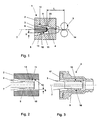
- FIG. 1 shows a schematic representation of an air spinning device 1 with a nozzle body 2, a spindle 3, a fiber guide element 4 and a pair of rollers 5.
- the spindle 3 is hollow and comprises a Garn arrangementskanal 6 which opens into a spindle opening 9 at the spindle tip 8.
- a sliver 14 is fed via a fiber guide element 4 of the spindle opening 9.
- Through holes 20 air is introduced in the direction of the spindle tip 8 in the nozzle body 2.
- the bores are arranged in such a way that a vortex flow results at the spindle tip 8, which detects a part of the fibers from the sliver and moves over the spindle tip 8.
- the introduced air is discharged via a discharge channel 13 of the spindle tip 8 along, wherein the air flow moves around the spindle tip 8 around.
- the discharge channel 13 is formed by the outer surface 11 of the spindle tip 8 and the inner surface 12 of the nozzle body 2.
- the discharge channel 13 has due to the geometry of the spindle tip 8 and the interior of the nozzle body 2 has an annular cross-section.
- the annular cross section has a constant gap width S around the spindle tip 8 normal to the longitudinal axis 7 of the spindle 3.
- the fibers 10 placed around the spindle tip 8 are moved helically about the spindle tip 8 by the rotating air flow.
- the spindle tip 8 is that part of the spindle 3, around which the folded fibers 10 rotate.
- the removal of the air beyond this region of the spindle 3 no longer has any direct influence on the movement of the fibers 10.
- the second end of the fibers 10 is caught in the core fibers, which pass directly into the spindle opening 9 from the fiber guiding element 4. Thereby, the folded fibers 10 are drawn into the spindle opening 9, whereby they wind around the core fibers due to the rotating air flow.
- the distance L between the pair of rollers 5 and the spindle tip 8 and the spindle opening 9 has a significant influence on the number of Umwindemaschinen 10 which are formed by the fluidized air.
- FIG. 2 shows a section of a nozzle body 2 with a projecting into the nozzle body 2 spindle 3 with a spindle tip 8.
- a plurality of annular beads 15 formed on the spindle tip 8.
- the beads 15 shown are shown by way of example with a symmetrical round shape. However, it is also possible to choose angular shapes, and a symmetrical arrangement is not mandatory.
- the limited by the inner surface 12 of the nozzle body 2 and the outer surface 11 of the spindle tip 8 discharge channel 13 has an annular cross-section.
- the gap width S is smaller at these bottlenecks than in each case before or after a bead 15.
- the air flow moving helically in the discharge channel 13 in the direction of the longitudinal axis 7 is influenced by the bottlenecks.
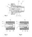
- FIG. 3 shows a further embodiment of the air-spinning device according to the invention.
- the nozzle body 2 is different from FIG. 2 formed in two parts, wherein the discharge channel 13 is limited by the inner surface of a nozzle body insert 17.
- the use of a nozzle body insert 17 allows easy replacement of a highly stressed component without having to change the entire nozzle body 2. It is also possible in the same nozzle body 2 different nozzle body inserts 17 to install alternately.
- the spindle tip 8 is cylindrical with a flat surface.
- the inside of the nozzle body 17 is provided with trapezoidal bulges 16 which project annularly into the interior of the nozzle body insert 17. Through the bulges 16 13 bottlenecks are created in the discharge channel.
- the trapezoidal shape of the bulges causes the air flow at the edge projecting into the discharge channel 13 to break off and form vortices whose axis of rotation is approximately normal to the longitudinal axis 7 of the spindle 3.
- FIG. 4 shows a combination of the embodiments of FIGS. 2 and 3 ,
- Ablasskanal 13 are created by annular bulges 16 in the nozzle body insert 17 and by annular beads 15 at the spindle tip bottlenecks.
- the beads 15 and the bulges 16 need not be attached to the same stiffness in the course of the longitudinal axis 7 of the spindle 3.
- the spindle 3 is arranged displaceably in its holder relative to the nozzle body 2.
- the spindle 3 can in the direction D the longitudinal axis 7 of the spindle to be moved.
- the adjustment of the position of the spindle tip 8 within the nozzle body insert 17 allows a variation of the conditions in the discharge channel 13 which influence the air flow along the spindle tip 8.
- the departure behavior of the air spinning device can be adjusted to the properties and composition of the fiber slivers to be spinned by changing the flow conditions in the discharge channel, without having to replace spindle tip 8 or nozzle body insert 17.
- FIG. 5 shows the embodiment of the FIG. 2 with a two-part spindle 3.
- a spindle tip sleeve 18 is attached.
- the beads 15 which create the bottlenecks in the discharge channel are not directly mounted on the spindle tip 8 in the illustrated two-part embodiment of the spindle 3, but on the outer surface of a spindle tip sleeve 18.
- the spindle tip sleeve 18 is easily interchangeable as a wear part. In an exchange of the spindle tip sleeve 18, however, it is also possible to choose a spindle tip sleeve 18, which has a different design of the annular beads 15 on its outer side.
- the spindle tip sleeve is attached to the spindle tip 8. Due to the air currents in the discharge channel no further connection between the spindle tip 8 and spindle tip sleeve 18 is necessary.
- the spindle tips sleeve can also be attached by other fastening methods on the spindle tip 8, for example by a screw, a pressing or gluing method, a positive connection, a snap connection or by magnetic forces.
- FIG. 6 also shows the embodiment of the FIG. 2 wherein additionally on the inside 12 of the nozzle body 2 bulges 16 were introduced.
- the projecting into the interior of the nozzle body 2 bulges 16 are formed in the form of rings with a rectangular cross-section.
- beads 15 creates a discharge channel 13 in the form of a labyrinth.
- FIG. 6 also shows that the bottlenecks created by beads 15 and bulges 16 in the discharge channel 13 may have a small extension in the direction of the longitudinal axis 7 of the spindle 3 in relation to the length of the spindle tip 8.
- the built-in rings are shown schematically, one Design of fluidically favorable embodiments of beads 15 and bulges 16 is carried out by the person skilled in the art and is not taken into account in the illustration.
- FIG. 7 also shows the embodiment of the FIG. 2 In addition, a Garn arrangements vom 19 is shown.
- the inner diameter of a spindle 3, or the dimensions of the Garn enclosureskanals 6 a spindle 3 is dependent on various factors, such as the properties and composition of the fiber material to be spinned or the desired yarn quality or the rotation of the yarn to be produced.
- the design of the discharge channel 13 can be additionally influenced by the use of spindle tip sleeves, nozzle body inserts or the change in the position of the spindle tip 8 in the nozzle body, a simple adjustment of the dimensions of the Garn entryskanals 6 is advantageous. Such adjustment is possible through the use of Garn Operationssein accountsn 19.
- a yarn guide insert 19 is inserted through the spindle opening in the yarn guide channel 6 of the spindle 3.
- the positioning of the Garn entriessnices 19 in Garn entryskanal 6 can be done by a simple stop 21.
- Such a stop 21 may for example be formed on the spindle 3 or formed by a Seeger ring used.
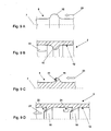
- FIG. 8 shows various embodiments of a design of the spindle tip 8 according to the invention.
- the four spindle tips 8 shown are arbitrary with the in the FIGS. 2 to 6 shown configurations of the inner surfaces of the nozzle body respectively nozzle body inserts can be combined to form a discharge channel.
- the four illustrated spindle tips 8 have various annular beads 15 formed. However, the beads 15 can also by Spindelspitzenhülsen after the FIG. 5 be formed.
- a bead 15 is arranged in the vicinity of the spindle opening 9, it being noted that immediately at the location of the spindle opening 9, the outer diameter of the spindle tip is smaller than at the point the largest extent of the annular bead 15. As a result, a bottleneck is not formed directly on the spindle opening 9 in the air spinning device.
- FIG. 9 shows a schematic representation of various exemplary forms of bulges respectively beads on the inner surfaces of the nozzle body or the outer surfaces of the spindle tips.
- FIGS. 9A to 9D is in each case indicated by the arrow 23, the Garnlaufraum. Under the Garnlaufraum is that direction to understand in which the yarn during operation through the Garn Adjustskanal along the longitudinal axis 7 of the spindle runs.
- FIGS. 9A and 9C show detail sections of the spindle tips.
- Figure 9A shows a spindle tip 8 with a longitudinal axis 7 and a molded bead 15.
- the bead 15 is formed in a symmetrical shape like a wave. In this case, in symmetrical design, the Garnlaufraum 23 plays no role.
- FIG. 9C In contrast, a bead 15 is shown with an undercut 22. In this case, the yarn running direction 23 is important, since the desired backflow with the vortex formation does not occur to the desired extent on flow of the bead from the wrong side.
- FIGS. 9B and 9D show detail sections of the nozzle body 2 in a sectional view, so that the inner surface 12 of the nozzle body 2 can be seen.
- FIG. 9B shows a nozzle body 2 with an asymmetric bulge 16. The bulge 16 is in the yarn running direction 23 first rising obliquely to then drop steeply. Such an arrangement promotes the formation of a backflow to aid in the incorporation of short fibers into the forming yarn in the spindle tip.
- FIG. 9D shows a nozzle body 2 with two consecutive edged bulges 16th
Description
Die Erfindung betrifft eine Luftspinnvorrichtung mit einer Spindel gemäss dem Oberbegriff der unabhängigen Ansprüche.The invention relates to an air spinning device with a spindle according to the preamble of the independent claims.
Als Luftspinnvorrichtung im Sinne der Erfindung ist eine Garnspinnvorrichtung oder eine Vorgarnspinnvorrichtung zu verstehen, wobei die vorgeschlagene Vorrichtung für alle Spinnverfahren welche mit Luft arbeiten einsetzbar ist.As an air-spinning device in the context of the invention, a yarn spinning device or a roving spinning device is to be understood, wherein the proposed device for all spinning processes which work with air can be used.
Eine Spinnvorrichtung welche dazu dient, mit Hilfe eines Luftstromes ein Garn herzustellen, umfasst eine Faserbandzuführung, ein Streckwerk, eine Luftspinnvorrichtung und eine Aufwickeleinrichtung. Von der Faserbandzuführung wird ein Faserband von einem vorgelegten Faserbandspeicher zu einem Streckwerk geführt. Im Streckwerk wird das Faserband unter einem bestimmten Verzug verstreckt und an die Luftspinnvorrichtung weitergegeben. In der Luftspinnvorrichtung wird das verstreckte Faserband über ein Faserführungselement einer Wirbelzone zugeführt. Die Wirbelzone ist ein Raum zwischen dem Faserführungselement und der Eintrittsöffnung in eine dem Faserführungselement gegenüberliegenden Spindel. Die Wirbelzone ist in einem Düsenkörper angeordnet in welchen von der einen Seite das Faserführungselement und von der gegenüberliegenden Seite eine Spindel eingefügt sind. In die Wirbelzone wir durch entsprechend angeordnete Bohrungen Druckluft eingebracht, welche durch die Anordnung der Bohrungen zur Bildung eines Wirbels führt, der aussen an der Spindel entlang abgeführt wird. Durch die Wirbelströmung der eingebrachten Druckluft wird ein Teil der Fasern des in die Luftspinnvorrichtung eingebrachten Faserbandes aus dem Faserband herausgelöst und um die Spindelspitze herum umgelegt. Dabei bleiben die Faserenden in den nicht herausgelösten Fasern des Faserbandes gefangen und werden mit diesen sogenannten Kernfasern in die Spindel hineingezogen. Während des Hineinziehens dieser herausgelösten Fasern, auch Umwindefasern genannt, in die Spindelöffnung werden die Umwindefasern aufgrund der Wirbelströmung um die Kernfasern herumgewunden. Durch die Konstruktion der einzelnen Bauteile und die Einstellungen der Wirbelluft können verschiedene Eigenschaften des Spinnvorganges beeinflusst werden. Beispielsweise kann die Anzahl der Umwindefasern im Verhältnis zu den Kernfasern verändert werden oder die Anzahl der Umwindungen pro Länge oder die Garndrehung des fertigen Garns kann eingestellt werden. Unter der Garndrehung ist der Winkel zu verstehen unter welchem die Umwindefasern im Verhältnis zur Längsachse des Garns die Kernfasern umschlingen. Auf diese Art und Weise ist es möglich Garne mit unterschiedlichen Eigenschaften im Luftspinnverfahren herzustellen, beispielsweise auch Vorgarn. Unter Vorgarn versteht man ein Zwischenprodukt welches als Ausgangsprodukt für Endspinnverfahren, wie beispielsweise Ringspinnen oder Rotorspinnen, verwendet wird. Bei der Herstellung von Vorgarn ist es wichtig, dass die Garndrehung einerseits derart gering ist, dass sie im Endspinnverfahren wieder aufgelöst werden kann und andrerseits genügend gross ist um einen sicheren Transport und eine störungsfreie Zuführung zur Endspinnvorrichtung zu gewährleisten.A spinning device which serves to produce a yarn by means of an air flow comprises a sliver feed, a drafting device, an air spinning device and a take-up device. From the sliver feeder, a sliver is fed from a fiber sliver storage presented to a drafting system. In the drafting system, the sliver is stretched under a certain delay and passed on to the air spinning device. In the air spinning device, the stretched sliver is fed via a fiber guide element of a vortex zone. The vortex zone is a space between the fiber guide element and the inlet opening in a spindle opposite the fiber guide element. The vortex zone is arranged in a nozzle body in which the fiber guide element is inserted from one side and a spindle from the opposite side. Into the vortex zone we introduce compressed air through correspondingly arranged holes, which through the arrangement of the bores leads to the formation of a vortex, which is discharged outside along the spindle. Due to the turbulence of the introduced compressed air, a part of the fibers of the introduced into the air spinning device sliver is removed from the sliver and folded around the spindle tip around. The fiber ends are trapped in the non-dissolved fibers of the sliver and are drawn into the spindle with these so-called core fibers. During the pulling of these dissolved fibers, also called Umwindefasern, in the spindle opening, the Umwindefasern be wound around the core fibers due to the vortex flow. Due to the design of the individual components and the settings of the vortex air, various properties of the spinning process can be influenced. For example, the number of wraps compared to the core fibers may be changed, or the number of wraps per length or yarn twist of the finished yarn can be adjusted. Under the yarn twist is the angle to understand under which the Umwindefasern in relation to the longitudinal axis of the yarn wrap around the core fibers. In this way, it is possible to produce yarns with different properties in the air spinning process, for example, roving. By roving is meant an intermediate which is used as a starting material for final spinning processes, such as ring spinning or rotor spinning. In the production of roving, it is important that the yarn twist on the one hand is so low that it can be dissolved in Endspinnverfahren again and on the other hand is large enough to ensure safe transport and trouble-free feeding to Endspinnvorrichtung.
Aus dem Stand der Technik sind verschiedene Arten von Luftspinnvorrichtungen bekannt. Die
Die Aufgabe der Erfindung ist es, die Nachteile des Standes der Technik zu vermeiden und eine Luftspinnvorrichtung zu schaffen, welche eine Minimierung des Abganges und damit eine bessere Rohstoffausnutzung ermöglicht und eine Einstellung der Garndrehung vereinfacht.The object of the invention is to avoid the disadvantages of the prior art and to provide an air spinning device which allows minimization of the departure and thus a better utilization of raw materials and simplifies adjustment of the yarn rotation.
Die Lösung der Aufgabe erfolgt durch eine Luftspinnvorrichtung mit den kennzeichnenden Merkmalen der unabhängigen Ansprüche. Die Aufgabe wird dadurch gelöst, dass eine Luftspinnvorrichtung mit einem Düsenkörper und einer hohlen Spindel mit einer Spindelspitze und einer Längsachse vorgesehen ist, wobei die Spindelspitze in den Düsenkörper hineinragt und sich zwischen einer Aussenfläche der Spindelspitze und einer Innenfläche des Düsenkörpers ein Ablasskanal mit einer ringförmigen Querschnittsfläche bildet und eine normal zur Längsachse der Spindel gesehene Spaltweite an einer bestimmten Stelle des Ablasskanals über den Umfang der Spindel konstant ist. Dabei sind die Aussenfläche der Spindelspitze und/oder die Innenfläche des Düsenkörpers derart geformt ist, dass im Ablasskanal in seinem Verlauf in Richtung der Längsachse der Spindel zumindest zwei Engstellen im Ablasskanal gebildet wird, wobei der Ablasskanal in seinem Verlauf in Richtung der Längsachse der Spindel an jeder dieser Engstellen eine ringförmige Querschnittsfläche aufweist, die kleiner ist als die ringförmige Querschnittsfläche des Ablasskanals vor und nach jeder dieser zumindest zwei Engstellen.The object is achieved by an air spinning device with the characterizing features of the independent claims. The object is achieved in that an air spinning device is provided with a nozzle body and a hollow spindle with a spindle tip and a longitudinal axis, wherein the spindle tip protrudes into the nozzle body and between a outer surface of the spindle tip and an inner surface of the nozzle body, a drain channel with an annular cross-sectional area forms and a normal to the longitudinal axis of the spindle seen gap width at a certain point of the discharge channel over the circumference of the spindle is constant. In this case, the outer surface of the spindle tip and / or the inner surface of the nozzle body is shaped such that in the discharge channel in its course in the direction of the longitudinal axis of the spindle at least two bottlenecks in the discharge channel is formed, the discharge channel in its course in the direction of the longitudinal axis of the spindle each of these constrictions has an annular cross-sectional area that is smaller than the annular cross-sectional area of the bleed passage before and after each of these at least two constrictions.
Die Erfindung ist grundsätzlich auf jeder Luftspinnmaschine einsetzbar, unabhängig von der Art des herzustellenden Garns oder Vorgarns, bei der mindestens ein Teil der Fasern im Querschnitt des Verfahrensprodukts eine Drehung besitzt und die Maschine daher eine Luftspinnvorrichtung mit einer hohlen Spindel und einem Düsenkörper aufweist.The invention is basically applicable to any air-spinning machine, irrespective of the type of yarn or roving to be produced, in which at least part of the fibers in the cross-section of the process product has a rotation and the machine therefore has an air-spinning device with a hollow spindle and a nozzle body.
Beim Luftspinnen zur Herstellung eines Garns oder Vorgarns durch Umwindung von Kernfasern mit Umwindefasern werden Luftspinnvorrichtungen eingesetzt, welche eine hohle Führungsspindel und einen Düsenkörper umfassen. In der Spindel ist ein Garnführungskanal vorgesehen, welcher mit einer Spindelöffnung in der Spindelspitze mündet. Ein zu verspinnendes Faserband wird über ein der Spindel vorgelagertes Faserführungselement in den Düsenkörper eingebracht. Die Spindel ragt mit ihrer Spitze in den Düsenkörper hinein, wobei sich zwischen einer Aussenfläche der Spindelspitze und einer Innenfläche des Düsenkörpers ein Ablasskanal mit einer ringförmigen Querschnittsfläche bildet. Zwischen dem Faserführungselement und der Spindelspitze wird eine Wirbelzone ausgebildet. Durch entsprechend angeordnete Bohrungen wird Druckluft in die Wirbelzone eingedüst, die aufgrund der Anordnung der Bohrungen eine Wirbelströmung ergibt. Die Druckluft wird aus der Wirbelzone über den Ablasskanal abgeführt, wobei sich eine der Spindel entlangführende drehende Luftströmung ergibt. Die durch das Faserführungselement in die Luftspinnvorrichtung eingebrachten Fasern werden durch die Wirbelströmung in Kernfasern, Umwindefasern und Abgang aufgeteilt, wobei die Kernfasern direkt in die Spindelöffnung eingebracht werden, die Umwindefasern mit einem Ende in den Kernfasern gefangen und mit einem anderen Ende über die Spindelspitze umgelegt werden und der Abgang durch die der Spindel entlangführende Luftströmung aus der Luftspinnvorrichtung ausgebracht wird. Die um die Spindelspitze gelegten Fasern bewegen sich schraubenlinienförmig um die Spindelspitze und bilden eine sogenannte Fasersonne. Als Spindelspitze wird derjenige Bereich der Spindel bezeichnet, in welchem sich die umgelegten Fasern bewegen. Die über diesen Bereich der Spindel hinaus gehende Abführung der Luft hat keinen direkten Einfluss mehr auf die Bewegung der Fasern. Die Anzahl der Umwindefasern wird bestimmt durch den Abstand der Spindelspitze von einem letzten Klemmpunkt des Faserbandes. Das Faserband wird vor dem Erreichen des Faserführungselementes durch ein Rollenpaar geführt welches einen Klemmpunkt bildet. Aufgrund der Länge der einzelnen Fasern wird der Abstand zwischen diesem Klemmpunkt und der Spindelspitze gewählt. Bei gleichbleibender Faserlänge erhöht sich der Anteil der Umwindefasern mit einer Vergrösserung des Abstandes zwischen Klemmpunkt und Spindelspitze. Diese Erhöhung der Anzahl Umwindefasern bewirkt aber gleichzeitig eine Erhöhung des Abganges. Durch eine. Verengung des Ablasskanals kann der Abgang wiederum vermindert werden, was sich jedoch nachteilig auf die Verwirbelung der Umwindefasern auswirkt.In air spinning for making a yarn or roving by wrapping core fibers with wraps, air spinning devices are used which comprise a hollow guide spindle and a nozzle body. In the spindle a Garnführungskanal is provided, which opens with a spindle opening in the spindle tip. A fiber sliver to be spun is introduced into the nozzle body via a fiber guide element arranged upstream of the spindle. The spindle protrudes with its tip into the nozzle body, wherein a discharge channel with an annular cross-sectional area forms between an outer surface of the spindle tip and an inner surface of the nozzle body. Between the fiber guide element and the spindle tip, a vortex zone is formed. By appropriately arranged holes compressed air is injected into the vortex zone, which results in a vortex flow due to the arrangement of the holes. The compressed air is removed from the vortex zone via the discharge channel, resulting in a rotating air flow along the spindle. The fibers introduced into the air-spinning device by the fiber guiding element are divided by the turbulent flow into core fibers, sheath fibers and fibers, the core fibers being introduced directly into the spindle opening, the sheath fibers being trapped at one end in the core fibers and transferred at the other end via the spindle tip and the outlet is discharged from the air spinning device through the airflow passing the spindle. The fibers placed around the spindle tip move helically around the spindle tip and form a so-called fiber sun. The spindle tip is that region of the spindle in which the transferred fibers move. The removal of air beyond this area of the spindle has no direct influence on the movement of the fibers. The number of Umwindefasern is determined by the distance of the spindle tip of a last terminal point of the sliver. The sliver is passed before reaching the fiber guide element by a pair of rollers which forms a terminal point. Due to the length of the individual fibers, the distance between this clamping point and the spindle tip is selected. With a constant fiber length, the proportion of Umwindefasern increases with an increase in the distance between the clamping point and the spindle tip. However, this increase in the number of Umwindefasern simultaneously causes an increase in the departure. By a. Narrowing of the discharge channel, the outlet can be reduced again, but this has a detrimental effect on the turbulence of Umwindefasern.
Nach der Erfindung ist der Ablasskanal in seiner geometrischen Form derart gestaltet, dass sich im Abgang befindliche Fasern durch die Umwindefasern vor dem Ausbringen gefangen und in das Garn oder Vorgarn eingebracht werden. Dies hat den Vorteil, dass der Abgang vermindert wird ohne die Verwirbelung der Umwindefasern zu beeinflussen. Die Form des Ablasskanals verändert den Umlauf der Fasern um die Spindelspitze. Über die Länge der Fasern betrachtet unterliegen einzelne Abschnitte der Fasern aufgrund der Gestaltung des Ablasskanals Beschleunigungen, Verlangsamungen oder Verwirbelungen in ihrer rotierenden schraubenförmigen Bewegung. Die Art der Bewegungen, welche durch die Fasern um die Spindelspitze erfolgt beeinflusst auch die Garndrehung. Durch eine Verringerung der Umlaufgeschwindigkeit ergibt sich eine geringere Drehung, wobei die Luft- und Strömungsverhältnisse in der Wirbelzone nicht verändert werden müssen, beispielsweise durch eine Verringerung der Wirbelluft.According to the invention, the drainage channel is designed in its geometric shape such that fibers located at the exit are caught by the wraparound fibers prior to deployment and introduced into the yarn or roving. This has the advantage that the finish is reduced without affecting the turbulence of the Umwindefasern. The shape of the discharge channel changes the circulation of the fibers around the spindle tip. Viewed along the length of the fibers, individual sections of the fibers are subject to accelerations, decelerations or swirls in their rotating helical motion due to the design of the bleed channel. The nature of the movements made by the fibers around the spindle tip also affects the yarn twist. By reducing the rotational speed results in a lower rotation, the air and flow conditions in the vortex zone must not be changed, for example by reducing the fluidizing air.
In einer ersten Ausführungsform umfasst die Luftspinnvorrichtung einen Düsenkörper und eine hohle Spindel mit einer Spindelspitze und einer Längsachse, wobei die Spindelspitze in den Düsenkörper hineinragt und sich zwischen einer Aussenfläche der Spindelspitze und einer Innenfläche des Düsenkörpers ein Ablasskanal mit einer ringförmigen Querschnittsfläche bildet. Eine normal zur Längsachse der Spindel gesehene Spaltweite an einer bestimmten Stelle des Ablasskanals ist über den Umfang der Spindel konstant. Die Aussenfläche der Spindelspitze ist derart geformt ist, dass im Ablasskanal in seinem Verlauf in Richtung der Längsachse der Spindel zumindest zwei Engstellen gebildet werden, wobei der Ablasskanal in seinem Verlauf in Richtung der Längsachse der Spindel an jeder dieser Engstellen eine ringförmige Querschnittsfläche aufweist, die kleiner ist als die ringförmige Querschnittsfläche des Ablasskanals vor und nach jeder dieser zumindest zwei Engstellen. Die Innenfläche des Düsenkörpers ist zylindrisch ausgeformt, sodass sich über den Umfang der Spindel an jeder Stelle des Ablasskanals die gleiche Spaltweite ergibt und ein ringförmiger Querschnitt entsteht. Durch die geschaffenen Engstellen im Ablasskanal wird das Strömungsbild der abfliessenden Wirbelluft beeinflusst. Die Engstellen erzeugen eine Veränderung der Verwirbelung der abfliessenden Luft. Die Geschwindigkeit der abfliessenden Luft wird durch die Engstellen beeinflusst. Die Geschwindigkeit wird vor einer Engstelle verringert, durch die Verengung des Ablasskanals erhöht und durch die nachfolgende Erweiterung des Ablasskanals wieder verringert. Durch die Schaffung einer Abreisskante aufgrund der Formgebung an der Engstelle können Rückströmungen oder Wirbel welche normal zur Luftströmung entlang der Spindel drehen, erzeugt werden, was zusätzlich zur Verminderung des Abganges beiträgt.In a first embodiment, the air spinning device comprises a nozzle body and a hollow spindle with a spindle tip and a longitudinal axis, wherein the spindle tip protrudes into the nozzle body and forms an outlet channel with an annular cross-sectional area between an outer surface of the spindle tip and an inner surface of the nozzle body. A gap width seen normal to the longitudinal axis of the spindle at a certain point of the discharge channel is constant over the circumference of the spindle. The outer surface of the spindle tip is shaped such that in the discharge channel in its course in the direction of the longitudinal axis of the spindle at least two bottlenecks are formed, wherein the discharge channel in its course in the direction of the longitudinal axis of the spindle at each of these bottlenecks has an annular cross-sectional area, the smaller is as the annular cross-sectional area of the discharge channel before and after each of these at least two bottlenecks. The inner surface of the nozzle body is cylindrically shaped, so that over the circumference of the spindle at each point of the discharge channel results in the same gap width and an annular cross section is formed. Through the bottlenecks created in the discharge channel, the flow pattern of the flowing fluidized air is influenced. The bottlenecks produce a change in the turbulence the outflowing air. The speed of the outflowing air is influenced by the bottlenecks. The speed is reduced before a constriction, increased by the narrowing of the discharge channel and reduced again by the subsequent expansion of the discharge channel. By creating a tear-off edge due to the shape at the throat, backflows or vortices that normally rotate with the air flow along the spindle can be created, which also contributes to the reduction of the outlet.
Die Bildung der Rückströmungen nach einer Engstelle wird durch eine zweite nachfolgende Engstelle verstärkt. Die Rückströmung und der dadurch entstehende Wirbel bewirken, dass die Fasern welche normalerweise als Abgang der Spindel entlang abgeführt werden zumindest teilweise gegen die Spindel gedrückt werden. In der Nähe der Spindelaussenfläche werden diese Fasern durch die sich in der Fasersonne befindenden Fasern gefangen und in das Garn eingebunden. Die durch die Rückströmungen entstehenden Wirbel drehen sich um eine Achse, welche im wesentlichen senkrecht zur Achse der Spindel steht und sich auf einem zur Innenkontur des Düsenkörpers konzentrischen Kreis befindet. Der Wirbel dreht einerseits in sich selbst und andrerseits wird der Wirbel kreisförmig, durch den die Fasersonne drehenden Luftstrom, um die Spindel gedreht.The formation of backflow to a bottleneck is enhanced by a second subsequent bottleneck. The backflow and the resulting vortex cause the fibers, which are normally discharged along the spindle, to be at least partially pressed against the spindle. Near the spindle outer surface, these fibers are caught by the fibers in the fiber sun and incorporated into the yarn. The vortexes created by the backflows rotate about an axis which is substantially perpendicular to the axis of the spindle and is located on a circle concentric with the inner contour of the nozzle body. The vortex turns on the one hand in itself and on the other hand, the vortex is circular, rotated by the fiber sun rotating air flow to the spindle.
Die Bildung einer Engstelle kann dadurch erfolgen, dass an der Aussenfläche der Spindelspitze ein ringförmiger Wulst vorgesehen wird. Die Ausbildung des Wulstes ist in seiner geometrischen Form nur dadurch eingeschränkt, dass die genannte Querschnittsfläche über den Umfang der Spindel eine gleichmässige Spaltweite ergibt. Der angeformte Wulst kann rund, respektive wellenförmig, sein oder auch Kanten aufweisen. Bei einer Ausführung mit mehreren Engstellen können diese durch mehrere Wülste gebildet werden, wobei sich die Wülste durch verschiedene geometrische Formen wie auch verschiedenen Dimensionen unterscheiden können.The formation of a constriction can be effected by providing an annular bead on the outer surface of the spindle tip. The formation of the bead is limited in its geometric form only in that the said cross-sectional area over the circumference of the spindle results in a uniform gap width. The molded bead can be round, wavy, or even have edges. In a design with multiple bottlenecks, these can be formed by a plurality of beads, wherein the beads can differ by different geometric shapes as well as different dimensions.
Zur Förderung der Bildung der Rückströmungen, respektive der Wirbelströme normal zur Spindelachse, eignen sich beispielsweise asymmetrische Wellenformen oder Wulste, respektive Ausbuchtungen, welche in Richtung des Garnverlaufs mit einem Hinterschnitt versehen sind.To promote the formation of the return flows, respectively the eddy currents normal to the spindle axis, asymmetrical waveforms or beads, respectively bulges, which are provided in the direction of the yarn course with an undercut, are suitable, for example.
Bevorzugterweise ist die Spindel zweiteilig ausgeführt. Dabei bildet die Spindelspitze mit dem daran ausgeformten Wulst einen ersten Teil der Spindel und ist am zweiten Teil der Spindel anbringbar. Unter anbringbar ist zu verstehen, dass der erste und der zweite Teil der Spindel passgenau an einer Kontaktstelle aufeinander abgestimmt sind. Die Teile der Spindel können dabei ohne die Schaffung einer mechanischen oder chemischen Verbindung an der Kontaktstelle zusammengefügt werden. Aufgrund der im Düsenkörper herrschenden Druckverhältnisse werden die beiden Teile der Spindel zusammengehalten. Weiter kann auch eine mechanische Verbindung des ersten mit dem zweiten Teil der Spindel vorgesehen werden, dies kann beispielsweise eine Steck- oder Schraubverbindung sein. In einer weiteren Ausführung wird der erste Teil der Spindel durch die Aussenfläche der Spindelspitze gebildet, wobei dieser auf dem zweiten Teil der Spindel anbringbar ist, beispielsweise in Form einer Spindelspitzenhülse. Die Befestigung kann dabei durch Aufstecken oder eine andere Art der Befestigung, beispielsweise Schrauben, erfolgen. Der Vorteil der zweiteiligen Ausführung liegt in einer einfachen Austauschbarkeit des Teils einer Spindel welches dem grössten Verschleiss unterworfen ist. Zusätzlich ergibt sich die Möglichkeit die Form der Aussenfläche der Spindelspitze zu wechseln, ohne die gesamte Spindel austauschen zu müssen. Gleichzeitig mit dem Austausch der Spindelspitze ist eine Veränderung der Wirbelzone möglich, wenn die Spindelspitze beispielsweise tiefer in den Düsenkörper hineinragt als die ausgewechselte Spindelspitze.Preferably, the spindle is designed in two parts. In this case, the spindle tip forms with the bead formed thereon a first part of the spindle and can be attached to the second part of the spindle. Under attachable is to be understood that the first and the second part of the spindle are precisely matched to one another at a contact point. The parts of the spindle can be assembled without the creation of a mechanical or chemical compound at the contact point. Due to the pressure conditions prevailing in the nozzle body, the two parts of the spindle are held together. Further, a mechanical connection of the first with the second part of the spindle can be provided, this may for example be a plug or screw connection. In a further embodiment, the first part of the spindle is formed by the outer surface of the spindle tip, which can be attached to the second part of the spindle, for example in the form of a spindle tip sleeve. The attachment can be done by attaching or another type of attachment, such as screws. The advantage of the two-part design lies in a simple interchangeability of the part of a spindle which is subjected to the greatest wear. In addition, there is the possibility of changing the shape of the outer surface of the spindle tip, without having to replace the entire spindle. Simultaneously with the replacement of the spindle tip a change in the vortex zone is possible if the spindle tip, for example, extends deeper into the nozzle body than the replaced spindle tip.
Es hat sich gezeigt, dass für die konstruktive Ausführung des Wulstes oder der Summe der Wülste ein Verhältnis eines grössten Aussendurchmessers des Wulstes zu einem kleinsten Aussendurchmesser der Spindelspitze bevorzugt 1,05 bis 1,5 beträgt.It has been shown that, for the structural design of the bead or the sum of the beads, a ratio of a maximum outside diameter of the bead to a smallest outside diameter of the spindle tip is preferably 1.05 to 1.5.
In einer zweiten Ausführungsform wird die Spindelspitze in einer zylindrischen Form ausgebildet und die Innenfläche des Düsenkörpers derart geformt, dass im Ablasskanal in seinem Verlauf in Richtung der Längsachse der Spindel zumindest zwei Engstellen gebildet werden, wobei der Ablasskanal in seinem Verlauf in Richtung der Längsachse der Spindel an jeder dieser Engstellen eine ringförmige Querschnittsfläche aufweist, die kleiner ist als die ringförmige Querschnittsfläche des Ablasskanals vor und nach jeder dieser zumindest zwei Engstellen. Die Engstelle kann durch eine Ausbuchtung im Düsenkörper gebildet werden, welche ringförmig in den Innenraum des Düsenkörpers hineinragt. Auch für die Ausführung einer solchen Ausbuchtung sind verschiedene geometrische Formen denkbar. Die angeformte Ausbuchtung kann rund sein oder auch Kanten aufweisen. Bei einer Ausführung mit mehreren Engstellen können diese durch mehrere Ausbuchtungen gebildet werden, wobei sich die Ausbuchtungen durch verschiedene geometrische Formen wie auch verschiedenen Dimensionen unterscheiden können. Der Düsenkörper kann auch zweiteilig ausgeführt sein, wobei die Innenfläche des Düsenkörpers durch einen Düsenkörpereinsatz gebildet ist und dieser in den Düsenkörper einbringbar ist.In a second embodiment, the spindle tip is formed in a cylindrical shape and the inner surface of the nozzle body is formed such that in the discharge channel in its course in the direction of the longitudinal axis of the spindle at least two bottlenecks are formed, wherein the discharge channel in its course in the direction of the longitudinal axis of the spindle at each of these constrictions has an annular cross-sectional area which is smaller than the annular cross-sectional area of the discharge passage before and after each of these at least two bottlenecks. The constriction can be formed by a bulge in the nozzle body, which projects annularly into the interior of the nozzle body. Also for the execution of such a bulge various geometric shapes are conceivable. The formed bulge may be round or have edges. In a design with multiple bottlenecks, these can be formed by a plurality of protrusions, wherein the bulges can differ by different geometric shapes as well as different dimensions. The nozzle body can also be designed in two parts, wherein the inner surface of the nozzle body is formed by a nozzle body insert and this can be introduced into the nozzle body.
Durch eine Veränderung der Lage des Düsenkörpers zur Spindel in Richtung der Längsachse der Spindel können die Bildung sowie die Grösse von Engstellen innerhalb des Ablasskanals eingestellt werden. Dadurch, dass die Spindel oder der Düsenkörper in Richtung der Längsachse der Spindel bewegbar ist, ist der Ablasskanal in seiner Form entlang der Spindelspitze einstellbar. Durch einen in der Längsachse der Spindel beweglichen Düsenkörper wird derselbe Effekt erzielt, da die relative Verschiebung von Spindel und Düsenkörper gegeneinander zu einer Änderung der Einstellung führt. So kann beispielsweise mit einer Vergrösserung der Entfernung der Spindel mit der Spindelöffnung vom Faserführungselement eine Vergrösserung der Wirbelzone geschaffen werden. Gleichzeitig kann dabei die Spaltweite verkleinert werden, wenn sich an der Spindelspitze befindliche Wülste mit an der Innenfläche des Düsenkörpers angebrachten Ausbuchtungen in Übereinstimmung gebracht werden. Die gleichen Einstellungen können erreicht werden durch einen Austausch einer Spindelspitzenhülse oder eines Düsenkörpereinsatzes.By changing the position of the nozzle body to the spindle in the direction of the longitudinal axis of the spindle, the formation and the size of bottlenecks within the discharge channel can be adjusted. Characterized in that the spindle or the nozzle body is movable in the direction of the longitudinal axis of the spindle, the discharge channel is adjustable in shape along the spindle tip. By a moving in the longitudinal axis of the spindle nozzle body, the same effect is achieved because the relative displacement of the spindle and nozzle body against each other leads to a change in the setting. Thus, for example, an enlargement of the distance between the spindle and the spindle opening of the fiber guide element can be used to increase the vortex zone. At the same time, the gap width can be reduced, if beads located on the spindle tip are brought into conformity with bulges attached to the inner surface of the nozzle body. The same settings can be achieved by replacing a spindle tip sleeve or a nozzle body insert.
Auch eine Kombination der ersten mit der zweiten Ausführungsform ist denkbar. Die Gestaltung der Innenfläche des Düsenkörpers und der Aussenfläche der Spindel sind jedoch derart aufeinander abzustimmen, dass die Querschnittsfläche des Ablasskanals ringförmig ist und sich in einer bestimmten Querschnittsfläche eine Spaltweite ergibt, welche über den Umfang der Spindel gleich ist. Eine weitere Ausführung kann erreicht werden, wenn die Ausbuchtungen im Düsenkörper den Innendurchmesser des Düsenkörpers nicht verkleinern, sondern vergrössern. Auch derartige Nuten oder Rillen sind unter dem Begriff Ausbuchtungen zu verstehen, sofern im Zusammenspiel mit der Spindelspitze eine Engstelle des Ablasskanals geschaffen wird.A combination of the first with the second embodiment is conceivable. However, the design of the inner surface of the nozzle body and the outer surface of the spindle are so matched to one another that the cross-sectional area of the discharge channel is annular and results in a certain cross-sectional area a gap width, which is equal over the circumference of the spindle. A further embodiment can be achieved if the bulges in the nozzle body do not reduce the inner diameter of the nozzle body, but increase it. Also such grooves or grooves are Under the term bulges to understand, provided in conjunction with the spindle tip a bottleneck of the discharge channel.
Unabhängig von der Ausführung des Ablasskanals kann durch den Einsatz eines Garnführungseinsatzes in den Garnführungskanal der Spindelspitze der Innendurchmesser des Garnführungskanals verändert werden. Gleichzeitig wird durch einen derartigen Garnführungseinsatz auch die Form der Spindelöffnung veränderbar. Durch die Schaffung von Engstellen im Ablasskanal kann sich eine Rückströmung im Garnführungskanal bilden, was dazu führt, dass Luft entgegen der Garnförderrichtung durch die Spindel in die Wirbelzone gesaugt wird. Entsprechend vermindert sich der Luftstrom welcher entlang dem Faserführungselement in die Wirbelzone gesogen wird. Der dem Faserführungselement entlang strömende Luft ist für die Faserbandauflösung und den Transport des Faserbandes zur Spindelöffnung wichtig. Diesem Umstand kann durch eine Verengung des Garnführungskanals mit dem Einsatz eines Garnführungseinsatzes im Bereich der Spindelspitze Rechnung getragen werden.Regardless of the design of the discharge channel can be changed by the use of a Garnführungseinses in the yarn guide channel of the spindle tip, the inner diameter of Garnführungskanals. At the same time by such Garnführungseinsatz the shape of the spindle opening can be changed. Through the creation of bottlenecks in the discharge channel, a backflow can form in the yarn guide channel, which leads to air being sucked against the yarn conveying direction by the spindle into the vortex zone. Accordingly, the air flow which is sucked along the fiber guide element in the vortex zone decreases. The air flowing along the fiber guiding element is important for the sliver dissolution and the transport of the sliver to the spindle opening. This circumstance can be taken into account by narrowing the yarn guide channel with the use of a Garnführungseinsatzes in the spindle tip.
Im Folgenden wird die Erfindung anhand von beispielhaften Ausführungen erklärt und durch Zeichnungen erläutert:
Figur 1- Schematische Darstellung einer Luftspinnvorrichtung nach dem Stand der Technik
Figur 2- Schematische Darstellung einer erfindungsgemässen Luftspinnvorrichtung in einer ersten Ausführungsform
Figur 3- Schematische Darstellung einer erfindungsgemässen Luftspinnvorrichtung in einer zweiten Ausführungsform
- Figur 4
- Schematische Darstellung einer erfindungsgemässen Luftspinnvorrichtung in einer dritten Ausführungsform
- Figur 5
- Schematische Darstellung einer zweiteiligen Spindelspitze
- Figur 4
- Schematische Darstellung einer erfindungsgemässen Luftspinnvorrichtung in einer vierten Ausführungsform
Figur 7- Schematische Darstellung einer zweiteiligen Spindel
Figur 8- Schematische Darstellung verschiedener Ausführungsformen einer Spindel
Figur 9- Schematische Darstellung verschiedener beispielhafter Formen von Ausbuchtungen respektive Wülsten an Düsenkörper oder Spindel
- FIG. 1
- Schematic representation of an air-spun device according to the prior art
- FIG. 2
- Schematic representation of an inventive air spinning device in a first embodiment
- FIG. 3
- Schematic representation of an inventive air spinning device in a second embodiment
- FIG. 4
- Schematic representation of an inventive air spinning device in a third embodiment
- FIG. 5
- Schematic representation of a two-part spindle tip
- FIG. 4
- Schematic representation of an inventive air spinning device in a fourth embodiment
- FIG. 7
- Schematic representation of a two-part spindle
- FIG. 8
- Schematic representation of various embodiments of a spindle
- FIG. 9
- Schematic representation of various exemplary forms of bulges respectively beads on nozzle body or spindle
In
- 11
- LuftspinnvorrichtungAir spinning device
- 22
- Düsenkörpernozzle body
- 33
- Spindelspindle
- 44
- FaserführungselementFiber guide element
- 55
- Rollenpaarroller pair
- 66
- Garnführungskanalyarn guide
- 77
- Längsachse der SpindelLongitudinal axis of the spindle
- 88th
- Spindelspitzestem tip
- 99
- Spindelöffnungspindle hole
- 1010
- Faserfiber
- 1111
- Aussenfläche der SpindelspitzeOuter surface of the spindle tip
- 1212
- Innenfläche des DüsenkörpersInner surface of the nozzle body
- 1313
- Ablasskanaldrain channel
- 1414
- Faserbandsliver
- 1515
- Wulstbead
- 1616
- Ausbuchtungbulge
- 1717
- DüsenkörpereinsatzNozzle body use
- 1818
- SpindelspitzenhülseSpindle tip sleeve
- 1919
- GarnführungseinsatzGarnführungseinsatz
- 2020
- Bohrungendrilling
- 2121
- Anschlagattack
- 2222
- Hinterschnittundercut
- 2323
- Garnlaufrichtungyarn running
- 2424
- Rückströmungbackwash
- DD
- Bewegung der SpindelMovement of the spindle
- SS
- Spaltweitegap width
- LL
- Abstand zwischen Rollenpaar und SpindelspitzeDistance between roller pair and spindle tip
Claims (14)
- Air spinning device (1) having a nozzle body (2) and a hollow spindle (3) with a spindle tip (8) and a longitudinal axis (7), wherein the spindle tip (8) protrudes into the nozzle body (2) and an outlet channel (13) having a ring-shaped cross-sectional area is formed between an outside surface (11) of the spindle tip (8) and an inside surface (12) of the nozzle body (2), and a gap width (S) at a certain location of the outlet channel (13) as seen normal to the longitudinal axis (7) of the spindle (3) is constant over the circumference of the spindle (3), characterized in that the outside surface (11) of the spindle tip (8) and/or the inside surface (92) of the nozzle body (2) is/are shaped in such a way that at least two constrictions are formed in the outlet channel (13) and its course in the direction of the longitudinal axis (7) of the spindle (3), wherein the outlet channel (13) has a ring-shaped cross-sectional area at each of these constrictions in its course in the direction of the longitudinal axis (7) of the spindle (3), this cross-sectional area being smaller than the ring-shaped cross-sectional area of the outlet channel (13) upstream and downstream from each of these at least two constrictions.
- The air spinning device (1) according to Claim 1, characterized in that at least one ring-shaped bulge (15) is provided on the outside surface (11) of the spindle tip (8).
- The air spinning device (1) according to Claim 1 or 2, characterized in that at least one ring-shaped barreling (16) protruding into the interior is provided on the inside surface (12) of the nozzle body (2).
- The air spinning device (1) according to any ona of Claims 1 to 3, characterized in that the spindle (3) is designed in two parts, wherein the spindle tip (8) is a first part of the spindle and is attachable to the second part of the spindle.
- The air spinning device (1) according to any one of Claims 1 to 3, characterized in that the spindle (3) is designed in two parts, wherein the outside surface (11) of the spindle tip (8) is formed by a spindle tip sleeve (18) which is attachable to the spindle tip (8).
- The air spinning device (1) according to any one of Claims 1 to 5, characterized in that the nozzle body (2) is designed in two parts, wherein the inside surface (12) of the nozzle body (2) is formed by a nozzle body insert (17) which can be introduced into the nozzle body (2).
- The air spinning device (1) according to any one of Claims 1 to 6, characterized in that spindle (3) or the nozzle body (2) can be moved in the direction (D) of the longitudinal axis (7) of the spindle (3) so that the outlet channel (13) is adjustable in shape along the spindle tip (8).
- A method for producing a yarn or a roving by winding core fibers with winding fibers using an air spinning device (1) wherein the air spinning device (1) comprises a hollow spindle (3) having a spindle tip (8) and a spindle opening (9), a nozzle body (2) and a fiber guide element (4), the spindle (3) protrudes with its spindle tip (8) into the nozzle body (2) and an outlet channel (13) with a ring-shaped cross-sectional area is formed between an outside surface (11) of the spindle tip (8) and an inside surface (12) of the nozzle body (2), and the fibers introduced into the air spinning device (1) by the fiber guide element (4) are divided by an eddy current into core fibers, winding fibers and discharge, such that the core fibers are introduced directly into a spindle opening, the winding fibers are captured by one end in the core fibers and at another end are wrapped around the spindle tip (8) and the discharge is removed from the air spinning device by a stream of air guided along the spindle (3), characterized in that the outlet channel (13) is shaped in such a way that fibers in the discharge are captured by the winding fibers before being discharged and are introduced into the yarn or roving, such that at least two constrictions are formed in the outlet channel (13) in its course in the direction of a longitudinal axis (7) of the spindle (3) and at each of these constrictions, a ring-shaped cross-sectional area, which is smaller than the ring-shaped crosssectional area of the outlet channel (13) upstream and downstream from each of these at least two constrictions are formed.
- The method according to Claim 8, characterized in that the air flow through the outlet channel is influenced in such a way that eddy currents are formed in a direction normal to the air flow along the spindle (3).
- A spindle (3) for use in an air spinning device (1) according to any one of Claims 1 to 6 having a yarn guide channel (6) and a spindle tip (8), such that the yarn guide channel (6) opens in a spindle opening (9) in the spindle tip (8), characterized in that the spindle tip (8) is provided with at least one bulge (15).
- The spindle (3) according to Claim 10, characterized in that the ratio of the largest outside diameter (A) of the bulge (15) to the smallest outside diameter (B) of the spindle tip (8) is 1.05 to 1.5.
- The spindle (3) according to Claim 10 or 11, characterized in that the spindle (3) is formed in two parts and a first part of the spindle is formed by the spindle tip (8).
- The spindle (3) according to Claim 10 or 11, characterized in that the spindle (3) is in two parts and a first part of the spindle is formed by a spindle tip sleeve (18) attachable to the spindle (3), at least one bulge (14) being integrally molded on the spindle tip sleeve (18).
- The spindle (3) according to any one of Claims 10 to 13, characterized in that a yarn guide insert (19) can be introduced into the spindle (3) and the spindle opening (9) and/or the yarn guide channel (6) can thereby be altered in dimension and shape.
Applications Claiming Priority (2)
| Application Number | Priority Date | Filing Date | Title |
|---|---|---|---|
| CH11152009 | 2009-07-16 | ||
| PCT/CH2010/000178 WO2011006270A2 (en) | 2009-07-16 | 2010-07-09 | Air-jet spinning apparatus |
Publications (2)
| Publication Number | Publication Date |
|---|---|
| EP2454403A2 EP2454403A2 (en) | 2012-05-23 |
| EP2454403B1 true EP2454403B1 (en) | 2014-07-02 |
Family
ID=43449872
Family Applications (1)
| Application Number | Title | Priority Date | Filing Date |
|---|---|---|---|
| EP10734636.3A Active EP2454403B1 (en) | 2009-07-16 | 2010-07-09 | Air-jet spinning apparatus |
Country Status (6)
| Country | Link |
|---|---|
| US (1) | US8464510B2 (en) |
| EP (1) | EP2454403B1 (en) |
| JP (1) | JP5698232B2 (en) |
| CN (1) | CN102471950B (en) |
| ES (1) | ES2510265T3 (en) |
| WO (1) | WO2011006270A2 (en) |
Families Citing this family (6)
| Publication number | Priority date | Publication date | Assignee | Title |
|---|---|---|---|---|
| DE102011053837A1 (en) * | 2011-09-21 | 2013-03-21 | Maschinenfabrik Rieter Ag | Spinning tip for a hollow spindle of an air-jet spinning machine |
| CH708164A1 (en) * | 2013-06-14 | 2014-12-15 | Rieter Ag Maschf | Spinneret and thus equipped spinning unit of an air spinning machine. |
| CH709606A1 (en) * | 2014-05-08 | 2015-11-13 | Rieter Ag Maschf | Method for operating a textile machine, which serves for the production of roving, as well as textile machine. |
| FR3084121B1 (en) * | 2018-07-17 | 2021-01-15 | Skf Aerospace France | MECHANICAL ASSEMBLY AND MECHANICAL DEVICE |
| DE102018006783A1 (en) * | 2018-08-28 | 2020-03-05 | Saurer Spinning Solutions Gmbh & Co. Kg | Nozzle attachment for an open-end rotor spinning device |
| CN114032630A (en) * | 2021-10-13 | 2022-02-11 | 海宁市欧师达经编有限公司 | Yarn twisting structure |
Family Cites Families (14)
| Publication number | Priority date | Publication date | Assignee | Title |
|---|---|---|---|---|
| DE2722319B2 (en) * | 1977-01-10 | 1981-01-15 | Toyo Boseki K.K., Osaka (Japan) | Device for pneumatic false twist spinning |
| JPS599225A (en) * | 1982-07-06 | 1984-01-18 | Toyoda Autom Loom Works Ltd | Nozzle for bind-spinning |
| JPH0425875U (en) * | 1990-06-22 | 1992-03-02 | ||
| JPH04131660U (en) * | 1991-05-23 | 1992-12-03 | 村田機械株式会社 | Spinning nozzle |
| DE50204235D1 (en) * | 2001-08-17 | 2005-10-20 | Rieter Ag Maschf | Apparatus for producing a spun yarn |
| EP1288354A3 (en) * | 2001-08-29 | 2003-07-16 | Maschinenfabrik Rieter Ag | Measures for influencing the axial airflow in the spinning channel of a vortex spinning apparatus |
| JP3956689B2 (en) * | 2001-12-19 | 2007-08-08 | 村田機械株式会社 | Spinning equipment |
| DE10333411A1 (en) * | 2003-07-15 | 2005-02-03 | Wilhelm Stahlecker Gmbh | Apparatus for producing a spun yarn from a staple fiber strand |
| DE10349651A1 (en) * | 2003-10-20 | 2005-05-19 | Wilhelm Stahlecker Gmbh | Air jet spinner, to spin yarn from a sliver feed, has the yarn take-off channel in a piston-shaped component with compressed air supplied through an injection channel from the fiber feed |
| EP1778901B1 (en) * | 2004-08-20 | 2011-07-06 | Maschinenfabrik Rieter Ag | Spindle having an injector channel and method for piecing up the yarn end in an air jet spinning machine |
| DE102007010144A1 (en) * | 2007-02-28 | 2008-09-04 | Deutsche Institute für Textil- und Faserforschung Stuttgart | Thread guiding device for a ring spinning frame comprises a cap arranged on an annular spindle and connected to a twisting element which has grooves on the periphery for taking up the thread from the twisting element |
| JP5092570B2 (en) * | 2007-06-21 | 2012-12-05 | 村田機械株式会社 | Spinning machine |
| CN102304788B (en) | 2007-06-04 | 2014-07-30 | 村田机械株式会社 | Spinning device |
| DE102009034206A1 (en) * | 2009-07-17 | 2011-01-27 | Maschinenfabrik Rieter Ag | Component for an air jet spinning device |
-
2010
- 2010-07-09 ES ES10734636.3T patent/ES2510265T3/en active Active
- 2010-07-09 WO PCT/CH2010/000178 patent/WO2011006270A2/en active Application Filing
- 2010-07-09 JP JP2012519862A patent/JP5698232B2/en active Active
- 2010-07-09 EP EP10734636.3A patent/EP2454403B1/en active Active
- 2010-07-09 CN CN201080031527.0A patent/CN102471950B/en active Active
- 2010-07-09 US US13/383,930 patent/US8464510B2/en active Active
Also Published As
| Publication number | Publication date |
|---|---|
| JP2012533005A (en) | 2012-12-20 |
| WO2011006270A2 (en) | 2011-01-20 |
| US8464510B2 (en) | 2013-06-18 |
| US20120110973A1 (en) | 2012-05-10 |
| CN102471950A (en) | 2012-05-23 |
| CN102471950B (en) | 2015-02-11 |
| JP5698232B2 (en) | 2015-04-08 |
| ES2510265T3 (en) | 2014-10-20 |
| EP2454403A2 (en) | 2012-05-23 |
| WO2011006270A3 (en) | 2011-04-07 |
Similar Documents
| Publication | Publication Date | Title |
|---|---|---|
| DE2620118C3 (en) | Apparatus for spinning fiber yarn | |
| EP2895647B1 (en) | Spinning station of a roving machine | |
| EP1748094B1 (en) | Spinning machine for the manufacture of yarn by using air vortex streams | |
| EP2454403B1 (en) | Air-jet spinning apparatus | |
| EP2927355B1 (en) | Spinning unit of an air jet spinning machine along with a top frame for the fixing on a spinning nozzle of an air jet spinning machine | |
| EP2895646B1 (en) | Spinning station of an air jet spinning machine | |
| EP1223236B1 (en) | Device for making a core yarn | |
| EP0990719B1 (en) | Spinning device | |
| EP1664404B1 (en) | Device for the production of rove by means of a pneumatic spinning process and use of such an device | |
| EP3449048A1 (en) | Air jet spinning machine and method for producing a yarn | |
| DE2049186B2 (en) | Method and apparatus for producing a yarn | |
| DE3301652A1 (en) | FALSE WIRE AIR NOZZLE | |
| DE102008006379A1 (en) | Air-jet spinning device for use in production of yarn, has cladding gap downstream to plane, in which air flow initially withdrawing from nozzles impinges housing part surface, where gap width suddenly increases and is in specific range | |
| CH704780A1 (en) | Roving machine for manufacturing a roving. | |
| CH684197A5 (en) | Spinning device. | |
| DE3631400A1 (en) | METHOD AND DEVICE FOR PNEUMATIC SPIRAL SPINNING | |
| EP2813604B1 (en) | Spinning nozzle and spinning machine of an air-jet spinning machine equipped with the same | |
| CH674855A5 (en) | ||
| DE3714212A1 (en) | Apparatus for pneumatic false-twist spinning having a drafting unit | |
| DE102012101001A1 (en) | Garnbildungselement for a spinning station of an air-spinning machine with a helical guide and method for producing a yarn | |
| EP3464691B1 (en) | Yarn forming element for a pre-spinning machine and pre-spinning machine equipped therewith | |
| DE3519887A1 (en) | SPIDER DEVICE FOR PRODUCING A FIBER BUNCH YARN | |
| EP3052683B1 (en) | Spinning station equipped with a fiber guiding element | |
| EP3842578B1 (en) | Ring spinning machine and method for producing a core yarn | |
| EP3155151B1 (en) | Spinneret for an air jet spinning machine and air jet spinning machine having a corresponding spinneret |
Legal Events
| Date | Code | Title | Description |
|---|---|---|---|
| PUAI | Public reference made under article 153(3) epc to a published international application that has entered the european phase |
Free format text: ORIGINAL CODE: 0009012 |
|
| 17P | Request for examination filed |
Effective date: 20120203 |
|
| AK | Designated contracting states |
Kind code of ref document: A2 Designated state(s): AL AT BE BG CH CY CZ DE DK EE ES FI FR GB GR HR HU IE IS IT LI LT LU LV MC MK MT NL NO PL PT RO SE SI SK SM TR |
|
| DAX | Request for extension of the european patent (deleted) | ||
| GRAP | Despatch of communication of intention to grant a patent |
Free format text: ORIGINAL CODE: EPIDOSNIGR1 |
|
| INTG | Intention to grant announced |
Effective date: 20140127 |
|
| GRAS | Grant fee paid |
Free format text: ORIGINAL CODE: EPIDOSNIGR3 |
|
| GRAA | (expected) grant |
Free format text: ORIGINAL CODE: 0009210 |
|
| AK | Designated contracting states |
Kind code of ref document: B1 Designated state(s): AL AT BE BG CH CY CZ DE DK EE ES FI FR GB GR HR HU IE IS IT LI LT LU LV MC MK MT NL NO PL PT RO SE SI SK SM TR |
|
| REG | Reference to a national code |
Ref country code: GB Ref legal event code: FG4D Free format text: NOT ENGLISH |
|
| REG | Reference to a national code |
Ref country code: CH Ref legal event code: EP Ref country code: AT Ref legal event code: REF Ref document number: 675993 Country of ref document: AT Kind code of ref document: T Effective date: 20140715 |
|
| REG | Reference to a national code |
Ref country code: IE Ref legal event code: FG4D Free format text: LANGUAGE OF EP DOCUMENT: GERMAN |
|
| REG | Reference to a national code |
Ref country code: DE Ref legal event code: R096 Ref document number: 502010007383 Country of ref document: DE Effective date: 20140814 |
|
| REG | Reference to a national code |
Ref country code: ES Ref legal event code: FG2A Ref document number: 2510265 Country of ref document: ES Kind code of ref document: T3 Effective date: 20141020 |
|
| REG | Reference to a national code |
Ref country code: NL Ref legal event code: VDEP Effective date: 20140702 |
|
| PGFP | Annual fee paid to national office [announced via postgrant information from national office to epo] |
Ref country code: ES Payment date: 20140826 Year of fee payment: 5 |
|
| REG | Reference to a national code |
Ref country code: LT Ref legal event code: MG4D |
|
| PGFP | Annual fee paid to national office [announced via postgrant information from national office to epo] |
Ref country code: IT Payment date: 20140731 Year of fee payment: 5 |
|
| PG25 | Lapsed in a contracting state [announced via postgrant information from national office to epo] |
Ref country code: LT Free format text: LAPSE BECAUSE OF FAILURE TO SUBMIT A TRANSLATION OF THE DESCRIPTION OR TO PAY THE FEE WITHIN THE PRESCRIBED TIME-LIMIT Effective date: 20140702 Ref country code: SE Free format text: LAPSE BECAUSE OF FAILURE TO SUBMIT A TRANSLATION OF THE DESCRIPTION OR TO PAY THE FEE WITHIN THE PRESCRIBED TIME-LIMIT Effective date: 20140702 Ref country code: FI Free format text: LAPSE BECAUSE OF FAILURE TO SUBMIT A TRANSLATION OF THE DESCRIPTION OR TO PAY THE FEE WITHIN THE PRESCRIBED TIME-LIMIT Effective date: 20140702 Ref country code: NO Free format text: LAPSE BECAUSE OF FAILURE TO SUBMIT A TRANSLATION OF THE DESCRIPTION OR TO PAY THE FEE WITHIN THE PRESCRIBED TIME-LIMIT Effective date: 20141002 Ref country code: BG Free format text: LAPSE BECAUSE OF FAILURE TO SUBMIT A TRANSLATION OF THE DESCRIPTION OR TO PAY THE FEE WITHIN THE PRESCRIBED TIME-LIMIT Effective date: 20141002 Ref country code: GR Free format text: LAPSE BECAUSE OF FAILURE TO SUBMIT A TRANSLATION OF THE DESCRIPTION OR TO PAY THE FEE WITHIN THE PRESCRIBED TIME-LIMIT Effective date: 20141003 Ref country code: CZ Free format text: LAPSE BECAUSE OF FAILURE TO SUBMIT A TRANSLATION OF THE DESCRIPTION OR TO PAY THE FEE WITHIN THE PRESCRIBED TIME-LIMIT Effective date: 20140702 Ref country code: PT Free format text: LAPSE BECAUSE OF FAILURE TO SUBMIT A TRANSLATION OF THE DESCRIPTION OR TO PAY THE FEE WITHIN THE PRESCRIBED TIME-LIMIT Effective date: 20141103 |
|
| PG25 | Lapsed in a contracting state [announced via postgrant information from national office to epo] |
Ref country code: PL Free format text: LAPSE BECAUSE OF FAILURE TO SUBMIT A TRANSLATION OF THE DESCRIPTION OR TO PAY THE FEE WITHIN THE PRESCRIBED TIME-LIMIT Effective date: 20140702 Ref country code: CY Free format text: LAPSE BECAUSE OF FAILURE TO SUBMIT A TRANSLATION OF THE DESCRIPTION OR TO PAY THE FEE WITHIN THE PRESCRIBED TIME-LIMIT Effective date: 20140702 Ref country code: LV Free format text: LAPSE BECAUSE OF FAILURE TO SUBMIT A TRANSLATION OF THE DESCRIPTION OR TO PAY THE FEE WITHIN THE PRESCRIBED TIME-LIMIT Effective date: 20140702 Ref country code: NL Free format text: LAPSE BECAUSE OF FAILURE TO SUBMIT A TRANSLATION OF THE DESCRIPTION OR TO PAY THE FEE WITHIN THE PRESCRIBED TIME-LIMIT Effective date: 20140702 Ref country code: HR Free format text: LAPSE BECAUSE OF FAILURE TO SUBMIT A TRANSLATION OF THE DESCRIPTION OR TO PAY THE FEE WITHIN THE PRESCRIBED TIME-LIMIT Effective date: 20140702 Ref country code: IS Free format text: LAPSE BECAUSE OF FAILURE TO SUBMIT A TRANSLATION OF THE DESCRIPTION OR TO PAY THE FEE WITHIN THE PRESCRIBED TIME-LIMIT Effective date: 20141102 |
|
| REG | Reference to a national code |
Ref country code: CH Ref legal event code: PL |
|
| REG | Reference to a national code |
Ref country code: DE Ref legal event code: R097 Ref document number: 502010007383 Country of ref document: DE |
|
| REG | Reference to a national code |
Ref country code: IE Ref legal event code: MM4A |
|
| PG25 | Lapsed in a contracting state [announced via postgrant information from national office to epo] |
Ref country code: CH Free format text: LAPSE BECAUSE OF NON-PAYMENT OF DUE FEES Effective date: 20140731 Ref country code: EE Free format text: LAPSE BECAUSE OF FAILURE TO SUBMIT A TRANSLATION OF THE DESCRIPTION OR TO PAY THE FEE WITHIN THE PRESCRIBED TIME-LIMIT Effective date: 20140702 Ref country code: LI Free format text: LAPSE BECAUSE OF NON-PAYMENT OF DUE FEES Effective date: 20140731 Ref country code: RO Free format text: LAPSE BECAUSE OF FAILURE TO SUBMIT A TRANSLATION OF THE DESCRIPTION OR TO PAY THE FEE WITHIN THE PRESCRIBED TIME-LIMIT Effective date: 20140702 Ref country code: MC Free format text: LAPSE BECAUSE OF FAILURE TO SUBMIT A TRANSLATION OF THE DESCRIPTION OR TO PAY THE FEE WITHIN THE PRESCRIBED TIME-LIMIT Effective date: 20140702 Ref country code: DK Free format text: LAPSE BECAUSE OF FAILURE TO SUBMIT A TRANSLATION OF THE DESCRIPTION OR TO PAY THE FEE WITHIN THE PRESCRIBED TIME-LIMIT Effective date: 20140702 Ref country code: SK Free format text: LAPSE BECAUSE OF FAILURE TO SUBMIT A TRANSLATION OF THE DESCRIPTION OR TO PAY THE FEE WITHIN THE PRESCRIBED TIME-LIMIT Effective date: 20140702 |
|
| PLBE | No opposition filed within time limit |
Free format text: ORIGINAL CODE: 0009261 |
|
| STAA | Information on the status of an ep patent application or granted ep patent |
Free format text: STATUS: NO OPPOSITION FILED WITHIN TIME LIMIT |
|
| 26N | No opposition filed |
Effective date: 20150407 |
|
| REG | Reference to a national code |
Ref country code: FR Ref legal event code: ST Effective date: 20150511 |
|
| GBPC | Gb: european patent ceased through non-payment of renewal fee |
Effective date: 20141002 |
|
| PG25 | Lapsed in a contracting state [announced via postgrant information from national office to epo] |
Ref country code: GB Free format text: LAPSE BECAUSE OF NON-PAYMENT OF DUE FEES Effective date: 20141002 |
|
| PG25 | Lapsed in a contracting state [announced via postgrant information from national office to epo] |
Ref country code: IE Free format text: LAPSE BECAUSE OF NON-PAYMENT OF DUE FEES Effective date: 20140709 Ref country code: FR Free format text: LAPSE BECAUSE OF NON-PAYMENT OF DUE FEES Effective date: 20140902 |
|
| PG25 | Lapsed in a contracting state [announced via postgrant information from national office to epo] |
Ref country code: SI Free format text: LAPSE BECAUSE OF FAILURE TO SUBMIT A TRANSLATION OF THE DESCRIPTION OR TO PAY THE FEE WITHIN THE PRESCRIBED TIME-LIMIT Effective date: 20140702 |
|
| PG25 | Lapsed in a contracting state [announced via postgrant information from national office to epo] |
Ref country code: IT Free format text: LAPSE BECAUSE OF NON-PAYMENT OF DUE FEES Effective date: 20150709 Ref country code: SM Free format text: LAPSE BECAUSE OF FAILURE TO SUBMIT A TRANSLATION OF THE DESCRIPTION OR TO PAY THE FEE WITHIN THE PRESCRIBED TIME-LIMIT Effective date: 20140702 |
|
| PG25 | Lapsed in a contracting state [announced via postgrant information from national office to epo] |
Ref country code: MT Free format text: LAPSE BECAUSE OF FAILURE TO SUBMIT A TRANSLATION OF THE DESCRIPTION OR TO PAY THE FEE WITHIN THE PRESCRIBED TIME-LIMIT Effective date: 20140702 |
|
| PG25 | Lapsed in a contracting state [announced via postgrant information from national office to epo] |
Ref country code: BE Free format text: LAPSE BECAUSE OF FAILURE TO SUBMIT A TRANSLATION OF THE DESCRIPTION OR TO PAY THE FEE WITHIN THE PRESCRIBED TIME-LIMIT Effective date: 20140731 Ref country code: LU Free format text: LAPSE BECAUSE OF NON-PAYMENT OF DUE FEES Effective date: 20140709 Ref country code: HU Free format text: LAPSE BECAUSE OF FAILURE TO SUBMIT A TRANSLATION OF THE DESCRIPTION OR TO PAY THE FEE WITHIN THE PRESCRIBED TIME-LIMIT; INVALID AB INITIO Effective date: 20100709 |
|
| REG | Reference to a national code |
Ref country code: ES Ref legal event code: FD2A Effective date: 20160826 |
|
| REG | Reference to a national code |
Ref country code: AT Ref legal event code: MM01 Ref document number: 675993 Country of ref document: AT Kind code of ref document: T Effective date: 20150709 |
|
| PG25 | Lapsed in a contracting state [announced via postgrant information from national office to epo] |
Ref country code: ES Free format text: LAPSE BECAUSE OF NON-PAYMENT OF DUE FEES Effective date: 20150710 Ref country code: AT Free format text: LAPSE BECAUSE OF NON-PAYMENT OF DUE FEES Effective date: 20150709 |
|
| PG25 | Lapsed in a contracting state [announced via postgrant information from national office to epo] |
Ref country code: MK Free format text: LAPSE BECAUSE OF FAILURE TO SUBMIT A TRANSLATION OF THE DESCRIPTION OR TO PAY THE FEE WITHIN THE PRESCRIBED TIME-LIMIT Effective date: 20140702 |
|
| PG25 | Lapsed in a contracting state [announced via postgrant information from national office to epo] |
Ref country code: AL Free format text: LAPSE BECAUSE OF FAILURE TO SUBMIT A TRANSLATION OF THE DESCRIPTION OR TO PAY THE FEE WITHIN THE PRESCRIBED TIME-LIMIT Effective date: 20140702 |
|
| P01 | Opt-out of the competence of the unified patent court (upc) registered |
Effective date: 20230519 |
|
| PGFP | Annual fee paid to national office [announced via postgrant information from national office to epo] |
Ref country code: TR Payment date: 20230706 Year of fee payment: 14 |
|
| PGFP | Annual fee paid to national office [announced via postgrant information from national office to epo] |
Ref country code: DE Payment date: 20230719 Year of fee payment: 14 |