EP3155151B1 - Spinneret for an air jet spinning machine and air jet spinning machine having a corresponding spinneret - Google Patents
Spinneret for an air jet spinning machine and air jet spinning machine having a corresponding spinneret Download PDFInfo
- Publication number
- EP3155151B1 EP3155151B1 EP15731667.0A EP15731667A EP3155151B1 EP 3155151 B1 EP3155151 B1 EP 3155151B1 EP 15731667 A EP15731667 A EP 15731667A EP 3155151 B1 EP3155151 B1 EP 3155151B1
- Authority
- EP
- European Patent Office
- Prior art keywords
- spinning
- air
- piecing
- spinning nozzle
- inlet opening
- Prior art date
- Legal status (The legal status is an assumption and is not a legal conclusion. Google has not performed a legal analysis and makes no representation as to the accuracy of the status listed.)
- Active
Links
- 238000010042 air jet spinning Methods 0.000 title claims description 7
- 238000009987 spinning Methods 0.000 claims description 145
- 239000000835 fiber Substances 0.000 claims description 45
- 238000007789 sealing Methods 0.000 claims description 17
- 239000012530 fluid Substances 0.000 claims description 4
- 238000004519 manufacturing process Methods 0.000 description 8
- 230000001681 protective effect Effects 0.000 description 7
- 239000002131 composite material Substances 0.000 description 4
- 238000000034 method Methods 0.000 description 4
- 238000005553 drilling Methods 0.000 description 3
- 238000004804 winding Methods 0.000 description 3
- 238000004891 communication Methods 0.000 description 2
- 238000007378 ring spinning Methods 0.000 description 2
- 241001295925 Gegenes Species 0.000 description 1
- 230000015572 biosynthetic process Effects 0.000 description 1
- 230000006735 deficit Effects 0.000 description 1
- 229920001971 elastomer Polymers 0.000 description 1
- 238000009434 installation Methods 0.000 description 1
- 239000004033 plastic Substances 0.000 description 1
- 239000005060 rubber Substances 0.000 description 1
- 230000007704 transition Effects 0.000 description 1
Images


Classifications
-
- D—TEXTILES; PAPER
- D01—NATURAL OR MAN-MADE THREADS OR FIBRES; SPINNING
- D01H—SPINNING OR TWISTING
- D01H7/00—Spinning or twisting arrangements
- D01H7/92—Spinning or twisting arrangements for imparting transient twist, i.e. false twist
-
- D—TEXTILES; PAPER
- D01—NATURAL OR MAN-MADE THREADS OR FIBRES; SPINNING
- D01H—SPINNING OR TWISTING
- D01H4/00—Open-end spinning machines or arrangements for imparting twist to independently moving fibres separated from slivers; Piecing arrangements therefor; Covering endless core threads with fibres by open-end spinning techniques
- D01H4/02—Open-end spinning machines or arrangements for imparting twist to independently moving fibres separated from slivers; Piecing arrangements therefor; Covering endless core threads with fibres by open-end spinning techniques imparting twist by a fluid, e.g. air vortex
-
- D—TEXTILES; PAPER
- D01—NATURAL OR MAN-MADE THREADS OR FIBRES; SPINNING
- D01H—SPINNING OR TWISTING
- D01H1/00—Spinning or twisting machines in which the product is wound-up continuously
- D01H1/11—Spinning by false-twisting
- D01H1/115—Spinning by false-twisting using pneumatic means
Definitions
- the present invention relates to a spinneret for an air spinning machine, which serves for the production of roving from a fiber structure, wherein the spinneret has an inlet opening for the entry of a fiber composite, wherein the spinneret has a vortex chamber of an at least partially limited vortex chamber, the inlet opening in a arranged in the installed state of the spinneret predetermined transport direction of the fiber assembly, wherein the spinneret has a spaced from the inlet opening in the transport direction opening through which a hollow spindle is inserted into the vortex chamber, wherein the spinneret has at least one spin air duct, via the air into the interior Whirl chamber can be introduced, wherein the spinning air duct extends between a spinning air inlet opening and a spinning air outlet opening and the spinning air inlet opening in the region of an outer side of the spinneret and the spinning air outlet
- the spinneret has at least one Anspinn Kunststoffkanal via which also air into the interior of the vortex chamber can
- Roving is produced with the aid of roving machines, usually with the aid of stretch-pretreated (eg doubled) slivers, and serves as a template for the subsequent spinning process in which the individual fibers of the roving are spun into a fiber yarn, for example by means of a ring spinning machine ,
- stretch-pretreated eg doubled
- slivers serves as a template for the subsequent spinning process in which the individual fibers of the roving are spun into a fiber yarn, for example by means of a ring spinning machine
- Said strength is important to prevent ripping of the roving during winding on a spool or during the supply to the downstream spinning machine.
- the protective rotation granted may only be so strong that a cohesion of the individual fibers is ensured during the individual winding and unwinding operations as well as corresponding transport processes between the respective machine types.
- the protective rotation it must be ensured that the roving can be further processed in a spinning machine - the roving must therefore continue to be delayable.
- flyers In order to produce a corresponding roving, so-called flyers are primarily used, but their delivery speed is limited due to centrifugal forces occurring. Therefore, there were already many suggestions to bypass the flyer or to replace it with an alternative machine type (see for example EP 0 375 242 A2 . DE 32 37 989 C2 ).
- the vortex air flow at this initial stage usually has a different characteristic than during regular spinning operation in which the vortex chamber is already passed by a continuous fiber strand (the fiber strand is made up of the fiber structure in the region of the inlet opening of the spinneret and within the vortex chamber the roving produced by the fiber structure and the vortex chamber leaving a vortex channel together).
- the object of the present invention is to propose a spinneret and an air-spinning machine equipped therewith for the production of roving in which the individual flow sections for the spinning and piecing air are advantageously positioned and aligned.
- JP S61 119725 discloses a pneumatically operated nozzle.
- DE102007006674 discloses an air-spinning device for producing a thread by means of a circulating air flow.
- DE 102 51 727 A1 DE10351727 discloses a method and apparatus for making a flyer.
- WO 2013/003962 A1 discloses a roving machine for producing a roving according to the preamble of claim 1.
- the spinneret is characterized in that the at least one piecing air channel extends at least partially opposite to the transport direction, starting from its piecing air inlet opening, wherein the spinneret is the part of a corresponding air spinning machine which surrounds or forms the vortex chamber and the spinning air nozzles and Anspinn Kunststoffdüsen at least partially comprises (wherein the spinneret itself may be formed one or more parts).
- the solution according to the invention has the advantage that the Anspinn Kunststoff inlet openings (over which the Anspinn Kunststoff enters the Anspinn Kunststoffkanal) seen in the transport direction after the spinning air inlet openings (on the the spinning air enters the spin air duct) can be placed.
- the Anspinn Kunststoff outlet openings (over which the Anspinn Kunststoff enters the vortex chamber) can thus be placed in the transport direction approximately at the height of the spinning air outlet openings, yet both air channels (spinning air duct and Anspinn Kunststoffkanal) can be supplied by different sources of compressed air.
- the Anspinnluftkanal comprises a first channel section, which extends from the Anspinn Kunststoff inlet opening within the Wirbelhuntwandung at least partially opposite to the transport direction, wherein the Anspinn Kunststoffkanal beyond a second channel section includes, extending from the first channel portion in the direction of Anspinn Kunststoff-outlet opening.
- the Anspinn Kunststoff entry in this case is not continuous straight. Rather, the course of Anspinn Kunststoffkanals (which generally extends between the Anspinnluft inlet opening placed in the region of the outside and the Anspinn Kunststoff-outlet opening into the swirl chamber) within the Wirbelbibdung changes at least once.
- the first channel section starting from the piecing air inlet opening, runs counter to the transport direction and parallel to a central axis of the spinneret. Within the vortex chamber wall, he finally goes over, for example via a kink, in the second channel section, which in turn extends in the direction of the vortex chamber.
- the first channel section (in a side view of the spinneret) encloses an angle with a central axis of the spinneret whose magnitude is 0 ° to 30 °, preferably 0 ° to 15 °, particularly preferably 0 ° to 10 °, is. While an angle of 0 ° means that the first channel section is parallel to the central axis of the spinneret, an angle greater than 0 ° results in the first channel section being inclined with respect to the central axis.
- first channel section and / or the second channel section have a rectilinear central axis.
- the respective channel section can be made through a corresponding bore which is introduced into the vortex chamber wall.
- impairments of the respective air currents are avoided.
- the diameters of the respective channel sections are preferably the same size or deviate from each other by only a maximum of 20%.
- first channel section and / or the second channel section is formed by a bore introduced from the outside of the spinneret into the spinneret.
- a bore can be easily and especially, with respect to its orientation, very precisely introduced.
- first channel section and the second channel section through a from the outside of the spinneret in the spinneret introduced bore is formed, wherein the respective holes intersect within the Wirbelfflewandung.
- the intersection of both holes represents in this case the transition from the first to the second channel section.
- the said holes are closed at least on one side in the region of the outside of the spinneret by an airtight seal.
- the Anspinn Kunststoffkanal can be formed by a plurality of bores, each extending from the outside into the vortex chamber, wherein at least one of the holes can completely penetrate the Wirbelhuntwandung, starting from the outside of the spinneret.
- the first channel section is in this case formed by a first bore extending from an end face of the spinneret and extending in the transport direction, wherein the bore is subsequently sealed in the region of the end face by means of a seal (which is preferably glued in).
- the second channel portion is in this case vorzgugator formed by a second bore which extends from an extending between the two end faces of the spinneret outside to the vortex chamber, both holes intersect within the Wirbelhuntwandung and sealed the second bore in the outer side is.
- the second channel section branches off from the first channel section between a seal of the first channel section and the piecing air inlet opening.
- the two channel sections intersect in this case within the Wirbelzigdung, wherein the first channel section on the one hand via its Anspinn Kunststoff inlet opening can be supplied and is hermetically sealed on the other side by a seal.
- the second channel section extends from the piecing air outlet opening into the first channel section.
- the second channel section branches off at an angle ⁇ from the first channel section, wherein the amount of said angle is 40 ° to 80 °, preferably 45 ° to 75 °, particularly preferably 50 ° to 70 °.
- Such an angle causes an air flow, which does not have to be redirected again before entering the vortex chamber and thus promises a successful piecing without further intervention.
- the spinning-air outlet opening and the piecing-air outlet opening are arranged in a common plane extending perpendicular to the transport direction or less than 3 mm, preferably less than 2 mm, particularly preferably less than 1 mm, viewed from one another in the transport direction are spaced. Nevertheless, the spin air duct and Anspinn Kunststoffkanal of separate Compressed air supplies are supplied, since the spinning air inlet opening and Anspinn Kunststoffeintrittsö réelle seen in the transport direction are spaced from each other.
- the piecing air inlet opening and the piecing air outlet opening seen in the transport direction at least 4 mm, preferably at least 8 mm, more preferably at least 12 mm, and / or less than 30 mm, preferably less than 25 mm, especially preferably less than 20 mm, are spaced from each other.
- the said areas ensure that sufficient space is available between the respective inlet openings in order to be able to supply them with compressed air via separate compressed-air supplies without the spinneret having to assume such large dimensions here that it would be unsuitable for installation in an air-spinning machine.
- the air-jet spinning machine according to the invention for the production of roving is finally distinguished by the fact that it comprises at least one spinning station with a spinneret, wherein the spinning station is formed, one of the spinneret in a transport direction supplied fiber strand within a partially limited by the spinneret vortex chamber by means of an air flow Rotation, and wherein the spinneret has the features according to the invention the previous or subsequent description.
- the features can be realized individually or in any combination, as long as it does not lead to contradictions.
- the spinneret has a plurality of spinning air ducts and a plurality of Anspinn Kunststoffkanäle spaced apart in the transport direction, wherein the spinning air inlet openings of the spinning air ducts and Anspinn Kunststoff inlet openings of Anspinn Kunststoffkanäle by sealing elements, preferably in the form of sealing rings, are separated.
- the spinning-air inlet openings and the piecing-air inlet openings are preferably arranged in the region of the outside of the spinneret, in particular on a surface section of the same between the end faces of the spinneret.
- the sealing elements are placed in the region of an outer side of the spinneret and preferably enclose them circumferentially.
- the sealing elements are designed as annular sealing rubbers, wherein it is particularly advantageous if in each case a sealing element (seen in the transport direction) between the inlet opening of the spinneret and the spinning air inlet openings, between the spinning air inlet openings and the piecing air inlet openings and between the piecing air inlet openings and the opening of the spinneret over which the roving leaves the spinneret are arranged.
- the spinning station has a spinneret-receiving carrier element, wherein the carrier element has a spinning air inlet openings adjacent and in fluid communication therewith spinning air chamber, and wherein the carrier element adjacent to Anspinn Kunststoff inlet openings and in fluid communication Anspinn Kunststoffwait having.
- the carrier element may, for example, have a bore into which the spinneret is inserted (the attachment of the spinneret in the carrier may, for example, be realized by means of screws).
- the air chamber and the piecing air chamber are airtight separated from each other by means of the sealing elements mentioned in the previous section.
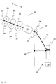
- FIG. 1 shows a schematic view of a section of an air-jet spinning machine according to the invention, which serves to produce roving 1.
- the air-spinning machine can comprise a drafting system 25 with a plurality of corresponding drafting rollers 24, which are supplied with a fiber structure 2, for example in the form of a relined conveyor belt.
- the air spinning machine shown in principle comprises a spaced apart from the drafting 25 yarn-forming unit 33 with an internal and shown in the following figures spinneret 3 and a in FIG. 2 shown Garn Strukturselement 8 in the form of a hollow spindle, wherein the spinneret 3 at least partially limits a vortex chamber 6.
- the fiber structure 2 or at least a part of the fibers of the fiber composite 2 is provided with a protective rotation.
- the air-spinning machine may include a take-off unit 27 with preferably two take-off rollers 26 for the roving 1 (the take-off unit 27 is not absolutely necessary).
- the trigger unit 27 or the yarn-forming unit 33 downstream winding device 31 is present, which in turn should include at least one sleeve drive 30 and one associated with the sleeve drive 30 and in principle known (but not shown) sleeve receptacle, with the aid of which a sleeve 29 can be fixed and set into rotary motion via the sleeve drive 30 in order to be able to wind the roving 1, preferably supported by a traversing unit 28, onto the sleeve 29.
- the air-jet spinning machine works according to a special air-spinning process.
- the fiber structure 2 is guided in a transport direction T via an inlet opening 4 shown in the following figures into the swirl chamber 6 of the spinneret 3 of the yarn-forming unit (wherein the spinneret 3 embodied according to the invention is inserted into the FIGS. 3 to 8 is shown in more detail).
- a protective rotation ie at least part of the fibers of the fiber composite 2 is detected by an air flow, which is generated by appropriately placed spinning air channels 9.
- a part of the fibers is hereby pulled out of the fiber structure 2 at least a little bit and wound around the tip of a yarn formation element 8 projecting into the swirl chamber 6.
- the roving 1 has by the only partial rotation of the fibers a delaying ability, which is essential for the further processing of the roving 1 in a subsequent spinning machine, such as a ring spinning machine.
- a subsequent spinning machine such as a ring spinning machine.
- conventional air-spinning devices impart to the fiber structure 2 such a strong rotation that the necessary distortion following the yarn production is no longer possible. This is also desirable in this case, since conventional air spinning machines are designed to produce a finished yarn, which should usually be characterized by a high strength.
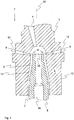
- FIG. 2 shows a spinneret 3 according to known prior art.
- the Garn Strukturselement 8 which also in the case of using the in the FIGS. 3 to 8 spinneret 3 according to the invention would be present, against the transport direction T and through a corresponding opening 7 in the vortex chamber 6.
- all of the spinnerets 3 shown in the figures have a vortex chamber wall 5 which, for example and at least in sections, can have a circular cross-section.
- the vortex chamber wall 5 has an outer side 12 delimiting the spinneret 3 to the outside and an inner side 13 delimiting the vortex chamber 6 (whereby the vortex chamber wall 5 could generally also be designed in several parts).
- spinning air channels 9 are present, via which during the Vorgarnher ein spinning air can be introduced into the vortex chamber 6, the spinning air channels 9 have a spinning air inlet opening 10 and an opening into the vortex chamber 6 spinning air outlet opening 11.
- FIG. 3 shows in principle a section along the line AA in FIG. 4 .
- the Anspinn Kunststoffkanäle 14 preferably comprise at least a first channel portion 17 and a second channel portion 18, the first channel portion 17, starting from the piecing air inlet opening 15 into the second channel section 18, which finally via the Anspinn Kunststoff-outlet opening 16 into the vortex chamber 6 opens.
- Both channel sections 17, 18 in this case enclose an angle ⁇ , the amount of which is preferably in the range lying in the general description.
- the first channel section 17 extends parallel to a central axis 32 of the spinneret 3, as also shown in FIG FIG. 3 is shown.
- the said channel sections 17, 18 can now be prepared by a respective bore, which intersect within the duct wall.
- the Anspinn Kunststoff inlet opening 15 introduced piecing air (based on FIG. 5 ) exits upwardly or outwardly from the Anspinn Kunststoffkanal 14, it is provided, the individual channel sections 17, 18 as in FIG. 6 shown to close.
- appropriate seals 20 may be used, which consist for example of plastic and can be glued into said holes. The result is a Anspinn Kunststoffkanal 14, which allows despite the production by drilling an air deflection within the Wirbelcrowandung 5.
- the Anspinn Kunststoff seen in the transport direction T can be introduced after the piecing air outlet openings 16 via the Anspinn Kunststoff-inlet openings 15 so that the Anspinnluft inlet openings 15 can be placed almost anywhere on the outer side 12 of the spinneret 3.
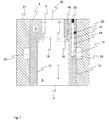
- FIG. 7 One to the Figures 5 and 6 alternative placement of Anspinn Kunststoff-inlet openings 15 shows FIG. 7 , As can be seen from this figure, the Anspinn Kunststoff-inlet openings 15 are not arranged in the region of an end face of the spinneret 3, but in the region of its running between the two end faces outside 12, wherein the Anspinn Kunststoff inlet openings 15 also by (preferably perpendicular to the central axis 32 of the spinneret 3 extending) holes are formed. Further is FIG.
- the spinneret 3 is preferably held in a carrier element 21 of the air-spinning machine, which of course should have holding elements or fastening elements, not shown, in order to be able to fix the spinneret 3 (the illustration in FIG. 7 is therefore only to be understood schematically).
- the carrier element 21 in turn has a Anspinn Kunststoffhunt 23, which may be formed, for example, as the spinneret 3 surrounding annular groove and which is not shown at location with a compressed air supply in combination to bring about the Anspinn Kunststoffäle 14 compressed air into the vortex chamber 6.
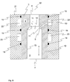
- FIG. 8 shows the execution according to FIG. 7 ,
- the cut was made by the corresponding spinneret 3 not by a Anspinn Kunststoffkanal 14, but a spinning air channel 9.
- the cut was made along a line from the placement of the line BB in FIG. 4 corresponds (even if the execution according to FIG. 4 in some respects from the execution according to FIG. 8 differs).
- FIG. 8 shown and explained in more detail below features also in the spinneret 3 according to FIG. 7 are present, even if these are in FIG. 7 for reasons of clarity are partly not shown.
- the spinneret 3 according to the invention a plurality of spinning air channels 9, over the during the piecing process following normal operation of the air spinning spinning air into the vortex chamber 6 can be introduced to produce a roving 1 from the supplied fiber structure 2.
- the spinning air channels 9 can also be formed by bores, wherein these each, preferably inclined in the transport direction T, from a spinning air inlet opening 10 placed in the region of the outer side 12 of the spinneret 3 to a spinning air outlet opening 11 of the spinneret located in the region of the inner side 13 3 and communicate with a spinning air channel 9 in connection.
- This can also be designed as an annular groove and communicates with a separate source of air pressure.
- a spinneret 3 is obtained in which the spinning air outlet openings 11 and the piecing air outlet openings 16 lie approximately in one plane. Nevertheless, the spinning air and the piecing air can be introduced via separate air chambers (spinning air chamber 22, Anspinn Kunststoffhunt 23), which are seen in the transport direction T spaced from each other.
Landscapes
- Engineering & Computer Science (AREA)
- Mechanical Engineering (AREA)
- Textile Engineering (AREA)
- Spinning Or Twisting Of Yarns (AREA)
Description
Die vorliegende Erfindung betrifft eine Spinndüse für eine Luftspinnmaschine, die der Herstellung von Vorgarn aus einem Faserverband dient, wobei die Spinndüse eine Einlassöffnung für den Eintritt eines Faserverbands aufweist, wobei die Spinndüse eine von einer Wirbelkammerwandung zumindest teilweise begrenzte Wirbelkammer aufweist, die der Einlassöffnung in einer in eingebautem Zustand der Spinndüse vorgegebenen Transportrichtung des Faserverbands nachgeordnet ist, wobei die Spinndüse eine von der Einlassöffnung in der Transportrichtung beabstandete Öffnung aufweist, über die eine Hohlspindel in die Wirbelkammer einführbar ist, wobei die Spinndüse zumindest einen Spinnluftkanal aufweist, über den Luft ins Innere der Wirbelkammer einbringbar ist, wobei sich der Spinnluftkanal zwischen einer Spinnluft-Eintrittsöffnung und einer Spinnluft-Austrittsöffnung erstreckt und die Spinnluft-Eintrittsöffnung im Bereich einer Außenseite der Spinndüse und die Spinnluft-Austrittsöffnung im Bereich einer die Wirbelkammer begrenzenden Innenseite der Wirbelkammerwandung angeordnet ist, wobei die Spinndüse zumindest einen Anspinnluftkanal aufweist, über den ebenfalls Luft ins Innere der Wirbelkammer einbringbar ist, wobei sich der Anspinnluftkanal zwischen einer Anspinnluft-Eintrittsöffnung und einer Anspinnluft-Austrittsöffnung erstreckt und die Anspinnluft-Eintrittsöffnung im Bereich der genannten Außenseite der Spinndüse und die Anspinnluft-Austrittsöffnung im Bereich der genannten Innenseite der Wirbelkammerwandung angeordnet ist, und wobei die Spinnluft-Eintrittsöffnung und die Anspinnluft-Eintrittsöffnung in der genannten Transportrichtung voneinander beabstandet sind.The present invention relates to a spinneret for an air spinning machine, which serves for the production of roving from a fiber structure, wherein the spinneret has an inlet opening for the entry of a fiber composite, wherein the spinneret has a vortex chamber of an at least partially limited vortex chamber, the inlet opening in a arranged in the installed state of the spinneret predetermined transport direction of the fiber assembly, wherein the spinneret has a spaced from the inlet opening in the transport direction opening through which a hollow spindle is inserted into the vortex chamber, wherein the spinneret has at least one spin air duct, via the air into the interior Whirl chamber can be introduced, wherein the spinning air duct extends between a spinning air inlet opening and a spinning air outlet opening and the spinning air inlet opening in the region of an outer side of the spinneret and the spinning air outlet The spinneret has at least one Anspinnluftkanal via which also air into the interior of the vortex chamber can be introduced, wherein the Anspinnluftkanal extends between a Anspinnluft inlet opening and a Anspinnluft outlet opening and the piecing air Inlet opening in the region of said outside of the spinneret and the Anspinnluft outlet opening in the region of said inner side of the Wirbelkammerwandung is arranged, and wherein the spinning air inlet opening and the Anspinnluft inlet opening are spaced apart in said transport direction.
Darüber hinaus wird eine Luftspinnmaschine zur Herstellung von Vorgarn aus einem Faserverband beschrieben, wobei die Luftspinnmaschine zumindest eine Spinnstelle mit einer Spinndüse umfasst, und wobei die Spinnstelle ausgebildet ist, einem der Spinndüse in einer Transportrichtung zugeführten Faserverband innerhalb einer durch die Spinndüse teilweise begrenzten Wirbelkammer mit Hilfe einer Luftströmung eine Drehung zu erteilen.In addition, an air spinning machine for producing roving from a fiber structure is described, wherein the air spinning machine comprises at least one spinning station with a spinneret, and wherein the spinning station is formed, one of the spinneret in a transport direction supplied fiber strand within a partially limited by the spinneret vortex chamber with the help to give a rotation to an air flow.
Vorgarn wird mit Hilfe von Vorspinnmaschinen aus meist mit Hilfe von Strecken vorbehandelten (z. B. dublierten) Faserbändern hergestellt und dient als Vorlage für den anschließenden Spinnprozess, bei dem die einzelnen Fasern des Vorgarns, beispielsweise mit Hilfe einer Ringspinnmaschine, zu einem Fasergarn versponnen werden. Um dem Vorgarn eine gewisse Festigkeit zu verleihen, hat es sich bewährt, den vorgelegten Faserverband während der Herstellung des Vorgarns mit Hilfe eines Streckwerks, das meist Teil der Vorspinnmaschine ist, zu verstrecken und anschließend mit einer Schutzdrehung zu versehen. Die genannte Festigkeit ist wichtig, um ein Reißen des Vorgarns beim Aufwickeln auf eine Spule bzw. während der Zufuhr zur nachgeschalteten Spinnmaschine zu verhindern. Die erteilte Schutzdrehung darf jedoch nur so stark sein, dass ein Zusammenhalt der einzelnen Fasern während der einzelnen Auf- bzw. Abspulvorgänge sowie entsprechender Transportvorgänge zwischen den jeweiligen Maschinentypen gewährleistet ist. Hingegen muss auch trotz der Schutzdrehung sichergestellt werden, dass das Vorgarn in einer Spinnmaschine weiterverarbeitet werden kann - das Vorgarn muss also weiterhin verzugsfähig sein.Roving is produced with the aid of roving machines, usually with the aid of stretch-pretreated (eg doubled) slivers, and serves as a template for the subsequent spinning process in which the individual fibers of the roving are spun into a fiber yarn, for example by means of a ring spinning machine , In order to give the roving a certain strength, it has been proven to stretch the submitted fiber structure during the production of the roving using a drafting system, which is usually part of the roving, and then to provide a protective rotation. Said strength is important to prevent ripping of the roving during winding on a spool or during the supply to the downstream spinning machine. However, the protective rotation granted may only be so strong that a cohesion of the individual fibers is ensured during the individual winding and unwinding operations as well as corresponding transport processes between the respective machine types. On the other hand, despite the protective rotation, it must be ensured that the roving can be further processed in a spinning machine - the roving must therefore continue to be delayable.
Um ein entsprechendes Vorgarn herzustellen, kommen vorrangig so genannte Flyer zum Einsatz, deren Liefergeschwindigkeit jedoch aufgrund auftretender Fliehkräfte beschränkt ist. Es gab daher bereits vielfältige Vorschläge, den Flyer zu umgehen oder durch einen alternativen Maschinentypus zu ersetzen (siehe beispielsweise
Unter anderem wurde in diesem Zusammenhang auch bereits vorgeschlagen, Vorgarn mit Hilfe von Luftspinnmaschinen herzustellen, bei dem die Schutzdrehung mit Hilfe von Luftströmungen erzeugt wird. Das Grundprinzip besteht hierbei darin, einen Faserverband durch eine Wirbelkammer zu führen, in der mit Hilfe von Spinnluftdüsen ein Luftwirbel erzeugt wird. Dieser bewirkt schließlich, dass ein Teil der äußeren Fasern als so genannte Umwindefasern um den zentral verlaufenden Faserstrang geschlungen wird, der wiederum aus im Wesentlichen parallel zueinander verlaufenden Kernfasern besteht.Among other things, it has already been proposed in this context to produce roving by means of air spinning machines, in which the protective rotation is generated by means of air currents. The basic principle here is to guide a fiber structure through a vortex chamber in which an air vortex is generated by means of spinning air nozzles. This finally causes a part of the outer fibers to be wound around the centrally extending fiber strand as so-called binding fibers, which in turn consists essentially of mutually parallel core fibers.
Wie auch beim Spinnen von Garn ist es jedoch auch bei der Herstellung von Vorgarn regelmäßig notwendig, den der Vorspinnmaschine zugeführten Faserverband anzuspinnen, bevor der eigentliche Spinnvorgang gestartet werden kann. Ein entsprechendes Anspinnen kann beispielsweise beim Anschalten der Spinnmaschine oder nach einem Riss des Vorgarns oder des Faserverbands erforderlich sein, wobei der Faserverband in diesem Fall in die Wirbelkammer eingeführt und dort einer Wirbelluftströmung ausgesetzt wird, um den eingeführten Anfangsabschnitt des Faserverbands in eine Drehung zu versetzen und hierdurch die eigentliche Vorgarnherstellung in Gang zu setzen. Die Wirbelluftströmung sollte in diesem Anfangsstadium jedoch meist eine andere Charakteristik aufweisen als während des regulären Spinnbetriebs, bei dem die Wirbelkammer bereits von einem durchgängigen Faserstrang passiert wird (der Faserstrang setzt sich hierbei aus dem Faserverband im Bereich der Einlassöffnung der Spinndüse und dem innerhalb der Wirbelkammer aus dem Faserverband hergestellten und die Wirbelkammer über einen Abzugskanal verlassenden Vorgarn zusammen).However, as with the spinning of yarn, it is also regularly necessary in the production of roving to spin the fiber strand supplied to the roving frame before the actual spinning process can be started. An appropriate piecing may be required, for example, when turning on the spinning machine or after a rip of the roving or fiber dressing, in which case the fiber strand is introduced into the swirling chamber where it is subjected to fluidized air flow to rotate the inserted initial section of the fiber strand and thereby starting the actual production of roving. However, the vortex air flow at this initial stage usually has a different characteristic than during regular spinning operation in which the vortex chamber is already passed by a continuous fiber strand (the fiber strand is made up of the fiber structure in the region of the inlet opening of the spinneret and within the vortex chamber the roving produced by the fiber structure and the vortex chamber leaving a vortex channel together).
Es hat sich daher bewährt, neben den Spinnluftdüsen, die während des dem Anspinnvorgang folgenden Spinnbetriebs zum Einsatz kommen, zusätzliche Anspinnluftdüsen vorzusehen, die ebenfalls tangential in die Wirbelkammer münden, jedoch eine gegenüber den Anspinndüsen veränderte Ausrichtung haben. Während des Anspinnvorgangs werden in der Regel nur (oder zusätzlich zu den Spinnluftdüsen) die Anspinnluftdüsen mit Druckluft beaufschlagt, resultierend in einer für den Beginn der Vorgarnherstellung optimierten Luftführung innerhalb der Wirbelkammer.It has therefore proven useful, in addition to the spinning air nozzles, which are used during the piecing process following spinning operation to provide additional Anspinnluftdüsen that also open tangentially into the swirl chamber, but have a relation to the Anspinndüsen changed orientation. During piecing, usually only (or in addition to the spinning air nozzles) the Anspinnluftdüsen be pressurized with compressed air, resulting in an optimized for the start of Vorgarnherstellung air flow within the vortex chamber.
Da jedoch die Spinnluftdüsen und die Anspinnluftdüsen separat mit Druckluft beaufschlagt werden können müssen, sind für die oben genannten Luftdüsenarten auch separate Luftversorgungen nötig, die alle in dem beschränkten Bauraum der Spinndüse untergebracht werden müssen.However, since the spinning air nozzles and Anspinnluftdüsen must be able to be acted upon separately with compressed air, separate air supplies are required for the above types of air nozzles, all of which must be accommodated in the limited space of the spinneret.
Aufgabe der vorliegenden Erfindung ist es, eine Spinndüse sowie eine damit ausgerüstete Luftspinnmaschine zur Herstellung von Vorgarn vorzuschlagen, bei der die einzelnen Strömungsabschnitte für die Spinn- und Anspinnluft möglichst vorteilhaft platziert und ausgerichtet sind.The object of the present invention is to propose a spinneret and an air-spinning machine equipped therewith for the production of roving in which the individual flow sections for the spinning and piecing air are advantageously positioned and aligned.
Die Aufgabe wird gelöst durch eine Spinndüse und eine Luftspinnmaschine mit den Merkmalen der unabhängigen Patentansprüche.The object is achieved by a spinneret and an air-jet spinning machine having the features of the independent patent claims.
Erfindungsgemäß zeichnet sich die Spinndüse nun dadurch aus, dass sich der wenigstens eine Anspinnluftkanal ausgehend von seiner Anspinnluft-Eintrittsöffnung zumindest teilweise entgegen die Transportrichtung erstreckt, wobei es sich bei der Spinndüse um den Teil einer entsprechenden Luftspinnmaschine handelt, der die Wirbelkammer umgibt bzw. bildet und die Spinnluftdüsen und die Anspinnluftdüsen zumindest teilweise umfasst (wobei die Spinndüse selbst ein- oder mehrteilig ausgebildet sein kann). Während es bei bekannten Spinndüsen stets vorgesehen ist, die Anspinnluft ausschließlich in Transportrichtung zu führen, hat die erfindungsgemäße Lösung den Vorteil, dass die Anspinnluft-Eintrittsöffnungen (über die die Anspinnluft in den Anspinnluftkanal eintritt) in Transportrichtung gesehen nach den Spinnluft-Eintrittsöffnungen (über die die Spinnluft in den Spinnluftkanal eintritt) platziert werden können.According to the invention, the spinneret is characterized in that the at least one piecing air channel extends at least partially opposite to the transport direction, starting from its piecing air inlet opening, wherein the spinneret is the part of a corresponding air spinning machine which surrounds or forms the vortex chamber and the spinning air nozzles and Anspinnluftdüsen at least partially comprises (wherein the spinneret itself may be formed one or more parts). While it is always provided in known spinnerets to lead the Anspinnluft exclusively in the transport direction, the solution according to the invention has the advantage that the Anspinnluft inlet openings (over which the Anspinnluft enters the Anspinnluftkanal) seen in the transport direction after the spinning air inlet openings (on the the spinning air enters the spin air duct) can be placed.
Die Anspinnluft-Austrittsöffnungen (über die die Anspinnluft in die Wirbelkammer eintritt) können somit in Transportrichtung gesehen in etwa auf Höhe der Spinnluft-Austrittsöffnungen platziert sein, wobei dennoch beide Luftkanäle (Spinnluftkanal und Anspinnluftkanal) von unterschiedlichen Druckluftquellen versorgt werden können.The Anspinnluft outlet openings (over which the Anspinnluft enters the vortex chamber) can thus be placed in the transport direction approximately at the height of the spinning air outlet openings, yet both air channels (spinning air duct and Anspinnluftkanal) can be supplied by different sources of compressed air.
Generell sei an dieser Stelle darauf hingewiesen, dass in der folgenden Beschreibung meist nur ein Spinnluftkanal und ein Anspinnluftkanal beschrieben sind. Selbstverständlich ist es von Vorteil, wenn die Spinndüse mehrere Spinnluftkanäle und mehrere Anspinnluftkanäle (mit den jeweils zugehörigen Eintritts- und Austrittsöffnungen besitzt), wobei die jeweiligen Austrittsöffnungen tangential in die Wirbelkammer münden sollten. Die mit Bezug auf den jeweils einen Spinnluftkanal bzw. den jeweils einen Anspinnluftkanal beschriebenen Merkmale sind daher auf die restlichen Spinnluft- bzw. Anspinnluftkanäle der entsprechenden Spinndüse übertragbar.Generally, it should be noted at this point that in the following description usually only a spinning air duct and a Anspinnluftkanal are described. Of course, it is advantageous if the spinneret several Spinnluftkanäle and Anspinnluftkanäle several (with the respective associated inlet and outlet openings has), wherein the respective outlet openings should open tangentially into the vortex chamber. The features described with respect to the respective one spinning air channel or the one piecing air channel are therefore transferable to the remaining spinning air or piecing air channels of the corresponding spinneret.
Im Rahmen der Erfindung ist es äußert vorteilhaft, wenn der Anspinnluftkanal einen ersten Kanalabschnitt umfasst, der sich ausgehend von der Anspinnluft-Eintrittsöffnung innerhalb der Wirbelkammerwandung zumindest teilweise entgegen die Transportrichtung erstreckt, wobei der Anspinnluftkanal darüber hinaus einen zweiten Kanalabschnitt umfasst, der sich ausgehend vom ersten Kanalabschnitt in Richtung der Anspinnluft-Austrittsöffnung erstreckt. Die Anspinnluftführung erfolgt in diesem Fall nicht durchgehend geradlinig. Vielmehr ändert sich der Verlauf des Anspinnluftkanals (der sich generell zwischen der im Bereich der Außenseite platzierten Anspinnluft-Eintrittsöffnung und der in die Wirbelkammer mündenden Anspinnluft-Austrittsöffnung erstreckt) innerhalb der Wirbelkammerwandung wenigstens einmal. Beispielsweise ist es denkbar, dass der erste Kanalabschnitt ausgehend von der Anspinnluft-Eintrittsöffnung entgegen der Transportrichtung und parallel zu einer Mittelachse der Spinndüse verläuft. Innerhalb der Wirbelkammerwandung geht er schließlich, beispielsweise über einen Knick, in den zweiten Kanalabschnitt über, der sich wiederum in Richtung der Wirbelkammer erstreckt.In the context of the invention, it is extremely advantageous if the Anspinnluftkanal comprises a first channel section, which extends from the Anspinnluft inlet opening within the Wirbelkammerwandung at least partially opposite to the transport direction, wherein the Anspinnluftkanal beyond a second channel section includes, extending from the first channel portion in the direction of Anspinnluft-outlet opening. The Anspinnluftführung in this case is not continuous straight. Rather, the course of Anspinnluftkanals (which generally extends between the Anspinnluft inlet opening placed in the region of the outside and the Anspinnluft-outlet opening into the swirl chamber) within the Wirbelkammerwandung changes at least once. For example, it is conceivable that the first channel section, starting from the piecing air inlet opening, runs counter to the transport direction and parallel to a central axis of the spinneret. Within the vortex chamber wall, he finally goes over, for example via a kink, in the second channel section, which in turn extends in the direction of the vortex chamber.
Besondere Vorteile bringt es mit sich, wenn der erste Kanalabschnitt (in einer Seitenansicht der Spinndüse) mit einer Mittelachse der Spinndüse einen Winkel einschließt, dessen Betrag 0° bis 30°, bevorzugt 0° bis 15°, besonders bevorzugt 0° bis 10°, beträgt. Während ein Winkel von 0° bedeutet, dass der erste Kanalabschnitt parallel zur genannten Mittelachse der Spinndüse verläuft, hat ein Winkel von über 0° zur Folge, dass der erste Kanalabschnitt bezogen auf die Mittelachse schräg verläuft.Particular advantages arise when the first channel section (in a side view of the spinneret) encloses an angle with a central axis of the spinneret whose magnitude is 0 ° to 30 °, preferably 0 ° to 15 °, particularly preferably 0 ° to 10 °, is. While an angle of 0 ° means that the first channel section is parallel to the central axis of the spinneret, an angle greater than 0 ° results in the first channel section being inclined with respect to the central axis.
Des Weiteren ist es vorteilhaft, wenn der erste Kanalabschnitt und/oder der zweite Kanalabschnitt eine geradlinig verlaufende Mittelachse aufweisen. In diesem Fall kann der jeweilige Kanalabschnitt durch eine entsprechende Bohrung hergestellt werden, die in die Wirbelkammerwandung eingebracht wird. Zudem werden Beeinträchtigungen der jeweiligen Luftströmungen vermieden. Die Durchmesser der jeweiligen Kanalabschnitte sind vorzugsweise gleich groß oder weichen um nur maximal 20 % voneinander ab.Furthermore, it is advantageous if the first channel section and / or the second channel section have a rectilinear central axis. In this case, the respective channel section can be made through a corresponding bore which is introduced into the vortex chamber wall. In addition, impairments of the respective air currents are avoided. The diameters of the respective channel sections are preferably the same size or deviate from each other by only a maximum of 20%.
Vorteilhaft ist es zudem, wenn der erste Kanalabschnitt und/oder der zweite Kanalabschnitt durch eine von der Außenseite der Spinndüse in die Spinndüse eingebrachte Bohrung gebildet ist. Eine derartige Bohrung kann einfach und vor allem, mit Bezug auf seine Ausrichtung, äußerst genau eingebracht werden.It is also advantageous if the first channel section and / or the second channel section is formed by a bore introduced from the outside of the spinneret into the spinneret. Such a bore can be easily and especially, with respect to its orientation, very precisely introduced.
In diesem Zusammenhang ist es von besonderem Vorteil, wenn der erste Kanalabschnitt und der zweite Kanalabschnitt durch eine von der Außenseite der Spinndüse in die Spinndüse eingebrachte Bohrung gebildet ist, wobei sich die jeweiligen Bohrungen innerhalb der Wirbelkammerwandung schneiden. Der Schnittpunkt beider Bohrungen stellt in diesem Fall den Übergang vom ersten in den zweiten Kanalabschnitt dar.In this context, it is particularly advantageous if the first channel section and the second channel section through a from the outside of the spinneret in the spinneret introduced bore is formed, wherein the respective holes intersect within the Wirbelkammerwandung. The intersection of both holes represents in this case the transition from the first to the second channel section.
Vorteilhaft ist es, wenn die genannten Bohrungen zumindest einseitig im Bereich der Außenseite der Spinndüse durch eine luftdichte Abdichtung verschlossen sind. In diesem Fall kann der Anspinnluftkanal durch mehrere Bohrungen gebildet werden, die sich jeweils von der Außenseite in die Wirbelkammer erstrecken, wobei zumindest eine der Bohrungen die Wirbelkammerwandung ausgehend von der Außenseite der Spinndüse vollständig durchdringen kann. Durch die entsprechende Abdichtung einzelner Bohrungsabschnitte im Bereich der Außenseite der Spinndüse kann schließlich ein Kanalsystem, bestehend aus erstem und zweitem Kanalabschnitt, erzeugt werden, das sich innerhalb der Wirbelkammerwandung erstreckt, ausschließlich durch Bohrungen erstellt wurde und dennoch eine abgeknickte Druckluftführung ermöglicht. Vorzugsweise wird der erste Kanalabschnitt hierbei durch eine von einer Stirnseite der Spinndüse ausgehende und sich in Transportrichtung erstreckend erste Bohrung gebildet, wobei die Bohrung nachträglich im Bereich der Stirnseite mit Hilfe einer Abdichtung (die vorzugsweise eingeklebt ist) abgedichtet ist. Der zweite Kanalabschnitt wird in diesem Fall vorzgusweise durch eine zweite Bohrung gebildet, die sich ausgehend von einer zwischen den beiden Stirnseiten der Spinndüse erstreckenden Außenseite bis in die Wirbelkammer erstreckt, wobei sich beide Bohrungen innerhalb der Wirbelkammerwandung schneiden und die zweite Bohrung im Bereich der Außenseite abgedichtet ist. Wird nun die erste Bohrung in Transportrichtung gesehen hinter der zweiten Bohrung von der Außenseite her angebohrt, so entsteht die notwendige Anspinnluft-Eintrittsöffnung, so kann die Anspinndruckluft schließlich über die Anspinnluft-Eintrittsöffnung und die daran anschließende erste Bohrung bis in den Bereich der zweiten Bohrung und von dort in die Wirbelkammer strömen.It is advantageous if the said holes are closed at least on one side in the region of the outside of the spinneret by an airtight seal. In this case, the Anspinnluftkanal can be formed by a plurality of bores, each extending from the outside into the vortex chamber, wherein at least one of the holes can completely penetrate the Wirbelkammerwandung, starting from the outside of the spinneret. By the corresponding sealing of individual bore sections in the region of the outside of the spinneret, finally, a channel system consisting of first and second channel section can be produced, which extends within the vortex chamber wall, was created exclusively by drilling and still allows a bent compressed air guide. Preferably, the first channel section is in this case formed by a first bore extending from an end face of the spinneret and extending in the transport direction, wherein the bore is subsequently sealed in the region of the end face by means of a seal (which is preferably glued in). The second channel portion is in this case vorzgusweise formed by a second bore which extends from an extending between the two end faces of the spinneret outside to the vortex chamber, both holes intersect within the Wirbelkammerwandung and sealed the second bore in the outer side is. If now the first hole drilled in the transport direction behind the second hole drilled from the outside, the result is the necessary Anspinnluft inlet opening, so the Anspinndruckluft finally on the Anspinnluft inlet opening and the adjoining first bore into the region of the second bore and from there, pour into the vortex chamber.
Besonders vorteilhaft ist es somit, wenn der zweite Kanalabschnitt zwischen einer Abdichtung des ersten Kanalabschnitts und der Anspinnluft-Eintrittsöffnung vom ersten Kanalabschnitt abzweigt. Die beiden Kanalabschnitte schneiden sich in diesem Fall innerhalb der Wirbelkammerwandung, wobei der erste Kanalabschnitt einerseits über seine Anspinnluft-Eintrittsöffnung versorgt werden kann und auf der anderen Seite durch eine Abdichtung luftdicht verschlossen ist. Der zweite Kanalabschnitt erstreckt sich in diesem Fall von der Anspinnluft-Austrittsöffnung bis in den ersten Kanalabschnitt. Der weitere Verlauf der den zweiten Kanalabschnitt bildenden Bohrung ist schließlich zwischen dem ersten Kanalabschnitt und der Außenseite der Spinndüse mit Hilfe der genannten Abdichtung verschlossen, so dass innerhalb der Wirbelkammerwandung eine Zwangsführung für die Anspinnluft derart vorhanden ist, dass diese ausschließlich von der Anspinnluft-Eintrittsöffnung über den ersten Kanalabschnitt und von dort über den zweiten Kanalabschnitt und über die Anspinnluft-Austrittsöffnung in die Wirbelkammer strömen kann.It is thus particularly advantageous if the second channel section branches off from the first channel section between a seal of the first channel section and the piecing air inlet opening. The two channel sections intersect in this case within the Wirbelkammerwandung, wherein the first channel section on the one hand via its Anspinnluft inlet opening can be supplied and is hermetically sealed on the other side by a seal. In this case, the second channel section extends from the piecing air outlet opening into the first channel section. The further course of the second channel section forming hole is finally closed between the first channel section and the outside of the spinneret with the aid of said seal, so that within the Wirbelkammerwandung a forced operation for the piecing air is present such that this exclusively from the Anspinnluft inlet opening the first channel portion and from there via the second channel portion and the Anspinnluft-outlet opening can flow into the vortex chamber.
Vorteile bringt es zudem mit sich, wenn der zweite Kanalabschnitt in einem Winkel α von dem ersten Kanalabschnitt abzweigt, wobei der Betrag des genannten Winkels 40° bis 80°, bevorzugt 45° bis 75°, besonders bevorzugt 50° bis 70°, beträgt. Ein derartiger Winkel bewirkt eine Luftströmung, die vor dem Eintritt in die Wirbelkammer nicht nochmals umgelenkt werden muss und somit ohne weitere Eingriffe einen erfolgreichen Anspinnvorgang verspricht.It also brings advantages when the second channel section branches off at an angle α from the first channel section, wherein the amount of said angle is 40 ° to 80 °, preferably 45 ° to 75 °, particularly preferably 50 ° to 70 °. Such an angle causes an air flow, which does not have to be redirected again before entering the vortex chamber and thus promises a successful piecing without further intervention.
Besondere Vorteile bringt es mit sich, wenn die Anspinnluft-Eintrittsöffnung in Transportrichtung gesehen nach der Spinnluft-Austrittsöffnung und/oder nach der Anspinnluft-Austrittsöffnung angeordnet ist. Vorteile bringt es zudem mit sich, wenn die Anspinnluft-Eintrittsöffnung in Transportrichtung gesehen nach der Spinnluft-Eintrittsöffnung angeordnet ist. Entgegen der Transportrichtung ist somit die Anspinnluft-Eintrittsöffnung an erster Stelle platziert, wobei sich die Spinnlufteintrittsöffnung in etwa auf Höhe der Spinnluft-Austrittsöffnung und/oder der Anspinnluft-Austrittsöffnung befinden kann.It has particular advantages when the Anspinnluft inlet opening is arranged in the transport direction after the spinning air outlet opening and / or after the piecing air outlet opening. It also brings advantages when the Anspinnluft inlet opening is arranged in the transport direction after the spinning air inlet opening. Contrary to the transport direction, the Anspinnluft inlet opening is thus placed in the first place, wherein the spinning air inlet opening can be located approximately at the height of the spinning air outlet opening and / or the Anspinnluft outlet opening.
Des Weiteren ist es vorteilhaft, wenn die Spinnluft-Austrittsöffnung und die Anspinnluft-Austrittsöffnung in einer gemeinsamen und senkrecht zur Transportrichtung verlaufenden Ebene angeordnet sind oder in Transportrichtung gesehen weniger als 3 mm, bevorzugt weniger als 2 mm, besonders bevorzugt weniger als 1 mm, voneinander beabstandet sind. Dennoch können der Spinnluftkanal und der Anspinnluftkanal von separaten Druckluftversorgungen versorgt werden, da die Spinnluft-Eintrittsöffnung und die Anspinnlufteintrittsöffnung in Transportrichtung gesehen voneinander beabstandet sind.Furthermore, it is advantageous if the spinning-air outlet opening and the piecing-air outlet opening are arranged in a common plane extending perpendicular to the transport direction or less than 3 mm, preferably less than 2 mm, particularly preferably less than 1 mm, viewed from one another in the transport direction are spaced. Nevertheless, the spin air duct and Anspinnluftkanal of separate Compressed air supplies are supplied, since the spinning air inlet opening and Anspinnlufteintrittsöffnung seen in the transport direction are spaced from each other.
Besondere Vorteile bringt es mit sich, wenn die Anspinnluft-Eintrittsöffnung und die Anspinnluft-Austrittsöffnung in Transportrichtung gesehen wenigstens 4 mm, bevorzugt wenigstens 8 mm, besonders bevorzugt wenigstens 12 mm, und/oder weniger als 30 mm, bevorzugt weniger als 25 mm, besonders bevorzugt weniger als 20 mm, voneinander beabstandet sind. Die genannten Bereiche stellen sicher, dass zwischen den jeweiligen Eintrittsöffnungen ausreichend Bauraum vorhanden ist, um diese über separate Druckluftversorgungen mit Druckluft versorgen zu können, ohne dass die Spinndüse hierbei derart große Abmessungen annehmen muss, die sie für den Einbau in eine Luftpinnmaschine ungeeignet machen würden.It has particular advantages when the piecing air inlet opening and the piecing air outlet opening seen in the transport direction at least 4 mm, preferably at least 8 mm, more preferably at least 12 mm, and / or less than 30 mm, preferably less than 25 mm, especially preferably less than 20 mm, are spaced from each other. The said areas ensure that sufficient space is available between the respective inlet openings in order to be able to supply them with compressed air via separate compressed-air supplies without the spinneret having to assume such large dimensions here that it would be unsuitable for installation in an air-spinning machine.
Die erfindungsgemäße Luftspinnmaschine zur Herstellung von Vorgarn zeichnet sich schließlich dadurch aus, dass sie zumindest eine Spinnstelle mit einer Spinndüse umfasst, wobei die Spinnstelle ausgebildet ist, einem der Spinndüse in einer Transportrichtung zugeführten Faserverband innerhalb einer durch die Spinndüse teilweise begrenzten Wirbelkammer mit Hilfe einer Luftströmung eine Drehung zu erteilen, und wobei die Spinndüse die erfindungsgemäßen Merkmale der bisherigen bzw. nachfolgenden Beschreibung aufweist. Die Merkmale können hierbei einzeln oder in beliebiger Kombination verwirklicht sein, solange es hierbei nicht zu Widersprüchen kommt.The air-jet spinning machine according to the invention for the production of roving is finally distinguished by the fact that it comprises at least one spinning station with a spinneret, wherein the spinning station is formed, one of the spinneret in a transport direction supplied fiber strand within a partially limited by the spinneret vortex chamber by means of an air flow Rotation, and wherein the spinneret has the features according to the invention the previous or subsequent description. The features can be realized individually or in any combination, as long as it does not lead to contradictions.
In diesem Zusammenhang ist es von Vorteil, wenn die Spinndüse mehrere Spinnluftkanäle und mehrere davon in Transportrichtung beabstandete Anspinnluftkanäle aufweist, wobei die Spinnluft-Eintrittsöffnungen der Spinnluftkanäle und die Anspinnluft-Eintrittsöffnungen der Anspinnluftkanäle durch Dichtelemente, vorzugweise in Form von Dichtringen, voneinander getrennt sind. Die Spinnluft-Eintrittsöffnungen und die Anspinnluft-Eintrittsöffnungen sind bevorzugt im Bereich der Außenseite der Spinndüse, insbesondere auf einem zwischen den Stirnseiten der Spinndüse verlaufenden Oberflächenabschnitt derselben, angeordnet. Folglich münden auch die entsprechenden Druckluftquellen für die Spinn- und die Anspinnluft im Bereich der Außenseite der Spinndüse in die jeweiligen Luftkanäle. Durch die Dichtelemente wird schließlich sichergestellt, dass zwischen den Spinnluftkanälen und den Anspinnluftkanälen im Bereich der Außenseite der Spinndüse kein Luftaustausch möglich ist. Beide Luftkanalarten können somit unabhängig, vorzugsweise abwechselnd, mit Druckluft beaufschlagt werden, ohne dass es zu ungewollten Leckluftströmungen kommen würde.In this context, it is advantageous if the spinneret has a plurality of spinning air ducts and a plurality of Anspinnluftkanäle spaced apart in the transport direction, wherein the spinning air inlet openings of the spinning air ducts and Anspinnluft inlet openings of Anspinnluftkanäle by sealing elements, preferably in the form of sealing rings, are separated. The spinning-air inlet openings and the piecing-air inlet openings are preferably arranged in the region of the outside of the spinneret, in particular on a surface section of the same between the end faces of the spinneret. Consequently, the corresponding compressed-air sources for the spinning and piecing air in the region of the outside of the spinneret also open into the respective air channels. By the sealing elements is finally ensured that between the spinning air ducts and Anspinnluftkanälen in the region of the outside of the spinneret no air exchange is possible. Both types of air ducts can thus be acted upon independently, preferably alternately, with compressed air, without there being any unwanted leakage air flows.
Auch ist es äußert vorteilhaft, wenn die Dichtelemente im Bereich einer Außenseite der Spinndüse platziert sind und diese vorzugsweise umfangsmäßig umschließen. Vorzugsweise sind die Dichtelemente als ringförmige Dichtgummis ausgebildet, wobei es insbesondere von Vorteil ist, wenn jeweils ein Dichtelement (in Transportrichtung gesehen) zwischen der Einlassöffnung der Spinndüse und den Spinnluft-Eintrittsöffnungen, zwischen den Spinnlufteintrittsöffnungen und den Anspinnluft-Eintrittsöffnungen und zwischen den Anspinnluft-Eintrittsöffnungen und der Öffnung des Spinndüse, über die das Vorgarn die Spinndüse verlässt, angeordnet sind.It is also extremely advantageous if the sealing elements are placed in the region of an outer side of the spinneret and preferably enclose them circumferentially. Preferably, the sealing elements are designed as annular sealing rubbers, wherein it is particularly advantageous if in each case a sealing element (seen in the transport direction) between the inlet opening of the spinneret and the spinning air inlet openings, between the spinning air inlet openings and the piecing air inlet openings and between the piecing air inlet openings and the opening of the spinneret over which the roving leaves the spinneret are arranged.
Schließlich ist es vorteilhaft, wenn die Spinnstelle ein die Spinndüse aufnehmendes Trägerelement aufweist, wobei das Trägerelement eine den Spinnluft-Eintrittsöffnungen benachbarte und mit diesen in Fluidverbindung stehende Spinnluftkammer aufweist, und wobei das Trägerelement eine den Anspinnluft-Eintrittsöffnungen benachbarte und mit diesen in Fluidverbindung stehende Anspinnluftkammer aufweist. Das Trägerelement kann beispielsweise eine Bohrung aufweisen, in die die Spinndüse gesteckt ist (die Befestigung der Spinndüse in dem Träger kann beispielsweise mittels Schrauben verwirklicht sein). Ferner ist es von Vorteil, wenn die Luftkammer und die Anspinnluftkammer mit Hilfe der im vorherigen Abschnitt genannten Dichtelemente luftdicht voneinander getrennt sind.Finally, it is advantageous if the spinning station has a spinneret-receiving carrier element, wherein the carrier element has a spinning air inlet openings adjacent and in fluid communication therewith spinning air chamber, and wherein the carrier element adjacent to Anspinnluft inlet openings and in fluid communication Anspinnluftkammer having. The carrier element may, for example, have a bore into which the spinneret is inserted (the attachment of the spinneret in the carrier may, for example, be realized by means of screws). Furthermore, it is advantageous if the air chamber and the piecing air chamber are airtight separated from each other by means of the sealing elements mentioned in the previous section.
Weitere Vorteile der Erfindung sind in den nachfolgenden Ausführungsbeispielen beschrieben. Es zeigen:
-
Figur 1 - eine Seitenansicht einer Luftspinnmaschine,
-
Figur 2 - eine Schnittdarstellung einer bekannten Spinndüse,
-
Figur 3 - eine Schnittdarstellung einer erfindungsgemäßen Spinndüse,
-
Figur 4 - eine Ansicht einer erfindungsgemäßen Spinndüse mit Blick gegen die Transportrichtung,
-
Figur 5 - eine Schnittdarstellung einer weiteren erfindungsgemäßen Spinndüse,
-
Figur 6 - die
Ansicht gemäß Figur 5 mit abgedichtetem Anspinnluftkanal, -
Figur 7 - eine Schnittdarstellung der Spinndüse gemäß
Figur 6 , wobei die Spinndüse in einem Trägerelement der Luftspinnmaschine gehalten ist, und -
Figur 8 - eine weitere Schnittdarstellung der Anordnung gemäß
Figur 7
- FIG. 1
- a side view of an air-spinning machine,
- FIG. 2
- a sectional view of a known spinneret,
- FIG. 3
- a sectional view of a spinneret according to the invention,
- FIG. 4
- a view of a spinneret according to the invention with a view towards the transport direction,
- FIG. 5
- a sectional view of another spinneret according to the invention,
- FIG. 6
- the view according to
FIG. 5 with sealed Anspinnluftkanal, - FIG. 7
- a sectional view of the spinneret according to
FIG. 6 wherein the spinneret is held in a carrier element of the air-spinning machine, and - FIG. 8
- a further sectional view of the arrangement according to
FIG. 7 ,
Ebenso kann die Luftspinnmaschine eine Abzugseinheit 27 mit vorzugsweise zwei Abzugswalzen 26 für das Vorgarn 1 umfassen (die Abzugseinheit 27 ist nicht zwingend notwendig). Des Weiteren ist in der Regel eine der Abzugseinheit 27 bzw. der garnbildenden Einheit 33 nachgeschaltete Spulvorrichtung 31 vorhanden, die wiederum wenigstens einen Hülsenantrieb 30 sowie jeweils eine mit dem Hülsenantrieb 30 in Verbindung stehende und prinzipiell bekannte (jedoch nicht gezeigte) Hülsenaufnahme umfassen sollte, mit deren Hilfe eine Hülse 29 fixierbar und über den Hülsenantrieb 30 in eine Drehbewegung versetzbar ist, um das Vorgarn 1, vorzugsweise unterstützt durch eine Changiereinheit 28, auf die Hülse 29 aufspulen zu können.Likewise, the air-spinning machine may include a take-off
Die Luftspinnmaschine arbeitet nach einem speziellen Luftspinnverfahren. Zur Bildung des Vorgarns 1 wird der Faserverband 2 in einer Transportrichtung T über eine in den folgenden Figuren gezeigte Einlassöffnung 4 in die Wirbelkammer 6 der Spinndüse 3 der garnbildenden Einheit geführt (wobei die erfindungsgemäß ausgebildete Spinndüse 3 in den
Letztendlich werden die Fasern des Faserverbands 2 über eine Eintrittsöffnung 35 des Garnbildungselements 8 (vergleiche
Das Vorgarn 1 besitzt durch die nur teilweise Verdrehung der Fasern eine Verzugsfähigkeit, die für die Weiterverarbeitung des Vorgarns 1 in einer nachfolgenden Spinnmaschine, beispielsweise einer Ringspinnmaschine, unerlässlich ist. Konventionelle Luftspinnvorrichtungen erteilen dem Faserverband 2 hingegen eine derart starke Drehung, dass der notwendige Verzug im Anschluss an die Garnherstellung nicht mehr möglich ist. Dies ist in diesem Fall auch erwünscht, da herkömmliche Luftspinnmaschinen ausgelegt sind, ein fertiges Garn herzustellen, das sich in der Regel durch eine hohe Festigkeit auszeichnen soll.The roving 1 has by the only partial rotation of the fibers a delaying ability, which is essential for the further processing of the roving 1 in a subsequent spinning machine, such as a ring spinning machine. By contrast, conventional air-spinning devices impart to the
Im Unterschied zur Ausführung gemäß
Wie nun in diesem Zusammenhang der Zusammenschau der
Wie sich aus
Beide Kanalabschnitte 17, 18 schließen hierbei einen Winkel α ein, dessen Betrag vorzugsweise in dem in der allgemeinen Beschreibung liegenden Bereich liegt. Zudem ist es von Vorteil, wenn sich der erste Kanalabschnitt 17 parallel zu einer Mittelachse 32 der Spinndüse 3 erstreckt, wie dies ebenfalls in
Eine möglich konstruktive Lösung, um die beiden Kanalabschnitte 17, 18 durch Bohren in die Wirbelkammerwandung 5 einzubringen, zeigt ein Vergleich der
Wie
Eine zu den
Abschließend zeigt
Wie nun aus
Die Spinnluftkanäle 9 können ebenfalls durch Bohrungen gebildet werden, wobei sich diese jeweils, vorzugsweise in Transportrichtung T geneigt, von einer im Bereich der Außenseite 12 der Spinndüse 3 platzierten Spinnluft-Eintrittsöffnung 10 zu einer im Bereich der Innenseite 13 angeordneten Spinnluft-Austrittsöffnung 11 der Spinndüse 3 erstrecken und mit einem Spinnluftkanal 9 in Verbindung stehen. Dieser kann ebenfalls als Ringnut ausgebildet sein und steht mit einer separaten Luftdruckquelle in Verbindung.The spinning
Um einen Luftaustausch zwischen der Spinnluftkammer 22 und der Anspinnluftkammer 23 zu verhindern, ist es schließlich von Vorteil, wenn die genannten Luftkammern 22, 23 in Transportrichtung T durch insbesondere ringförmige Dichtelemente 19 voneinander getrennt sind, wobei zusätzliche Dichtelemente 19 vorhanden sein können, um die Spinnluftkammer 22 entgegen der Transportrichtung T und die Anspinnluftkammer 23 in Transportrichtung nach außen hin abdichten zu können (ohne die genannten Dichtelemente 19 könnte Druckluft zwischen der Spinndüse 3 und dem Trägerelement 21 nach außen austreten und somit einen ungewünschten Druckverlust bewirken).In order to prevent an air exchange between the spinning
Im Ergebnis erhält man eine Spinndüse 3, bei der die Spinnluft-Austrittsöffnungen 11 und die Anspinnluft-Austrittsöffnungen 16 in etwa in einer Ebene liegen. Dennoch können die Spinnluft und die Anspinnluft über separate Luftkammern (Spinnluftkammer 22, Anspinnluftkammer 23) eingebracht werden, die in Transportrichtung T gesehen beabstandet zueinander angeordnet sind.As a result, a
- 11
- Vorgarnroving
- 22
- Faserverbandfiber structure
- 33
- Spinndüsespinneret
- 44
- Einlassöffnunginlet port
- 55
- WirbelkammerwandungWirbelkammerwandung
- 66
- Wirbelkammerswirl chamber
- 77
- Öffnungopening
- 88th
- GarnbildungselementGarnbildungselement
- 99
- SpinnluftkanalSpinning air duct
- 1010
- Spinnluft-EintrittsöffnungSpinning air input port
- 1111
- Spinnluft-AustrittsöffnungSpinning air outlet opening
- 1212
- Außenseiteoutside
- 1313
- Innenseiteinside
- 1414
- AnspinnluftkanalAnspinnluftkanal
- 1515
- Anspinnluft-EintrittsöffnungAnspinnluft inlet opening
- 1616
- Anspinnluft-AustrittsöffnungAnspinnluft outlet opening
- 1717
- erster Kanalabschnitt des Anspinnluftkanalsfirst channel section of Anspinnluftkanals
- 1818
- zweiter Kanalabschnitt des Anspinnluftkanalssecond channel section of Anspinnluftkanals
- 1919
- Dichtelementsealing element
- 2020
- Abdichtungseal
- 2121
- Trägerelementsupport element
- 2222
- SpinnluftkammerSpinning air chamber
- 2323
- AnspinnluftkammerAnspinnluftkammer
- 2424
- StreckwerkswalzeDrafting system roller
- 2525
- Streckwerkdrafting system
- 2626
- Abzugswalzeoff roll
- 2727
- Abzugseinheitoff unit
- 2828
- ChangiereinrichtungTraversing device
- 2929
- Hülseshell
- 3030
- Hülsenantriebsleeve driving
- 3131
- Spulvorrichtungspooling device
- 3232
- Mittelachse der SpinndüseCenter axis of the spinneret
- 3333
- garnbildende Einheityarn-forming unit
- 3434
- Abzugskanalculvert
- 3535
- Eintrittsöffnunginlet opening
- TT
- Transportrichtungtransport direction
- αα
- Winkel zwischen dem ersten Kanalabschnitt und dem zweiten KanalabschnittAngle between the first channel portion and the second channel portion
Claims (15)
- A spinning nozzle for an air-jet spinning machine that is used to produce rovings (1) from a fiber bundle (2),- wherein the spinning nozzle (3) has an inlet opening (4) for entry of the fiber bundle (2),- wherein the spinning nozzle (3) comprises a vortex chamber (6), which is at least partially delimited by a vortex chamber wall (5) and, in an installed state of the spinning nozzle (3), is arranged downstream of the inlet opening (4) in a predetermined transport direction (T) of the fiber bundle (2),- wherein the spinning nozzle (3) comprises an opening (7) that is spaced apart from the inlet opening (4) in the transport direction (T) and via which a yarn- forming element (8) can be inserted into the vortex chamber (6),- wherein the spinning nozzle (3) comprises at least one spinning air channel (9) via which air can be introduced into the interior of the vortex chamber (6), wherein the spinning air channel (9) extends between a spinning air inlet opening (10) and a spinning air outlet opening (11), and the spinning air inlet opening (10) is situated in the area of an outer side (12) of the spinning nozzle (3), and the spinning air outlet opening (11) is situated in the area of an inner side (13) of the vortex chamber wall (5) that delimits the vortex chamber (6), and the spinning air outlet opening (11) opens into the vortex chamber (6),- wherein the spinning nozzle (3) has at least one piecing air channel (14) via which air can also be introduced into the interior of the vortex chamber (6), wherein the piecing air channel (14) extends between a piecing air inlet opening (15) and a piecing air outlet opening (16), and the piecing air inlet opening (15) is situated in the area of the stated outer side (12) of the spinning nozzle (3), and the spinning air outlet opening (16) is situated in the area of the stated inner side (13) of the vortex chamber wall (5), and the piecing air outlet opening (16) opens into the vortex chamber (6), and- wherein the spinning air inlet opening (1 0) and the piecing air inlet opening (15) are spaced apart from one another in said transport direction (T),characterized in that
the piecing air channel (14), starting from the piecing air inlet opening (15) thereof, extends at least partially counter to the transport direction (T). - The spinning nozzle according to the preceding claim, characterized in that the piecing air channel (14) includes a first channel section (17) which, starting from the piecing air inlet opening (15), extends within the vortex chamber wall (5) at least partially counter to the transport direction (T), and the piecing air channel (14) comprises a second channel section (18) which, starting from the first channel section (17), extends in the direction of the piecing air outlet opening (16).
- The spinning nozzle according to the preceding claim, characterized in that the first channel section (17) together with a center axis (32) of the spinning nozzle (3) forms an angle of 0° to 30°, preferably 0° to 15°, particularly preferably 0° to 10°.
- The spinning nozzle according to Claim 2 or 3, characterized in that the first channel section (17) and/or the second channel section (18) have/has a linearly extending center axis.
- The spinning nozzle according to one of Claims 2 to 4, characterized in that the first channel section (17) and/or the second channel section (18) are/is formed by a borehole that is introduced into the spinning nozzle (3) from the outer side (12) of the spinning nozzle (3).
- The spinning nozzle according to one of Claims 2 to 5, characterized in that the first channel section (17) and the second channel section (18) are each formed by a borehole that is introduced into the spinning nozzle (3) from the outer side (12) of the spinning nozzle (3), wherein the boreholes intersect within the vortex chamber wall (5).
- The spinning nozzle according to Claim 5 or 6, characterized in that the boreholes are closed on at least one side in the area of the outer side (12) of the spinning nozzle (3) by an air-tight seal (20), wherein the second channel section (18) preferably branches off from the first channel section (17), between the air-tight seal (20) of the first channel section (17) and the piecing air inlet opening (15).
- The spinning nozzle according to one of Claims 2 to 7, characterized in that the second channel section (18) branches off from the first channel section (17) at an angle α wherein said angle is between 40° and 80°, preferably between 45° and 75°, particularly preferably between 50° and 70°.
- The spinning nozzle according to one of the preceding claims, characterized in that the piecing air inlet opening (15)) is situated downstream from the spinning air outlet opening (11) and/or the piecing air outlet opening (16), viewed in the transport direction (T), and/or the piecing air inlet opening (15) is situated downstream from the spinning air inlet opening (10), viewed in the transport direction (T).
- The spinning nozzle according to one of the preceding claims, characterized in that the spinning air outlet opening (11) and the piecing air outlet opening (16) are situated in a shared plane that extends perpendicularly with respect to the transport direction (T), or are spaced apart from one another by less than 3 mm, preferably less than 2 mm, particularly preferably less than 1 mm, viewed in the transport direction (T).
- The spinning nozzle according to one of the preceding claims, characterized in that the piecing air inlet opening (15) and the piecing air outlet opening (16) are spaced apart from one another by at least 4 mm, preferably at least 8 mm, particularly preferably at least 12 mm, and/or by less than 30 mm, preferably less than 25 mm, particularly preferably less than 20 mm, viewed in the transport direction (T).
- An air spinning machine for producing rovings (1) from a fiber bundle (2),- wherein the air spinning machine includes at least one spinning station having a spinning nozzle (3) according to one of the preceding claims, and- wherein the spinning station is designed to provide a twist rotation to a fiber bundle (2), supplied to the spinning nozzle (3) in a transport direction (T), within the vortex chamber (6) that is partially delimited by the spinning nozzle (3), by use of an air stream.
- The air spinning machine according to the preceding claim, characterized in that the spinning nozzle (3) has multiple spinning air ducts (9) and multiple piecing air ducts (14) spaced apart therefrom in the transport direction (T), wherein the spinning air inlet openings (10) of the spinning air ducts (9) and the piecing air intake openings (15) of the piecing air ducts (14) are separated from one another by sealing elements (19), preferably in the form of sealing rings.
- The air spinning machine according to the preceding claim, characterized in that the sealing elements (19) are placed on an outer side (12) of the spinning nozzle (3) and preferably circumferentially enclose the spinning nozzle.
- The air spinning machine according to Claim 13 or 14, characterized in that the spinning station has a carrier element (21) that accommodates the spinning nozzle (3), wherein the carrier element (21) has a spinning air chamber (22) that is adjacent to the spinning air inlet openings (10) and is in fluid connection with same, wherein the carrier element (21) has a piecing air chamber (23) that adjoins the piecing air intake openings (15) and is in fluid connection with same, and wherein the air chamber and the piecing air chamber are separated from one another in an airtight manner by use of the sealing elements (19) stated in Claims 13 or 14.
Applications Claiming Priority (2)
| Application Number | Priority Date | Filing Date | Title |
|---|---|---|---|
| CH00900/14A CH709756A1 (en) | 2014-06-13 | 2014-06-13 | Spinneret for a spinning machine and air jet spinning machine with a corresponding spinneret. |
| PCT/IB2015/000873 WO2015189674A1 (en) | 2014-06-13 | 2015-06-08 | Spinneret for an air jet spinning machine and air jet spinning machine having a corresponding spinneret |
Publications (2)
| Publication Number | Publication Date |
|---|---|
| EP3155151A1 EP3155151A1 (en) | 2017-04-19 |
| EP3155151B1 true EP3155151B1 (en) | 2019-12-04 |
Family
ID=53490001
Family Applications (1)
| Application Number | Title | Priority Date | Filing Date |
|---|---|---|---|
| EP15731667.0A Active EP3155151B1 (en) | 2014-06-13 | 2015-06-08 | Spinneret for an air jet spinning machine and air jet spinning machine having a corresponding spinneret |
Country Status (5)
| Country | Link |
|---|---|
| EP (1) | EP3155151B1 (en) |
| JP (1) | JP6689259B2 (en) |
| CN (1) | CN106460249B (en) |
| CH (1) | CH709756A1 (en) |
| WO (1) | WO2015189674A1 (en) |
Families Citing this family (3)
| Publication number | Priority date | Publication date | Assignee | Title |
|---|---|---|---|---|
| CH712409A1 (en) * | 2016-04-29 | 2017-10-31 | Rieter Ag Maschf | Air-jet spinning machine and method for producing a yarn. |
| DE102019103271A1 (en) * | 2019-02-11 | 2020-08-13 | Maschinenfabrik Rieter Ag | Spinneret for an air-jet spinning machine and method for opening such a machine |
| CN112921466B (en) * | 2021-01-26 | 2024-07-09 | 江苏柯能新材料有限公司 | Nozzle assembly for puffing polyester industrial yarn fibers |
Citations (2)
| Publication number | Priority date | Publication date | Assignee | Title |
|---|---|---|---|---|
| CN201574228U (en) * | 2009-04-20 | 2010-09-08 | 浙江泰坦股份有限公司 | Spinning device |
| WO2013003962A1 (en) * | 2011-07-01 | 2013-01-10 | Maschinenfabrik Rieter Ag | Preparatory spinning machine for producing a roving and method for piecing a fibre sliver |
Family Cites Families (13)
| Publication number | Priority date | Publication date | Assignee | Title |
|---|---|---|---|---|
| US3445995A (en) * | 1966-12-19 | 1969-05-27 | Leesona Corp | Strand twisting apparatus |
| DE2614442C2 (en) * | 1976-02-14 | 1994-05-19 | Goetzfried Geb Wieland Franzis | Device for the pneumatic false twist spinning of a thread |
| CH629857A5 (en) * | 1977-05-05 | 1982-05-14 | Toray Industries | Method for preventing starting difficulties in the purely mechanical production of core yarn and apparatus for carrying out the method |
| JPS6056817B2 (en) | 1981-10-13 | 1985-12-12 | 村田機械株式会社 | spun yarn |
| JPS61119725A (en) * | 1984-11-14 | 1986-06-06 | Toyoda Autom Loom Works Ltd | Pneumatic twisting nozzle for fasciated spinning |
| JPH0253918A (en) * | 1988-08-18 | 1990-02-22 | Murata Mach Ltd | Pneumatic spinning unit |
| CA2005018A1 (en) | 1988-12-12 | 1990-06-12 | Elbert F. Morrison | Vacuum spinning of roving |
| JP2003155630A (en) * | 2001-09-05 | 2003-05-30 | Murata Mach Ltd | Spinning frame |
| EP1375709B1 (en) * | 2002-06-21 | 2014-08-06 | Maschinenfabrik Rieter Ag | Piecing method for, or piecing of, spinning stations in Air vortex spinning machines |
| DE10251727A1 (en) * | 2002-11-05 | 2004-05-13 | Deutsches Institut für Textil- und Faserforschung Stuttgart - Stiftung des öffentlichen Rechts | Textile process and assembly to impart a twist to slubbing fiber twist loose fiber ends in one direction opposite to core fibers |
| CN1598102A (en) * | 2004-07-29 | 2005-03-23 | 江南大学 | Metal detwisting pipe for spiral-flow detwisting air twist splicer |
| DE102007006674A1 (en) * | 2007-02-10 | 2008-08-14 | Oerlikon Textile Gmbh & Co. Kg | Air spinning device |
| DE102012101039A1 (en) * | 2012-02-09 | 2013-08-14 | Maschinenfabrik Rieter Ag | Air-jet spinning machine with separate spinning and piecing nozzles |
-
2014
- 2014-06-13 CH CH00900/14A patent/CH709756A1/en not_active Application Discontinuation
-
2015
- 2015-06-08 JP JP2017517436A patent/JP6689259B2/en active Active
- 2015-06-08 WO PCT/IB2015/000873 patent/WO2015189674A1/en active Application Filing
- 2015-06-08 EP EP15731667.0A patent/EP3155151B1/en active Active
- 2015-06-08 CN CN201580031314.0A patent/CN106460249B/en active Active
Patent Citations (2)
| Publication number | Priority date | Publication date | Assignee | Title |
|---|---|---|---|---|
| CN201574228U (en) * | 2009-04-20 | 2010-09-08 | 浙江泰坦股份有限公司 | Spinning device |
| WO2013003962A1 (en) * | 2011-07-01 | 2013-01-10 | Maschinenfabrik Rieter Ag | Preparatory spinning machine for producing a roving and method for piecing a fibre sliver |
Also Published As
| Publication number | Publication date |
|---|---|
| EP3155151A1 (en) | 2017-04-19 |
| CH709756A1 (en) | 2015-12-15 |
| CN106460249A (en) | 2017-02-22 |
| JP2017521578A (en) | 2017-08-03 |
| WO2015189674A1 (en) | 2015-12-17 |
| JP6689259B2 (en) | 2020-04-28 |
| CN106460249B (en) | 2019-08-20 |
Similar Documents
| Publication | Publication Date | Title |
|---|---|---|
| DE4447969B4 (en) | Spinning machine with Saugluftleitmitteln for fiber strand condensation | |
| EP2726655B1 (en) | Preparatory spinning machine for producing a roving and method for piecing a fibre sliver | |
| EP2895646B1 (en) | Spinning station of an air jet spinning machine | |
| EP2895647B1 (en) | Spinning station of a roving machine | |
| EP3449048A1 (en) | Air jet spinning machine and method for producing a yarn | |
| EP1786961A1 (en) | Air jet spinning device | |
| DE102007006674A1 (en) | Air spinning device | |
| EP2511403B1 (en) | Pre-spinning machine for producing roving | |
| EP2944713A1 (en) | Spinning unit of an air jet spinning machine and its operation | |
| EP3155151B1 (en) | Spinneret for an air jet spinning machine and air jet spinning machine having a corresponding spinneret | |
| DE102008006379A1 (en) | Air-jet spinning device for use in production of yarn, has cladding gap downstream to plane, in which air flow initially withdrawing from nozzles impinges housing part surface, where gap width suddenly increases and is in specific range | |
| EP2454403B1 (en) | Air-jet spinning apparatus | |
| EP1560960A1 (en) | Method and device for the production of a sliver | |
| CH674855A5 (en) | ||
| EP3604646B1 (en) | Drawing frame unit | |
| EP3464691B1 (en) | Yarn forming element for a pre-spinning machine and pre-spinning machine equipped therewith | |
| EP3293294B1 (en) | Yarn forming element and spinning nozzle for an air-jet spinning machine | |
| WO2016030136A1 (en) | Yarn forming element for a spinneret of an air-jet spinning machine, air-jet spinning machine and method for operating the same | |
| DE3444427C2 (en) | Device for inserting a thread end into the spandrel of a friction spinning device | |
| DE4032117A1 (en) | Pneumatic false twisting spinning station - is a double station with a common drawing unit for the two slivers | |
| EP3144419A1 (en) | Channel plate adapter and open ended spinning machine with a channel plate adapter | |
| WO2020109554A1 (en) | Roll pair for a draw frame for a spinning machine with a bottom roll and a top roll and a draw frame of this type | |
| WO2005040466A1 (en) | Device for the production of a spun thread from a staple fibre composite | |
| DE4126985A1 (en) | Doffing tube for open=end spinner - has cylindrical extension arranged as friction tube so that max. of two balloons are formed in it | |
| DE4117172A1 (en) | False twist airjet spinning device - has three stages to control the loose ends of fibre with a perforated funnel surrounded by a suction chamber in 1st section |
Legal Events
| Date | Code | Title | Description |
|---|---|---|---|
| STAA | Information on the status of an ep patent application or granted ep patent |
Free format text: STATUS: THE INTERNATIONAL PUBLICATION HAS BEEN MADE |
|
| PUAI | Public reference made under article 153(3) epc to a published international application that has entered the european phase |
Free format text: ORIGINAL CODE: 0009012 |
|
| STAA | Information on the status of an ep patent application or granted ep patent |
Free format text: STATUS: REQUEST FOR EXAMINATION WAS MADE |
|
| 17P | Request for examination filed |
Effective date: 20161208 |
|
| AK | Designated contracting states |
Kind code of ref document: A1 Designated state(s): AL AT BE BG CH CY CZ DE DK EE ES FI FR GB GR HR HU IE IS IT LI LT LU LV MC MK MT NL NO PL PT RO RS SE SI SK SM TR |
|
| AX | Request for extension of the european patent |
Extension state: BA ME |
|
| DAV | Request for validation of the european patent (deleted) | ||
| DAX | Request for extension of the european patent (deleted) | ||
| GRAP | Despatch of communication of intention to grant a patent |
Free format text: ORIGINAL CODE: EPIDOSNIGR1 |
|
| STAA | Information on the status of an ep patent application or granted ep patent |
Free format text: STATUS: GRANT OF PATENT IS INTENDED |
|
| INTG | Intention to grant announced |
Effective date: 20190628 |
|
| GRAS | Grant fee paid |
Free format text: ORIGINAL CODE: EPIDOSNIGR3 |
|
| GRAA | (expected) grant |
Free format text: ORIGINAL CODE: 0009210 |
|
| STAA | Information on the status of an ep patent application or granted ep patent |
Free format text: STATUS: THE PATENT HAS BEEN GRANTED |
|
| AK | Designated contracting states |
Kind code of ref document: B1 Designated state(s): AL AT BE BG CH CY CZ DE DK EE ES FI FR GB GR HR HU IE IS IT LI LT LU LV MC MK MT NL NO PL PT RO RS SE SI SK SM TR |
|
| REG | Reference to a national code |
Ref country code: GB Ref legal event code: FG4D Free format text: NOT ENGLISH |
|
| REG | Reference to a national code |
Ref country code: CH Ref legal event code: EP |
|
| REG | Reference to a national code |
Ref country code: AT Ref legal event code: REF Ref document number: 1209512 Country of ref document: AT Kind code of ref document: T Effective date: 20191215 |
|
| REG | Reference to a national code |
Ref country code: DE Ref legal event code: R096 Ref document number: 502015011142 Country of ref document: DE |
|
| REG | Reference to a national code |
Ref country code: IE Ref legal event code: FG4D Free format text: LANGUAGE OF EP DOCUMENT: GERMAN |
|
| REG | Reference to a national code |
Ref country code: NL Ref legal event code: MP Effective date: 20191204 |
|
| REG | Reference to a national code |
Ref country code: LT Ref legal event code: MG4D |
|
| PG25 | Lapsed in a contracting state [announced via postgrant information from national office to epo] |
Ref country code: LV Free format text: LAPSE BECAUSE OF FAILURE TO SUBMIT A TRANSLATION OF THE DESCRIPTION OR TO PAY THE FEE WITHIN THE PRESCRIBED TIME-LIMIT Effective date: 20191204 Ref country code: SE Free format text: LAPSE BECAUSE OF FAILURE TO SUBMIT A TRANSLATION OF THE DESCRIPTION OR TO PAY THE FEE WITHIN THE PRESCRIBED TIME-LIMIT Effective date: 20191204 Ref country code: NO Free format text: LAPSE BECAUSE OF FAILURE TO SUBMIT A TRANSLATION OF THE DESCRIPTION OR TO PAY THE FEE WITHIN THE PRESCRIBED TIME-LIMIT Effective date: 20200304 Ref country code: GR Free format text: LAPSE BECAUSE OF FAILURE TO SUBMIT A TRANSLATION OF THE DESCRIPTION OR TO PAY THE FEE WITHIN THE PRESCRIBED TIME-LIMIT Effective date: 20200305 Ref country code: BG Free format text: LAPSE BECAUSE OF FAILURE TO SUBMIT A TRANSLATION OF THE DESCRIPTION OR TO PAY THE FEE WITHIN THE PRESCRIBED TIME-LIMIT Effective date: 20200304 Ref country code: FI Free format text: LAPSE BECAUSE OF FAILURE TO SUBMIT A TRANSLATION OF THE DESCRIPTION OR TO PAY THE FEE WITHIN THE PRESCRIBED TIME-LIMIT Effective date: 20191204 Ref country code: LT Free format text: LAPSE BECAUSE OF FAILURE TO SUBMIT A TRANSLATION OF THE DESCRIPTION OR TO PAY THE FEE WITHIN THE PRESCRIBED TIME-LIMIT Effective date: 20191204 |
|
| PG25 | Lapsed in a contracting state [announced via postgrant information from national office to epo] |
Ref country code: HR Free format text: LAPSE BECAUSE OF FAILURE TO SUBMIT A TRANSLATION OF THE DESCRIPTION OR TO PAY THE FEE WITHIN THE PRESCRIBED TIME-LIMIT Effective date: 20191204 Ref country code: RS Free format text: LAPSE BECAUSE OF FAILURE TO SUBMIT A TRANSLATION OF THE DESCRIPTION OR TO PAY THE FEE WITHIN THE PRESCRIBED TIME-LIMIT Effective date: 20191204 |
|
| PG25 | Lapsed in a contracting state [announced via postgrant information from national office to epo] |
Ref country code: AL Free format text: LAPSE BECAUSE OF FAILURE TO SUBMIT A TRANSLATION OF THE DESCRIPTION OR TO PAY THE FEE WITHIN THE PRESCRIBED TIME-LIMIT Effective date: 20191204 |
|
| PG25 | Lapsed in a contracting state [announced via postgrant information from national office to epo] |
Ref country code: RO Free format text: LAPSE BECAUSE OF FAILURE TO SUBMIT A TRANSLATION OF THE DESCRIPTION OR TO PAY THE FEE WITHIN THE PRESCRIBED TIME-LIMIT Effective date: 20191204 Ref country code: EE Free format text: LAPSE BECAUSE OF FAILURE TO SUBMIT A TRANSLATION OF THE DESCRIPTION OR TO PAY THE FEE WITHIN THE PRESCRIBED TIME-LIMIT Effective date: 20191204 Ref country code: PT Free format text: LAPSE BECAUSE OF FAILURE TO SUBMIT A TRANSLATION OF THE DESCRIPTION OR TO PAY THE FEE WITHIN THE PRESCRIBED TIME-LIMIT Effective date: 20200429 Ref country code: ES Free format text: LAPSE BECAUSE OF FAILURE TO SUBMIT A TRANSLATION OF THE DESCRIPTION OR TO PAY THE FEE WITHIN THE PRESCRIBED TIME-LIMIT Effective date: 20191204 Ref country code: NL Free format text: LAPSE BECAUSE OF FAILURE TO SUBMIT A TRANSLATION OF THE DESCRIPTION OR TO PAY THE FEE WITHIN THE PRESCRIBED TIME-LIMIT Effective date: 20191204 Ref country code: CZ Free format text: LAPSE BECAUSE OF FAILURE TO SUBMIT A TRANSLATION OF THE DESCRIPTION OR TO PAY THE FEE WITHIN THE PRESCRIBED TIME-LIMIT Effective date: 20191204 |
|
| PG25 | Lapsed in a contracting state [announced via postgrant information from national office to epo] |
Ref country code: SM Free format text: LAPSE BECAUSE OF FAILURE TO SUBMIT A TRANSLATION OF THE DESCRIPTION OR TO PAY THE FEE WITHIN THE PRESCRIBED TIME-LIMIT Effective date: 20191204 Ref country code: IS Free format text: LAPSE BECAUSE OF FAILURE TO SUBMIT A TRANSLATION OF THE DESCRIPTION OR TO PAY THE FEE WITHIN THE PRESCRIBED TIME-LIMIT Effective date: 20200404 Ref country code: SK Free format text: LAPSE BECAUSE OF FAILURE TO SUBMIT A TRANSLATION OF THE DESCRIPTION OR TO PAY THE FEE WITHIN THE PRESCRIBED TIME-LIMIT Effective date: 20191204 |
|
| REG | Reference to a national code |
Ref country code: DE Ref legal event code: R097 Ref document number: 502015011142 Country of ref document: DE |
|
| PLBE | No opposition filed within time limit |
Free format text: ORIGINAL CODE: 0009261 |
|
| STAA | Information on the status of an ep patent application or granted ep patent |
Free format text: STATUS: NO OPPOSITION FILED WITHIN TIME LIMIT |
|
| PG25 | Lapsed in a contracting state [announced via postgrant information from national office to epo] |
Ref country code: DK Free format text: LAPSE BECAUSE OF FAILURE TO SUBMIT A TRANSLATION OF THE DESCRIPTION OR TO PAY THE FEE WITHIN THE PRESCRIBED TIME-LIMIT Effective date: 20191204 |
|
| 26N | No opposition filed |
Effective date: 20200907 |
|
| PG25 | Lapsed in a contracting state [announced via postgrant information from national office to epo] |
Ref country code: SI Free format text: LAPSE BECAUSE OF FAILURE TO SUBMIT A TRANSLATION OF THE DESCRIPTION OR TO PAY THE FEE WITHIN THE PRESCRIBED TIME-LIMIT Effective date: 20191204 Ref country code: PL Free format text: LAPSE BECAUSE OF FAILURE TO SUBMIT A TRANSLATION OF THE DESCRIPTION OR TO PAY THE FEE WITHIN THE PRESCRIBED TIME-LIMIT Effective date: 20191204 |
|
| PG25 | Lapsed in a contracting state [announced via postgrant information from national office to epo] |
Ref country code: MC Free format text: LAPSE BECAUSE OF FAILURE TO SUBMIT A TRANSLATION OF THE DESCRIPTION OR TO PAY THE FEE WITHIN THE PRESCRIBED TIME-LIMIT Effective date: 20191204 |
|
| REG | Reference to a national code |
Ref country code: CH Ref legal event code: PL |
|
| GBPC | Gb: european patent ceased through non-payment of renewal fee |
Effective date: 20200608 |
|
| PG25 | Lapsed in a contracting state [announced via postgrant information from national office to epo] |
Ref country code: LU Free format text: LAPSE BECAUSE OF NON-PAYMENT OF DUE FEES Effective date: 20200608 |
|
| REG | Reference to a national code |
Ref country code: BE Ref legal event code: MM Effective date: 20200630 |
|
| PG25 | Lapsed in a contracting state [announced via postgrant information from national office to epo] |
Ref country code: LI Free format text: LAPSE BECAUSE OF NON-PAYMENT OF DUE FEES Effective date: 20200630 Ref country code: FR Free format text: LAPSE BECAUSE OF NON-PAYMENT OF DUE FEES Effective date: 20200630 Ref country code: CH Free format text: LAPSE BECAUSE OF NON-PAYMENT OF DUE FEES Effective date: 20200630 Ref country code: IE Free format text: LAPSE BECAUSE OF NON-PAYMENT OF DUE FEES Effective date: 20200608 Ref country code: GB Free format text: LAPSE BECAUSE OF NON-PAYMENT OF DUE FEES Effective date: 20200608 |
|
| PG25 | Lapsed in a contracting state [announced via postgrant information from national office to epo] |
Ref country code: BE Free format text: LAPSE BECAUSE OF NON-PAYMENT OF DUE FEES Effective date: 20200630 |
|
| REG | Reference to a national code |
Ref country code: AT Ref legal event code: MM01 Ref document number: 1209512 Country of ref document: AT Kind code of ref document: T Effective date: 20200608 |
|
| PG25 | Lapsed in a contracting state [announced via postgrant information from national office to epo] |
Ref country code: AT Free format text: LAPSE BECAUSE OF NON-PAYMENT OF DUE FEES Effective date: 20200608 |
|
| PG25 | Lapsed in a contracting state [announced via postgrant information from national office to epo] |
Ref country code: MT Free format text: LAPSE BECAUSE OF FAILURE TO SUBMIT A TRANSLATION OF THE DESCRIPTION OR TO PAY THE FEE WITHIN THE PRESCRIBED TIME-LIMIT Effective date: 20191204 Ref country code: CY Free format text: LAPSE BECAUSE OF FAILURE TO SUBMIT A TRANSLATION OF THE DESCRIPTION OR TO PAY THE FEE WITHIN THE PRESCRIBED TIME-LIMIT Effective date: 20191204 |
|
| PG25 | Lapsed in a contracting state [announced via postgrant information from national office to epo] |
Ref country code: MK Free format text: LAPSE BECAUSE OF FAILURE TO SUBMIT A TRANSLATION OF THE DESCRIPTION OR TO PAY THE FEE WITHIN THE PRESCRIBED TIME-LIMIT Effective date: 20191204 |
|
| P01 | Opt-out of the competence of the unified patent court (upc) registered |
Effective date: 20230519 |
|
| PGFP | Annual fee paid to national office [announced via postgrant information from national office to epo] |
Ref country code: DE Payment date: 20230620 Year of fee payment: 9 |
|
| PGFP | Annual fee paid to national office [announced via postgrant information from national office to epo] |
Ref country code: IT Payment date: 20230623 Year of fee payment: 9 |
|
| PGFP | Annual fee paid to national office [announced via postgrant information from national office to epo] |
Ref country code: TR Payment date: 20240531 Year of fee payment: 10 |