EP1375709B1 - Piecing method for, or piecing of, spinning stations in Air vortex spinning machines - Google Patents
Piecing method for, or piecing of, spinning stations in Air vortex spinning machines Download PDFInfo
- Publication number
- EP1375709B1 EP1375709B1 EP03013347.4A EP03013347A EP1375709B1 EP 1375709 B1 EP1375709 B1 EP 1375709B1 EP 03013347 A EP03013347 A EP 03013347A EP 1375709 B1 EP1375709 B1 EP 1375709B1
- Authority
- EP
- European Patent Office
- Prior art keywords
- spinning
- outlet side
- driven part
- piecing
- thread
- Prior art date
- Legal status (The legal status is an assumption and is not a legal conclusion. Google has not performed a legal analysis and makes no representation as to the accuracy of the status listed.)
- Expired - Lifetime
Links
Images
Classifications
-
- D—TEXTILES; PAPER
- D01—NATURAL OR MAN-MADE THREADS OR FIBRES; SPINNING
- D01H—SPINNING OR TWISTING
- D01H1/00—Spinning or twisting machines in which the product is wound-up continuously
- D01H1/11—Spinning by false-twisting
- D01H1/115—Spinning by false-twisting using pneumatic means
-
- D—TEXTILES; PAPER
- D01—NATURAL OR MAN-MADE THREADS OR FIBRES; SPINNING
- D01H—SPINNING OR TWISTING
- D01H15/00—Piecing arrangements ; Automatic end-finding, e.g. by suction and reverse package rotation; Devices for temporarily storing yarn during piecing
- D01H15/002—Piecing arrangements ; Automatic end-finding, e.g. by suction and reverse package rotation; Devices for temporarily storing yarn during piecing for false-twisting spinning machines
Definitions
- the invention is in the field of spinning technology and relates to a method according to the preamble of the first claim.
- the inventive method is used to prepare a yarn which is formed in a spinning machine or in a spinning unit of an air spinning machine from a staple fiber material, for example after a can change, after a bobbin change, after a yarn breakage or after another spinning failure.
- the method can also serve for piecing, that is, for the restart of a spinning process.
- the invention further relates to a spinning station equipped for carrying out the method according to the invention according to the preamble of the corresponding independent patent claim.
- Air-jet spinning machines are in particular a device for producing a spun yarn from a fiber structure comprising a fiber guide channel with a fiber guide surface for guiding the fibers of the fiber assembly in an inlet mouth of Garn Entryskanals, further comprising a fluid means for generating a vortex flow around the inlet mouth of Garn arrangementskanals and the inventive Measure for influencing the flow conditions in the spindle channel of a stationary spindle.
- Air-jet spinning machines for spinning staple fiber materials usually have a large number of spinning stations, wherein a yarn is spun in each spinning station from a fed longitudinal fiber structure.
- the fiber longitudinal structure is first refined, that is, the amount of fiber per unit length is reduced by delay.
- the refined fiber strand is spun by twisting into a yarn, which yarn is then peeled off and wound up.
- the fiber longitudinal structure is stretched, for example, by means of a drafting device or dissolved by means of an opening roller.
- an air-spinning method is used, that is, the yarn formation is done by air-twist distribution.
- the fibers of the fiber structure are swirled by the twist distribution with the fibers of the yarn end region and the initial region of the fiber structure is bonded to the end region of the yarn in a kind of splice.
- the spinning process is thus put back into operation.
- the initial region of the longitudinal fiber structure which is believed to have a tapered shape as a result of the tearing off, is first subjected to the main distortion, it being assumed that the said taper is stretched accordingly, thereby providing an improved attachment point.
- the piecing or piecing methods of the prior art still have a further disadvantage.
- the piecing does not always succeed, so that the proportion of failed piecing on the total number of attempted piecing operations can be relatively high.
- the object of the invention is now to provide a method for setting or piecing, which has a high probability of success of the piecing process and with the quality of Ansetzstellen, in particular the tensile strength is improved.
- the method according to the invention is based on the recognition that the chances of obtaining a successful piecing process are substantially higher if the overlapping ones are successful End portions of the yarn end and the torn fiber longitudinal structure are pressed together in the overlapping state.
- the intervening frictional forces ie, static friction forces
- This increased cohesion of the end regions has a positive effect on the subsequent course of the piecing process.
- the likelihood is reduced that the so-called " soldered-together" end regions separate before the means for imparting twist or on average, for example during the impulse distribution by means of air, and the attaching process thereby fails.
- the process reliability of the piecing or piecing process and thus also the process reliability of the air spinning machine is thereby increased.
- the piecing quality is increased with respect to tear strength.
- the piecing or the Ansetzstelle for a sufficient tear strength has compared to the remaining yarn up to 200% increased fiber mass.
- the piecing thus has a much smaller thickness. Thanks to the tensile strength, the length of the placement can be chosen shorter. The fact that both the fiber mass and the length of the piecing is reduced, the disadvantages which are associated with a piecing, are reduced overall.
- the compression of the overlapping end portions of the yarn end and the torn fiber longitudinal structure is preferably realized by the existing possibilities, i. without additional devices.
- Particularly suitable for this purpose is the clamping point of the downstream-driven part of the refinement unit (for example pair of outfeed rollers in the main drafting of the drafting system).
- the piecing process it would also be possible for the piecing process to provide a special clamping-type pressing device which compresses the yarn end and the torn fiber longitudinal structure.
- the variant has been found to roughen or taper the yarn end or its end region to be overlapped, for example with a device according to DE4240653-A1 , Also, the use of a pointed end region of the longitudinal fiber structure, eg according to US 5802831 , is possible.
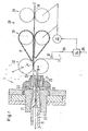
- FIG. 1 shows an exemplary embodiment of a spinning station of air-spinning machines for carrying out the inventive method.
- This spinning station is equipped for a so-called air spinning process with refinement by stretching.
- the spinning station has a means 3 for air twist distribution with a nozzle block 21 with nozzles 22 embedded therein, a spindle 23 with a yarn channel 24 and a feed block 25 with a fiber feed channel 26 and a needle 27 directed against the entrance of the yarn channel 24.
- the spinning station as a refinement unit on a drafting system 28 with, for example, three pairs of cylinders (inlet cylinder 29, central cylinder 30 with straps 31 and outlet cylinder 32 with nip 11).
- the inlet of the drafting device 28, so for example, the inlet cylinder 29 and the central cylinder 30 with straps 31 are driven by a motor 33.
- the motor 33 is controllable by a control unit 34.
- the control unit 34 uses for the control of the motor 33, a ready signal 35 and a yarn end signal 36 for determining the exact position of the end 2 of the yarn end 1 of a yarn end sensor 37, and spinning unit-own parameters.
- the fiber longitudinal formation 10 'fed in the feed direction Z enters into the refinement between the inlet cylinders 29, and becomes entangled with a usually constant draw ratio between inlet cylinders 29 and center cylinders 30 and between a central cylinders 30 and outlet cylinders 32 subjected to an optionally variable draw ratio.
- the refined fiber elongate structure 10 is drawn from the discharge cylinders 32 through the fiber supply channel 26 against the entrance of the yarn channel 24.
- Compressed air supplied by the nozzles 22 generates, in addition to the aforementioned suction effect in the region of the yarn channel entrance, a swirling flow which serves for the swirl distribution.
- the yarn 11 produced by this twist distribution is drawn off through the yarn channel 24 in withdrawal direction Z (means for yarn withdrawal).
- the motor 33 is first stopped, while the discharge cylinder 32 continue at least for a limited period.
- the supplied fiber longitudinal structure 10 ' is torn between the straps 31 and the outlet cylinders 32 and the downstream piece is conveyed away from the drafting arrangement by the outlet cylinders 32.
- the downstream piece is possibly disposed of thereon, the means for twist distribution 3 is possibly cleaned.
- the upper or lower part of the feed block 25 and the upper or lower of the discharge cylinder 32 can be lifted from their working position, such that the fiber feed channel 26 and the passage between the discharge cylinders 32 for a return and positioning of the yarn end 1 becomes accessible.
- the yarn end 1, which is unwound from the yarn package or may be an auxiliary yarn (bobbin change) is retracted or returned in such a spinning station for the resumption of the spinning process into the main delay region between center cylinders 30 and 31 and run-out cylinders 32 and hangs freely around the lower of the discharge cylinders 32, where it is monitored by the yarn end sensor 37 (in particular its end 2).
- the piecing process is carried out in a spinning station, as described in the FIG. 1 If the yarn end 1 is positioned and all the relevant parts of the spinning station are repositioned in their working position, the control unit 34, for example, by personnel or by a piecing robot, the ready signal 35 is transmitted. The control unit then starts the piecing process. That is, the twisting of the means for air twist distribution 3 and the yarn withdrawal (optionally with a predetermined staggering), so that the yarn end 1 begins to move against the twist distribution point. As soon as the yarn end sensor 37 detects the passage of the effective yarn end 2, the control unit receives the yarn end signal 36, by which the actual piecing routine is started.
- the motor 33 brings the pairs of rollers 30 and 29 within a very short time (hundredths of seconds) to a synchronized with the discharge cylinders 32 speed, so that at the time of overlap of the first fibers of the end portions of yarn end 1 and fiber elongated 10 'the rollers already in the correct speed ratio to each other rotate.
- the rolls may already have the appropriate nominal or operating speed (ie, the speed of the normal, stationary spinning process) at the beginning of the piecing or piecing process just explained. But it is also conceivable that the piecing or piecing takes place at a lower speed level. Whereupon, after piecing, all the rotating rolls of the refinement unit rise synchronously to their respective nominal or operating speed (eg on a ramp with a gearbox).
- nominal or operating speed ie, the speed of the normal, stationary spinning process
- control unit 34 For such a piecing routine, it is at most necessary for the control unit 34 to also provide data relating to the starting profile of the outlet cylinders 32, the central cylinders 30 and inlet cylinders 29, and the yarn take-off (not shown) and, if appropriate, measurement data from correspondingly arranged rotational speed sensors.
- the swirl pitch of the means 3 that is, in the present case, the speed of the air supplied from the nozzles 22 for the production of the Ansetzstelle compared to the normal spinning process changed, for example, be increased for a stronger Faserverwirbelung.
- the upstream of an air twist distribution in a spinning unit drafting system 28 may also have only two or more than three pairs of cylinders, wherein at a spinning break an inlet-side part of the cylinder pairs is stopped in front of an outlet side part of the cylinder pairs. In this case, after the spinning interruption, at least the inlet-side part of the cylinder pairs is retarded after a predetermined or determined based on sensor signals ramp.
- FIG. 1 represent the center cylinder 30 and inlet cylinder 29 the inlet side (by motor 33) drivable part of the refinement unit (here drafting system 28), while the outlet cylinder 32 represent the outlet side drivable parts.
- the position from the end of the yarn end is detected by means and transmitted to a control, which retards the startup of the inlet side driven part of the refinement unit in such a time when resuming the production of the yarn that the end portions of the torn fiber longitudinal structure and the yarn overlap over a predetermined length ,
- the length of the overlapping end regions substantially corresponds to the spinning distance d of the spinning station (see FIG. 1 ).
- the spinning distance d is defined as the distance between the mouth of the spindle 23 and the nip or clamping point 11 of the outlet cylinder 32nd
- this length of the overlapping end regions is also possible for this length of the overlapping end regions to be longer than the abovementioned spinning distance d of the spinning station.
- the end region of the yarn end 1 to be overlapped is roughened or tapered.
- the spinning station equipped for carrying out the method according to the invention has internal spinning stations its own controllable drive for the inlet-side parts of the refining agent or a correspondingly controllable transmission between these inlet-side parts of the refining means and a central drive.
- the other parts of the spinning unit to be driven can be driven by simple coupling to central drives or also by internally spinning, optionally controllable drives.
- the invention also includes a spinning station according to the invention of an air-spinning machine. This corresponds constructively to the embodiment according to FIG. 1 , why at this point to the description of FIG. 1 is referred back.
- the spinning unit according to the invention comprises a refinement unit (drafting unit) with parts which can be driven on the inlet side and outlet side, wherein at least the part which can be driven on the outlet side is equipped with at least one clamping point.
- the apparatus comprises means for air twisting, a means for yarn withdrawal, with a means for detecting the position of the end of a yarn end.
- the part of the refinement unit driven downstream can be opened in such a way that its clamping point or clamping points are exposed for a return and positioning of the yarn end.
- the outlet-side driven part consists of at least one outlet cylinder pair (32), wherein the upper or the lower cylinder of the outlet cylinder pair can be lifted (see arrow and dashed roller in FIG. 1 ).
- the means for air twist distribution (3) has an effective twist stop (27) for the yarn end.
- a mandrel 27 is shown here.
- the special feature is that the twist stop (27) is effective for the yarn end and not only for the fiber longitudinal structure. This results in very good piecing.
Description
Die Erfindung liegt auf dem Gebiete der Spinnereitechnik und betrifft ein Verfahren nach dem Oberbegriff des ersten Patentanspruchs. Das erfindungsgemässe Verfahren dient zum Ansetzen eines Garnes, das in einer Spinnmaschine bzw. in einer Spinnstelle einer Luftspinnmaschine aus einem Stapelfasermaterial gebildet wird, beispielsweise nach einem Kannenwechsel, nach einem Spulenwechsel, nach einem Garnbruch oder nach einer anderen Spinnstörung. Das Verfahren kann ebenfalls zum Anspinnen dienen, das heisst für den Neustart eines Spinnvorganges. Die Erfindung betrifft ferner eine für die Durchführung des erfindungsgemässen Verfahrens ausgerüstete Spinnstelle nach dem Oberbegriff des entsprechenden unabhängigen Patentanspruchs.The invention is in the field of spinning technology and relates to a method according to the preamble of the first claim. The inventive method is used to prepare a yarn which is formed in a spinning machine or in a spinning unit of an air spinning machine from a staple fiber material, for example after a can change, after a bobbin change, after a yarn breakage or after another spinning failure. The method can also serve for piecing, that is, for the restart of a spinning process. The invention further relates to a spinning station equipped for carrying out the method according to the invention according to the preamble of the corresponding independent patent claim.
Unter Luftspinnmaschinen ist insbesondere eine Vorrichtung zu verstehen zur Herstellung eines gesponnenen Fadens aus einem Faserverband umfassend einen Faserführungskanal mit einer Faserführungsfläche zur Führung der Fasern des Faserverbands in eine Einlassmündung eines Garnführungskanals, weiter umfassend eine Fluideinrichtung zur Erzeugung einer Wirbelströmung um die Einlassmündung des Garnführungskanals und der erfindungsgemässen Massnahme zur Beeinflussung der Strömungsverhältnisse im Spindelkanal einer stationären Spindel.Air-jet spinning machines are in particular a device for producing a spun yarn from a fiber structure comprising a fiber guide channel with a fiber guide surface for guiding the fibers of the fiber assembly in an inlet mouth of Garnführungskanals, further comprising a fluid means for generating a vortex flow around the inlet mouth of Garnführungskanals and the inventive Measure for influencing the flow conditions in the spindle channel of a stationary spindle.
Luftspinnmaschinen zum Verspinnen von Stapelfasermaterialien weisen üblicherweise eine gross Zahl von Spinnstellen auf, wobei in jeder Spinnstelle aus einem zugeführten Faserlängsgebilde ein Garn gesponnen wird. Dabei wird das Faserlängsgebilde zuerst verfeinert, das heisst, die Fasermenge pro Längeneinheit wird durch Verzug verkleinert. Dann wird der verfeinerte Faserverband durch Drallerteilung zu einem Garn versponnen, welches Garn dann abgezogen und aufgespult wird. Für die Verfeinerung wird das Faserlängsgebilde beispielsweise mittels Streckwerk gestreckt oder mit Hilfe einer Auflösewalze aufgelöst. Für die Garnbildung durch Drallerteilung wird eine Luftspinn-Methode verwendet, d.h die Garnbildung geschieht durch Luft-Drallerteilung .Air-jet spinning machines for spinning staple fiber materials usually have a large number of spinning stations, wherein a yarn is spun in each spinning station from a fed longitudinal fiber structure. The fiber longitudinal structure is first refined, that is, the amount of fiber per unit length is reduced by delay. Then the refined fiber strand is spun by twisting into a yarn, which yarn is then peeled off and wound up. For refinement, the fiber longitudinal structure is stretched, for example, by means of a drafting device or dissolved by means of an opening roller. For yarn formation by twisting an air-spinning method is used, that is, the yarn formation is done by air-twist distribution.
Nach einem Unterbruch des Luftspinnvorganges, in dem die Verbindung zwischen dem gesponnenen Garn und dem zu verspinnenden, verfeinerten Faserverband (Faserlängsgebilde) abgebrochen wird, muss diese Verbindung wieder hergestellt werden, nicht nur, damit das erzeugte Garn unterbruchslos ist, sondern auch, damit der Spinnvorgang wieder gestartet werden kann. Für eine solche Wiederverbindung von Garn und Faserlängsgebilde wird insbesondere bei Luftspinnverfahren das durch den Unterbruch entstandene, freie Garnende entgegen der normalen Garnförderrichtung stromaufwärts durch die Drallerteilungsstelle hinausgezogen und positioniert. Dann wird der Garnabzug und die Luft-Drallerteilung wieder in Betrieb genommen und der freie Anfang des verfeinerten Faserlängsgebilde wird der Luft-Drallerteilung zugeführt, derart, dass sich während einer kurzen Übergangszeit der Endbereich des Garnes und der Anfangsbereich des Faserverbandes miteinander durch die Drallerteilungsstelle bewegen. Dabei werden durch die Drallerteilung die Fasern des Faserverbandes mit den Fasern des Garn-Endbereichs verwirbelt und der Anfangsbereich des Faserverbandes mit dem Endbereich des Garnes in einer Art Spleissung verbunden. Der Spinnvorgang ist damit wieder in Betrieb gesetzt.After an interruption of the air-spinning process, in which the connection between the spun yarn and the refined fiber structure (fiber longitudinal structure) to be spun is broken, this connection must be restored, not only so that the yarn produced is uninterrupted, but also so that the spinning process can be restarted. For such a reconnection of yarn and fiber longitudinal structures, the free yarn end resulting from the interruption, in particular in air-spinning processes, is pulled out and positioned upstream of the normal yarn conveying direction through the twist distribution point. Then, the yarn take-off and the air twist distribution are put back into operation and the free beginning of the refined fiber longitudinal formation is fed to the air twist distribution such that during a short transition time the end region of the yarn and the beginning region of the fiber structure move together through the twist distribution point. In this case, the fibers of the fiber structure are swirled by the twist distribution with the fibers of the yarn end region and the initial region of the fiber structure is bonded to the end region of the yarn in a kind of splice. The spinning process is thus put back into operation.
Beim Anspinnen, das heisst bei einem Neustart eines Spinnvorganges kann in derselben Weise vorgegangen werden, wobei anstelle des Endbereiches des vor dem Spinnunterbruch hergestellten Garnes ein Hilfsgarn zur Anwendung kommt.When piecing, that is to say at a restart of a spinning process, it is possible to proceed in the same way, whereby an auxiliary yarn is used instead of the end region of the yarn produced before the spinning interruption.
Damit die Ansetzstelle eine störungsfreie Fortsetzung des Spinnvorganges erlaubt, muss diese selbst und ihre Umgebung eine für diesen Zweck genügend grosse Reissfestigkeit aufweisen, das heisst üblicherweise, dass diese Reissfestigkeit mindestens so gross sein soll, wie die Reissfestigkeit des im vorliegenden Spinnvorgang hergestellten Garnes.So that the Ansetzstelle allows a trouble-free continuation of the spinning process, this itself and its environment must have a sufficient tear strength for this purpose, that is usually that this tensile strength should be at least as large as the tensile strength of the yarn produced in the present spinning process.
Es sind verschiedene Methoden bekannt, um eine genügende Reissfestigkeit der Ansetzstelle zu erhalten. Diese Methoden greifen am freien Garnende, am freien Anfang des verfeinerten Faserverbandes und/oder an der zeitlichen Abstimmung der Bewegung des Garn-Endbereichs und des Faserverband-Anfangsbereichs durch die Drallerteilung an.There are various methods known to obtain a sufficient tensile strength of the Ansetzstelle. These methods will attack at the free end of the yarn, at the free beginning of the refined fiber strand and / or at the timing of the movement of the yarn end region and fiber strand starting region through the twist distribution.
Es ist beispielsweise aus der Publikation
Aus derselben Publikation ist es auch bekannt, den Garn-Endbereich derart für die Spleissung vorzubereiten, dass die Fasermasse gegen das Garnende allmählich abnimmt, dass das Garn sich also gegen sein Ende hin verjüngt. Ein derartig sich verjüngender Garn-Endbereich wird dann für die Spleissung mit einem entsprechend verjüngten Anfang eines Faserlängsgebildes (allmählich zunehmende Fasermasse) überlappend durch die Drallerteilungsstelle geführt.It is also known from the same publication to prepare the yarn end region for splicing in such a way that the fiber mass gradually decreases towards the yarn end, so that the yarn tapers towards its end. Such a tapering yarn end region is then passed through the twist distribution point for splicing with a correspondingly tapered beginning of a longitudinal fiber structure (gradually increasing fiber mass).
Die Verwendung eines "zugespitzten" Anfangsbereichs eines Faserverbandes für das Ansetzen ist beispielsweise beschrieben in der Publikation
Die Methode gemäss
Es zeigt sich, dass es schwierig ist, mit den genannten Methoden Ansetzstellen zu erstellen, die den Ansprüchen genügen können. Die nach den genannten Methoden angesetzten Garne tendieren unmittelbar nach einer Ansetzstelle eine Schwachstelle mit einer zu kleinen Fasermasse aufzuweisen. Aus diesem Grunde wird üblicherweise der Ansetzstelle mit einer gegenüber dem restlichen Garn bis zu 200% erhöhten Fasermasse eine für das Anspinnen sicher genügende Reissfestigkeit gegeben.It turns out that it is difficult to create with the above methods Ansetzstellen that can meet the requirements. The used according to the methods mentioned yarns tend to have a weak point with a too small fiber mass immediately after a piecing. For this reason, usually the Ansetzstelle is given with a comparison with the rest of the yarn up to 200% increased fiber mass sure for piecing tensile strength.
Mit diesem Problem befasst sich auch eine ältere europäische Anmeldung der Anmelderin (
Nebst der Ansetzerqualität (Festigkeit des Ansetzstelle), haben die Ansetz- oder Anspinnverfahren des Stand der Technik noch einen weiteren Nachteil. Bei diesen Verfahren gelingt der Ansetzvorgang nicht immer, so dass der Anteil an misslungenen Ansetzvorgängen auf die gesamte Anzahl von versuchten Ansetzvorgängen verhältnismässig hoch sein kann.In addition to the piecing quality (firmness of the piecing point), the piecing or piecing methods of the prior art still have a further disadvantage. In these methods, the piecing does not always succeed, so that the proportion of failed piecing on the total number of attempted piecing operations can be relatively high.
Die Aufgabe der Erfindung ist es nun, ein Verfahren zum Ansetzen oder Anspinnen zu schaffen, welches eine hohe Erfolgswahrscheinlichkeit des Ansetzvorganges aufweist und mit dem die Qualität der Ansetzstellen, insbesondere die Reissfestigkeit, verbessert wird.The object of the invention is now to provide a method for setting or piecing, which has a high probability of success of the piecing process and with the quality of Ansetzstellen, in particular the tensile strength is improved.
Diese Aufgabe wird gelöst durch das Verfahren gemäss dem unabhängigen Hauptanspruch gelöst.This object is achieved by the method according to the independent main claim.
Das erfindungsgemässe Verfahren beruht auf der Erkenntnis, dass die Chancen einen erfolgreichen Ansetzvorgang zu erhalten wesentlich höher sind, wenn die sich überlappenden Endbereiche des Garnendes und des zerrissenen Faserlängsgebildes im überlappenden Zustand zusammengepresst werden. Durch das Zusammenpressen der Fasern von Garnende und Faserlängsgebilde (d.h. Faserverband) werden die dazwischen wirkenden Reibungskräfte (d.h. Haftreibungskräfte) erhöht. Dieser erhöhte Zusammenhalt der Endbereiche wirkt sich positiv auf den folgenden Ablauf des Ansetzvorganges aus. Insbesondere wird die Wahrscheinlichkeit reduziert, dass sich die so "zusammengelöteten" Endbereiche vor dem Mittel zur Drallerteilung oder im Mittel, z.B. während der Drallerteilung mittels Luft, wieder trennen und der Ansetzvorgang dadurch misslingt. Die Prozesssicherheit des Ansetz- oder Anspinnvorganges und damit auch die Prozesssicherheit der Luftspinnmaschine wird dadurch erhöht.The method according to the invention is based on the recognition that the chances of obtaining a successful piecing process are substantially higher if the overlapping ones are successful End portions of the yarn end and the torn fiber longitudinal structure are pressed together in the overlapping state. By compressing the fibers of the yarn end and longitudinal fiber structures (ie fiber strand), the intervening frictional forces (ie, static friction forces) are increased. This increased cohesion of the end regions has a positive effect on the subsequent course of the piecing process. In particular, the likelihood is reduced that the so-called " soldered-together" end regions separate before the means for imparting twist or on average, for example during the impulse distribution by means of air, and the attaching process thereby fails. The process reliability of the piecing or piecing process and thus also the process reliability of the air spinning machine is thereby increased.
Darüber hinaus hat sich überraschenderweise gezeigt, dass auch die Ansetzerqualität bezüglich Reissfestigkeit erhöht wird. Damit ist es nicht mehr notwendig, dass der Ansetzer bzw. die Ansetzstelle für eine genügende Reissfestigkeit eine gegenüber dem restlichen Garn bis zu 200% erhöhten Fasermasse aufweist. Der Ansetzer weist damit eine wesentlich geringere Dickstelle auf. Dank der Reissfestigkeit kann auch die Länge der Ansetzstelle kürzer gewählt werden. Dadurch dass sowohl die Fasermasse als auch die Länge des Ansetzers geringer wird, werden gesamthaft auch die Nachteile, welche mit einem Ansetzer verbunden sind, verringert.In addition, it has surprisingly been found that the piecing quality is increased with respect to tear strength. Thus, it is no longer necessary that the piecing or the Ansetzstelle for a sufficient tear strength has compared to the remaining yarn up to 200% increased fiber mass. The piecing thus has a much smaller thickness. Thanks to the tensile strength, the length of the placement can be chosen shorter. The fact that both the fiber mass and the length of the piecing is reduced, the disadvantages which are associated with a piecing, are reduced overall.
Das Zusammenpressen der sich überlappenden Endbereiche des Garnendes und des zerrissenen Faserlängsgebildes wird bevorzugt durch die vorhandenen Möglichkeiten realisiert, d.h. ohne zusätzliche Vorrichtungen. Dazu geignet ist insbesondere die Klemmstelle des auslaufseitig angetriebenen Teiles der Verfeinerungseinheit (z.B. Auslaufwalzenpaar im Hauptverzug des Streckwerks). Grundsätzlich wäre es gemäss der Erfindungsidee aber auch möglich für den Ansetzvorgang eine spezielle Klemmoder Pressvorrichtung vorzusehen, welche das Garnende und das zerrissene Faserlängsgebilde zusammenpresst.The compression of the overlapping end portions of the yarn end and the torn fiber longitudinal structure is preferably realized by the existing possibilities, i. without additional devices. Particularly suitable for this purpose is the clamping point of the downstream-driven part of the refinement unit (for example pair of outfeed rollers in the main drafting of the drafting system). In principle, according to the idea of the invention, it would also be possible for the piecing process to provide a special clamping-type pressing device which compresses the yarn end and the torn fiber longitudinal structure.
Als günstig, aber nicht unbedingt notwendig, hat sich auch die Variante herausgestellt, das Garnende bzw. dessen zu überlappenden Endbereich aufzurauhen oder zu verjüngen, z.B. mit einer Vorrichtung gemäss
Das erfindungsgemässe Verfahren und deren Vorrichtung wird nun anhand eines Ausführungsbeispieles erläutert. Das Ausführungsbeispiel wird anhand der
Der Einlauf des Streckwerkes 28, also beispielsweise die Einlaufzylinder 29 und die Mittelzylinder 30 mit Riemchen 31, werden durch einen Motor 33 angetrieben. Der Motor 33 ist von einer Steuereinheit 34 steuerbar. Die Steuereinheit 34 verwertet zur Steuerung des Motors 33 ein Bereitschaftssignal 35 und ein Garnende-Signal 36 für die Bestimmung der genauen Position des Endes 2 des Garnendes 1 eines Garnende-Sensors 37, sowie Spinnstellen-eigene Parameter.The inlet of the
Während des an sich bekannten Spinnprozesses in der Spinnstelle gemäss
Bei einer Unterbrechung des Spinnprozesses, zum Beispiel bei Garnbruch oder Spulenwechsel, wird zuerst der Motor 33 gestoppt, während die Auslaufzylinder 32 mindestens für einen begrenzten Zeitraum weiterlaufen. Dadurch wird das zugeführte Faserlängsgebilde 10' zwischen den Riemchen 31 und den Auslaufzylindern 32 zerrissen und das stromabwärts liegende Stück durch die Auslaufzylinder 32 aus dem Streckwerk weggefördert. Das stromabwärts liegende Stück wird darauf allenfalls entsorgt, wobei das Mittel zur Drallerteilung 3 allenfalls gereinigt wird.In an interruption of the spinning process, for example, yarn break or bobbin change, the
Für die Positionierung des freien Garnendes nach einer Unterbrechung des Spinnprozesses sind beispielsweise der obere oder untere Teil des Zuführungsblocks 25 und der obere oder untere der Auslaufzylinder 32 von ihrer Arbeitsposition abhebbar, derart, dass der Faserzuführungskanal 26 und der Durchgang zwischen den Auslaufzylindern 32 für eine Rückführung und Positionierung des Garnendes 1 zugänglich wird. Das Garnende 1, welches von der Garnspule abgewickelt wird oder ein Hilfsgarn (bei Spulenwechsel) sein kann, wird in einer derart ausgerüsteten Spinnstelle für die Wiederaufnahme des Spinnprozesses bis in den Hauptverzugsbereich zwischen Mittelzylindern 30 bzw. Riemchen 31 und Auslaufzylindern 32 zurückgezogen bzw. rückgeführt und hängt frei um den unteren der Auslaufzylinder 32, wo er vom Garnende-Sensor 37 überwacht wird (insbesondere dessen Ende 2). Bei der Rückführung durch den Düsenblock 21 bzw. Garnkanal können Hilfsmittel, z.B. eine Saugvorrichtung, verwendet werden. Bei der anschliessenden Positionierung des Garnendes 1 auf den Auslaufzylindern 32 ist darauf zu achten, dass das Garnende 1 mit dem Faserlängsgebilde 10' fluchtend angeordnet ist, insbesondere in der Klemmstelle 11 (in der Ansicht von
Das Anspinnverfahren wird in einer Spinnstelle, wie sie in der
Für eine solche Anspinnroutine ist es allenfalls notwendig, dass der Steuereinheit 34 auch Daten bezüglich des Anfahrprofils der Auslaufzylinder 32, der Mittelzylinder 30 und Einlaufzylinder 29, sowie des Garnabzuges (nicht dargestellt) zur Verfügung zu stellen und gegebenenfalls Messdaten von entsprechend angeordneten Drehzahlsensoren.For such a piecing routine, it is at most necessary for the
Gegebenenfalls kann die Drallerteilung des Mittels 3, das heisst im vorliegenden Fall die Geschwindigkeit der aus den Düsen 22 zugeführten Luft für die Herstellung der Ansetzstelle gegenüber dem normalen Spinnprozess verändert, beispielsweise für eine stärkere Faserverwirbelung erhöht werden.Optionally, the swirl pitch of the means 3, that is, in the present case, the speed of the air supplied from the
Das einer Luft-Drallerteilung in einer Spinnstelle vorgeschaltete Streckwerk 28 kann auch nur zwei oder mehr als drei Zylinderpaare aufweisen, wobei bei einer Spinnunterbrechung ein einlaufseitiger Teil der Zylinderpaare vor einem auslaufseitigen Teil der Zylinderpaare gestoppt wird. Dabei wird nach dem Spinnunterbruch mindestens der einlaufseitige Teil der Zylinderpaare nach einer vorgegebenen oder anhand von Sensorsignalen ermittelten Rampe verzögert hochgefahren. In der
Für das erfindungsgemässe Anspinn- oder Ansetzverfahren für Spinnstellen von Luftspinnmaschinen, welche in einem Spinnprozess aus einem Faserlängsgebilde ein Garn herstellen, werden benötigt: Eine Verfeinerungseinheit (z.B. ein Streckwerk) mit einlaufseitig (z.B. ein Vorverzug) und auslaufseitig (z.B. ein Hauptverzug) antreibbaren Teilen, wobei zumindest das auslaufseitig antreibbaren Teil ein Klemmstelle aufweist. Ein Mittel zur Luft-Drallerteilung (Vortex) und ein Mittel zum Garnabzug. Die erfindungsgemässen Verfahren weisen nach einem Unterbruch des Spinnprozesses für die Wiederaufnahme der Herstellung des Garnes die folgenden - in dieser Reihenfolge durchzuführende - Schritte auf (wobei von einem Stillstand bei sämtlichen Bauteilen ausgegangen wird):
- Inbetriebnahme der Verfeinerungseinheit (z.B. Streckwerk) mit den einlaufseitig (z.B. Einlaufzylinder und Mittelzylinder mit Riemchen) und auslaufseitig antreibbaren Teilen (z.B. Auslaufzylinder),
- Zerreissen des Faserlängsgebilde durch Abstellen des Antriebes des einlaufseitig angetriebenen Teiles (Einlauf- und Mittelzylinder) und erst anschliessendem Abstellen des auslaufseitig angetriebenen Teiles (Auslaufzylinder), wobei das Faserlängsgebilde dadurch an einer ziemlich genau durch Versuche bestimmbaren Stelle zwischen beiden Teilen reisst.
- Rückführung eines Garnendes an welchem Angesponnen oder Angesetzt werden soll zuerst durch das Mittel zum Garnabzug, dann durch das Mittel zur Drallerteilung (z.B. Mittel 3) und schliesslich durch das auslaufseitig angetriebene Teil (Auslaufzylinder des Streckwerks)
- Feststellen der Position vom Ende des Garnendes oder Mittel um Festzustellen, wann das Ende des Garnendes eine vorbestimmte Position erreicht hat.
- Inbetriebnahme des Mittels zur Luft-Drallerteilung (z.B. Mittel 3), des Mittels zum Garnabzug und der ein- sowie auslaufseitig angetriebenen Teile der Verfeinerungseinheit
- Die Rückführung des Garnendes durch das auslaufseitig angetriebenen Teil der Verfeinerungseinheit durch Öffnen des auslaufseitig angetriebenen Teiles der Verfeinerungseinheit geschieht mit anschliessender
- Positionierung des Garnendes im auslaufseitig angetriebenen Teil der Verfeinerungseinheit fluchtend mit dem Faserlängsgebilde im einlaufseitig angetriebenen Teil.
- Schliessen des auslaufseitig angetriebenen Teiles der Verfeinerungseinheit.
- Die Inbetriebnahme des auslaufseitig angetriebenen Teiles der Verfeinerungseinheit, verbunden mit einem Abzug des Garnendes durch den auslaufseitig angetriebenen Teil (Auslaufzylinder),
- gefolgt von einer zeitlich abgestimmten und verzögerten Inbetriebnahme des einlaufseitig angetriebenen Teiles ist, derart dass sich die Endbereiche des zerrissenen Faserlängsgebilde und des Garnendes überlappen und im überlappenden Zustand die Klemmstelle des auslaufseitig angetriebenen Teiles passieren.
- Commissioning of the refinement unit (eg drafting system) with the inlet side (eg inlet cylinder and center cylinder with straps) and parts which can be driven on the outlet side (eg outlet cylinder),
- Tearing of the fiber longitudinal structure by stopping the drive of the inlet side driven part (inlet and center cylinder) and only subsequent shutdown of the outlet side driven part (discharge cylinder), the fiber longitudinal structure thereby tears at a location determinable by experiments exactly between the two parts.
- Returning a yarn end to which it is intended to be wound or applied first by the means for yarn withdrawal, then by the means for swirl distribution (eg means 3) and finally by the outlet-side driven part (discharge cylinder of the drafting system)
- Detecting the position from the end of the yarn end or means to determine when the end of the yarn end has reached a predetermined position.
- Commissioning of the means for air-twist distribution (eg means 3), the means for Garnabzug and the inlet and outlet side driven parts of the refinement unit
- The return of the yarn end by the outlet side driven part of the refinement unit by opening the outlet side driven part of the refinement unit is done with subsequent
- Positioning of the yarn end in the outlet side driven part of the refinement unit in alignment with the longitudinal fiber structure in the inlet side driven part.
- Closing the downstream driven part of the refinement unit.
- The commissioning of the downstream driven part of the refinement unit, connected to a deduction of the yarn end by the outlet side driven part (discharge cylinder),
- followed by a timed and delayed start-up of the intake-side driven part, such that the end regions of the torn fiber longitudinal formation and the yarn end overlap and in the overlapping state pass through the nip of the outlet-side driven part.
Es ist klar, dass diese Schritte in der oben angegebenen Reihenfolge durchzuführen sind. Die Erfindung ist aber nicht auf diese Reihenfolge beschränkt, z.B. kann der Schritt "Feststellen der Position vom Ende des Garnendes" zu verschiedenen Zeitpunkten erfolgen. Auch sind die ersten beiden Schritte:
- Inbetriebnahme der Verfeinerungseinheit (z.B. Streckwerk) mit den einlaufseitig (z.B. Einlaufzylinder und Mittelzylinder mit Riemchen) und auslaufseitig antreibbaren Teilen (z.B. Auslaufzylinder),
- Zerreissen des Faserlängsgebilde durch Abstellen des Antriebes des einlaufseitig angetriebenen Teiles (Einlauf- und Mittelzylinder) und erst anschliessendem Abstellen des auslaufseitig angetriebenen Teiles (Auslaufzylinder), wobei das Faserlängsgebilde dadurch an einer ziemlich genau durch Versuche bestimmbaren Stelle zwischen beiden Teilen reisst,
Diese beiden Schritte müssen also dem Ansetzvorgang vorgegangen sein.It is clear that these steps are to be performed in the order given above. However, the invention is not limited to this order, for example, the step "detecting the position of the end of the yarn end" can be done at different times. Also, the first two steps are:
- Commissioning of the refinement unit (eg drafting system) with the inlet side (eg inlet cylinder and center cylinder with straps) and parts which can be driven on the outlet side (eg outlet cylinder),
- Tearing of the fiber longitudinal structure by stopping the drive of the inlet side driven part (inlet and center cylinder) and only subsequent shutdown of the outlet side driven part (outlet cylinder), the fiber longitudinal structure thereby tears at a determinable by experiments place between both parts,
These two steps must therefore have proceeded to the piecing process.
Erfindungsgemäß wird die Position vom Ende des Garnendes durch Mittel erfasst und einer Steuerung übermittelt, welche bei Wiederaufnahme der Herstellung des Garnes die Inbetriebnahme des einlaufseitig angetriebenen Teiles der Verfeinerungseinheit zeitlich derart verzögert, dass die Endbereiche des zerrissenen Faserlängsgebilde und des Garnendes sich auf einer vorgegeben Länge überlappen.According to the invention, the position from the end of the yarn end is detected by means and transmitted to a control, which retards the startup of the inlet side driven part of the refinement unit in such a time when resuming the production of the yarn that the end portions of the torn fiber longitudinal structure and the yarn overlap over a predetermined length ,
Erfindungsgemäß entspricht die Länge der sich überlappenden Endbereiche im wesentlichen der Spinndistanz d der Spinnstelle (siehe
Es ist auch möglich, dass diese Länge der sich überlappenden Endbereiche länger ist als die genannte Spinndistanz d der Spinnstelle.It is also possible for this length of the overlapping end regions to be longer than the abovementioned spinning distance d of the spinning station.
In einer weiteren Variante der Erfindung ist der zu überlappende Endbereich des Garnendes 1 aufgerauht oder verjüngt.In a further variant of the invention, the end region of the yarn end 1 to be overlapped is roughened or tapered.
Die für die Durchführung des erfindungsgemässen Verfahrens ausgerüstete Spinnstelle weist Spinnstellen-intern einen eigenen, steuerbaren Antrieb für die einlaufseitigen Teile des Verfeinerungsmittels oder ein entsprechend ansteuerbares Getriebe zwischen diesen einlaufseitigen Teilen des Verfeinerungsmittels und einem zentralen Antrieb auf.The spinning station equipped for carrying out the method according to the invention has internal spinning stations its own controllable drive for the inlet-side parts of the refining agent or a correspondingly controllable transmission between these inlet-side parts of the refining means and a central drive.
Die weiteren anzutreibenden Teile der Spinnstelle können durch einfache Ankoppelung an zentrale Antriebe oder ebenfalls durch Spinnstellen-interne, gegebenenfalls ansteuerbare Antriebe angetrieben sein.The other parts of the spinning unit to be driven can be driven by simple coupling to central drives or also by internally spinning, optionally controllable drives.
Die Erfindung umfasst auch eine erfindungsgemässe Spinnstelle einer Luftspinnmaschine. Diese entspricht konstruktiv dem Ausführungsbeispiel gemäss
In einer bevorzugten Ausführungsform der Erfindung besteht das auslaufseitig angetriebenen Teil aus mindestens einem Auslaufzylinderpaar (32), wobei der obere oder der untere Zylinder des Auslaufzylinderpaares abhebbar ist (siehe Pfeil und gestrichelte Walze in
In einer weiteren Ausführungsform der Erfindung kann vorgesehen werden, dass das Mittel zur Luft-Drallerteilung (3) einen für das Garnende wirksamen Drallstopp (27) aufweist. Als Beispiel wird hier ein Dorn 27 gezeigt. Die Besonderheit ist, dass der Drallstopp (27) für das Garnende wirksam ist und nicht nur für das Faserlängsgebilde. Dadurch ergeben sich besonders gute Ansetzer.
In den Ansprüchen sind weitere Ausführungsformen der Erfindung aufgeführt.The invention also includes a spinning station according to the invention of an air-spinning machine. This corresponds constructively to the embodiment according to
In a preferred embodiment of the invention, the outlet-side driven part consists of at least one outlet cylinder pair (32), wherein the upper or the lower cylinder of the outlet cylinder pair can be lifted (see arrow and dashed roller in
In a further embodiment of the invention it can be provided that the means for air twist distribution (3) has an effective twist stop (27) for the yarn end. As an example, a
In the claims further embodiments of the invention are listed.
Es wäre auch denkbar, dass anstelle der Klemmstelle 11 der Auslaufzylinder 32 eine zusätzliche Vorrichtung die Funktion der Klemmstelle, d.h. das Zusammenpressen der überlappenden Endbereiche von Garnende (1) und Faserlängsgebilde (10'), für den Ansetzvorgang übernimmt. Eine solche Vorrichtung wäre anschliessend wegschwenkbar.It would also be conceivable that instead of the
Die Erfindung ist nicht auf die explizit genannten Möglichkeiten und Ausführungsformen beschränkt. Diese Varianten sind vielmehr als Anregung für den Fachmann gedacht, um die Erfindungsidee möglichst günstig umzusetzen. Von den beschriebenen Ausführungsformen sind daher leicht weitere vorteilhafte Anwendungen und Kombinationen ableitbar, die ebenfalls den Erfindungsgedanken wiedergeben und durch diese Anmeldung geschützt werden sollen.The invention is not limited to the explicitly stated possibilities and embodiments. These variants are intended rather as a suggestion for the expert to implement the idea of the invention as low as possible. Of the described embodiments, therefore, further advantageous applications and combinations are readily derivable, which also reflect the inventive concept and should be protected by this application.
Claims (4)
- Method for starting the spinning process or piecing-method for spinning positions of air spinning frames, which, during a spinning process, produce a thread (11) from a longitudinal fibre structure (10') and which, therefor, comprise a drafting unit (28) with drivable parts at the inlet side (30, 29) and at the outlet side (32) with clamping points (11), a means for generating an air twist (3) and a means for the thread take-off, whereby, after an interruption of the spinning process, the resumption of the production of the thread comprises the following steps,- return of a thread end (1) at which the spinning has to be started or the piecing has to take place, first by the means for the thread taking-off, then by the means for generating a twist (3) and finally by the driven part at the outlet side (32) of the drafting unit (28)- determination of the position of the end (2) of the thread end (1)- -starting-up of the means for generating the air twist (3), the means for the thread take-off and the parts of the drafting unit (28)- the return of the thread end (1) takes place through the driven part (32) at the outlet side of the drafting unit, by opening the driven part (32) of the drafting unit at the outlet side, whereby, afterwards the thread end (1) is positioned In the driven part (32) at the outlet side of the drafting unit driven In alignment with the longitudinal fibre structure (10') in the driven part at the inlet side, and afterwards- the driven part (32) at the outlet side of the drafting unit (28) is being closed again, and- the starting-up of the driven part (32) at the outlet side of the drafting unit (28) takes place with a subsequent time co-ordinated and delayed start-up of the driven parts (30, 29) at the inlet side, in such a manner that the end portions of the torn longitudinal fibre structure (10') and of the thread end (1) overlap and pass, in overlapping condition, the clamping point (11) of the driven part (32) at the outlet side,whereby the position of the end (2) of the thread end (1), being registered by means (37), is transmitted to a control unit (34), which, with the resumption of the production of the thread, delays the starting-up of driven the part (30, 28) of the drafting unit (28), at the inlet side, timed in such a manner that the end portions of the torn longitudinal fibre structure (10') and of the thread end (1) overlap over a predetermined length, characterized in that,
the length of the overlapping end portions essentially corresponds with the spinning distance (d) of the spinning position or the length of the overlapping end portions is longer than the spinning distance (d) of the spinning position, whereby, the spinning distance "d" is defined as the distance between the port of the spindle (23) and the clamping line or the clamping point (11) of the output cylinder (32). - Method according to claim 1, characterized in that the step, concerning the return of the thread end (1) at which the start of spinning or the piecing has to take place, is preceded by the following two steps- starting-up of the drafting unit (28) with the drivable parts (30, 29) at the inlet side and the drivable parts (32) at the outlet side,- tearing of the longitudinal fibre structure (10') by stopping the drive unit (33) of the driven part (30, 29) at the inlet side and only by subsequently stopping the driven part (32) at the outlet side.
- Spinning position of an air spinning frame containing a drafting unit (28) with drivable parts (29, 30) at the inlet side and drivable parts (32) at the outlet side , whereby at least the drivable part (32) at the outlet side is furnished with at least one clamping point (11), with a means for generating an air twist (3), a means for the thread taking-off, with a means (37) for the determination of the position of the end (2) of the thread end (1), characterized in that- the driven part (32) at the outlet side of the drafting unit (28) can be opened in such a manner, that its clamping point (11) or clamping points lies free for a return and a positioning of the thread end (1) and that the spinning position comprises a control means (34) for carrying out the start of the spinning or the method of piecing according to claim 1.
- Device according to claim 3, characterized in that the drafting unit (28) is a drafting unit and that the driven part (29, 30) at the inlet side realises a pre-draft and that the driven part (32) at the outlet side represents the outlet clamping line (11) of the drafting unit.
Applications Claiming Priority (2)
| Application Number | Priority Date | Filing Date | Title |
|---|---|---|---|
| CH10672002 | 2002-06-21 | ||
| CH10672002 | 2002-06-21 |
Publications (3)
| Publication Number | Publication Date |
|---|---|
| EP1375709A2 EP1375709A2 (en) | 2004-01-02 |
| EP1375709A3 EP1375709A3 (en) | 2004-05-12 |
| EP1375709B1 true EP1375709B1 (en) | 2014-08-06 |
Family
ID=29716493
Family Applications (1)
| Application Number | Title | Priority Date | Filing Date |
|---|---|---|---|
| EP03013347.4A Expired - Lifetime EP1375709B1 (en) | 2002-06-21 | 2003-06-16 | Piecing method for, or piecing of, spinning stations in Air vortex spinning machines |
Country Status (4)
| Country | Link |
|---|---|
| US (1) | US6959532B2 (en) |
| EP (1) | EP1375709B1 (en) |
| JP (1) | JP4718108B2 (en) |
| CN (1) | CN100379911C (en) |
Families Citing this family (17)
| Publication number | Priority date | Publication date | Assignee | Title |
|---|---|---|---|---|
| US6802353B2 (en) * | 2001-10-10 | 2004-10-12 | The Procter & Gamble Company | Apparatus for recycling waste from an absorbent article processing line |
| DE10335651B4 (en) * | 2003-07-29 | 2017-02-23 | Wilhelm Stahlecker Gmbh | Method and device for restoring an interrupted spinning process |
| US20090189319A1 (en) * | 2004-02-02 | 2009-07-30 | Kim Hak-Yong | Process of preparing continuous filament composed of nanofibers |
| EP1564317A1 (en) * | 2004-02-10 | 2005-08-17 | Maschinenfabrik Rieter Ag | Method for obtaining a pieced yarn lenght having constant mass in a vortex Spinning procedure |
| DE102004050968A1 (en) * | 2004-10-15 | 2006-04-20 | Wilhelm Stahlecker Gmbh | Method for preparing a piecing process on an air jet spinning device |
| CZ301752B6 (en) * | 2005-12-20 | 2010-06-16 | Rieter Cz S.R.O. | Method for recovery of component yarn spinning, particularly on rotor spinning machine, using a splicer, and apparatus for making the same |
| CN101294319B (en) * | 2008-05-26 | 2010-06-02 | 东华大学 | Spinning apparatus with air injection whirling current for lowering fibre |
| CN101565866B (en) * | 2009-04-17 | 2010-10-27 | 北京经纬纺机新技术有限公司 | Rotor spinning machine full automatic joint control method and device thereof |
| DE102011054302A1 (en) * | 2011-10-07 | 2013-04-11 | Maschinenfabrik Rieter Ag | Garnbildungselement for a spinning station of an air spinning machine with a twist stop element |
| CZ2013275A3 (en) * | 2013-04-09 | 2014-10-22 | Rieter Cz S.R.O. | Spinning staring method on spinning machine, particularly on air jet spinning machine or rotor spinning machine |
| CH709756A1 (en) * | 2014-06-13 | 2015-12-15 | Rieter Ag Maschf | Spinneret for a spinning machine and air jet spinning machine with a corresponding spinneret. |
| CH709953A1 (en) * | 2014-07-30 | 2016-02-15 | Rieter Ag Maschf | Method for operating an air spinning machine. |
| CZ2015321A3 (en) * | 2015-05-14 | 2016-12-21 | Rieter Cz S.R.O. | Method of mass yarn spinning on workstations of rotor spinning machine and apparatus for making the same |
| JP2017071865A (en) * | 2015-10-06 | 2017-04-13 | 村田機械株式会社 | Spinning machine |
| DE102018007464A1 (en) * | 2018-09-21 | 2020-03-26 | Saurer Spinning Solutions Gmbh & Co. Kg | Service trolley and method for automatically supplying spinning positions on a spinning machine |
| CN111519286B (en) * | 2020-04-28 | 2021-11-26 | 天津工业大学 | Multi-twist spinning device, multi-twist spinning equipment and spinning method |
| CN111778601B (en) * | 2020-06-29 | 2021-06-15 | 苏州优百纺织有限公司 | Automatic wire connector for broken wire |
Family Cites Families (8)
| Publication number | Priority date | Publication date | Assignee | Title |
|---|---|---|---|---|
| JPS5966527A (en) * | 1982-10-07 | 1984-04-16 | Toyoda Autom Loom Works Ltd | Yarn ending in bundle-binding spinning machine |
| US5339614A (en) | 1991-07-11 | 1994-08-23 | Maschinenfabrik Rieter Ag | Rotating disc for separating and processing the end of yarn |
| US5524427A (en) | 1992-11-10 | 1996-06-11 | Howa Machinery, Ltd. | Method and apparatus for piecing slivers in a spinning machine by throttling in a nozzle |
| KR100296977B1 (en) * | 1996-01-30 | 2001-11-22 | 무라타 기카이 가부시키가이샤 | Fishing method of spinning machine |
| TW341605B (en) | 1996-05-16 | 1998-10-01 | Murada Kikai Kk | Piecing method for a spinning machine |
| JP2973961B2 (en) | 1997-01-13 | 1999-11-08 | 村田機械株式会社 | Spinning machine piecing method and apparatus |
| EP1205588B1 (en) | 2000-11-08 | 2004-12-15 | Maschinenfabrik Rieter Ag | Control of several spinning stationes in a spinning machine |
| EP1219737B2 (en) * | 2000-12-22 | 2012-01-18 | Maschinenfabrik Rieter Ag | Procedure for piecing up or joining a yarn created in a spinning station, said spinning station being equiped to carry out the procedure |
-
2003
- 2003-06-16 EP EP03013347.4A patent/EP1375709B1/en not_active Expired - Lifetime
- 2003-06-18 US US10/464,054 patent/US6959532B2/en not_active Expired - Lifetime
- 2003-06-20 CN CNB031438822A patent/CN100379911C/en not_active Expired - Fee Related
- 2003-06-23 JP JP2003178317A patent/JP4718108B2/en not_active Expired - Fee Related
Also Published As
| Publication number | Publication date |
|---|---|
| EP1375709A2 (en) | 2004-01-02 |
| CN100379911C (en) | 2008-04-09 |
| EP1375709A3 (en) | 2004-05-12 |
| JP4718108B2 (en) | 2011-07-06 |
| JP2004027473A (en) | 2004-01-29 |
| US6959532B2 (en) | 2005-11-01 |
| US20040045270A1 (en) | 2004-03-11 |
| CN1477247A (en) | 2004-02-25 |
Similar Documents
| Publication | Publication Date | Title |
|---|---|---|
| EP1375709B1 (en) | Piecing method for, or piecing of, spinning stations in Air vortex spinning machines | |
| DE19501545C2 (en) | Process for starting a yarn in a spinning machine | |
| EP1219737B2 (en) | Procedure for piecing up or joining a yarn created in a spinning station, said spinning station being equiped to carry out the procedure | |
| EP1817448B1 (en) | Method for optimizing the output of a spinning frame | |
| EP2831319A1 (en) | Slubbing machine with an arrangement for detecting and removing yarn flaws | |
| DE3413894C2 (en) | ||
| WO1987003310A1 (en) | Process and device for rethreading a spinning device provided with a pneumatic twisting element | |
| DE3411577C2 (en) | ||
| DE3336294A1 (en) | Process for the piecing of yarn during the spinning of bunched-fibre yarns | |
| EP3276057A1 (en) | Filament guide unit of an open-end spinning machine and method for operating a spinning station | |
| DE10335651B4 (en) | Method and device for restoring an interrupted spinning process | |
| WO2006042686A1 (en) | Method for preparing an attachment operation for an air-jet spinning device | |
| DE3539383C2 (en) | ||
| DE3819858A1 (en) | DEVICE FOR GENERATING REELS FOR A TWISTING REEL | |
| WO1989010990A1 (en) | Process and device for starting spinning in an open-end spinning device | |
| DE10346194B4 (en) | Method and apparatus for recovering a suspended spinning operation | |
| EP0205962B1 (en) | Method for piecing a yarn in a friction-spinning apparatus | |
| CH685946A5 (en) | Method and apparatus for automatic application of a re-weaving the yarn to an existing yarn. | |
| EP1295974B1 (en) | Air jet spinning device with a fibre disintegrating apparatus | |
| DE1710021A1 (en) | Method and device for piecing the yarn in the event of yarn breakage or resumption of the interrupted spinning process during capsule spinning of textile yarns | |
| DE19514997A1 (en) | Slubbing feeding in and through spinner drawing unit for high draft | |
| WO2003018887A1 (en) | Method for handling a spinning device in case of yarn rupture | |
| EP3140233B1 (en) | Textile machine for producing a roving and method of starting roving production with such a textile machine | |
| DE10217243B4 (en) | Method for piecing a thread on an open-end spinning device | |
| DE102005045830A1 (en) | Repairing yarn breakages in an air-jet spinning machine comprises cutting a twisted join from the yarn and splicing the yarn ends before the yarn is wound onto a package |
Legal Events
| Date | Code | Title | Description |
|---|---|---|---|
| PUAI | Public reference made under article 153(3) epc to a published international application that has entered the european phase |
Free format text: ORIGINAL CODE: 0009012 |
|
| AK | Designated contracting states |
Kind code of ref document: A2 Designated state(s): AT BE BG CH CY CZ DE DK EE ES FI FR GB GR HU IE IT LI LU MC NL PT RO SE SI SK TR |
|
| AX | Request for extension of the european patent |
Extension state: AL LT LV MK |
|
| PUAL | Search report despatched |
Free format text: ORIGINAL CODE: 0009013 |
|
| AK | Designated contracting states |
Kind code of ref document: A3 Designated state(s): AT BE BG CH CY CZ DE DK EE ES FI FR GB GR HU IE IT LI LU MC NL PT RO SE SI SK TR |
|
| AX | Request for extension of the european patent |
Extension state: AL LT LV MK |
|
| RIC1 | Information provided on ipc code assigned before grant |
Ipc: 7D 01H 4/48 A Ipc: 7D 01H 4/02 B |
|
| 17P | Request for examination filed |
Effective date: 20041105 |
|
| AKX | Designation fees paid |
Designated state(s): CH CZ ES IT LI TR |
|
| RBV | Designated contracting states (corrected) |
Designated state(s): CH CZ DE ES IT LI TR |
|
| REG | Reference to a national code |
Ref country code: DE Ref legal event code: 8566 |
|
| RBV | Designated contracting states (corrected) |
Designated state(s): CH CZ DE ES IT LI TR |
|
| 17Q | First examination report despatched |
Effective date: 20071123 |
|
| GRAP | Despatch of communication of intention to grant a patent |
Free format text: ORIGINAL CODE: EPIDOSNIGR1 |
|
| INTG | Intention to grant announced |
Effective date: 20140116 |
|
| GRAS | Grant fee paid |
Free format text: ORIGINAL CODE: EPIDOSNIGR3 |
|
| GRAA | (expected) grant |
Free format text: ORIGINAL CODE: 0009210 |
|
| AK | Designated contracting states |
Kind code of ref document: B1 Designated state(s): CH CZ DE ES IT LI TR |
|
| REG | Reference to a national code |
Ref country code: CH Ref legal event code: EP |
|
| REG | Reference to a national code |
Ref country code: DE Ref legal event code: R096 Ref document number: 50315098 Country of ref document: DE Effective date: 20140918 |
|
| PG25 | Lapsed in a contracting state [announced via postgrant information from national office to epo] |
Ref country code: ES Free format text: LAPSE BECAUSE OF FAILURE TO SUBMIT A TRANSLATION OF THE DESCRIPTION OR TO PAY THE FEE WITHIN THE PRESCRIBED TIME-LIMIT Effective date: 20140806 |
|
| PG25 | Lapsed in a contracting state [announced via postgrant information from national office to epo] |
Ref country code: CZ Free format text: LAPSE BECAUSE OF FAILURE TO SUBMIT A TRANSLATION OF THE DESCRIPTION OR TO PAY THE FEE WITHIN THE PRESCRIBED TIME-LIMIT Effective date: 20140806 Ref country code: IT Free format text: LAPSE BECAUSE OF FAILURE TO SUBMIT A TRANSLATION OF THE DESCRIPTION OR TO PAY THE FEE WITHIN THE PRESCRIBED TIME-LIMIT Effective date: 20140806 |
|
| REG | Reference to a national code |
Ref country code: DE Ref legal event code: R097 Ref document number: 50315098 Country of ref document: DE |
|
| PLBE | No opposition filed within time limit |
Free format text: ORIGINAL CODE: 0009261 |
|
| STAA | Information on the status of an ep patent application or granted ep patent |
Free format text: STATUS: NO OPPOSITION FILED WITHIN TIME LIMIT |
|
| 26N | No opposition filed |
Effective date: 20150507 |
|
| REG | Reference to a national code |
Ref country code: CH Ref legal event code: PL |
|
| PG25 | Lapsed in a contracting state [announced via postgrant information from national office to epo] |
Ref country code: LI Free format text: LAPSE BECAUSE OF NON-PAYMENT OF DUE FEES Effective date: 20150630 Ref country code: CH Free format text: LAPSE BECAUSE OF NON-PAYMENT OF DUE FEES Effective date: 20150630 |
|
| PGFP | Annual fee paid to national office [announced via postgrant information from national office to epo] |
Ref country code: DE Payment date: 20210628 Year of fee payment: 19 |
|
| PGFP | Annual fee paid to national office [announced via postgrant information from national office to epo] |
Ref country code: TR Payment date: 20210610 Year of fee payment: 19 |
|
| REG | Reference to a national code |
Ref country code: DE Ref legal event code: R119 Ref document number: 50315098 Country of ref document: DE |
|
| PG25 | Lapsed in a contracting state [announced via postgrant information from national office to epo] |
Ref country code: DE Free format text: LAPSE BECAUSE OF NON-PAYMENT OF DUE FEES Effective date: 20230103 |