EP4327770A1 - Vorrichtung zur oralen einsetzung zur steuerung von energieübertragungseigenschaften - Google Patents
Vorrichtung zur oralen einsetzung zur steuerung von energieübertragungseigenschaften Download PDFInfo
- Publication number
- EP4327770A1 EP4327770A1 EP22791876.0A EP22791876A EP4327770A1 EP 4327770 A1 EP4327770 A1 EP 4327770A1 EP 22791876 A EP22791876 A EP 22791876A EP 4327770 A1 EP4327770 A1 EP 4327770A1
- Authority
- EP
- European Patent Office
- Prior art keywords
- fluid
- chamber
- expansion part
- oral
- bag
- Prior art date
- Legal status (The legal status is an assumption and is not a legal conclusion. Google has not performed a legal analysis and makes no representation as to the accuracy of the status listed.)
- Pending
Links
- 238000003780 insertion Methods 0.000 title claims description 44
- 230000037431 insertion Effects 0.000 title claims description 44
- 239000012530 fluid Substances 0.000 claims abstract description 620
- 238000002347 injection Methods 0.000 claims abstract description 130
- 239000007924 injection Substances 0.000 claims abstract description 130
- 210000000214 mouth Anatomy 0.000 claims description 87
- 238000000926 separation method Methods 0.000 claims description 43
- 238000000034 method Methods 0.000 claims description 27
- 239000007943 implant Substances 0.000 claims description 21
- 238000004519 manufacturing process Methods 0.000 claims description 7
- 210000003491 skin Anatomy 0.000 description 19
- 238000011282 treatment Methods 0.000 description 19
- 229920003002 synthetic resin Polymers 0.000 description 12
- 239000000057 synthetic resin Substances 0.000 description 12
- 230000001965 increasing effect Effects 0.000 description 8
- 210000000988 bone and bone Anatomy 0.000 description 6
- 230000000694 effects Effects 0.000 description 6
- 238000005452 bending Methods 0.000 description 5
- 238000009210 therapy by ultrasound Methods 0.000 description 5
- 239000012528 membrane Substances 0.000 description 4
- 230000008569 process Effects 0.000 description 4
- 210000001519 tissue Anatomy 0.000 description 4
- 210000002615 epidermis Anatomy 0.000 description 3
- 230000001815 facial effect Effects 0.000 description 3
- 239000000463 material Substances 0.000 description 3
- 239000002184 metal Substances 0.000 description 3
- 238000009825 accumulation Methods 0.000 description 2
- 210000004207 dermis Anatomy 0.000 description 2
- 239000007788 liquid Substances 0.000 description 2
- 230000017074 necrotic cell death Effects 0.000 description 2
- 230000008929 regeneration Effects 0.000 description 2
- 238000011069 regeneration method Methods 0.000 description 2
- 230000000638 stimulation Effects 0.000 description 2
- 239000010409 thin film Substances 0.000 description 2
- 210000000216 zygoma Anatomy 0.000 description 2
- 230000008901 benefit Effects 0.000 description 1
- 230000007423 decrease Effects 0.000 description 1
- 230000003247 decreasing effect Effects 0.000 description 1
- 230000005484 gravity Effects 0.000 description 1
- 230000001976 improved effect Effects 0.000 description 1
- 230000001939 inductive effect Effects 0.000 description 1
- 208000014674 injury Diseases 0.000 description 1
- 238000012986 modification Methods 0.000 description 1
- 230000004048 modification Effects 0.000 description 1
- 238000002360 preparation method Methods 0.000 description 1
- 230000035939 shock Effects 0.000 description 1
- 230000036560 skin regeneration Effects 0.000 description 1
- 239000000243 solution Substances 0.000 description 1
- 125000000391 vinyl group Chemical group [H]C([*])=C([H])[H] 0.000 description 1
- 229920002554 vinyl polymer Polymers 0.000 description 1
Images


Classifications
-
- A—HUMAN NECESSITIES
- A61—MEDICAL OR VETERINARY SCIENCE; HYGIENE
- A61B—DIAGNOSIS; SURGERY; IDENTIFICATION
- A61B90/00—Instruments, implements or accessories specially adapted for surgery or diagnosis and not covered by any of the groups A61B1/00 - A61B50/00, e.g. for luxation treatment or for protecting wound edges
- A61B90/04—Protection of tissue around surgical sites against effects of non-mechanical surgery, e.g. laser surgery
-
- A—HUMAN NECESSITIES
- A61—MEDICAL OR VETERINARY SCIENCE; HYGIENE
- A61C—DENTISTRY; APPARATUS OR METHODS FOR ORAL OR DENTAL HYGIENE
- A61C5/00—Filling or capping teeth
- A61C5/90—Oral protectors for use during treatment, e.g. lip or mouth protectors
-
- A—HUMAN NECESSITIES
- A61—MEDICAL OR VETERINARY SCIENCE; HYGIENE
- A61B—DIAGNOSIS; SURGERY; IDENTIFICATION
- A61B90/00—Instruments, implements or accessories specially adapted for surgery or diagnosis and not covered by any of the groups A61B1/00 - A61B50/00, e.g. for luxation treatment or for protecting wound edges
- A61B90/04—Protection of tissue around surgical sites against effects of non-mechanical surgery, e.g. laser surgery
- A61B2090/0409—Specification of type of protection measures
- A61B2090/0427—Prevention of contact
-
- A—HUMAN NECESSITIES
- A61—MEDICAL OR VETERINARY SCIENCE; HYGIENE
- A61B—DIAGNOSIS; SURGERY; IDENTIFICATION
- A61B90/00—Instruments, implements or accessories specially adapted for surgery or diagnosis and not covered by any of the groups A61B1/00 - A61B50/00, e.g. for luxation treatment or for protecting wound edges
- A61B90/04—Protection of tissue around surgical sites against effects of non-mechanical surgery, e.g. laser surgery
- A61B2090/0472—Protection of tissue around surgical sites against effects of non-mechanical surgery, e.g. laser surgery against ultrasound energy
-
- A—HUMAN NECESSITIES
- A61—MEDICAL OR VETERINARY SCIENCE; HYGIENE
- A61B—DIAGNOSIS; SURGERY; IDENTIFICATION
- A61B90/00—Instruments, implements or accessories specially adapted for surgery or diagnosis and not covered by any of the groups A61B1/00 - A61B50/00, e.g. for luxation treatment or for protecting wound edges
- A61B90/04—Protection of tissue around surgical sites against effects of non-mechanical surgery, e.g. laser surgery
- A61B2090/0481—Protection of tissue around surgical sites against effects of non-mechanical surgery, e.g. laser surgery against EM radiation, e.g. microwave
Definitions
- the present invention relates to a device for oral insertion, that is, an energy transfer characteristic control tube that is insertable into an oral cavity. More particularly, the present invention relates to an energy transfer characteristic control tube that is insertable into an oral cavity for preventing pain from being applied to a skin or bone tissue at an unwanted position due to heat accumulation or vibration of an ultrasonic wave when performing an ultrasonic or RF treatment that applies a stimulation to an inner layer of epidermis using an ultrasonic wave or RF.
- This treatment that restores or increases the elasticity of the skin by using an ultrasonic wave induces regeneration of cells having new property by applying an ultrasonic stimulation to an inner layer of epidermis in an area in which the elasticity is to be restored or increased, thereby increasing the elasticity of the skin.
- an ultrasonic wave used in this treatment is the same as that used in SONAR. Vibration may be applied to the a treated area of a patient in a certain circumstance due to a natural frequency of the ultrasonic wave depending on each treatment and a treatment type of an operator.
- the treatment has a problem in that the patient feels pain due to the vibration transmitted to the skin or bone tissue.
- a device for preventing the pain of the patient due to thermal energy transfer during other treatments using a RF (Radiofrequency) wave instead of the ultrasonic wave i.e., a device that prevents thermal energy from being accumulated at a desired position, is demanded.
- RF (Radiofrequency) wave instead of the ultrasonic wave
- the related prior art is Korea Patent Registration No. 10-1401133 .
- a microneedle is inserted into an epidermal layer of a skin to cause intentional injury in a dermis layer. While high frequency output and ultrasonic vibration are performed through the microneedle, high energy is transmitted to the dermis layer, and a skin regeneration inducing effect through partial (about 9%) necrosis is generated.
- the prior art induces the necrosis of the skin and then allows the skin to have elasticity during the regeneration process.
- the prior art does not disclose a method for improving a condition of a treatment subject (patient) that directly receives vibration or heat of the ultrasonic wave during the treatment.
- the present invention provides a device for solving a problem such as pain and suffering of a patient during treatment when performing the above-described treatment (mainly, for a facial area) for restoring or increasing elasticity of a skin by using conventional ultrasonic wave or RF.
- an energy transfer characteristic control tube installed in an oral cavity of a treatment subject (patient)
- ultrasonic vibration transmitted to a skin of the patient is prevented from being transmitted to bone tissues such as gums or cheekbones, and thermal energy accumulation at an unwanted area due to the RF wave is prevented.
- Embodiments of the present invention provide an oral balloon including: a fluid bag to which fluid is injected; and a fluid injection port configured to inject fluid into the fluid bag.
- the oral balloon may further include: an eleventh fluid expansion part; a twelfth fluid expansion part; and a bridge part configured to connect the eleventh fluid expansion part and the twelfth fluid expansion part to each other, wherein the fluid bag is formed by the eleventh fluid expansion part and the twelfth fluid expansion part.
- the fluid bag may have an integrated shape formed over the eleventh fluid expansion part, the twelfth fluid expansion part, and the bridge part.
- the bridge part, the fluid injection port may be formed in the bridge part.
- the oral balloon may further include a fluid bag separation gap, and when the fluid bag is filled with fluid, the fluid bag may have a shape restricted by the fluid bag separation gap.
- the fluid bag separation gap may be made of a synthetic resin.
- the oral balloon may further include an insertion guide part connected to the fluid expansion part that forms the fluid bag, in which an implant configured to insert the oral balloon into an oral cavity may be formed in the insertion guide part.
- the implant may substantially maintain a shape of the oral balloon when the oral balloon is inserted into the oral cavity.
- the implant may include at least one of fluid, a synthetic resin, and metal.
- a pocket having an inlet formed toward a central portion of the oral balloon may be formed in each of the eleventh fluid expansion part and the twelfth fluid expansion part.
- the central portion of the oral balloon may represent a center of gravity of the oral balloon.
- a method for installing the oral balloon in a space between a face and an oral cavity of a patient includes: arranging a fluid bag into a mouth of the patient; and expanding the fluid bag by injecting fluid through the fluid injection port after the arranging of the fluid bag.
- a method for installing the oral balloon in a space between a face and an oral cavity of a patient includes: expanding the fluid bag by injecting fluid through the fluid injection port; and arranging the fluid bag into a mouth of the patient after the expanding of the fluid bag.
- an oral balloon includes: a second chamber (220) to which fluid is injected; a first chamber (210) arranged to surround a portion of an edge of the second chamber; a third chamber (230) filled with fluid; and a fluid movement passage (240) configured to receive the fluid from the third chamber and provide the fluid to the second chamber, in which the first chamber is filled with fluid, and when pressure is applied to the third chamber, the fluid contained in the third chamber is supplied to the second chamber through the fluid movement passage to expand the second chamber
- first chamber and the second chamber may be separated from each other, the first chamber and the third chamber may be separated from each other, and the first chamber and the third chamber may be connected through the fluid movement passage and the second chamber.
- a first point (251) of a first surface of the second chamber and a second point (252) of a second surface of the second chamber may be bonded to each other, and a three-dimensional shape of the second chamber, which is formed when the second chamber is expanded, may be determined by the bonding of the first point and the second point.
- the fluid movement passage may have one end connected to a portion of an edge of the second chamber, which is not surrounded by the first chamber, and the other end connected to a point on an edge of the third chamber.
- a method for manufacturing the oral balloon includes: overlapping a first sheet and a second sheet; performing thermal bonding to form the first chamber, the second chamber, the third chamber, and the fluid movement passage except for the fluid injection part configured to inject fluid to the first chamber and the third chamber; injecting fluid through the fluid injection part formed in each of the first chamber and the third chamber; and performing thermal bonding to block the fluid injection part of the first chamber and the fluid injection part of the third chamber.
- the performing of the thermal bonding may include thermally bonding a first point of the first sheet of the second chamber and a second point of the second sheet of the second chamber.
- the first sheet and the second sheet may be made of a synthetic resin.
- an oral balloon includes a fluid bag (13) formed in each of a first fluid expansion part (11), a second fluid expansion part (12), a third fluid expansion part (21), and a fourth fluid expansion part (22) and a fluid injection port (14) for injecting fluid to the fluid bag.
- the oral balloon may further include a bridge portion (19) connecting the first fluid expansion part, the second fluid expansion part, the third fluid expansion part, and the fourth fluid expansion part to each other, and the fluid bag may have an integrated shape formed over the first fluid expansion part, the second fluid expansion part, the third fluid expansion part, the fourth fluid expansion part, and the bridge part.
- the fluid injection port may be formed in the bridge part.
- the first fluid expansion part may be disposed on a right upper end of a space between a face and an oral cavity of the patient
- the second fluid expansion part may be disposed on a right lower end of the space between the face and the oral cavity of the patient
- the third fluid expansion part may be disposed on a left upper end of the space between the face and the oral cavity of the patient
- the fourth fluid expansion part may be disposed on a left lower end of the space between the face and the oral cavity of the patient.
- the oral balloon may further include a first fluid bag separation gap formed between the first fluid expansion part and the second fluid expansion part and a second fluid bag separation gap formed between the third fluid expansion part and the fourth fluid expansion part.
- the first fluid bag separation gap may be a membrane connecting the first fluid expansion part and the second fluid expansion part
- the second fluid bag separation gap may be a membrane connecting the third fluid expansion part and the fourth fluid expansion part
- the oral balloon may further include a first insertion guide part (41) having one end connected to the bridge part and the other end connected to an end of the first fluid expansion part and an end of the second fluid expansion part and a second insertion guide part (42) having one end connected to the bridge part and the other end connected to an end of the third fluid expansion part and an end of the fourth fluid expansion part
- a space for accommodating the first implant (15) that is formed by filling a material made of fluid or a flexible material may be formed in the first insertion guide part and the second insertion guide part.
- a second fluid injection port (16) for injecting fluid into the space for accommodating the first implant may be further provided.
- a pocket having an inlet formed toward a central portion of the oral balloon may be formed in at least one of the first fluid expansion part and the second fluid expansion part and at least one of the third fluid expansion part and the fourth fluid expansion part.
- the fluid injection port may have a tube shape having both ends and a cross-section that is gradually increased in a direction from a first end connected to the fluid bag to a second end that is not connected to the fluid bag.
- the fluid injection port may have a tube shape, and an open end of the fluid injection port may be cut obliquely with respect to an extension direction of the fluid injection port.
- ultrasonic energy or RF wave energy passing through the fluid may be decreased while passing through the fluid.
- a method for installing the oral balloon in a space between a face and an oral cavity of a patient includes: arranging the first fluid expansion part at a right upper end in the space between the face and an oral cavity of the patient through a mouth of the patient, the second fluid expansion part at a right lower end in the space through the mouth, the third fluid expansion part at a left upper end in the space through the mouth, and the fourth fluid expansion part at a left lower end in the space through the mouth; expanding the fluid bag by injecting fluid into the fluid injection port; and bending a portion of the fluid injection port to prevent the fluid from flowing out of the fluid bag.
- a method for installing the oral balloon in a space between a face and an oral cavity of a patient includes: inserting the first insertion guide part into a right side of the space through a mouth of the patient and the second insertion guide part into a left side of the space through the mouth of the patient; and expanding the fluid bag by injecting fluid into the fluid injection port.
- a method for installing the oral balloon in a space between a face and an oral cavity of a patient includes: inserting the first insertion guide part into a right side of the space through the mouth of the patient and the second insertion guide part into a left side of the space through the mouth; injecting fluid into the second fluid injection port to expand a space for accommodating the first implant; and expanding the fluid bag by injecting fluid into the fluid injection port.
- a method for installing the oral balloon in a space between a face and an oral cavity of a patient includes: expanding the fluid bag by injecting fluid into the fluid injection port; arranging the first fluid expansion part at a right upper end in the space through a mouth of the patient, the second fluid expansion part at a right lower end in the space through the mouth, the third fluid expansion part at a left upper end in the space through the mouth, and the fourth fluid expansion part at a left lower end in the space through the mouth; and bending a portion of the fluid injection port to prevent the fluid from flowing out of the fluid bag.
- an oral balloon includes an eleventh fluid expansion part (111), a twelfth fluid expansion part (112), a fluid bag (113) formed in each of the eleventh fluid expansion part (111) and the twelfth fluid expansion part (112), and a fluid injection port (14) for injecting fluid into the fluid bag.
- the oral balloon may further include a bridge part (19) connecting the eleventh fluid expansion part and the twelfth fluid expansion part.
- the fluid bag may have an integrated shape formed over the eleventh fluid expansion part, the twelfth fluid expansion part, and the bridge part, and the fluid injection port may be formed in the bridge part.
- a pocket having an inlet formed toward a central portion of the oral balloon may be formed in the eleventh fluid expansion part and the twelfth fluid expansion part.
- a method for installing the oral balloon in a space between a face and an oral cavity of a patient includes: arranging the eleventh fluid expansion part at a right side in the space through a mouth of the patient and the twelfth fluid expansion part at a left side in the space through the mouth; expanding the fluid bag by injecting fluid into the fluid injection port; and bending a portion of the fluid injection port to prevent the fluid from flowing out of the fluid bag.
- a method for installing the oral balloon in a space between a face and an oral cavity of a patient includes: expanding the fluid bag by injecting fluid into the fluid injection port; arranging the eleventh fluid expansion part at a right side in the space through a mouth of the patient and the twelfth fluid expansion part at a left side in the space through the mouth; and bending a portion of the fluid injection port to prevent the fluid from flowing out of the fluid bag.
- the present invention may include the energy transfer characteristic control tube of the ultrasonic wave and the RF wave, which may be disposed in the oral cavity of the treatment subject (patient), to prevent the energy of the ultrasonic wave and the RF wave from being transmitted to bone tissues such as teeth, gums, and cheekbones.
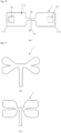
- FIG. 1 is a plan view of an energy transfer control device according to an embodiment of the present invention.
- FIG. 2 is a view illustrating a relative position of a face of a patient and the energy transfer control device when the energy transfer control device in FIG 1 is inserted into an oral cavity.
- FIG. 2 is a view illustrating a state in which a energy transfer control device 1 in FIG 1 is inserted between an outer surface of teeth and lips of the patient and between the outer surface of the teeth and an inner surface of a cheek of the patient.
- the energy transfer control device 1 may be also referred to as a shock wave transfer characteristic control tube 1 or an oral balloon 1.
- FIGS. 1 and 2 will be described with reference to FIGS. 1 and 2 .
- the energy transfer control device 1 that is a device including four fluid expansion parts 11, 12, 21, and 22, a fluid bag 13, a bridge part 19, and a fluid injection port 14 may include a synthetic resin.
- the fluid bag 13 may extend over the fluid expansion parts.
- the energy transfer control device 1 may be manufactured by stacking two thin sheets of synthetic resins (e.g., vinyl) and attaching edges thereof to each other.
- a space between non-attached surfaces in the two sheets of synthetic resins may form the fluid bag 13.
- a dotted line in FIG 1 represents an outer boundary of the fluid bag 13.
- the embodiment of the present invention is not limited thereto.
- the first fluid expansion part 11 may be inserted into a space between an inner surface of a cheek/chin skin tissue and gums of the patient, particularly into an upper right portion of the space.
- the upper right portion that is described from patient's point of view represents a upper left portion is from operator's point of view.
- the second fluid expansion part 12 may be inserted into the space between the inner surface of the cheek/chin skin tissue and the gums of the patient, particularly into a lower right portion of the space.
- the third fluid expansion part 21 may be inserted into the space between the inner surface of the cheek/chin skin tissue and the gums of the patient, particularly into an upper left portion of the space.
- the fourth fluid expansion part 22 may be inserted into the space between the inner surface of the cheek/chin skin tissue and the gums of the patient, particularly into a lower left portion of the space.
- the fluid bag 13 may have a shape connected over each of the fluid expansion parts 11, 12, 21, and 22.
- No fluid may be injected into the fluid bag 13 in a state before inserting the energy transfer control device 1 into the oral cavity.
- fluid such as air or liquid may be injected into the fluid bag 13 through the fluid injection port 14.
- fluid injection port 14 For example, a syringe 2 may be inserted into the fluid inlet 14 to inject fluid.
- the fluid expansion parts 11, 12, 21, and 22 may be expanded.
- the energy transfer control device 1 may be inserted into the oral cavity.
- the first fluid expansion part 11 may be disposed on an upper right end of a space of the oral cavity through a mouth of the patient
- the second fluid expansion part 12 may be disposed on a lower right end of the space through the mouth
- the third fluid expansion part 21 may be disposed on an upper left end of the space through the mouth
- the fourth fluid expansion part 22 may be disposed on a lower left end of the space through the mouth.
- a portion of the fluid injection port 14 may be bent to prevent the fluid from flowing out of the fluid bag 13.
- the expanded fluid expansion parts 11, 12, 21, and 22 may have a shape disposed over a facial skin area to which an ultrasonic treatment or a RF wave treatment using a separate medical device (not shown) is applied.
- the fluid may be heated by the ultrasonic energy.
- the fluid may be, e.g., air or liquid.
- the bridge part 19 is a portion to which the fluid injected through the fluid injection port 14 firstly reaches, and a portion of the fluid bag 13 is also provided in the bridge part 19.
- the bridge part 19 may provide a function of connecting the first fluid expansion part 11, the second fluid expansion part 12, the third fluid expansion part 21, and the fourth fluid expansion part 22 to each other.
- the bridge part 19 may have a significant volume, the bridge part 19 may have substantially no volume. That is, in an embodiment, the bridge part 19 may be merely a conceptual component to distinguish the first fluid expansion part 11, the second fluid expansion part 12, the third fluid expansion part 21, and the fourth fluid expansion part 22 from each other as a point at which the first fluid expansion part 11, the second fluid expansion part 12, the third fluid expansion part 21, and the fourth fluid expansion part 22 are coupled to each other.
- the bridge part 19 may have a minimum volume for defining the fluid injection port 14.
- the fluid injection port 14 may be defined at one point of the bridge part 19.
- the fluid injection port 14 may have a flexible tube shape having a predetermined length.
- An instrument for fluid injection e.g., a needle of the syringe 2
- the fluid injection port 14 may be simply bound or bent to prevent the injected fluid from flowing out again.
- the fluid injection port 14 may be formed in another portion instead of the bridge part 19, e.g., one of the first fluid expansion part 11, the second fluid expansion part 12, the third fluid expansion part 21, and the fourth fluid expansion parts 22.
- only the fluid injection port 14 may be exposed outside the lips when the patient closes the lips.
- the bridge part 19 may be disposed between an inner surface of the lips and an outer surface of front teeth of the patient.
- the above-described ultrasonic treatment is performed on the cheek/chin and surrounding facial skin instead of the lips, when a portion of the fluid bag 13 existing at the inside of the lips to which the ultrasonic wave does not reach is excessively expanded, unnecessary discomfort occurs on the lips of the patient.
- the fluid bag 13 disposed in the bridge part 19 may be designed to have a minimum volume.
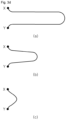
- FIGS. 3a to 3d are views for explaining an overall configuration of an energy transfer control device and a purpose of introducing a fluid bag separation gap 31 according to different embodiments.
- FIG. 3a shows, unlike FIG 1 , a shape in which the fluid expansion part inserted into the oral cavity of the right cheek/chin of the patient and the fluid expansion part inserted into the oral cavity of the left cheek/chin of the patient are integrated into one body instead of being separated into two upper and lower parts according to another embodiment of the present invention.
- FIG 3a is a plan view of a state in which fluid is injected into the fluid bag 13, and (b) of FIG 3a is a cross-sectional view taken along line C-C in (a) of FIG 3a .
- An energy transfer control device 1' may include an eleventh fluid expansion parts 111, a twelfth fluid expansion part 112, a fluid bag 113, a fluid injection port 14, and a bridge part 19.
- the fluid bag 113 may be formed in the eleventh fluid expansion part 111 and the twelfth fluid expansion part 112.
- the fluid injection port 14 may be formed to inject fluid into the fluid bag 113.
- the bridge part 19 may connect the eleventh fluid expansion part 111 to the twelfth fluid expansion part 112.
- the fluid bag 113 may have an integrated shape over the eleventh fluid expansion part 111, the twelfth fluid expansion part 112, and the bridge part 19.
- the fluid injection port 14 may be formed in the bridge part 19.
- a method for installing the energy transfer control device 1' of (a) of FIG 3 in a space between a face of the oral cavity of the patient may be performed in a following order.
- the eleventh fluid expansion part 111 may be arranged at a right side of the space through a mouth of the patient, and the twelfth fluid expansion part 112 may be arranged at a left side of the space through the mouth. Thereafter, fluid may be injected into the fluid injection port 14 to expand the fluid bag 113. Finally, a portion of the fluid injection port 14 may be bent to prevent the fluid from flowing out of the fluid bag 113.
- the method for installing the energy transfer control device 1' of (a) of FIG 3 in the space between the face of the oral cavity of the patient may be performed in a following order.
- fluid may be injected into the fluid injection port 14 to expand the fluid bag 113.
- the eleventh fluid expansion part 111 may be arranged at the right side of the space through the mouth of the patient, and the twelfth fluid expansion part 112 may be arranged at the left side of the space through the mouth.
- a portion of the fluid injection port 14 may be bent to prevent the fluid from flowing out of the fluid bag 113.
- FIG 3b shows that, as with FIG 1 , a shape in which the fluid expansion part inserted into the oral cavity of the right cheek/chin of the patient is separated into two upper and lower parts, and the fluid bag separation gap 31 inserted into the oral cavity of the left cheek/chin of the patient is separated into two upper and lower parts.
- FIG 3b is a plan view of a state in which fluid is injected into the fluid bag 13, and (b) of FIG 3b is a cross-sectional view taken along line A-A in (a) of FIG 3b .
- an energy transfer control device 1 of FIG 3b has a fluid bag separation gap 31 that is an empty space.
- the fluid bag 13 is formed without the fluid bag separation gap as illustrated in FIG 3a , the fluid bag 13 may help to prevent pain in the oral cavity of the patient.
- the effect may further increase.
- a thickness D2 of the fluid bag at the horizontal central line L1 increases in a state in which the fluid is injected.
- a portion at the horizontal central line L1 may put a pressure on a treatment area of the patient, and some patients may feel the pressure uncomfortable.
- a fluid bag separation gap 31 is disposed between a first fluid expansion part 11 and a second fluid expansion part 12.Also, the fluid bag separation gap 31 is disposed between a third fluid expansion part 21 and a fourth fluid expansion part 22.
- the fluid bag separation gap 31 represents a space between the first fluid expansion part 11 and the second fluid expansion part 12.
- the fluid bag separation gap 31 represents a membrane formed between the first fluid expansion part 11 and the second fluid expansion part 12. The membrane may be also made of the synthetic resin.
- a vertical width generated as the first fluid expansion part 11 and the second fluid expansion part 12 are separated from each other by the fluid bag separation gap 31 is expressed by W1.
- Sece fluid is not provided to the vertical width W1, ultrasonic energy may directly reach the gums and bone tissue of the patient when the ultrasonic treatment is performed on the skin on the fluid bag separation gap 31. Thus, it may be desirable to minimize the vertical width W1.
- a curved line X-Y may be defined along an edge of the fluid bag 31 formed on the first fluid expansion part 11 and the second fluid expansion part 12.
- the curved line X-Y has a concave shape from a left edge to a center of the energy transfer control device 1.
- the curved line X-Y has a structural feature provided to achieve an improved effect of the present invention described through FIGS. 3a and 3b .
- the curved line X-Y may be designed to have various curvatures and shapes, a component corresponding to the above-described fluid bag separation gap 31 is provided regardless of a shape, and the component corresponding to the fluid bag separation gap 31 exhibits an effect of preventing excessive expansion of the fluid expansion part. Thus, this may be considered to fall within the scope of the present invention.
- the additional third fluid expansion part may be provided at the left side.
- a separation gap structure corresponding to the above-described fluid bag separation gap 31 may be further provided between the third fluid expansion part and the first fluid expansion part 11 or the second fluid expansion part 12. That is, a configuration in which two or three or more fluid expansion parts that are disposed at the left or right side based on the bridge part 19 and distinguished from each other in the vertical direction is included in the concept of the present invention.
- the third fluid expansion part 21 and the fourth fluid expansion part 22 may be symmetric to the first fluid expansion part 11 and the second fluid expansion part 12, respectively.
- the separation gap 31 between the third fluid expansion part 21 and the fourth fluid expansion part 22 may have the same structure as the separation gap 31 including the above-described curved line X-Y with respect to the first fluid expansion part 11 and the second fluid expansion part 12.
- a left and right width of the bridge part 19 is not 0 (zero) in FIG 1
- the embodiment of the present invention is not limited thereto. Since the bridge part 19 that is a part in which the fluid injection port 14 is formed or connected has a substantial volume, the term is introduced to express this.
- the fluid injection port 14 is illustrated as a long pipe in FIG 1 , an embodiment in which the length of the pipe is close to zero is also included in the concept of the present invention. When the length of the pipe is 0, the fluid injection port 14 may simply exist as an opening.
- one fluid injection port 14 is formed at a central portion of the energy transfer control device 1 in FIG 1
- two or more fluid injection ports 14 may be installed at any position in which fluid is injectable into the fluid bag 13 depending on embodiments. All of these modified embodiments are included in the present invention.
- the first fluid expansion part 11, the second fluid expansion part 12, the third fluid expansion part 21, and the fourth fluid expansion part 22 may not be connected to each other by one fluid bag 13. That is, for example, empty spaces of the first fluid expansion part 11 and the second fluid expansion part 12 may be connected to each other by one first fluid bag 13_1, and empty spaces of the third fluid expansion part 21 and the fourth fluid expansion unit 22 may be connected to each other by one second fluid bag 13_2.
- the first fluid bag 13_1 and the second fluid bag 13_2 may be separated from each other.
- the fluid injection port 14 may be installed separately in the first fluid bag 13_1 and the second fluid bag 13_2.
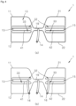
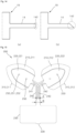
- FIG 4 is a view illustrating a structure of an energy transfer control device 1 according to a modified embodiment of the present invention.
- the energy transfer control device 1 illustrated in FIG 4 basically has the structure of the energy transfer control device 1 illustrated in FIG 1 , and an additional component is added thereto.
- FIG 4 when FIG 4 is described, a description that overlaps that in FIG 1 may be omitted.
- FIG 4 shows the additional component according to an embodiment of the present invention to solve the above-described problem.
- FIG 4 is a view illustrating a case in which a fluid injection port 14 is provided only to a bridge part 19 of an energy transfer control device 1
- (b) of FIG 4 is a view illustrating a case in which a second fluid injection port 16 is provided to each the insertion guide part 41 and the second insertion guide part 42 of an energy transfer control device 1.
- the energy transfer control device 1 may further include a first insertion guide part 41 and a second insertion guide part 42.
- Each of the first insertion guide part 41 and the second insertion guide part 42 may be additionally disposed at the position of the above-described fluid bag separation gap 31.
- the first insertion guide part 41 has one end connected to the bridge part 19 and the other end connected to the first fluid expansion part 11 and a right end of the second fluid expansion part 12 (when viewed from a patient's perspective).
- a second fluid bag separation gap 32 may be formed between the first insertion guide part 41 and the first fluid expansion part 11, and a third fluid bag separation gap 33 may be formed between the first insertion guide part 41 and the second fluid expansion part 12.
- the second fluid bag separation gap 32 may be an empty space or a thin-film connected to the first fluid expansion part 11 and the first insertion guide part 41.
- the third fluid bag separation gap 33 may be an empty space or a thin-film connected to the second fluid expansion part 12 and the first insertion guide part 41.
- Each of the second fluid bag separation gap 32 and the third fluid bag separation gap 33 may be a term that refers to a feature in which the fluid bag separation gap 31 is separated by the first insertion guide part 41.
- the second fluid bag separation gap 32 and the third fluid bag separation gap 33 may be collectively referred to as the fluid bag separation gap 31.
- a first implant 15 for easily inserting the energy transfer control device 1 into the oral cavity may be formed in the first insertion guide part 41.
- the first implant 15 may be fluid.
- the fluid may allow the first insertion guide part 41 to be tightly expanded from the inside to the outside thereof, so that the first insertion guide part 41 may maintain a shape despite of a force applied to the first insertion guide part 41.
- the fluid may be inserted in advance in a process of manufacturing the energy transfer control device 1. Alternatively, the fluid may be inserted during a procedure as described in (b) of FIG 4 .
- the first implant 15 may be, instead of the fluid, a synthetic resin having elasticity while maintaining a shape or a synthetic resin combined with metal.
- the second insertion guide part 42 also has the same configuration as the first insertion guide part 41, a detailed description thereof will be omitted.
- the first implant 15 When the first implant 15 is the fluid, the first implant 15 may be formed by the operator during a use process instead of being inserted in the process of manufacturing the energy transfer control device 1. To this end, the second fluid injection port 16 may be provided in each of the first insertion guide part 41 and the second insertion guide part 42.
- the second fluid injection port 16 is connected to the first implant 15, i.e., a space into which the fluid is injected (i.e., the first insertion guide part 41 and the second insertion guide part 42).
- the space is separated from the above-described fluid bag 13.
- the fluid may be injected firstly through the second fluid injection port 16 before the operator inserts the energy transfer control device 1 into the oral cavity of the fluid.
- the operator may push the first insertion guide part 41 into the right oral cavity of the patient and the second insertion guide part 42 into the left oral cavity of the patient to insert the energy transfer control device 1 into the oral cavity of the patient.
- the fluid expansion parts 11 and 12 in the extremely flexible state may be inserted into the first insertion guide part 41, and the fluid expansion parts 21 and 22 in the extremely flexible state may be inserted into the second insertion guide part 42.
- the operator may expand the fluid expansion parts 11, 12, 21, and 22 by injecting the fluid into the fluid bag 13 through the fluid injection port 14.
- FIG 5 is a view illustrating a structure of an energy transfer control device 1 according to another modified embodiment of the present invention.
- the energy transfer control device 1 illustrated in FIG 5 basically has the structure of the energy transfer control device 1 illustrated in FIG 1 , and an additional component is added thereto.
- FIG 4 when FIG 4 is described, a description that overlaps that in FIG 1 may be omitted.
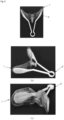
- FIG 5 (a) of FIG 5 is a view illustrating an energy transfer control device 1 in which pockets are formed in fluid expansion parts.
- the energy transfer control device 1 may include fluid expansion parts 11, 12, 21, and 22.Pockets 71, 72, 73, and 74 may be formed in the fluid expansion parts 11, 12, 21, and 22, respectively.
- the pocket has a shape similar to a pants pocket, and an insertion port of the pocket is formed toward a central portion of the energy transfer control device 1.
- FIG 5 is a view illustrating forceps having spatula parts 81, 82, 83, and 84 that are insertable into the pockets 71, 72, 73, and 74, respectively.
- the forceps 8 may include a left spatula part 91, a right spatula part 93, and a handle 92.
- the left spatula part 91 may include a first left spatula part 81 and a second left spatula part 82.
- the right spatula part 93 may include a first right spatula part 83 and a second right spatula part 84.
- the spatula parts 81, 82, 83, and 84 may be inserted into the pockets 71, 72, 73, and 74, respectively. That is, the first left spatula part 81 may be inserted into the first pocket 71, the second left spatula part 82 may be inserted into the second pocket 72, the first right spatula part 83 may be inserted into the third pocket 73, and the second right spatula part 84 may be inserted into the fourth pocket 74.
- the forceps 8 may be referred to as an insertion instrument 8.
- FIG 5 is a perspective view of the forceps 8 illustrated in (b) of FIG 5 .
- a left and right lengths VD of the handle 92 may be adjusted by a force held by a hand of the operator.
- the spatula parts 81, 82, 83, and 84 may be inserted into the pocket 71, 72, 73, and 74, respectively, before the operator inserts the energy transfer control device 1 into the oral cavity of the patient.
- the operator may insert the energy transfer control device 1 into the oral cavity of the patient by applying a force to reduce the left and right length VD of the forceps 8 coupled with the energy transfer control device 1. Thereafter, the operator allow the left and right length VD to be increased by releasing the force applied to the forceps 8 coupled with the energy transfer control device 1.
- the operator may apply a force to reduce the left and right length VD of the forceps 8 again, thereby removing the forceps 8 from the oral cavity while deforming a shape of the forceps 8.
- the operator may expand the fluid expansion parts 11, 12, 21, and 22 by injecting the fluid into the fluid bag 13 through the fluid injection port 14.
- FIGS. 6 to 9 are views illustrating products according to various ideas conceived to complete the present invention.
- FIG 6 is a front and back view illustrating a case in which the pocket is formed in the energy transfer control device and a case in which the pocket is not formed in the energy transfer control device according to an embodiment of the present invention.
- FIG 6 is a plan view of the energy transfer control device 1 in which a pocket 70 is formed
- (b) of FIG 6 is a rear view of the energy transfer control device 1 in which the pocket 70 is formed
- (c) of FIG 6 is a plan view of the energy transfer control device 1 in which the pocket is not formed
- (d) of FIG 6 is a rear view of the energy transfer control device in which the pocket is not formed.
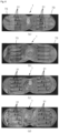
- FIG 7 is a view illustrating states before and after the energy transfer control device is expanded in each of the case in which the pocket is formed in the energy transfer control device and the case in which the pocket is not formed in the energy transfer control device according to an embodiment of the present invention.
- FIG 7 is a view illustrating a state before the energy transfer control device 1 in which the pocket 70 is formed is expanded
- (b) of FIG 7 is a view illustrating a state after the energy transfer control device 1 in which the pocket 70 is formed is expanded
- (c) of FIG 7 is a view illustrating a state before the energy transfer control device 1 in which the pocket 70 is not formed is expanded
- (d) of FIG 7 is a view illustrating a state after the energy transfer control device 1 in which the pocket 70 is not formed is expanded.
- FIG 8 is a view illustrating an appearance of the forceps according to an embodiment of the present invention.
- FIG 8 is a front view of forceps 8'
- (b) of FIG 8 is a side view of the forceps 8'
- (c) of FIG 8 is a perspective view of the forceps 8'.
- the forceps 8 may have two spatula parts.
- FIG 9 is a view illustrating states, in which the forceps are inserted into the energy transfer control device, viewed from various angles according to an embodiment of the present invention.
- a plurality of fluid bag separation gaps 31 are provided in each of the left fluid expansion part and the right fluid expansion part.
- Products that are different type of energy transfer control devices illustrated in FIGS. 6 to 9 may have an advantage and a disadvantage according to functions thereof.
- FIG 10 is a view illustrating the energy transfer control device 1' in which the pocket 70 is formed according to an embodiment of the present invention.
- the pocket 70 having in inlet formed toward a central portion of the energy transfer control device 1' may be formed in each of the eleventh fluid expansion part 111 and the twelfth fluid expansion part 112 of the energy transfer control device 1'.
- FIG 11 is a view illustrating images obtained by designing the shape the energy transfer control device 1 according to an embodiment of the present invention.
- each of the fluid expansion part and the fluid injection port of the energy transfer control device may have various shapes.
- FIG 12 is a view illustrating an energy transfer control device 1 according to an embodiment of the present invention.
- the fluid injected through the fluid injection port 14 reaches the bridge part 19. Since a portion of the fluid bag 13 is also provided to the bridge part 19, the fluid passing through the bridge part 19 is moved to the fluid expansion parts 11, 12, 21, and 22.
- FIG 13 is a cross-sectional view taken along line H-H in the energy transfer control device 1 of FIG 12 .
- FIG 13 is a view illustrating a fluid injection port 14 according to an embodiment of the present invention
- (b) of FIG 13 is a view illustrating a fluid injection port 14 according to another embodiment of the present invention.
- FIG 13 and (b) of FIG 13 are views for explaining the fluid inlet 14 formed to be easily bent when the fluid injection port 14 is bent to prevent the fluid from leaking out of the fluid injection port 14 after the fluid is injected through the fluid injection port 14.
- the fluid injection port 14 may have a tube shape having both ends.
- a cross-section may be gradually increased in a direction from a first end 141 connected to the fluid bag 13 of the bridge part 19 to a second end 142 that is not connected to the fluid bag among both ends of the fluid inlet 14.
- the first end 141 connected to the fluid bag 13 of the bridge part 19 has a narrow cross-section, the fluid injection port 14 in a direction toward the first end 141 (14) may be easily bent after the fluid is injected through the fluid injection port 14.
- the fluid injection port 14 may be divided into a first injection part 143 and a second injection part 144.
- the first injection part 143 may have one end connected to the fluid bag 13 of the bridge part 19 and the other end connected to one end of the second injection part 144.
- the fluid may be firstly injected to the other end of the second injection part 144.
- the first injection part 143 may have a diameter R1 less than a diameter R2 of the second injection part 144. That is, a stepped portion may be formed between the first injection part 143 and the second injection part 144. Due to this, since the first injection part 143 may be easily bent, the fluid may not be leaked to the fluid injection port 14 by bending a portion of the first injection part 143 after the fluid is injected through the fluid injection port 14.
- FIG 14 is a view for explaining an optimized shape of an open end of the fluid injection port 14 according to an embodiment of the present invention.
- FIG 14 shows a state in which an open end 142 of the fluid injection port 14 is cut to be parallel to the bridge part 19, and (b) of FIG 14 shows a state in which the open end 142 of the fluid injection port 14 is cut obliquely with respect to an extension direction of the fluid injection port 14.
- the fluid injection port 14 having a short length is illustrated for convenience of description in FIGS. 12 to 14
- the fluid injection port 14 may have a long length so that a passage of the fluid injection port 14 is automatically blocked by own weight of the fluid injection port 14 when the fluid injection port 14 is bent after the fluid is injected.
- FIG 15 is a front view of an oral balloon according to another embodiment of the present invention.
- An oral balloon 200 may include a first chamber 210, a second chamber 220, a third chamber 230, and a fluid passage 240.
- a term 'chamber' may be also referred to as 'room' or 'space'.
- the first chamber, second chamber, and third chamber may be referred to as the first room, the second room, and third room, respectively.
- the first chamber, second chamber, and third chamber may be referred to as the first room, the second room, and third room, respectively.
- the first chamber 210 and the second chamber 220 may be inserted into a space between teeth and an inner wall of lips (and cheeks) of a person.
- the first chamber 210 and the second chamber 220 may for one set, and the one set may be disposed at each of both cheeks of the person.
- one set including a first chamber 211 and a second chamber 221 may be disposed in a space between left teeth and an inner wall of a left cheek of the person
- another set including a first chamber 212 and a second chamber 222 may be disposed in a space between right teeth and an inner wall of a right cheek of the person.
- the second chamber 220 may be referred to as a fluid bag in this specification.
- the second chamber 221 on the left may be referred to as a eleventh fluid expansion part
- the second chamber 222 on the right may be referred to as the twelfth fluid expansion part. That is, the second chamber 220 may be formed by the eleventh fluid expansion part and the twelfth fluid expansion part.
- the first chamber 210 may be arranged to surround a portion of an edge of the second chamber 220. Here, the first chamber 210 and the second chamber 220 may be completely separated.
- the first chamber 210 may be filled with fluid.
- the fluid may be referred to as an implant in this specification.
- the implant may substantially maintain a shape when the oral balloon 200 is inserted into the oral cavity.
- the implant may include one or more of fluid, a synthetic resin, and metal.
- the fluid filled in the first chamber 210 may not be moved to the second chamber 220 because the first chamber 210 is separated from the second chamber 220.
- the second chamber 220 may not be filled with fluid.
- the oral balloon 200 may be manufactured in a state in which the first chamber 210 is filled with fluid in advance, which allows the oral balloon 200 to be easily inserted into the oral cavity.
- the first chamber 210 may be referred to as an ⁇ insertion guide part' in this specification.
- a fluid movement passage 240 for receiving fluid from the third chamber 230 may be formed in a portion of an edge of the second chamber 220, which is not surrounded by the first chamber 210.
- the first chamber 210 and the third chamber 230 may be completely separated.
- the third chamber 230 may be filled with fluid as with the first chamber 210. That is, when the oral balloon 200 is manufactured, the third chamber 230 may be manufactured in a state of being filled with fluid.
- the second chamber 220 and the third chamber 230 may be connected to each other through the fluid movement passage 240 as described above.
- first chamber 210 and the third chamber 230 may be connected only through the fluid movement passage 240 and the second chamber 220.
- the fluid movement passage 240 may include a first fluid movement passage 241 connected to the second chamber 221 on the left, a second fluid movement passage 242 connected to the second chamber 222 on the right, and a third fluid movement passage 243 connected to the third chamber 230.
- first fluid movement passage 241 and the second fluid movement passage 242 may be collectively referred to as a 'bridge part'.
- first fluid movement passage 241, the second fluid movement passage 242, and the third fluid movement passage 243 may have a 'Y' shape when viewed from the front.
- the bridge part may connect the eleventh fluid expansion part that is the second chamber 221 on the left and the twelfth fluid expansion part that is the second chamber 222 on the right.
- the first fluid movement passage 241, the second fluid movement passage 242, and the third fluid movement passage 243 of the fluid movement passage 240 may have substantially an integrated shape of connecting the second chamber 220 and the third chamber 230.
- each of the first fluid movement passage 241, the second fluid movement passage 242, and the third fluid movement passage 243, i.e., each passage may have an inner width A less than a width B of an inlet passage of each of the second chamber 220 and the third chamber 230. This represents that, when pressure is applied to the third room 230, the fluid is moved to the second chamber 220 through the fluid movement passage 240 to expand the second chamber 220, thereby preventing the fluid flowing to the second chamber 220 to be easily moved again to the third chamber 230.
- a width B of an inlet passage of the third chamber 230 based on the third chamber 230 may be a width of the entire fluid movement passage 240, and the width may be gradually increased in a direction from the inlet passage to the inner passage (i.e. B>A).
- the third fluid movement passage 243 that is substantially a common passage connected to the bridge parts 241 and 242 to inject the fluid into the second chambers 220 may be referred to as a 'fluid injection port' in this specification. That is, the fluid injection port may be formed in the bridge part.
- a first point 251 of a first surface (e.g., front surface) and a second point 252 of a second surface (e.g., rear surface) of the second chamber 220 may be bonded to each other.
- a three-dimensional shape of the second chamber 220 may be determined (restricted). This effect may be the same as that described above with reference to FIGS. 3a and 3b .
- One or more bonded areas 250 may be formed.
- the bonded area 250 may be referred to as a 'fluid bag separation gap' in this specification.
- the bonded area 250 may be obtained by bonding surfaces of the oral balloon 200 and made of the same material as the oral balloon 200.
- the area 250 may be made of a synthetic resin.
- a pocket having an inlet formed toward a central portion of the oral balloon may be formed in the second area 220.
- the pocket may have a shape similar to that of (a) of FIG 5 .
- the oral balloon 200 may include fluid injection parts 310 and 330 for injecting fluid into the oral balloon 200.
- the fluid injection parts 311 and 312 may be formed at a point on one edge of the first chambers 211 and 212 to inject the fluid into the first chambers 211 and 212.
- the fluid injection part 330 may be formed at a point on one edge of the third chamber 230 to inject the fluid into the third chamber 230.
- the fluid injection parts 311, 312, and 330 may be closed by thermal bonding after the fluid is injected during manufacturing.
- the first chamber on the left may be referred to as a left first chamber
- the first room on the right may be referred to as a right first chamber
- the second chamber on the left may be referred to as a left second chamber
- the second chamber on the right may be referred to as a right second chamber.
- the fluid movement passage 240 has a structure in which three passages meet at one point. That is, one end of the first passage, one end of the second passage, and one end of the third passage meet at one point and are connected to each other. Also, the other end of the first passage may be connected to the left second chamber, the other end of the second passage may be connected to the right second chamber, and the other end of the third passage may be connected to the third chamber.
- the first chamber 210 may have an English 'C' shape or a Korean ' ⁇ ' shape to surround an outer edge of the second chamber 220.
- a portion of the outer edge of the second chamber 220, which is not surrounded by the first chamber 210, may be connected to the fluid movement passage 240.
- a portion of the outer edge of the left second chamber, which is not surrounded by the first left chamber may be connected to the other end of the first passage.
- a portion of the outer edge of the left second chamber, which is not surrounded by the right first chamber may be connected to the other end of the second passage.
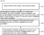
- FIG 16 is a flowchart for explaining a method for manufacturing an oral balloon according to an embodiment of the present invention.
- FIG 17 is a view illustrating a first sheet and a second sheet of the oral balloon according to an embodiment of the present invention.
- a first sheet 410 and a second sheet 420 may be arranged to overlap each other.
- the first sheet 410 and the second sheet 420 may be made of a synthetic resin.
- the first sheet 410 may be arranged on the second sheet 420 in an overlap manner.
- thermal bonding may be performed to form a first chamber 210, a second chamber 220, a third chamber 230, and a fluid movement passage 240 except for a fluid injection part 310 for injecting fluid into the first chamber 210 and the third chamber 230.
- a portion to be thermally bonded may be a portion that is colored and expressed by a thick solid line in the first sheet 410 and the second sheet 420 in FIG 17 .
- a first point 251 of the first sheet 410 of the second chamber 220 and a second point 252 of the second sheet 420 of the second chamber 220 may also be thermally bonded.
- the rest edge (colored portion) except for a first fluid movement passage 241, a second fluid movement passage 242, and a third fluid movement passage 243 among the fluid movement passages 240 may be widely thermally bonded.
- only a portion expressed by two dotted lines in the first fluid movement passage 241, the second fluid movement passage 242, and the third fluid movement passage 243 among the fluid movement passages 240 of FIG 15 may be thermally bonded.
- fluid may be injected through fluid injection parts 311, 312, and 330 formed in the first chamber 210 and the third chamber 230.
- the fluid injection parts 311, 312, and 330 are expressed by a thin solid line. That is, it may be known that the fluid injection parts 310 and 330 are not thermally bonded until the fluid is injected.
- step S40 the fluid injection part 310 of the first chamber 210 and the fluid injection part 330 of the third chamber 230 may be thermally bonded to be blocked.
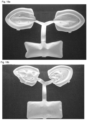
- a state in which the thermal bonding of the oral balloon is completed may be as shown in FIG 18a .
- FIG 18a is a front view of the oral balloon in a state in which the second chamber is not filled with fluid according to an embodiment of the present invention
- FIG 18b is a front view of the oral balloon in a state in which the second chamber is filled with the fluid according to an embodiment of the present invention.
- FIG 18a may be a view of the oral balloon immediately after being manufactured according to the above-described steps in FIG 16 . Accordingly, the fluid injection part 310 of the first chamber 210 and the fluid injection part 330 of the third chamber 230 may be blocked through the thermal bonding.
- fluid in the third chamber 230 may be supplied to the second chamber 220 through the fluid movement passage 240, so that the second chamber 220 is expanded.
- the expanded second chamber 220 may have an appearance as shown in FIG 18b .
- a degree of expansion of the third chamber 230 may be reduced.
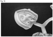
- FIG 19 is a front view illustrating the first and second chambers of the oral balloon in the state in which the second chamber filled with the fluid according to an embodiment of the present invention.
- the second chamber 220 may be in an expanded state, and, for example, four bonded areas may be formed in the second chamber 220. As the above-described bonded area is formed, the effects described in FIGS. 3a and 3a may be obtained.
- the second chamber 220 may have one bonded area or a plurality of bonded areas.
- a set of the first chamber 210 and the second chamber 220 may be arranged in a mouth of the patient.
- one set of the first and second chambers may be arranged at a left side in the mouth of the patient, and another set may be arranged at a right side in the mouth of the patient.
- pressure may be applied to the third chamber 230 to inject the fluid through the fluid movement passage 240 (i.e., fluid injection port and bridge part), thereby expanding the second chamber 220.
- pressure may be applied to the third chamber 230 to inject the fluid through the fluid movement passage 240 (i.e., fluid injection port and bridge part), thereby expanding the second chamber 220.
- the set of the first chamber 210 and the second chamber 220 may be arranged in the mouth of the patient.
- one set of the first and second chambers may be arranged at the left side in the mouth of the patient, and another set may be arranged at the right side in the mouth of the patient.
Landscapes
- Health & Medical Sciences (AREA)
- Life Sciences & Earth Sciences (AREA)
- General Health & Medical Sciences (AREA)
- Animal Behavior & Ethology (AREA)
- Surgery (AREA)
- Oral & Maxillofacial Surgery (AREA)
- Veterinary Medicine (AREA)
- Public Health (AREA)
- Biomedical Technology (AREA)
- Medical Informatics (AREA)
- Molecular Biology (AREA)
- Heart & Thoracic Surgery (AREA)
- Nuclear Medicine, Radiotherapy & Molecular Imaging (AREA)
- Pathology (AREA)
- Engineering & Computer Science (AREA)
- Dentistry (AREA)
- Epidemiology (AREA)
- Prostheses (AREA)
- Percussion Or Vibration Massage (AREA)
Applications Claiming Priority (4)
| Application Number | Priority Date | Filing Date | Title |
|---|---|---|---|
| KR20210052574 | 2021-04-22 | ||
| KR20210066256 | 2021-05-24 | ||
| KR1020210142866A KR102667743B1 (ko) | 2021-04-22 | 2021-10-25 | 에너지 전달특성을 제어하는 구강 삽입용 장치 |
| PCT/KR2022/003114 WO2022225176A1 (ko) | 2021-04-22 | 2022-03-04 | 에너지 전달특성을 제어하는 구강 삽입용 장치 |
Publications (2)
| Publication Number | Publication Date |
|---|---|
| EP4327770A1 true EP4327770A1 (de) | 2024-02-28 |
| EP4327770A4 EP4327770A4 (de) | 2025-04-23 |
Family
ID=83722908
Family Applications (1)
| Application Number | Title | Priority Date | Filing Date |
|---|---|---|---|
| EP22791876.0A Pending EP4327770A4 (de) | 2021-04-22 | 2022-03-04 | Vorrichtung zur oralen einsetzung zur steuerung von energieübertragungseigenschaften |
Country Status (3)
| Country | Link |
|---|---|
| EP (1) | EP4327770A4 (de) |
| JP (1) | JP7621013B2 (de) |
| WO (1) | WO2022225176A1 (de) |
Family Cites Families (7)
| Publication number | Priority date | Publication date | Assignee | Title |
|---|---|---|---|---|
| JPH0420430Y2 (de) * | 1989-08-24 | 1992-05-11 | ||
| KR101401133B1 (ko) | 2012-11-28 | 2014-06-17 | (주)아마오리엔트 | 초음파 및 고주파를 이용한 피부치료기 및 그 제어방법 |
| KR101822859B1 (ko) * | 2017-02-03 | 2018-01-30 | 경희대학교 산학협력단 | 자극량 조절이 가능한 혀 자극치료기 |
| US11357664B2 (en) * | 2017-02-17 | 2022-06-14 | Chemomouthpiece, Llc | Hand-held mouthpiece for cooling of oral tissue of a user |
| KR102096781B1 (ko) * | 2018-07-19 | 2020-04-03 | 나공찬 | 구강 내 구비가능한 충격파 전달 방지 튜브 |
| KR102373582B1 (ko) * | 2020-01-17 | 2022-03-11 | 나공찬 | 충격파 전달특성을 제어하는 구강 삽입용 장치 |
| CN212973892U (zh) * | 2020-04-16 | 2021-04-16 | 桂林医学院附属医院 | 一种大小可调节的医用张口器 |
-
2022
- 2022-03-04 WO PCT/KR2022/003114 patent/WO2022225176A1/ko not_active Ceased
- 2022-03-04 JP JP2023565449A patent/JP7621013B2/ja active Active
- 2022-03-04 EP EP22791876.0A patent/EP4327770A4/de active Pending
Also Published As
| Publication number | Publication date |
|---|---|
| JP7621013B2 (ja) | 2025-01-24 |
| WO2022225176A1 (ko) | 2022-10-27 |
| JP2024517684A (ja) | 2024-04-23 |
| EP4327770A4 (de) | 2025-04-23 |
Similar Documents
| Publication | Publication Date | Title |
|---|---|---|
| US20250025212A1 (en) | Device and method for artificial insemination | |
| CN102946924B (zh) | 用于将插入构件插入患者的身体组织的装置 | |
| JP4288165B2 (ja) | 腹膜透析カテーテル | |
| TW200821002A (en) | Indwelling catheter, hollow needle, and indwelling needle assembly | |
| CN105611956B (zh) | 颅骨植入型药物注射端口 | |
| AU2019233923B2 (en) | Systems and methods for treating the nasal cavity | |
| US20150051683A1 (en) | Malleable implantable medical device | |
| JP2001502956A (ja) | 密な穿刺シール | |
| EP4327770A1 (de) | Vorrichtung zur oralen einsetzung zur steuerung von energieübertragungseigenschaften | |
| KR102189608B1 (ko) | 부비강 접근 임플란트 디바이스들 및 관련 툴들, 방법들 및 키트들 | |
| WO2019108818A1 (en) | Device and method for artificial insemination | |
| KR102373582B1 (ko) | 충격파 전달특성을 제어하는 구강 삽입용 장치 | |
| KR102667743B1 (ko) | 에너지 전달특성을 제어하는 구강 삽입용 장치 | |
| US20240277528A1 (en) | Advanced ear access | |
| KR20150030499A (ko) | 복수의 실을 삽입하는 매선장치 | |
| JP7660936B2 (ja) | 最小限に侵襲的な埋め込みのための皮下ポート | |
| CN117915854A (zh) | 控制能量传递特性的口腔插入用装置 | |
| KR101399346B1 (ko) | 생체적합성 유방 성형 보형물 주입장치 | |
| KR20210042304A (ko) | 고막 주사용 팁 | |
| EP4473920A1 (de) | Hämostasevorrichtung | |
| KR102241531B1 (ko) | 고막 주사용 팁 | |
| TW202513112A (zh) | 人工耳蝸內投予裝置 |
Legal Events
| Date | Code | Title | Description |
|---|---|---|---|
| STAA | Information on the status of an ep patent application or granted ep patent |
Free format text: STATUS: THE INTERNATIONAL PUBLICATION HAS BEEN MADE |
|
| PUAI | Public reference made under article 153(3) epc to a published international application that has entered the european phase |
Free format text: ORIGINAL CODE: 0009012 |
|
| STAA | Information on the status of an ep patent application or granted ep patent |
Free format text: STATUS: REQUEST FOR EXAMINATION WAS MADE |
|
| 17P | Request for examination filed |
Effective date: 20231122 |
|
| AK | Designated contracting states |
Kind code of ref document: A1 Designated state(s): AL AT BE BG CH CY CZ DE DK EE ES FI FR GB GR HR HU IE IS IT LI LT LU LV MC MK MT NL NO PL PT RO RS SE SI SK SM TR |
|
| DAV | Request for validation of the european patent (deleted) | ||
| DAX | Request for extension of the european patent (deleted) | ||
| A4 | Supplementary search report drawn up and despatched |
Effective date: 20250321 |
|
| RIC1 | Information provided on ipc code assigned before grant |
Ipc: A61B 18/00 20060101ALI20250317BHEP Ipc: A61N 1/04 20060101ALI20250317BHEP Ipc: A61N 1/30 20060101ALI20250317BHEP Ipc: A61N 7/00 20060101ALI20250317BHEP Ipc: A61C 5/90 20170101ALI20250317BHEP Ipc: A61B 90/00 20160101AFI20250317BHEP |