EP4324990A1 - Rosette murale dotée d'une rosette murale rectangulaire pour une armature sanitaire en saillie - Google Patents
Rosette murale dotée d'une rosette murale rectangulaire pour une armature sanitaire en saillie Download PDFInfo
- Publication number
- EP4324990A1 EP4324990A1 EP23191860.8A EP23191860A EP4324990A1 EP 4324990 A1 EP4324990 A1 EP 4324990A1 EP 23191860 A EP23191860 A EP 23191860A EP 4324990 A1 EP4324990 A1 EP 4324990A1
- Authority
- EP
- European Patent Office
- Prior art keywords
- wall
- fastening element
- rosette
- wall rosette
- shoulder
- Prior art date
- Legal status (The legal status is an assumption and is not a legal conclusion. Google has not performed a legal analysis and makes no representation as to the accuracy of the status listed.)
- Pending
Links
- 239000011505 plaster Substances 0.000 title 1
- 238000007789 sealing Methods 0.000 claims abstract description 15
- 230000005540 biological transmission Effects 0.000 claims abstract description 4
- 239000012815 thermoplastic material Substances 0.000 claims description 2
- 230000007704 transition Effects 0.000 claims description 2
- 230000006835 compression Effects 0.000 description 3
- 238000007906 compression Methods 0.000 description 3
- 230000000694 effects Effects 0.000 description 3
- XLYOFNOQVPJJNP-UHFFFAOYSA-N water Substances O XLYOFNOQVPJJNP-UHFFFAOYSA-N 0.000 description 3
- 238000004026 adhesive bonding Methods 0.000 description 1
- 238000004140 cleaning Methods 0.000 description 1
- 229920001971 elastomer Polymers 0.000 description 1
- 239000000806 elastomer Substances 0.000 description 1
- 238000009434 installation Methods 0.000 description 1
- 230000000007 visual effect Effects 0.000 description 1
Images


Classifications
-
- E—FIXED CONSTRUCTIONS
- E03—WATER SUPPLY; SEWERAGE
- E03C—DOMESTIC PLUMBING INSTALLATIONS FOR FRESH WATER OR WASTE WATER; SINKS
- E03C1/00—Domestic plumbing installations for fresh water or waste water; Sinks
- E03C1/02—Plumbing installations for fresh water
- E03C1/04—Water-basin installations specially adapted to wash-basins or baths
- E03C1/042—Arrangements on taps for wash-basins or baths for connecting to the wall
-
- E—FIXED CONSTRUCTIONS
- E03—WATER SUPPLY; SEWERAGE
- E03C—DOMESTIC PLUMBING INSTALLATIONS FOR FRESH WATER OR WASTE WATER; SINKS
- E03C1/00—Domestic plumbing installations for fresh water or waste water; Sinks
- E03C1/02—Plumbing installations for fresh water
- E03C1/021—Devices for positioning or connecting of water supply lines
-
- E—FIXED CONSTRUCTIONS
- E03—WATER SUPPLY; SEWERAGE
- E03C—DOMESTIC PLUMBING INSTALLATIONS FOR FRESH WATER OR WASTE WATER; SINKS
- E03C1/00—Domestic plumbing installations for fresh water or waste water; Sinks
- E03C1/02—Plumbing installations for fresh water
- E03C2001/026—Plumbing installations for fresh water with flow restricting devices
-
- E—FIXED CONSTRUCTIONS
- E03—WATER SUPPLY; SEWERAGE
- E03C—DOMESTIC PLUMBING INSTALLATIONS FOR FRESH WATER OR WASTE WATER; SINKS
- E03C2201/00—Details, devices or methods not otherwise provided for
- E03C2201/50—Constructional features of escutcheons for domestic plumbing installations
Definitions
- the invention relates to a wall rosette arrangement with a rectangular wall rosette for an exposed sanitary fitting with the features of the preamble of claim 1.
- S-bends are usually inserted into the socket ends of the hot and cold water pipes at a water tap point prepared on the building side. These are water-conducting parts that have threads on both sides. The two thread shoulders are parallel and offset from one another. By turning the two S-bends, slight deviations in the pitch between the two sleeve ends from the target dimension can be compensated for. Small misalignments can also be corrected during fine assembly so that the fitting is aligned exactly horizontally.
- wall rosettes are placed on the threaded shoulders of the S-bows that emerge from the wall. For round wall rosettes, it is sufficient to push them onto the threaded shoulder.
- the existing thread can also be used to screw the wall rosette onto the threaded shoulder and clamp it against the wall surface.
- a wall rosette arrangement for a round wall rosette is known.
- This includes a fastening element that can be screwed onto an S-bend and that has a pressure washer, on the back of which a sealing ring is held for sealing against the wall surface.
- the actual rosette which serves as a decorative and covering element, is shaped like a cone and can be snapped onto the fastening element. Neither an angular position is specified in a positive or frictional manner, nor is an angular position once manually set maintained, so that it is not suitable for angular wall rosettes.
- the object of the present invention is to improve a square wall rosette for a surface-mounted sanitary fitting so that it can be precisely aligned during installation and that the wall rosettes cannot be accidentally twisted even during later use, for example when cleaning.
- the invention is based on the fact that a fastening element is inserted between the S-bend and the wall rosette, in which at least one annular shoulder is present or which itself is annular overall.
- the shoulder provided for connection has an internal thread through which it can be screwed onto the threaded shoulder of the S-bend, in particular to such an extent that wall contact is established and axial bracing between the wall and S-bend is achieved. As a result, the fastening element is secured against rotation.
- the security of the fastening element against rotation can also be achieved by making the thread undersized or e.g. B. by gluing the fastener to the threaded shoulder.
- At least one clamping means is provided on the fastening element and/or on the wall rosette, via which the wall rosette can be clamped onto the fastening element by axial thrust in the direction of the wall surface, i.e. without a screw thread or additional fastening means, and is held in the position reached so that it cannot rotate.
- the clamping means is an O-ring that is made of an elastomer.
- the associated wall rosette has a rectangular front panel and a surrounding frame, so that a cuboid-shaped hollow body that is open on one side is formed.
- the front panel has an opening for an S-bend on the building side.
- the front panel is adjoined by a particularly cup-shaped receptacle, which can be clamped onto the associated shoulder on the fastening element with the clamping means, in particular an O-ring or another elastomeric element.
- the cup-shaped receptacle has an inner diameter that is coordinated with respect to the outer diameter of the O-ring or another elastomeric element so that compression is possible with forces that can be caused by manually pushing the wall rosette axially onto the fastening element.
- the compression causes a frictional clamping and the angular position, once set, is maintained when the sanitary fitting is in use and can only be changed with great effort, so that unintentional or even automatic twisting of the wall rosette is ruled out.
- At least one form-fitting means is provided on the outer circumference of the fastening element. This can be at least one pair of wrench surfaces on which an open-end wrench can be attached.
- the internal thread on the fastening element which is made in particular from thermoplastic material, with a slight undersize in the form of a transition fit, so that the clamping forces are increased and a later unintentional rotation on the thread shoulder of the S-bend is prevented is avoided.
- An additional shoulder on the fastening element forms a pressure washer with a larger diameter, which is placed against the wall when the fastening element is screwed onto the S-bend.
- the pressure disk has at least one sealing ring on its back facing the wall.
- the fastening element also has an annular shoulder which is intended for connection to the S-bend.
- the same shoulder or another shoulder can accommodate the O-ring, onto which a cup-shaped receptacle, which is formed on the back of the front surface of the wall rosette around the through opening, can be clamped.
- the outer circumference of the shoulder provided for fastening on the fastening element is cylindrical, just as the inner circumference of the receptacle is cylindrical. This means that the clamping effect is determined solely by matching the inner diameter of the mount on the wall rosette and the outer diameter of the O-ring.
- the outer circumference of the fastening element can also be conical, with the cup-shaped receptacle on the wall rosette being cylindrical or vice versa.
- the cone angle should be less than 5°, rather less than 2°.
- the design with a cone has the advantage that the strength of the compression of the O-ring and the clamping force when pushing on the wall rosette can be adjusted. Since the inner diameter of the receptacle tapers conically towards the back of the front panel, the annular gap between the shoulder and receptacle also tapers and the O-ring located there is compressed more strongly the further the rosette is moved axially on the fastening element. To adjust the clamping force, the fastening element on the threaded shoulder of the S-bend can be positioned axially closer to the wall or slightly further away from it.
- the clamping means is formed by at least one resilient pin, which is connected to the rear side of the front panel of the wall rosette and which can be snapped into a recess on the shoulder of the fastening element with a locking projection. In the axial direction, the locking projection creates a positive lock.
- the anti-twist device is also frictional, as the resilient pin presses on the heel.
- the clamping effect is preferably increased in that the recess is a groove extending over the outer circumference and that around the There are several resilient pins around the opening of the wall rosette, which engage in the groove.
- the resilient pins can be part of the cup-shaped receptacle on the back of the wall rosette, or they can form a circular arrangement that replaces such a receptacle.
- the frictional connection can be further increased by the fact that an elastomeric sealing ring is mounted on the shoulder of the fastening element, as in the first embodiment, and that the pins spring onto the sealing ring or engage over the sealing ring into the recess and at the same time contact the sealing ring. It is also conceivable to mount the additional sealing ring directly in the groove.
- a plurality of positioning notches are formed on the outer circumference of the shoulder that has the largest diameter, i.e. usually on the outer circumference of the pressure disk, which are arranged at a small angular pitch to one another .
- These positioning notches can also form a corrugated structure as a form-fitting means for torque transmission.
- at least one pin or web is formed or otherwise attached to the inside of the frame of the wall rosette, which engages in one of several positioning notches when the wall rosette is pushed axially onto the fastening element.
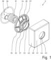
- FIG 3 a wall rosette arrangement 2 according to the invention is shown in an exploded view.
- An S-arch 30 is present on the building side. It has two threaded shoulders 31, one of which protrudes from the wall level.
- a fastening element 20 has an annular shoulder 21 with a threaded hole 23 with which it can be screwed onto the threaded shoulder 31 of the S-bend 30. Key surfaces 22 are formed on the shoulder 21 and an O-ring 27 is fitted.
- a receptacle for another sealing ring 26 is formed on the back of the pressure disk 24.
- Figure 2 shows the back of the wall rosette 40 in a perspective view. It has a front panel 41 with a through opening 43 and is surrounded by a frame 42, so that a cuboid, open at the back Hollow body is formed.
- a cup-shaped receptacle 44 adjoins the feed-through opening 43 on the back of the front plate 42, the inner diameter of which is larger than the diameter of the feed-through opening 43, since the radial area in between is required to accommodate the fastening element 20 including the O-ring.
- FIG 3 a fastening element 20' is shown for a second embodiment of a wall rosette arrangement 3 designed according to the invention.
- the fastening element 20' has been screwed onto a threaded shoulder 31, which protrudes from a wall plane, until it rests on the wall surface.
- the fastening element 20 ' has an annular shoulder 21' with which it can be screwed onto the threaded shoulder 31 of the S-bend 30.
- a circumferential recess in the form of a groove 27' with a trapezoidal cross-section is provided on the shoulder 21', and two parallel key surfaces 22' are formed on the shoulder 21'.
- the shoulder 21' is adjoined by an annular pressure disk 24', which has a larger diameter than the shoulder 21' and is supported on it via webs 25'.
- a tooth structure with a plurality of positioning notches 28' is formed on the outer circumference of the pressure disk 24'.
- a corresponding wall rosette 40 is in Fig. 4 shown in perspective view. It has a front panel 41' with a through opening 43'. The front panel 41' is surrounded by a frame 42', so that a cuboid hollow body that is open at the rear is formed. Several locking pins 44' are connected to the back of the front surface 41' of the wall rosette 40', so that the locking pins 44' protrude into the cavity and form a receiving ring 45'. In addition, webs 46' are formed at four positions on the inside of the frame 42'.
- FIG. 5 shows the entire wall rosette arrangement 3 from the back.
- the wall rosette 40' is attached to the fastening element 20' in that the front panel 41 'has a plurality of resilient locking pins 44' on its rear side, which protrude vertically and which can each be snapped into the groove 27' on the shoulder 21' with a locking pin 44'.
- the webs 46' each engage in one of the numerous positioning notches 28' which are formed on the outer circumference of the annular pressure disk 24' of the fastening element 20'.
- a receptacle for another sealing ring 26' is formed on the back of the pressure disk 24'.
- Figure 6 shows the entire wall rosette arrangement 3 in a perspective sectional view, in particular the engagement of the locking pins 44 'in the groove 27' being visible.
Applications Claiming Priority (1)
| Application Number | Priority Date | Filing Date | Title |
|---|---|---|---|
| DE202022121077 | 2022-08-19 |
Publications (1)
| Publication Number | Publication Date |
|---|---|
| EP4324990A1 true EP4324990A1 (fr) | 2024-02-21 |
Family
ID=87695863
Family Applications (1)
| Application Number | Title | Priority Date | Filing Date |
|---|---|---|---|
| EP23191860.8A Pending EP4324990A1 (fr) | 2022-08-19 | 2023-08-17 | Rosette murale dotée d'une rosette murale rectangulaire pour une armature sanitaire en saillie |
Country Status (1)
| Country | Link |
|---|---|
| EP (1) | EP4324990A1 (fr) |
Citations (10)
| Publication number | Priority date | Publication date | Assignee | Title |
|---|---|---|---|---|
| US3615108A (en) * | 1969-03-24 | 1971-10-26 | Sajar Plastics Inc | Escutcheon plate |
| US5447338A (en) * | 1993-04-23 | 1995-09-05 | Senju Sprinkler Company Limited | Escutcheon for use with sprinkler head |
| DE102005007778A1 (de) | 2005-02-19 | 2006-08-24 | American Standard Europe B.V.B.A. | Einrichtung zum Abdecken eines Wandanschlusses für eine Sanitärarmatur |
| US20080211226A1 (en) * | 2007-03-01 | 2008-09-04 | Accor Technology, Inc. | Enhanced escutcheon cover plate |
| CN103290889B (zh) * | 2012-10-19 | 2015-05-20 | 宁波敏宝卫浴五金水暖洁具有限公司 | 一种方墙罩固定方法及固定结构 |
| DE102014010130A1 (de) * | 2014-07-09 | 2016-01-14 | Grohe Ag | Abdeckvorrichtung für ein Anschlussstück einer Wasserarmatur |
| DE102015000743A1 (de) * | 2015-01-19 | 2016-07-21 | Ritterwand Gmbh & Co. Kg Metall-Systembau | Rosette |
| EP3124709A1 (fr) * | 2015-07-30 | 2017-02-01 | Ideal Standard International NV | Dispositif de rosace |
| EP3162970A1 (fr) * | 2015-10-28 | 2017-05-03 | Oras Oy | Rondelle de couverture pour appareil sanitaire encastré |
| US20220098848A1 (en) * | 2020-09-29 | 2022-03-31 | Brent Waterman | Pipe covering |
-
2023
- 2023-08-17 EP EP23191860.8A patent/EP4324990A1/fr active Pending
Patent Citations (10)
| Publication number | Priority date | Publication date | Assignee | Title |
|---|---|---|---|---|
| US3615108A (en) * | 1969-03-24 | 1971-10-26 | Sajar Plastics Inc | Escutcheon plate |
| US5447338A (en) * | 1993-04-23 | 1995-09-05 | Senju Sprinkler Company Limited | Escutcheon for use with sprinkler head |
| DE102005007778A1 (de) | 2005-02-19 | 2006-08-24 | American Standard Europe B.V.B.A. | Einrichtung zum Abdecken eines Wandanschlusses für eine Sanitärarmatur |
| US20080211226A1 (en) * | 2007-03-01 | 2008-09-04 | Accor Technology, Inc. | Enhanced escutcheon cover plate |
| CN103290889B (zh) * | 2012-10-19 | 2015-05-20 | 宁波敏宝卫浴五金水暖洁具有限公司 | 一种方墙罩固定方法及固定结构 |
| DE102014010130A1 (de) * | 2014-07-09 | 2016-01-14 | Grohe Ag | Abdeckvorrichtung für ein Anschlussstück einer Wasserarmatur |
| DE102015000743A1 (de) * | 2015-01-19 | 2016-07-21 | Ritterwand Gmbh & Co. Kg Metall-Systembau | Rosette |
| EP3124709A1 (fr) * | 2015-07-30 | 2017-02-01 | Ideal Standard International NV | Dispositif de rosace |
| EP3162970A1 (fr) * | 2015-10-28 | 2017-05-03 | Oras Oy | Rondelle de couverture pour appareil sanitaire encastré |
| US20220098848A1 (en) * | 2020-09-29 | 2022-03-31 | Brent Waterman | Pipe covering |
Similar Documents
| Publication | Publication Date | Title |
|---|---|---|
| EP2225811B1 (fr) | Raccord | |
| DE19637074A1 (de) | Kupplungseinrichtung zur Verbindung zweier Rohrelemente | |
| LU84418A1 (de) | Kupplungselement | |
| DE202006018110U1 (de) | Steckverbinder für Vorderwandmontage oder Hinterwandmontage | |
| EP1450052B1 (fr) | Elément de ferrure | |
| EP0632872B1 (fr) | Accouplement de securite emmanchable pour conduites sous pression | |
| DE102004007745B3 (de) | Steckfitting mit einem Klemmring | |
| DE69927031T2 (de) | Rohrkupplung | |
| EP0327494A1 (fr) | Raccord de sécurité à fiche, notamment pour conduites à air sous pression | |
| EP0964493A2 (fr) | Entrée de câble de forme angulaire avec une lieu de séparation entre les deux branches | |
| EP1321589B1 (fr) | Ferrure de fixation pour fixation sanitaire | |
| EP2918354B1 (fr) | Presse destinée à comprimer axialement des pièces à usiner | |
| EP4324990A1 (fr) | Rosette murale dotée d'une rosette murale rectangulaire pour une armature sanitaire en saillie | |
| DE19628780B4 (de) | Anordnung zur Schnellbefestigung einer Sanitärarmatur | |
| DE102022121077A1 (de) | Wandrosettenanordnung mit einer rechteckigen Wandrosette für eine Aufputz-Sanitärarmatur | |
| DE102007059329A1 (de) | Steckverbindung für Rohrleitungen | |
| DE19715293B4 (de) | Steckverbindung für Rohrleitungen | |
| DE4110809A1 (de) | Moebelverbindungsbeschlag | |
| DE4102048C2 (de) | Sanitärarmatur | |
| DE4420470C2 (de) | Kupplung, insbesondere für Sanitär- und Versorgungseinrichtungen und -leitungen oder dergleichen | |
| DE60017342T2 (de) | Befestigungsvorrichtung für Profile | |
| DE10357646B4 (de) | Wanddurchführung | |
| DE10236183B4 (de) | Rohrleuchte mit Verschlussvorrichtung für Rohrelemente | |
| DE2412679A1 (de) | Wandanschluss fuer wasserarmatur | |
| DE4443545B4 (de) | Steckverbinder |
Legal Events
| Date | Code | Title | Description |
|---|---|---|---|
| PUAI | Public reference made under article 153(3) epc to a published international application that has entered the european phase |
Free format text: ORIGINAL CODE: 0009012 |
|
| STAA | Information on the status of an ep patent application or granted ep patent |
Free format text: STATUS: THE APPLICATION HAS BEEN PUBLISHED |
|
| AK | Designated contracting states |
Kind code of ref document: A1 Designated state(s): AL AT BE BG CH CY CZ DE DK EE ES FI FR GB GR HR HU IE IS IT LI LT LU LV MC ME MK MT NL NO PL PT RO RS SE SI SK SM TR |