EP4324990A1 - Wall rosette assembly with rectangular wall rosette for a plaster sanitary fitting - Google Patents
Wall rosette assembly with rectangular wall rosette for a plaster sanitary fitting Download PDFInfo
- Publication number
- EP4324990A1 EP4324990A1 EP23191860.8A EP23191860A EP4324990A1 EP 4324990 A1 EP4324990 A1 EP 4324990A1 EP 23191860 A EP23191860 A EP 23191860A EP 4324990 A1 EP4324990 A1 EP 4324990A1
- Authority
- EP
- European Patent Office
- Prior art keywords
- wall
- fastening element
- rosette
- wall rosette
- shoulder
- Prior art date
- Legal status (The legal status is an assumption and is not a legal conclusion. Google has not performed a legal analysis and makes no representation as to the accuracy of the status listed.)
- Pending
Links
- 239000011505 plaster Substances 0.000 title 1
- 238000007789 sealing Methods 0.000 claims abstract description 15
- 230000005540 biological transmission Effects 0.000 claims abstract description 4
- 239000012815 thermoplastic material Substances 0.000 claims description 2
- 230000007704 transition Effects 0.000 claims description 2
- 230000006835 compression Effects 0.000 description 3
- 238000007906 compression Methods 0.000 description 3
- 230000000694 effects Effects 0.000 description 3
- XLYOFNOQVPJJNP-UHFFFAOYSA-N water Substances O XLYOFNOQVPJJNP-UHFFFAOYSA-N 0.000 description 3
- 238000004026 adhesive bonding Methods 0.000 description 1
- 238000004140 cleaning Methods 0.000 description 1
- 229920001971 elastomer Polymers 0.000 description 1
- 239000000806 elastomer Substances 0.000 description 1
- 238000009434 installation Methods 0.000 description 1
- 230000000007 visual effect Effects 0.000 description 1
Images


Classifications
-
- E—FIXED CONSTRUCTIONS
- E03—WATER SUPPLY; SEWERAGE
- E03C—DOMESTIC PLUMBING INSTALLATIONS FOR FRESH WATER OR WASTE WATER; SINKS
- E03C1/00—Domestic plumbing installations for fresh water or waste water; Sinks
- E03C1/02—Plumbing installations for fresh water
- E03C1/04—Water-basin installations specially adapted to wash-basins or baths
- E03C1/042—Arrangements on taps for wash-basins or baths for connecting to the wall
-
- E—FIXED CONSTRUCTIONS
- E03—WATER SUPPLY; SEWERAGE
- E03C—DOMESTIC PLUMBING INSTALLATIONS FOR FRESH WATER OR WASTE WATER; SINKS
- E03C1/00—Domestic plumbing installations for fresh water or waste water; Sinks
- E03C1/02—Plumbing installations for fresh water
- E03C1/021—Devices for positioning or connecting of water supply lines
-
- E—FIXED CONSTRUCTIONS
- E03—WATER SUPPLY; SEWERAGE
- E03C—DOMESTIC PLUMBING INSTALLATIONS FOR FRESH WATER OR WASTE WATER; SINKS
- E03C1/00—Domestic plumbing installations for fresh water or waste water; Sinks
- E03C1/02—Plumbing installations for fresh water
- E03C2001/026—Plumbing installations for fresh water with flow restricting devices
-
- E—FIXED CONSTRUCTIONS
- E03—WATER SUPPLY; SEWERAGE
- E03C—DOMESTIC PLUMBING INSTALLATIONS FOR FRESH WATER OR WASTE WATER; SINKS
- E03C2201/00—Details, devices or methods not otherwise provided for
- E03C2201/50—Constructional features of escutcheons for domestic plumbing installations
Definitions
- the invention relates to a wall rosette arrangement with a rectangular wall rosette for an exposed sanitary fitting with the features of the preamble of claim 1.
- S-bends are usually inserted into the socket ends of the hot and cold water pipes at a water tap point prepared on the building side. These are water-conducting parts that have threads on both sides. The two thread shoulders are parallel and offset from one another. By turning the two S-bends, slight deviations in the pitch between the two sleeve ends from the target dimension can be compensated for. Small misalignments can also be corrected during fine assembly so that the fitting is aligned exactly horizontally.
- wall rosettes are placed on the threaded shoulders of the S-bows that emerge from the wall. For round wall rosettes, it is sufficient to push them onto the threaded shoulder.
- the existing thread can also be used to screw the wall rosette onto the threaded shoulder and clamp it against the wall surface.
- a wall rosette arrangement for a round wall rosette is known.
- This includes a fastening element that can be screwed onto an S-bend and that has a pressure washer, on the back of which a sealing ring is held for sealing against the wall surface.
- the actual rosette which serves as a decorative and covering element, is shaped like a cone and can be snapped onto the fastening element. Neither an angular position is specified in a positive or frictional manner, nor is an angular position once manually set maintained, so that it is not suitable for angular wall rosettes.
- the object of the present invention is to improve a square wall rosette for a surface-mounted sanitary fitting so that it can be precisely aligned during installation and that the wall rosettes cannot be accidentally twisted even during later use, for example when cleaning.
- the invention is based on the fact that a fastening element is inserted between the S-bend and the wall rosette, in which at least one annular shoulder is present or which itself is annular overall.
- the shoulder provided for connection has an internal thread through which it can be screwed onto the threaded shoulder of the S-bend, in particular to such an extent that wall contact is established and axial bracing between the wall and S-bend is achieved. As a result, the fastening element is secured against rotation.
- the security of the fastening element against rotation can also be achieved by making the thread undersized or e.g. B. by gluing the fastener to the threaded shoulder.
- At least one clamping means is provided on the fastening element and/or on the wall rosette, via which the wall rosette can be clamped onto the fastening element by axial thrust in the direction of the wall surface, i.e. without a screw thread or additional fastening means, and is held in the position reached so that it cannot rotate.
- the clamping means is an O-ring that is made of an elastomer.
- the associated wall rosette has a rectangular front panel and a surrounding frame, so that a cuboid-shaped hollow body that is open on one side is formed.
- the front panel has an opening for an S-bend on the building side.
- the front panel is adjoined by a particularly cup-shaped receptacle, which can be clamped onto the associated shoulder on the fastening element with the clamping means, in particular an O-ring or another elastomeric element.
- the cup-shaped receptacle has an inner diameter that is coordinated with respect to the outer diameter of the O-ring or another elastomeric element so that compression is possible with forces that can be caused by manually pushing the wall rosette axially onto the fastening element.
- the compression causes a frictional clamping and the angular position, once set, is maintained when the sanitary fitting is in use and can only be changed with great effort, so that unintentional or even automatic twisting of the wall rosette is ruled out.
- At least one form-fitting means is provided on the outer circumference of the fastening element. This can be at least one pair of wrench surfaces on which an open-end wrench can be attached.
- the internal thread on the fastening element which is made in particular from thermoplastic material, with a slight undersize in the form of a transition fit, so that the clamping forces are increased and a later unintentional rotation on the thread shoulder of the S-bend is prevented is avoided.
- An additional shoulder on the fastening element forms a pressure washer with a larger diameter, which is placed against the wall when the fastening element is screwed onto the S-bend.
- the pressure disk has at least one sealing ring on its back facing the wall.
- the fastening element also has an annular shoulder which is intended for connection to the S-bend.
- the same shoulder or another shoulder can accommodate the O-ring, onto which a cup-shaped receptacle, which is formed on the back of the front surface of the wall rosette around the through opening, can be clamped.
- the outer circumference of the shoulder provided for fastening on the fastening element is cylindrical, just as the inner circumference of the receptacle is cylindrical. This means that the clamping effect is determined solely by matching the inner diameter of the mount on the wall rosette and the outer diameter of the O-ring.
- the outer circumference of the fastening element can also be conical, with the cup-shaped receptacle on the wall rosette being cylindrical or vice versa.
- the cone angle should be less than 5°, rather less than 2°.
- the design with a cone has the advantage that the strength of the compression of the O-ring and the clamping force when pushing on the wall rosette can be adjusted. Since the inner diameter of the receptacle tapers conically towards the back of the front panel, the annular gap between the shoulder and receptacle also tapers and the O-ring located there is compressed more strongly the further the rosette is moved axially on the fastening element. To adjust the clamping force, the fastening element on the threaded shoulder of the S-bend can be positioned axially closer to the wall or slightly further away from it.
- the clamping means is formed by at least one resilient pin, which is connected to the rear side of the front panel of the wall rosette and which can be snapped into a recess on the shoulder of the fastening element with a locking projection. In the axial direction, the locking projection creates a positive lock.
- the anti-twist device is also frictional, as the resilient pin presses on the heel.
- the clamping effect is preferably increased in that the recess is a groove extending over the outer circumference and that around the There are several resilient pins around the opening of the wall rosette, which engage in the groove.
- the resilient pins can be part of the cup-shaped receptacle on the back of the wall rosette, or they can form a circular arrangement that replaces such a receptacle.
- the frictional connection can be further increased by the fact that an elastomeric sealing ring is mounted on the shoulder of the fastening element, as in the first embodiment, and that the pins spring onto the sealing ring or engage over the sealing ring into the recess and at the same time contact the sealing ring. It is also conceivable to mount the additional sealing ring directly in the groove.
- a plurality of positioning notches are formed on the outer circumference of the shoulder that has the largest diameter, i.e. usually on the outer circumference of the pressure disk, which are arranged at a small angular pitch to one another .
- These positioning notches can also form a corrugated structure as a form-fitting means for torque transmission.
- at least one pin or web is formed or otherwise attached to the inside of the frame of the wall rosette, which engages in one of several positioning notches when the wall rosette is pushed axially onto the fastening element.
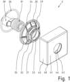
- FIG 3 a wall rosette arrangement 2 according to the invention is shown in an exploded view.
- An S-arch 30 is present on the building side. It has two threaded shoulders 31, one of which protrudes from the wall level.
- a fastening element 20 has an annular shoulder 21 with a threaded hole 23 with which it can be screwed onto the threaded shoulder 31 of the S-bend 30. Key surfaces 22 are formed on the shoulder 21 and an O-ring 27 is fitted.
- a receptacle for another sealing ring 26 is formed on the back of the pressure disk 24.
- Figure 2 shows the back of the wall rosette 40 in a perspective view. It has a front panel 41 with a through opening 43 and is surrounded by a frame 42, so that a cuboid, open at the back Hollow body is formed.
- a cup-shaped receptacle 44 adjoins the feed-through opening 43 on the back of the front plate 42, the inner diameter of which is larger than the diameter of the feed-through opening 43, since the radial area in between is required to accommodate the fastening element 20 including the O-ring.
- FIG 3 a fastening element 20' is shown for a second embodiment of a wall rosette arrangement 3 designed according to the invention.
- the fastening element 20' has been screwed onto a threaded shoulder 31, which protrudes from a wall plane, until it rests on the wall surface.
- the fastening element 20 ' has an annular shoulder 21' with which it can be screwed onto the threaded shoulder 31 of the S-bend 30.
- a circumferential recess in the form of a groove 27' with a trapezoidal cross-section is provided on the shoulder 21', and two parallel key surfaces 22' are formed on the shoulder 21'.
- the shoulder 21' is adjoined by an annular pressure disk 24', which has a larger diameter than the shoulder 21' and is supported on it via webs 25'.
- a tooth structure with a plurality of positioning notches 28' is formed on the outer circumference of the pressure disk 24'.
- a corresponding wall rosette 40 is in Fig. 4 shown in perspective view. It has a front panel 41' with a through opening 43'. The front panel 41' is surrounded by a frame 42', so that a cuboid hollow body that is open at the rear is formed. Several locking pins 44' are connected to the back of the front surface 41' of the wall rosette 40', so that the locking pins 44' protrude into the cavity and form a receiving ring 45'. In addition, webs 46' are formed at four positions on the inside of the frame 42'.
- FIG. 5 shows the entire wall rosette arrangement 3 from the back.
- the wall rosette 40' is attached to the fastening element 20' in that the front panel 41 'has a plurality of resilient locking pins 44' on its rear side, which protrude vertically and which can each be snapped into the groove 27' on the shoulder 21' with a locking pin 44'.
- the webs 46' each engage in one of the numerous positioning notches 28' which are formed on the outer circumference of the annular pressure disk 24' of the fastening element 20'.
- a receptacle for another sealing ring 26' is formed on the back of the pressure disk 24'.
- Figure 6 shows the entire wall rosette arrangement 3 in a perspective sectional view, in particular the engagement of the locking pins 44 'in the groove 27' being visible.
Abstract
Wandrosettenanordnung (2) mit einer rechteckigen Wandrosette (40) für eine Aufputz-Sanitärarmatur, wenigstens umfassend einen umlaufenden Rahmen (42) und eine Frontplatte (41) mit einer Durchführungsöffnung (43) für einen gebäudeseitig vorhandenen S-Bogen (30) oder ein Rohrende mit Außengewinde,dadurch gekennzeichnet, dass- ein Befestigungselement (20) vorgesehen ist, das wenigstens einen ringförmigen Absatz (21) mit einem Innengewinde umfasst, über welches das Befestigungselement (20) auf einen Gewindeabsatz (31) des S-Bogens (30) aufschraubbar ist und an seinem Außenumfang mit wenigstens einem Formschlussmittel zur Drehmomentübertragung versehen ist;- dass das Befestigungselement (20) mit einer ringförmigen Andruckscheibe (24) verbunden ist oder eine solche besitzt, welche auf ihrer der Wand zuzuwendenden Rückseite wenigstens einen Dichtring (26) hält;- dass das Befestigungselement (20) an seinem Außenumfang mit wenigstens einem Klemmmittel versehen ist, über das die Wandrosette durch axialen Schub in Richtung einer Wandfläche auf den Absatz (21) des Befestigungselements (20) aufklemmbar und in der erreichten Position verdrehsicher zu halten ist;- dass an der Wandrosette (40) durch den Rahmen (42) und die Frontplatte (41) ein nach hinten offener, quaderförmiger Hohlkörper gebildet ist, in welchem das Befestigungselement (20) aufgenommen ist; und- dass die Wandrosette (40) an der rückwärtigen Seite der Frontplatte (41) in eine Aufnahme (44) übergeht.Wall rosette arrangement (2) with a rectangular wall rosette (40) for an exposed sanitary fitting, comprising at least one circumferential frame (42) and a front panel (41) with a through opening (43) for an S-bend (30) on the building side or a pipe end with external thread, characterized in that - a fastening element (20) is provided which comprises at least one annular shoulder (21) with an internal thread, via which the fastening element (20) can be screwed onto a threaded shoulder (31) of the S-arm (30). and is provided on its outer circumference with at least one form-fitting means for torque transmission; - that the fastening element (20) is connected to an annular pressure disk (24) or has one which holds at least one sealing ring (26) on its rear side facing the wall; - that the fastening element (20) is provided on its outer circumference with at least one clamping means, via which the wall rosette can be clamped onto the shoulder (21) of the fastening element (20) by axial thrust in the direction of a wall surface and held in the position reached so that it cannot rotate; - that on the wall rosette (40) a cuboid-shaped hollow body which is open to the rear is formed by the frame (42) and the front panel (41), in which the fastening element (20) is accommodated; and- that the wall rosette (40) merges into a receptacle (44) on the rear side of the front panel (41).
Description
Die Erfindung betrifft eine Wandrosettenanordnung mit einer rechteckigen Wandrosette für eine Aufputz-Sanitärarmatur mit den Merkmalen des Oberbegriffs des Anspruchs 1.The invention relates to a wall rosette arrangement with a rectangular wall rosette for an exposed sanitary fitting with the features of the preamble of claim 1.
Um eine Aufputz-Sanitärarmatur wie beispielsweise eine Brausearmatur montieren zu können, sind an einer gebäudeseitig vorbereiteten Wasserzapfstelle üblicherweise sogenannte S-Bögen in die Muffenenden der Warm- und Kaltwasserleitungen eingesetzt. Hierbei handelt es sich um wasserleitende Teile, die beidseitig mit Gewinden versehen sind. Die beiden Gewindeabsätze liegen parallel versetzt zueinander. Durch Drehen der beiden S-Bögen können leichte Abweichungen des Stichmaßes zwischen den beiden Muffenenden vom Sollmaß ausgeglichen werden. Auch können darüber bei der Feinmontage kleine Schiefstellungen behoben werden, damit die Armatur exakt horizontal ausgerichtet ist. Um die S-Bögen und die sie umgebenden Wandvertiefungen zu überdecken, werden Wandrosetten auf die aus der Wand heraustretenden Gewindeabsätze der S-Bögen gesetzt. Bei runden Wandrosetten reicht es aus, diese auf den Gewindeabsatz zu schieben. Auch kann das vorhandene Gewinde genutzt werden, um die Wandrosette auf den Gewindeabsatz aufzudrehen und gegen die Wandoberfläche zu verspannen.In order to be able to install a surface-mounted sanitary fitting such as a shower fitting, so-called S-bends are usually inserted into the socket ends of the hot and cold water pipes at a water tap point prepared on the building side. These are water-conducting parts that have threads on both sides. The two thread shoulders are parallel and offset from one another. By turning the two S-bends, slight deviations in the pitch between the two sleeve ends from the target dimension can be compensated for. Small misalignments can also be corrected during fine assembly so that the fitting is aligned exactly horizontally. In order to cover the S-bows and the wall recesses surrounding them, wall rosettes are placed on the threaded shoulders of the S-bows that emerge from the wall. For round wall rosettes, it is sufficient to push them onto the threaded shoulder. The existing thread can also be used to screw the wall rosette onto the threaded shoulder and clamp it against the wall surface.
Beide Formen sind jedoch für eckige Wandrosetten nicht gut geeignet, da bei ihnen nicht sichergestellt werden kann, dass die Kanten der montierten Wandrosette nach dem Anbringen der Wandrosette exakt horizontal und vertikal ausgerichtet sind und/oder dass diese gewünschte Ausrichtung dauerhaft beibehalten wird. Schief stehende eckige Wandrosetten werden aus optischen Gründen als nachteilig angesehen.However, both shapes are not well suited for angular wall rosettes, as they cannot ensure that the edges of the mounted wall rosette are aligned exactly horizontally and vertically after the wall rosette has been attached and/or that this desired alignment is permanently maintained. Angled wall rosettes that are crooked are considered disadvantageous for visual reasons.
Aus der
Die Aufgabe der vorliegenden Erfindung besteht darin, eine eckige Wandrosette für eine Aufputz-Sanitärarmatur so zu verbessern, dass diese bei der Montage exakt auszurichten ist und dass die Wandrosetten auch im späteren Gebrauch, z.B. beim Reinigen, nicht unbeabsichtigt verdreht werden können.The object of the present invention is to improve a square wall rosette for a surface-mounted sanitary fitting so that it can be precisely aligned during installation and that the wall rosettes cannot be accidentally twisted even during later use, for example when cleaning.
Diese Aufgabe wird nach der vorliegenden Erfindung durch eine Wandrosettenanordnung mit den Merkmalen des Anspruchs 1 gelöst.This object is achieved according to the present invention by a wall rosette arrangement with the features of claim 1.
Die Erfindung beruht darauf, dass ein Befestigungselement zwischen dem S-Bogen und der Wandrosette eingefügt wird, bei dem wenigstens ein ringförmiger Absatz vorhanden ist oder welches selbst insgesamt ringförmig ist. Der zur Verbindung vorgesehene Absatz besitzt ein Innengewinde, über das er auf den Gewindeabsatz des S-Bogens aufschraubbar ist, und zwar insbesondere so weit, dass Wandkontakt hergestellt und eine axiale Verspannung zwischen Wand und S-Bogen erreicht wird. Dadurch ist das Befestigungselement verdrehsicher festgelegt.The invention is based on the fact that a fastening element is inserted between the S-bend and the wall rosette, in which at least one annular shoulder is present or which itself is annular overall. The shoulder provided for connection has an internal thread through which it can be screwed onto the threaded shoulder of the S-bend, in particular to such an extent that wall contact is established and axial bracing between the wall and S-bend is achieved. As a result, the fastening element is secured against rotation.
Die Verdrehsicherheit des Befestigungselements kann auch durch ein Untermaß des Gewindes erreicht werden oder z. B. durch Verkleben des Befestigungselements auf dem Gewindeabsatz.The security of the fastening element against rotation can also be achieved by making the thread undersized or e.g. B. by gluing the fastener to the threaded shoulder.
Am Befestigungselement und/oder an der Wandrosette ist wenigstens ein Klemmmittel vorgesehen, über das die Wandrosette durch axialen Schub in Richtung der Wandfläche, also ohne Schraubgewinde oder zusätzliche Befestigungsmittel, auf das Befestigungselement aufklemmbar ist und in der erreichten Position verdrehsicher gehalten wird.At least one clamping means is provided on the fastening element and/or on the wall rosette, via which the wall rosette can be clamped onto the fastening element by axial thrust in the direction of the wall surface, i.e. without a screw thread or additional fastening means, and is held in the position reached so that it cannot rotate.
Insbesondere ist das Klemmmittel ein O-Ring, der aus einem Elastomer gefertigt ist.In particular, the clamping means is an O-ring that is made of an elastomer.
Die zugehörige Wandrosette hat eine rechteckige Frontplatte und einen umlaufenden Rahmen, so dass ein einseitig offener, quaderförmiger Hohlkörper gebildet ist. Die Frontplatte hat eine Durchführungsöffnung für einen gebäudeseitig vorhandenen S-Bogens.The associated wall rosette has a rectangular front panel and a surrounding frame, so that a cuboid-shaped hollow body that is open on one side is formed. The front panel has an opening for an S-bend on the building side.
Um diese Durchführungsöffnung herum schließt sich an die Frontplatte eine insbesondere becherförmige Aufnahme an, die auf den zugehörigen Absatz am Befestigungselement mit dem Klemmmittel wie insbesondere einem O-Ring oder einem anderen elastomeren Element aufklemmbar ist. Dafür besitzt die becherförmige Aufnahme einen Innendurchmesser, der so in Bezug auf den Außendurchmesser des O-Ring oder eines anderen elastomeren Elements abgestimmt ist, dass eine Kompression mit solchen Kräften möglich ist, die durch manuelles, axiales Aufschieben der Wandrosette auf das Befestigungselement hervorrufbar sind.Around this passage opening, the front panel is adjoined by a particularly cup-shaped receptacle, which can be clamped onto the associated shoulder on the fastening element with the clamping means, in particular an O-ring or another elastomeric element. For this purpose, the cup-shaped receptacle has an inner diameter that is coordinated with respect to the outer diameter of the O-ring or another elastomeric element so that compression is possible with forces that can be caused by manually pushing the wall rosette axially onto the fastening element.
Durch die Kompression wird eine reibschlüssige Klemmung bewirkt und die einmal eingestellte Winkellage wird im Gebrauch der Sanitärarmatur beibehalten und kann nur mit größerem Kraftaufwand verändert werden, so dass eine unbeabsichtigte oder gar selbsttätige Verdrehung der Wandrosette ausgeschlossen ist.The compression causes a frictional clamping and the angular position, once set, is maintained when the sanitary fitting is in use and can only be changed with great effort, so that unintentional or even automatic twisting of the wall rosette is ruled out.
Um die Verspannung gegen die Wand einfach bewirken zu können, ist am Außenumfang des Befestigungselements wenigstens ein Formschlussmittel vorgesehen. Dabei kann es sich um wenigstens ein Paar von Schlüsselflächen handeln, an denen ein Gabelschlüssel angesetzt werden kann.In order to be able to easily effect the tension against the wall, at least one form-fitting means is provided on the outer circumference of the fastening element. This can be at least one pair of wrench surfaces on which an open-end wrench can be attached.
Möglich ist auch, am Außenrand eine Riffelung auszubilden, um das Befestigungselement leichter greifen zu können und so ein höheres Drehmoment übertragen zu können.It is also possible to form a corrugation on the outer edge in order to be able to grip the fastening element more easily and thus to be able to transmit a higher torque.
Wenn eine höhere Drehmomentübertragung möglich ist, dann kann es vorteilhaft sein, das Innengewinde an dem insbesondere aus thermoplastischem Kunststoff gefertigten Befestigungselement mit leichtem Untermaß in Form einer Übergangspassung herzustellen, so dass die Klemmkräfte erhöht sind und eine spätere unbeabsichtigte Verdrehung auf dem Gewindeabsatz des S-Bogens vermieden wird.If a higher torque transmission is possible, then it can be advantageous to produce the internal thread on the fastening element, which is made in particular from thermoplastic material, with a slight undersize in the form of a transition fit, so that the clamping forces are increased and a later unintentional rotation on the thread shoulder of the S-bend is prevented is avoided.
Ein zusätzlicher Absatz am Befestigungselement bildet eine im Durchmesser größere Andruckscheibe, die an die Wand angelegt wird, wenn das Befestigungselement auf den S-Bogen aufgeschraubt wird. Die Andruckscheibe trägt auf ihrer der Wand zuzuwendenden Rückseite wenigstens einen Dichtring. Als Zusatzfunktion wird durch das Befestigungselement für die Wandrosette die Abdichtung der Wandebene um den S-Bogen herum erreicht, so dass Wasser nicht über die in der Umgebung stets vorhandene Ausnehmung im Wandbelag in die Wand eindringen kann.An additional shoulder on the fastening element forms a pressure washer with a larger diameter, which is placed against the wall when the fastening element is screwed onto the S-bend. The pressure disk has at least one sealing ring on its back facing the wall. As an additional function, the fastening element for the wall rosette seals the wall plane around the S-bend, so that water cannot penetrate into the wall via the recess in the wall covering that is always present in the area.
Bei einer ersten Ausführungsform besitzt das Befestigungselement ebenfalls einen ringförmigen Absatz, der für die Verbindung mit dem S-Bogen vorgesehen ist. Derselbe Absatz oder ein weiterer Absatz kann den O-Ring aufnehmen, auf den eine becherförmige Aufnahme, die an der Rückseite der Frontfläche der Wandrosette um die Durchgangsöffnung herum ausgebildet ist, aufklemmbar ist.In a first embodiment, the fastening element also has an annular shoulder which is intended for connection to the S-bend. The same shoulder or another shoulder can accommodate the O-ring, onto which a cup-shaped receptacle, which is formed on the back of the front surface of the wall rosette around the through opening, can be clamped.
Für die Ausbildung der Klemmverbindung zwischen dem Befestigungselement und der becherförmigen Aufnahme an der Wandrosette sind folgende Varianten möglich:
Nach einer Ausführungsform ist der Außenumfang des für die Befestigung vorgesehenen Absatzes am Befestigungselement zylindrisch, ebenso wie der Innenumfang der Aufnahme zylindrisch ist. Damit wird die Klemmwirkung allein durch die Abstimmung des Innendurchmessers der Aufnahme an der Wandrosette und dem Außendurchmesser des O-Rings bestimmt.The following variants are possible for forming the clamp connection between the fastening element and the cup-shaped receptacle on the wall rosette:
According to one embodiment, the outer circumference of the shoulder provided for fastening on the fastening element is cylindrical, just as the inner circumference of the receptacle is cylindrical. This means that the clamping effect is determined solely by matching the inner diameter of the mount on the wall rosette and the outer diameter of the O-ring.
Der Außenumfang des Befestigungselements kann auch konisch sein, wobei die becherförmige Aufnahme an der Wandrosette zylindrisch ist oder umgekehrt. Der Konuswinkel sollte kleiner als 5° sein, eher kleiner als 2° sein. Die Ausführung mit einem Konus hat den Vorteil, dass die Stärke der Kompression des O-Rings und darüber die Klemmkraft beim Aufschieben der Wandrosette einstellbar sind. Da sich der Innendurchmesser der Aufnahme konischen zur Rückseite der Frontplatte hin verjüngt, verjüngt sich auch der Ringspalt zwischen Absatz und Aufnahme und der dort befindliche O-Ring wird stärker komprimiert, je weiter die Rosette auf dem Befestigungselement axial vorbewegt wird. Um die Klemmkraft einzustellen, kann das Befestigungselement auf dem Gewindeabsatz des S-Bogens axial näher zur Wand oder etwas weiter weg davon positioniert werden.The outer circumference of the fastening element can also be conical, with the cup-shaped receptacle on the wall rosette being cylindrical or vice versa. The cone angle should be less than 5°, rather less than 2°. The design with a cone has the advantage that the strength of the compression of the O-ring and the clamping force when pushing on the wall rosette can be adjusted. Since the inner diameter of the receptacle tapers conically towards the back of the front panel, the annular gap between the shoulder and receptacle also tapers and the O-ring located there is compressed more strongly the further the rosette is moved axially on the fastening element. To adjust the clamping force, the fastening element on the threaded shoulder of the S-bend can be positioned axially closer to the wall or slightly further away from it.
Bei einer weiteren möglichen Ausführungsform der Erfindung ist vorgesehen, dass das Klemmmittel durch wenigstens einen federnden Zapfen gebildet ist, der an die rückwärtige Seite der Frontplatte der Wandrosette angebunden ist und der mit einem Rastvorsprung in eine Vertiefung am Absatz des Befestigungselements einrastbar ist. In axialer Richtung ergibt sich über den Rastvorsprung eine formschlüssige Sicherung. Die Verdrehsicherung ist außerdem reibschlüssig, da der federnde Zapfen auf den Absatz drückt.In a further possible embodiment of the invention it is provided that the clamping means is formed by at least one resilient pin, which is connected to the rear side of the front panel of the wall rosette and which can be snapped into a recess on the shoulder of the fastening element with a locking projection. In the axial direction, the locking projection creates a positive lock. The anti-twist device is also frictional, as the resilient pin presses on the heel.
Bevorzugt ist die Klemmwirkung dadurch erhöht, dass die Vertiefung eine sich über den Außenumfang erstreckende Rille ist und dass um die Durchführungsöffnung der Wandrosette herum mehrere federnde Zapfen vorgesehen sind, die in die Rille eingreifen.The clamping effect is preferably increased in that the recess is a groove extending over the outer circumference and that around the There are several resilient pins around the opening of the wall rosette, which engage in the groove.
Die federnden Zapfen können Teil der becherförmigen Aufnahme an der Rückseite der Wandrosette sein, oder sie bilden in runder Anordnung einen Kranz, der eine solche Aufnahme ersetzt.The resilient pins can be part of the cup-shaped receptacle on the back of the wall rosette, or they can form a circular arrangement that replaces such a receptacle.
Der Reibschluss kann bei dieser Ausführungsform noch dadurch erhöht sein, dass an dem Absatz des Befestigungselements ein elastomerer Dichtring aufgezogen ist, wie bei der ersten Ausführungsform auch, und dass die Zapfen auf den Dichtring auffedern oder über den Dichtring hinweg in die Vertiefung eingreifen und dabei zugleich den Dichtring kontaktieren. Denkbar ist dabei auch, den zusätzlichen Dichtring direkt in der Rille aufzuziehen.In this embodiment, the frictional connection can be further increased by the fact that an elastomeric sealing ring is mounted on the shoulder of the fastening element, as in the first embodiment, and that the pins spring onto the sealing ring or engage over the sealing ring into the recess and at the same time contact the sealing ring. It is also conceivable to mount the additional sealing ring directly in the groove.
Um die Verdrehsicherung der Wandrosette zu verbessern, kann bei beiden Ausführungsformen des Befestigungselements vorgesehen sein, dass am Außenumfang desjenigen Absatzes, der den größten Durchmesser aufweist, also in der Regel am Außenumfang der Andruckscheibe, mehrere Positionierungskerben ausgebildet sind, die in kleiner Winkelteilung zueinander angeordnet sind. Diese Positionierungskerben können zugleich auch eine geriffelte Struktur als Formschlussmittel zur Drehmomentübertragung bilden. Zusätzlich ist wenigstens ein Zapfen oder Steg an die Innenseite des Rahmens der Wandrosette angeformt oder sonstwie befestigt, der in eine von mehreren Positionierungskerben eingreift, wenn die Wandrosette axial auf das Befestigungselement aufgeschoben wird.In order to improve the anti-twist protection of the wall rosette, it can be provided in both embodiments of the fastening element that a plurality of positioning notches are formed on the outer circumference of the shoulder that has the largest diameter, i.e. usually on the outer circumference of the pressure disk, which are arranged at a small angular pitch to one another . These positioning notches can also form a corrugated structure as a form-fitting means for torque transmission. In addition, at least one pin or web is formed or otherwise attached to the inside of the frame of the wall rosette, which engages in one of several positioning notches when the wall rosette is pushed axially onto the fastening element.
Die Erfindung wird nachfolgend mit Bezug auf die in den Zeichnungen dargestellten Ausführungsbeispiele näher erläutert. Die Figuren zeigen im Einzelnen:
- Fig. 1
- eine erste Ausführungsform einer Wandrosettenanordnung in einer Explosionsansicht;
- Fig. 2
- eine Wandrosette in perspektivischer Ansicht von der Rückseite her gesehen;
- Fig. 3
- ein Befestigungselement für eine zweite Ausführungsform einer Wandrosettenanordnung in perspektivischer Ansicht;
- Fig. 4
- eine Wandrosette für die zweite Ausführungsform in perspektivischer Ansicht von der Rückseite her gesehen;
- Fig. 5
- die zweite Ausführungsform der Wandrosettenanordnung, in perspektivischer Ansicht von der Rückseite her gesehen, und
- Fig. 6
- die zweite Ausführungsform der Wandrosettenanordnung, in perspektivischer Schnittansicht.
- Fig. 1
- a first embodiment of a wall rosette arrangement in an exploded view;
- Fig. 2
- a wall rosette in a perspective view seen from the back;
- Fig. 3
- a fastening element for a second embodiment of a wall rosette arrangement in a perspective view;
- Fig. 4
- a wall rosette for the second embodiment seen in a perspective view from the back;
- Fig. 5
- the second embodiment of the wall rosette arrangement, seen in a perspective view from the back, and
- Fig. 6
- the second embodiment of the wall rosette arrangement, in a perspective sectional view.
In
Ein Befestigungselement 20 besitzt einen ringförmigen Absatz 21 mit einer Gewindebohrung 23, mit der es auf dem Gewindeabsatz 31 des S-Bogens 30 aufschraubbar ist. Am Absatz 21 sind Schlüsselflächen 22 ausgebildet und es ist ein O-Ring 27 aufgezogen.A
An den Absatz 21 schließt sich wie ein Kragen eine ringförmige Andruckscheibe 24 an, die über Stege 25 versteift ist. An der Rückseite der Andruckscheibe 24 ist eine Aufnahme für einen weiteren Dichtring 26 ausgebildet. Beim Aufschrauben des Befestigungselements 20 auf den S-Bogen 30 wird der Dichtring 26 über die Andruckscheibe 24 an die Wandoberfläche angepresst.An
In
Das Befestigungselement 20' besitzt einen ringförmigen Absatz 21', mit dem es auf den Gewindeabsatz 31 des S-Bogens 30 aufschraubbar ist. Am Absatz 21' ist eine umlaufende Vertiefung in Form einer Rille 27' mit trapezförmigem Querschnitt vorgesehen, und es sind an dem Absatz 21' zwei parallele Schlüsselflächen 22' ausgebildet. An den Absatz 21' schließt sich eine ringförmige Andruckscheibe 24' an, die einen größeren Durchmesser besitzt als der Absatz 21' und an diesem über Stege 25' abgestützt ist. Am Außenumfang der Andruckscheibe 24' ist eine Zahnstruktur mit einer Vielzahl von Positionierungskerben 28' ausgebildet.The fastening element 20 'has an annular shoulder 21' with which it can be screwed onto the threaded
Eine zugehörige der Wandrosette 40 ist in
- 2,32.3
- WandrosettenanordnungWall rosette arrangement
- 20; 20'20; 20'
- Befestigungselementfastener
- 21; 2121; 21
- AbsatzParagraph
- 2323
- GewindebohrungThreaded hole
- 22; 22'22; 22'
- Schlüsselflächenkey surfaces
- 24; 24'24; 24'
- Andruckscheibepressure washer
- 25; 25'25; 25'
- StegeBridges
- 26; 26'26; 26'
- Dichtringsealing ring
- 2727
- O-RingO-ring
- 27'27'
- Rillegroove
- 28'28'
- PositionierungskerbenPositioning notches
- 3030
- S-BogenS-bow
- 3131
- GewindeabsatzThreaded heel
- 40; 40'40; 40'
- WandrosetteWall rosette
- 41; 41'41; 41'
- FrontplatteFront panel
- 42; 42'42; 42'
- RahmenFrame
- 43; 43'43; 43'
- DurchführungsöffnungPassage opening
- 4444
- becherförmige Aufnahmecup-shaped holder
- 44'44'
- Rastzapfenlocking pin
- 45'45'
- AufnahmekranzReceiving wreath
- 46'46'
- StegeBridges
Claims (9)
dadurch gekennzeichnet, dass
characterized in that
Applications Claiming Priority (1)
| Application Number | Priority Date | Filing Date | Title |
|---|---|---|---|
| DE202022121077 | 2022-08-19 |
Publications (1)
| Publication Number | Publication Date |
|---|---|
| EP4324990A1 true EP4324990A1 (en) | 2024-02-21 |
Family
ID=87695863
Family Applications (1)
| Application Number | Title | Priority Date | Filing Date |
|---|---|---|---|
| EP23191860.8A Pending EP4324990A1 (en) | 2022-08-19 | 2023-08-17 | Wall rosette assembly with rectangular wall rosette for a plaster sanitary fitting |
Country Status (1)
| Country | Link |
|---|---|
| EP (1) | EP4324990A1 (en) |
Citations (10)
| Publication number | Priority date | Publication date | Assignee | Title |
|---|---|---|---|---|
| US3615108A (en) * | 1969-03-24 | 1971-10-26 | Sajar Plastics Inc | Escutcheon plate |
| US5447338A (en) * | 1993-04-23 | 1995-09-05 | Senju Sprinkler Company Limited | Escutcheon for use with sprinkler head |
| DE102005007778A1 (en) | 2005-02-19 | 2006-08-24 | American Standard Europe B.V.B.A. | Device for covering a wall connection for a sanitary fitting comprises a rose which slides onto and fixes to a wall connection via an opening |
| US20080211226A1 (en) * | 2007-03-01 | 2008-09-04 | Accor Technology, Inc. | Enhanced escutcheon cover plate |
| CN103290889B (en) * | 2012-10-19 | 2015-05-20 | 宁波敏宝卫浴五金水暖洁具有限公司 | Fixing method and fixing structure for square wall cover |
| DE102014010130A1 (en) * | 2014-07-09 | 2016-01-14 | Grohe Ag | Covering device for a connection piece of a water fitting |
| DE102015000743A1 (en) * | 2015-01-19 | 2016-07-21 | Ritterwand Gmbh & Co. Kg Metall-Systembau | rosette |
| EP3124709A1 (en) * | 2015-07-30 | 2017-02-01 | Ideal Standard International NV | Rosette device |
| EP3162970A1 (en) * | 2015-10-28 | 2017-05-03 | Oras Oy | Covering rosette for a concealed sanitary fitting |
| US20220098848A1 (en) * | 2020-09-29 | 2022-03-31 | Brent Waterman | Pipe covering |
-
2023
- 2023-08-17 EP EP23191860.8A patent/EP4324990A1/en active Pending
Patent Citations (10)
| Publication number | Priority date | Publication date | Assignee | Title |
|---|---|---|---|---|
| US3615108A (en) * | 1969-03-24 | 1971-10-26 | Sajar Plastics Inc | Escutcheon plate |
| US5447338A (en) * | 1993-04-23 | 1995-09-05 | Senju Sprinkler Company Limited | Escutcheon for use with sprinkler head |
| DE102005007778A1 (en) | 2005-02-19 | 2006-08-24 | American Standard Europe B.V.B.A. | Device for covering a wall connection for a sanitary fitting comprises a rose which slides onto and fixes to a wall connection via an opening |
| US20080211226A1 (en) * | 2007-03-01 | 2008-09-04 | Accor Technology, Inc. | Enhanced escutcheon cover plate |
| CN103290889B (en) * | 2012-10-19 | 2015-05-20 | 宁波敏宝卫浴五金水暖洁具有限公司 | Fixing method and fixing structure for square wall cover |
| DE102014010130A1 (en) * | 2014-07-09 | 2016-01-14 | Grohe Ag | Covering device for a connection piece of a water fitting |
| DE102015000743A1 (en) * | 2015-01-19 | 2016-07-21 | Ritterwand Gmbh & Co. Kg Metall-Systembau | rosette |
| EP3124709A1 (en) * | 2015-07-30 | 2017-02-01 | Ideal Standard International NV | Rosette device |
| EP3162970A1 (en) * | 2015-10-28 | 2017-05-03 | Oras Oy | Covering rosette for a concealed sanitary fitting |
| US20220098848A1 (en) * | 2020-09-29 | 2022-03-31 | Brent Waterman | Pipe covering |
Similar Documents
| Publication | Publication Date | Title |
|---|---|---|
| EP2225811B1 (en) | Connection fitting | |
| DE19637074A1 (en) | Coupling device for connecting two pipe elements | |
| LU84418A1 (en) | CLUTCH ELEMENT | |
| DE202006018110U1 (en) | Plug-type connector for inserting into a wall opening comprises a housing for inserting into an opening in a wall and fixed using a flange formed as a one-piece flange plate | |
| EP1450052B1 (en) | Connection fitting | |
| EP0632872B1 (en) | Insertable type safety coupling for pressure pipes | |
| DE102004007745B3 (en) | Plug-in fitting with a clamping ring | |
| DE69927031T2 (en) | PIPE COUPLING | |
| EP0327494A1 (en) | Safety plug coupling, especially for pressurized-air conduits | |
| EP0964493A2 (en) | Angular cable entry with a disconnecting point between the two legs | |
| EP1321589B1 (en) | Anchorage fitting for sanitary mounting | |
| EP2918354B1 (en) | Pressing attachment for axially pressing workpieces | |
| EP4324990A1 (en) | Wall rosette assembly with rectangular wall rosette for a plaster sanitary fitting | |
| DE19628780B4 (en) | Arrangement for quick attachment of a sanitary fitting | |
| DE102022121077A1 (en) | Wall rosette arrangement with a rectangular wall rosette for a surface-mounted sanitary fitting | |
| DE102007059329A1 (en) | Plug-in connector for piping, has spring unit arranged between radial shoulder and outer part, and retaining unit pushed out from recess at spigot or in opening of outer part in locking position, so that spigot is detached from outer part | |
| DE19715293B4 (en) | Plug connection for pipelines | |
| DE4110809A1 (en) | Furniture assembly mounting unit | |
| DE4102048C2 (en) | Sanitary fitting | |
| DE4420470C2 (en) | Coupling, in particular for sanitary and supply facilities and lines or the like | |
| DE60017342T2 (en) | Fixing device for profiles | |
| DE10357646B4 (en) | Wall bushing | |
| DE10236183B4 (en) | Tube luminaire with sealing device for tube elements | |
| DE2412679A1 (en) | Wall connection for water fitting - has polyamide baseplate and can be connected in differing positions | |
| DE4443545B4 (en) | Connectors |
Legal Events
| Date | Code | Title | Description |
|---|---|---|---|
| PUAI | Public reference made under article 153(3) epc to a published international application that has entered the european phase |
Free format text: ORIGINAL CODE: 0009012 |
|
| STAA | Information on the status of an ep patent application or granted ep patent |
Free format text: STATUS: THE APPLICATION HAS BEEN PUBLISHED |
|
| AK | Designated contracting states |
Kind code of ref document: A1 Designated state(s): AL AT BE BG CH CY CZ DE DK EE ES FI FR GB GR HR HU IE IS IT LI LT LU LV MC ME MK MT NL NO PL PT RO RS SE SI SK SM TR |