EP4324322A2 - Panneau de commande, appareil de commutation autopropulsé et dispositif d'alimentation - Google Patents
Panneau de commande, appareil de commutation autopropulsé et dispositif d'alimentation Download PDFInfo
- Publication number
- EP4324322A2 EP4324322A2 EP23185300.3A EP23185300A EP4324322A2 EP 4324322 A2 EP4324322 A2 EP 4324322A2 EP 23185300 A EP23185300 A EP 23185300A EP 4324322 A2 EP4324322 A2 EP 4324322A2
- Authority
- EP
- European Patent Office
- Prior art keywords
- panel assembly
- rod
- power device
- self
- propelled
- Prior art date
- Legal status (The legal status is an assumption and is not a legal conclusion. Google has not performed a legal analysis and makes no representation as to the accuracy of the status listed.)
- Pending
Links
- 230000006835 compression Effects 0.000 claims description 21
- 238000007906 compression Methods 0.000 claims description 21
- 238000006073 displacement reaction Methods 0.000 claims description 14
- 230000001133 acceleration Effects 0.000 claims description 8
- 241001417527 Pempheridae Species 0.000 claims description 5
- 239000002689 soil Substances 0.000 claims description 3
- 230000000712 assembly Effects 0.000 description 25
- 238000000429 assembly Methods 0.000 description 25
- 238000000034 method Methods 0.000 description 7
- 230000001960 triggered effect Effects 0.000 description 5
- 230000009471 action Effects 0.000 description 3
- 230000008901 benefit Effects 0.000 description 3
- 230000008569 process Effects 0.000 description 3
- 238000005516 engineering process Methods 0.000 description 2
- 230000001360 synchronised effect Effects 0.000 description 2
- 230000008859 change Effects 0.000 description 1
- 230000000994 depressogenic effect Effects 0.000 description 1
- 230000000694 effects Effects 0.000 description 1
- 239000002184 metal Substances 0.000 description 1
- 238000012986 modification Methods 0.000 description 1
- 230000004048 modification Effects 0.000 description 1
- 238000006467 substitution reaction Methods 0.000 description 1
Images


Classifications
-
- A—HUMAN NECESSITIES
- A01—AGRICULTURE; FORESTRY; ANIMAL HUSBANDRY; HUNTING; TRAPPING; FISHING
- A01D—HARVESTING; MOWING
- A01D34/00—Mowers; Mowing apparatus of harvesters
- A01D34/01—Mowers; Mowing apparatus of harvesters characterised by features relating to the type of cutting apparatus
- A01D34/412—Mowers; Mowing apparatus of harvesters characterised by features relating to the type of cutting apparatus having rotating cutters
- A01D34/63—Mowers; Mowing apparatus of harvesters characterised by features relating to the type of cutting apparatus having rotating cutters having cutters rotating about a vertical axis
- A01D34/82—Other details
- A01D34/824—Handle arrangements
-
- A—HUMAN NECESSITIES
- A01—AGRICULTURE; FORESTRY; ANIMAL HUSBANDRY; HUNTING; TRAPPING; FISHING
- A01D—HARVESTING; MOWING
- A01D34/00—Mowers; Mowing apparatus of harvesters
- A01D34/01—Mowers; Mowing apparatus of harvesters characterised by features relating to the type of cutting apparatus
- A01D34/412—Mowers; Mowing apparatus of harvesters characterised by features relating to the type of cutting apparatus having rotating cutters
- A01D34/63—Mowers; Mowing apparatus of harvesters characterised by features relating to the type of cutting apparatus having rotating cutters having cutters rotating about a vertical axis
- A01D34/67—Mowers; Mowing apparatus of harvesters characterised by features relating to the type of cutting apparatus having rotating cutters having cutters rotating about a vertical axis hand-guided by a walking operator
- A01D34/68—Mowers; Mowing apparatus of harvesters characterised by features relating to the type of cutting apparatus having rotating cutters having cutters rotating about a vertical axis hand-guided by a walking operator with motor driven cutters or wheels
- A01D34/6806—Driving mechanisms
-
- A—HUMAN NECESSITIES
- A01—AGRICULTURE; FORESTRY; ANIMAL HUSBANDRY; HUNTING; TRAPPING; FISHING
- A01D—HARVESTING; MOWING
- A01D34/00—Mowers; Mowing apparatus of harvesters
- A01D34/006—Control or measuring arrangements
-
- A—HUMAN NECESSITIES
- A01—AGRICULTURE; FORESTRY; ANIMAL HUSBANDRY; HUNTING; TRAPPING; FISHING
- A01D—HARVESTING; MOWING
- A01D34/00—Mowers; Mowing apparatus of harvesters
- A01D34/01—Mowers; Mowing apparatus of harvesters characterised by features relating to the type of cutting apparatus
- A01D34/02—Mowers; Mowing apparatus of harvesters characterised by features relating to the type of cutting apparatus having reciprocating cutters
- A01D34/30—Driving mechanisms for the cutters
- A01D34/37—Driving mechanisms for the cutters electric
-
- A—HUMAN NECESSITIES
- A01—AGRICULTURE; FORESTRY; ANIMAL HUSBANDRY; HUNTING; TRAPPING; FISHING
- A01D—HARVESTING; MOWING
- A01D34/00—Mowers; Mowing apparatus of harvesters
- A01D34/01—Mowers; Mowing apparatus of harvesters characterised by features relating to the type of cutting apparatus
- A01D34/412—Mowers; Mowing apparatus of harvesters characterised by features relating to the type of cutting apparatus having rotating cutters
- A01D34/63—Mowers; Mowing apparatus of harvesters characterised by features relating to the type of cutting apparatus having rotating cutters having cutters rotating about a vertical axis
- A01D34/67—Mowers; Mowing apparatus of harvesters characterised by features relating to the type of cutting apparatus having rotating cutters having cutters rotating about a vertical axis hand-guided by a walking operator
- A01D34/68—Mowers; Mowing apparatus of harvesters characterised by features relating to the type of cutting apparatus having rotating cutters having cutters rotating about a vertical axis hand-guided by a walking operator with motor driven cutters or wheels
- A01D34/6806—Driving mechanisms
- A01D34/6818—Motor starting mechanisms
-
- A—HUMAN NECESSITIES
- A01—AGRICULTURE; FORESTRY; ANIMAL HUSBANDRY; HUNTING; TRAPPING; FISHING
- A01D—HARVESTING; MOWING
- A01D75/00—Accessories for harvesters or mowers
- A01D75/18—Safety devices for parts of the machines
-
- G—PHYSICS
- G05—CONTROLLING; REGULATING
- G05G—CONTROL DEVICES OR SYSTEMS INSOFAR AS CHARACTERISED BY MECHANICAL FEATURES ONLY
- G05G5/00—Means for preventing, limiting or returning the movements of parts of a control mechanism, e.g. locking controlling member
- G05G5/005—Means for preventing, limiting or returning the movements of parts of a control mechanism, e.g. locking controlling member for preventing unintentional use of a control mechanism
-
- H—ELECTRICITY
- H01—ELECTRIC ELEMENTS
- H01H—ELECTRIC SWITCHES; RELAYS; SELECTORS; EMERGENCY PROTECTIVE DEVICES
- H01H27/00—Switches operated by a removable member, e.g. key, plug or plate; Switches operated by setting members according to a single predetermined combination out of several possible settings
- H01H27/06—Key inserted and then turned to effect operation of the switch
-
- A—HUMAN NECESSITIES
- A01—AGRICULTURE; FORESTRY; ANIMAL HUSBANDRY; HUNTING; TRAPPING; FISHING
- A01D—HARVESTING; MOWING
- A01D34/00—Mowers; Mowing apparatus of harvesters
- A01D34/01—Mowers; Mowing apparatus of harvesters characterised by features relating to the type of cutting apparatus
- A01D34/412—Mowers; Mowing apparatus of harvesters characterised by features relating to the type of cutting apparatus having rotating cutters
- A01D34/63—Mowers; Mowing apparatus of harvesters characterised by features relating to the type of cutting apparatus having rotating cutters having cutters rotating about a vertical axis
- A01D34/67—Mowers; Mowing apparatus of harvesters characterised by features relating to the type of cutting apparatus having rotating cutters having cutters rotating about a vertical axis hand-guided by a walking operator
- A01D34/68—Mowers; Mowing apparatus of harvesters characterised by features relating to the type of cutting apparatus having rotating cutters having cutters rotating about a vertical axis hand-guided by a walking operator with motor driven cutters or wheels
- A01D2034/6843—Control levers on the handle of the mower
-
- A—HUMAN NECESSITIES
- A01—AGRICULTURE; FORESTRY; ANIMAL HUSBANDRY; HUNTING; TRAPPING; FISHING
- A01D—HARVESTING; MOWING
- A01D34/00—Mowers; Mowing apparatus of harvesters
- A01D34/006—Control or measuring arrangements
- A01D34/008—Control or measuring arrangements for automated or remotely controlled operation
-
- A—HUMAN NECESSITIES
- A01—AGRICULTURE; FORESTRY; ANIMAL HUSBANDRY; HUNTING; TRAPPING; FISHING
- A01D—HARVESTING; MOWING
- A01D34/00—Mowers; Mowing apparatus of harvesters
- A01D34/01—Mowers; Mowing apparatus of harvesters characterised by features relating to the type of cutting apparatus
- A01D34/412—Mowers; Mowing apparatus of harvesters characterised by features relating to the type of cutting apparatus having rotating cutters
- A01D34/63—Mowers; Mowing apparatus of harvesters characterised by features relating to the type of cutting apparatus having rotating cutters having cutters rotating about a vertical axis
- A01D34/82—Other details
- A01D34/828—Safety devices
Definitions
- the present invention relates to a mechanical equipment, and more particularly to a control panel, a self-propelled switch apparatus, and a power device.
- the garden tool can be used either in self-propelled walking mode, or in manually pushed or pulled walking mode, which cannot meet people's usage requirements.
- An object of the present application is to provide a garden tool which can walk both in a self-propelled mode and in a manually pushed mode.
- the embodiment of the present invention provides a control panel comprising a push rod connected to a machine body and a panel assembly reciprocatingly sliding on the push rod.
- the control panel further comprises lock assemblies connected to the panel assembly, the lock assemblies being adapted to lock the panel assembly on the push rod and unlock the panel assembly from the push rod, in such a manner that a device, in which the control panel is disposed, can be switched between a manual-power driving mode and a self-propelled driving mode.
- the lock assemblies comprise a lock knob connected to the panel assembly, and at least one lock shaft connected to the lock knob and clamped with the push rod, wherein when the lock shaft enters in the push rod, the panel assembly is locked on the push rod; wherein when the lock shaft exits from the push rod, the panel assembly can automatically slide along the push rod.
- the panel assembly comprises a first switch unit connected with the lock knob, wherein the first switch unit is adapted to control the lock shaft to lock or unlock the panel assembly through the lock knob.
- the first switch unit comprise a self-propelled key connected with the lock knob.
- the first switch unit further comprise a positioning assembly connected with the self-propelled key, wherein the positioning assembly is adapted to fix the self-propelled key.
- the first switch unit further comprises a self-propelled key knob assembled on the self-propelled key, wherein the self-propelled key is driven to move up and down by the self-propelled key knob.
- the embodiment of the present invention further provides a control panel, comprising a panel assembly and a starting switch arranged on the panel assembly, the starting switch being adapted to start or close a second motor, which provides power for a device that the control panel is disposed.
- the panel assembly comprises a first starting unit disposed on the panel assembly, the first starting unit comprising a starting key disposed on the panel assembly and being moveable up and down, and a pull rod movably connected to the panel assembly; wherein when the starting key moves to a bottom of the panel assembly, a bottom of the starting key will touch and start the starting switch under a push of a bottom of the pull rod, and the starting switch will be closed when the bottom of the starting key disconnected from the starting switch.
- the pull rod comprises a compression block adapted to push the starting key to touch the starting switch as the pull rod rotates, wherein a distance between the starting switch and the compression block is larger than a translation distance of the compression block caused by the rotation thereof.
- the embodiment of the present invention further provides an automatic switching device, comprising a push rod connected to a machine body and a panel assembly reciprocatingly sliding on the push rod, a motor rotation switch being arranged in the panel assembly and adapted to start or close a second motor of the machine body which provides work power for the device,
- the panel assembly comprises a second starting unit electrically connected with the second motor and comprising a button unit, a connecting assembly, and an operating assembly, wherein the button unit moves downwards to press the connecting assembly connecting with the operating assembly, wherein the connecting assembly is driven to move and press the motor rotation switch by moving the operating assembly, in such a manner that the motor rotation switch is triggered.
- the operating assembly comprises a pull rod movably connected to the panel assembly and a pulling plate driven by the pull rod;
- the button unit comprises a pressing head suitable for receiving a pressing operation;
- the connecting assembly comprises a sliding plate movably connected with the panel assembly and a hanging plate movably connected with the sliding plate, wherein the pressing head is arranged on the upper part of the hanging plate, one end of the hanging plate is located on the upper part of the pulling plate, the pressing head is pressed down to engage the hanging plate and the pulling plate, and the hanging plate is driven to move by moving the pulling plate driven by the pull rod, and the sliding plate is driven to move along the panel assembly to trigger the motor rotation switch through the hanging plate.
- a pressing head button is arranged and connected at the upper end of the pressing head, and the pressing head is driven to move downward by pressing the pressing head button.
- the embodiment of the present invention further provides a power device, comprising a housing, a first motor and a second motor located in the housing, and a control panel, wherein the first motor is adapted to provide self-propelled power, and the second motor is adapted to provide working power for the power device;
- the control panel comprises a push rod extending outward from the inner of the housing, a guideway fixed on the push rod, and a panel assembly sliding along the guideway, the control panel further comprises lock assemblies connected to the panel assembly, the lock assemblies being adapted to lock the panel assembly on the push rod and unlock the panel assembly with the push rod, in such a manner that a device, in which the control panel is disposed, can be switched between a manual-power driving mode and a self-propelled driving mode.
- the power device further comprises a self-propelled switch electrically connected with the lock assemblies and the first motor, the self-propelled switch is adapted to start or close the first motor, wherein when the power device is in the self-propelled driving mode, the lock assemblies are also adapted to fix the self-propelled speed of the power device at different values, in such a manner that the power device switched in the variable speed self-propelled mode and the constant speed self-propelled mode.
- the lock assemblies are adapted to lock the panel assembly at different position of the different positioning holes.
- the lock assemblies comprise a lock knob connected to the panel assembly, and at least one lock shaft connected to the lock knob and clamped with the push rod, wherein when the lock shaft enters in the push rod, the panel assembly is locked on the push rod, wherein when the lock shaft exits from the push rod, the panel assembly can automatically slide along the push rod.
- the panel assembly comprises a first switch unit connected with the lock knob, wherein the first switch unit is adapted to control the lock shaft to lock or unlock the panel assembly through the lock knob.
- the first switch unit comprises a self-propelled key connected with the lock knob.
- the self-propelled key is clamped with the lock knob, wherein the lock knob is driven to rotate by rotating the self-propelled key.
- the panel assembly comprises a starting switch adapted to start or close the second motor and a first starting unit;
- the first starting unit comprises a starting key disposed on the panel assembly and being moveable up and down, and a pull rod movably connected to the panel assembly, wherein when the starting key moves to a bottom of the panel assembly, a bottom of the starting key will touch and start the starting switch under a push of the bottom of the pull rod, and the starting switch will be closed when the bottom of the starting key disconnected from the starting switch.
- the pull rod comprises a compression block adapted to push the starting key to touch the starting switch as the pull rod rotates, wherein a distance between the starting switch and the compression block is larger than the translation distance of the compression block caused by the rotation thereof.
- the panel assembly comprises a sliding potentiometer connected to the first motor;
- the sliding potentiometer comprises a potentiometer base and a sliding needle movably connected to the potentiometer base; according to the moving distance of the sliding needle on the potentiometer base, the first motor adjusts the rotation speed to adjust the self-propelling speed of the power device.
- the acceleration of the sliding needle as moving within [0, s1] is less than the acceleration of the sliding needle as moving within [s1, s2], wherein S1 represents a relative displacement distance between the panel assembly and the guideway as the preset first distance, and S2 represents a relative displacement distance between the panel assembly and the guideway as the maximum distance.
- the power device further comprises a reset apparatus arranged between the two guideways on both sides of the push rod, the reset apparatus is adapted to reset the location of the panel assembly.
- the reset apparatus comprises a reset rod connected to the panel assembly and the push rod, and a reset rod return spring sleeved on the reset rod, one end of the reset rod return spring connected to the push rod, wherein the reset rod is driven to rotate around the push rod by the movement of the panel assembly, the reset rod is driven rotate back by the reset rod return spring, in such a manner that the panel assembly moves back to its original position.
- the lock assemblies can lock the panel assembly on the push rod, and it can unlock the panel assembly and the push rod, in such a manner that the device, in which the control panel is disposed, can be switched between a manual-power driving mode and a self-propelled driving mode to meet the usage requirements.
- the first switch unit is configured to prevent the panel assembly from unlocking or locking by mistake.
- the accident caused by unlocking or locking the panel assembly through directly operating the lock knob can be avoided.
- the safety of the equipment can be improved consequently.
- the first starting unit is arranged to avoid the accident caused by starting or closing the second motor through operating the starting switch by mistake, and the safety of the device can be further improved.
- the second starting unit is arranged to avoid the accident caused by starting or closing the second motor through operating the motor rotation switch by mistake, and the safety of the device can be further improved.
- lock assemblies can fix the self-propelled speed of the power device at different values, so that the power device can be switched in a variable speed self-propelled driving mode and a constant speed self-propelled driving mode to further improve the user experience.
- the self-propelled speed of the device can be adjusted by detecting the relative displacement between the guideway and the push rod, thereby further improving the user experience.
- the acceleration of the sliding needle as moving within the front adjusting distance is less than the acceleration of the sliding needle as moving within the rear adjusting distance, thereby avoiding the power device moving too fast to cause danger as moving within the front adjusting distance and the safety of the device can be further improved.
- a reset apparatus is arranged on the panel assembly and is configured to return the panel assembly to its original position without applying external force on the panel assembly, thereby making the self-propelled speed of the device in zero, in such a manner that the safety of the device can be further improved.
- the garden tool can only be used in self-propelled walking mode, or can only walk by manually pushed or pulled, which can not meet people's usage requirements.
- an embodiment of the present invention discloses a control panel comprising lock assemblies connected to a panel assembly.
- the lock assemblies can lock the panel assembly on a push rod. It also can unlock the panel assembly and the push rod, so that a device in which the control panel is disposed, can be switched between a manual-power driving mode and a self-propelled driving mode, which meet people's usage requirements.
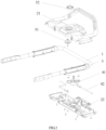
- the embodiment of the present invention discloses the control panel.
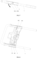
- the control panel comprises the push rod 1 connected to a machine body, the panel assembly 2 reciprocatingly sliding along the push rod 1 and the lock assemblies connected to the panel assembly 2.
- the lock assemblies can either lock the panel assembly 2 on the push rod 1, or unlock the panel assembly 2 from the push rod 1.
- the panel assembly 2 comprises an upper panel 21 and a lower panel 22 connected to the upper panel 21.
- the push rod 1 can be a U-shaped push rod.
- the push rod 1 are usually provided with guideways 3 at opposite sides thereof with the panel assembly 2 reciprocatingly sliding on the guideways 3.
- the lock assemblies comprises a lock knob 41 connected to the panel assembly 2, and at least one lock shaft 42 connected to the lock knob 41 and clamped with the push rod 1.
- the panel assembly 2 When the lock shaft 42 enters into the push rod 1, the panel assembly 2 will be locked on the push rod 1. At this time, the device in which the control panel is disposed, can only work in the manual-power driving mode. When the lock shaft 42 exits from the push rod 1, the panel assembly 2 can automatically slide along the push rod 1, that is, the panel assembly 2 is unlocked. At this time, the device in which the control panel is disposed, can work in self-propelled driving mode.
- the lock shafts 42 can be arranged on two sides of the lock knob 41.
- a plurality of push rod holes can be arranged at the corresponding positions of the guideways 3.
- the lock shafts 42 can lock the panel assembly 2 in different positions of the push rod 1 by inserting in the corresponding push rod holes of the push rod 1.
- the panel assembly 2 comprises a first switch unit connected with the lock knob 41.
- the first switch unit is adapted to control the lock shaft 42 to lock or unlock the panel assembly 2 through the lock knob 41.
- the first motor for providing the self-propelled power for the device with the control panel is closed.
- the first switch unit controls the lock shaft 42 to unlock the panel assembly 2 through the lock knob 41 the first motor for providing the self-propelled power for the device with the control panel is started, and the device can work in self-propelled driving mode.
- the first switch unit is configured to prevent the panel assembly 2 from unlocking or locking by mistake.
- the accident caused by unlocking or locking the panel assembly 2 through directly operating the lock knob 41 can be avoided.
- the safety of the equipment is improved consequently.
- the first switch unit comprises a self-propelled key 51 connected with the lock knob 41.
- the self-propelled key 51 is clamped with the lock knob 41, and the lock knob 41 is driven to rotate by rotating the self-propelled key 51, thereby enabling the lock shaft 42 to unlock the panel assembly 2 through exiting from the push rod 1.
- a buckle body (not shown) is assembled on the self-propelled key 51.
- a buckle slot 52 engaged with the buckle body is arranged on the lock knob 41.
- the lock knob 41 can be driven to rotate by continually rotating the self-propelled key 51.
- both of the cross sections of the buckle body and the buckle slot 52 can be cross-shaped, or zigzag, or star-shaped. That is, no limitation on the cross-sectional shape is required.
- the first switch unit can further comprise a positioning assembly connected with the self-propelled key 51.
- the positioning assembly is adapted to fix the self-propelled key 51.
- the positioning assembly comprises a number of positioning holes 53 arranged on the panel assembly 2 and a number of location columns (not shown) arranged on the self-propelled key 51.
- the location columns are received within the positioning holes 53.
- the self-propelled key 51 is fixed by the engagement between the location columns and the positioning holes 53.
- the quantity of the positioning holes 53 and the location columns are not restricted.
- the quantity of the location columns can be four, and the quantity of the location columns can be two.
- the first switch unit can further comprise a self-propelled key knob 54 assembled on the self-propelled key 51.
- the self-propelled key 51 is driven to move up and down by the self-propelled key knob 54.
- the first switch unit can further comprise a key reset spring 55 sleeved on the self-propelled key knob 54.
- the key reset spring 55 is adapted to reset the location of the self-propelled key 51.
- the self-propelled key 51 can be driven to move downwards to thereby separating from the positioning holes 53 by pressing down the self-propelled key knob 54.
- the buckle body, on the bottom of the self-propelled key 51 can be driven to clamp in the buckle slot 52 of the lock knob 41 by rotating the self-propelled key knob 54.
- the self-propelled key 51 is driven to rotate by continually rotating the self-propelled key knob 54, with the self-propelled key knob 54 rotating and with the left/right lock shafts 42, which connect with the self-propelled key knob 54, driven to compress and separate from the push rod 1 under the rotation of the self-propelled key knob 54.
- the panel assembly 3 is unlocked and can freely slide on the push rod 1.
- the self-propelled key 51 After releasing the self-propelled key knob 54, the self-propelled key 51 is ejected from the lock knob 41 under the action of the key reset spring 55. The self-propelled key 51 is inserted into the corresponding positioning holes 53 of the self-propelled key 51 through the positioning columns, then the device enters in the manual-power driving mode.
- the lock knob 41 can be arranged on the lower panel 22.
- the self-propelled key knob 54 and the self-propelled key 51 can be arranged on the upper panel 21.
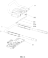
- FIG.1 and FIGS.7-10 another embodiment of the present invention discloses the control panel comprising the panel assembly 2 and a starting switch 71 arranged on the panel assembly 2.
- the starting switch 71 is adapted to open or close the second motor provided power for the device in which the control panel is disposed.
- a first starting unit is disposed on the panel assembly 2, which comprises a starting key 72 disposed on the panel assembly 2 and being moveable up and down, and a pull rod 73 movably connected to the panel assembly 2.
- the starting key 72 moves to a bottom of the panel assembly 2
- the bottom of the starting key 72 will touch and start the starting switch 71 under a push of the bottom of the pull rod 73.
- the starting switch 71 will be closed when the bottom of the starting key 72 is disconnected from the starting switch 71.
- the first starting unit is arranged to avoid the accident caused by starting or closing the second motor through operating the starting switch 71 by mistake, and the safety of the device can be further improved.
- the device can be a lawn mower, in which the control panel is disposed.
- the second motor can be a motor driving the cutter of the lawn mower to rotate.
- the second motor can be a motor driving the impeller of the snow sweeper to rotate.
- the pull rod 73 comprises a compression block 731 adapted for pushing the starting key 72 to touch the starting switch 71 as the pull rod 73 rotating.
- a distance between the starting switch 71 and the compression block 731 is larger than a displacement distance of the compression block 731 caused by the rotation thereof.
- the starting key 72 comprises a movable contact block 721 in contact with the starting switch 71 pushed by the compression block 731.
- One end of the movable contact block 721 is movably connected to the starting key 72, and the other end is in a suspended form.
- the movable contact block 721 is pushed by the compression block 731 to contact the starting switch 71, thereby starting the starting switch 71.
- the movable contact block 721 can be movably connected to the starting key 72 through an elastic connector 74.
- the elastic connector 74 can be a metal dome, or a spring.
- the starting key 72 can pass through the upper panel of the panel assembly 2 and be disposed on the lower panel of the panel assembly 2. Both the pull rod 73 and the starting switch 71 can be assembled onto the lower panel of the panel assembly 2.
- the starting switch 71 can be opened or closed by inserting the starting key 72 into the panel assembly 2. No limitation is required here.
- the starting switch 71 When the starting key 72 is pulled out from the panel assembly 2 or is not pressed, the starting switch 71 will not be touched if operating the pull rod 73, since the compression block 731 of the pull rod 73 cannot contact with the movable contact block 721.
- the compression block 731of the pull rod 73 can be in contact with the movable contact block 721 if operating the pull rod 73. Then, the movable contact block 721 can touch the starting switch 71 to thereby staring the starting switch 71, under the effect of the compression block 731 of the pull rod 73.
- the embodiment of the present invention discloses an automatic switching device comprising a push rod 1 connected to a machine body and a panel assembly 2 reciprocatingly sliding on the push rod 1.
- a motor rotation switch 81 is arranged in the panel assembly 2 and adapted for opening or closing the second motor provided power for the device.
- a second starting unit is disposed on the panel assembly 2.
- the second starting unit can comprise a button unit 82, a connecting assembly 83, and an operating assembly 84, wherein:
- the button unit 82 moves downwards to press the connecting assembly 83 to connect with the operating assembly 84.
- the connecting assembly 83 is driven to move and press on the motor rotation switch 81 by moving the operating assembly 84, so that the motor rotation switch 81 is triggered.
- the second starting unit is configured to avoid the accident caused by starting or closing the second motor through operating the motor rotation switch 81 by mistake, and the safety of the device can be further improved.
- the operating assembly 84 comprises a pull rod 73 movably connected to the panel assembly 2 and a pulling plate 841 driven by the pull rod 73.
- the button unit 82 comprises a pressing head 821 suitable for a pressing operation exerted thereon.
- the connecting assembly 83 comprises a sliding plate 831 movably connected with the panel assembly 2 and a hanging plate 832 movably connected with the sliding plate 831.
- the pressing head 821 is arranged on the upper part of the hanging plate 832, one end of the hanging plate 832 is located on the upper part of the pulling plate 841.
- the pressing head 821 is pressed down to engage the hanging plate 832 and the pulling plate 841.
- the hanging plate 832 is driven to move by moving the pulling plate 841 driven by the pull rod 73, and the sliding plate 831 is driven to move along the panel assembly 2 to trigger the motor rotation switch 81 through the hanging plate 832.
- the pull rod 73 is connected with the pulling plate 841.
- the pulling plate 841 is driven to move on the panel assembly 2 through translating the pull rod 73 on the panel assembly 2.
- the pull rod 73 can be connected to the pulling plate 841 in a variety of ways.
- the end of the pull rod 73 connected with the pulling plate 841 can be arranged with a gear 732, and the end of the pulling plate 841 connected with the pull rod 73 can be arranged with a rack 841a engaged with the gear 732.
- the pulling plate 841 can be driven to move by turning the pull rod 73 with the cooperation of the gear 732 and rack 841a.
- the hanging plate 832 can be clamped with the pulling plate 841 in a variety of ways.
- a clamping groove 841b can be arranged on the pulling plate 841.
- One end of the hanging plate 832 is hinged on the sliding plate 831, and the other end of the hanging plate 832 is provided with a convex structure 832a clamped to the clamping groove 841b.
- the clamping groove 841b on the pulling plate 841 can be driven to engage with the convex structure 832a on the hanging plate 832, thereby making the hanging plate 832 clamped with the pulling plate 841.
- a pressing head button 821a can be arranged and connected at the upper end of the pressing head 821.
- the pressing head 821 can be driven to move downwards by pressing the pressing head button 821a.
- the button unit 82 can be further comprise a button reset spring 822 arranged between the pressing head 821 and the pressing head button 821a.
- the button reset spring 822 is arranged to reset the location of the pressing head button 821a.
- the operating assembly 84 can be further comprise a pulling plate reset spring 842 arranged between the pulling plate 841 and the panel assembly 2.
- the pulling plate reset spring 842 is provided to reset the location of the pulling plate 841.
- the connecting assembly 83 can be further comprise a hanging plate torsion spring 833 connected with the hanging plate 832.
- the hanging plate torsion spring 833 is arranged to reset the location of the hanging plate 832.
- the button unit 82 can be arranged on the upper panel 21 of the panel assembly 2.
- the connecting assembly 83 and the motor rotation switch 81 can be arranged on the lower panel 22 of the panel assembly 2.
- the automatic switching device can be arranged on the control panel.
- the automatic switching device can also serve as a control panel in another embodiment.
- control panel can just integrate the lock assemblies with the first switch unit, or just integrate the starting switch 71 with the first starting unit, or just integrate the motor rotation switch 81 with the second starting unit.
- control panel can integrate any two of or all of the components in above embodiments. That is, no limitation is required.
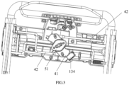
- an embodiment of the present invention also discloses a power device 13.
- the power device 13 comprises a housing 131, a first motor 132 and a second motor 133 located in the housing 131, and a control panel.
- the first motor 132 is adapted to provide self-propelled power
- the second motor 133 is adapted to provide working power for the power device 13.
- the control panel comprises a push rod 1 extending outward from the inner of the housing 131, and a guideway 3 fixed on the push rod 1, and a panel assembly 2 sliding along the guideway 3.
- the control panel further comprises lock assemblies connected to the panel assembly 2. They are adapted to lock or unlock the panel assembly 2 on the push rod 1, so that the power device 13 is switched between a manual-power driving mode and a self-propelled driving mode.
- the power device 13 further comprises a self-propelled switch 134.
- the self-propelled switch 134 is electrically connected with the lock assemblies and the first motor 132, and it is adapted to start or close the first motor.
- the power device 13 can be in a self-propelled driving mode by operating the self-propelled switch 134.
- the lock assemblies are also adapted to fix the self-propelled speed of the power device 13 at different values, so that the power device 13 can be switched in the variable speed self-propelled driving mode and the constant speed self-propelled driving mode to further improve the user experience.
- the lock assemblies are configured to fix the self-propelling speed of the power device 13 at different values, and the lock assemblies can be in several different structures.
- the self-propelling speed of the power device 13 can be fixed at different values by fixing the panel assembly 2 at different positions onto the push rod 1.
- a number of positioning holes can be arranged at different positions of the push rod 1, and the lock assemblies can lock the panel assembly 2 at different positioning holes, in such a manner that fixed the self-propelling speed of the power device 13 at different values.
- the lock assemblies comprise a lock knob 41 connected to the panel assembly 2, and at least one lock shaft 42 connected to the lock knob 41 and clamped with the push rod 1.
- the panel assembly 2 When the lock shaft 42 enters into the push rod 1, the panel assembly 2 is locked on the push rod 1. When the lock shaft 42 exits from the push rod, the panel assembly 2 can automatically slide along the push rod 1. That is, the panel assembly 2 is unlocked.
- the lock knob 41 of the power device 13 can be arranged in conjunction with the self-propelled switch 134, that is, the on-off of the self-propelled switch 134 can be controlled by the rotation of the lock knob 41.
- the operator can operate the self-propelled key 51 by turning the self-propelled key knob 54.
- the lock knob 41 is driven to rotate by the rotation of the self-propelled key 51 and touch the self-propelled switch 134.
- the power device 13 can switch between a variable speed self-propelled driving mode and a constant speed self-propelled driving mode by operating the lock knob 41.
- the power device 13 when the panel assembly 2 is locked at a certain position of the push rod 1, the power device 13 operates in a constant speed self-propelled driving mode. When the panel assembly 2 is not locked onto the push rod 1, the power device 13 operates in a variable speed self-propelled driving mode.
- the paces of the triggering of the self-propelled switch 134 and the unlocking of the lock shaft 42 can be synchronized or not. That is, no limitation is required. Taking the triggering of the self-propelled switch 134 and unlocking of the lock shaft 42 be synchronized as an example, while the lock knob 41 touches the self-propelled switch 134, the lock shaft 42 connected with the lock knob 41 can be unlocked from the push rod 1. At this moment, the control panel can slide along the handle. When the self-propelled switch 134 is closed, the first motor 132 is in standby state, and the rotating speed of the first motor 132 is zero.
- the lock knob 41 and the self-propelled switch 134 of the power device 13 can also be non-linkage setting.
- a separate external switch can be arranged to start or close the self-propelled switch 134, or the self-propelled switch 134 can be directly operated. At this time, the rotating and closing of the lock knob 41 do not affect the on-off of the self-propelled switch 134.
- the self-propelled speed range of the power device 13 can be within [0, 3.5km/s].
- lock knob 41 and the lock shaft 42 can be implemented with reference to the description of the lock assemblies in the above embodiment of the control panel. It will not be described in detail here.
- the panel assembly 2 comprises a first switch unit connected to the lock knob 41.
- the first switch unit is adapted to control the lock shaft 42 locking or unlocking of the panel assembly 2 through operating the lock knob 41.
- the first switch unit comprises a self-propelled key 51 connected to the lock knob 41.
- the self-propelled key 51 is clamped with the lock knob 41, and the lock knob 41 is driven to rotate by rotating the self-propelled key 51.
- the self-propelled key 51 can be implemented with reference to the description of the first switch unit in the above embodiment of the control panel. It will not be described in detail here.
- the panel assembly 2 comprises a starting switch 71 being adapted to start or close the second motor 133 and a first starting unit.
- the first starting unit comprises a starting key 72 disposed on the panel assembly 2 and being moveable up and down, and a pull rod 73 movably connected to the panel assembly 2.
- the bottom of the starting key 72 will touch and start the starting switch 71 under a push of the bottom of the pull rod 73, and the starting switch 71 will be closed when the bottom of the starting key 72 is disconnected from the starting switch 71.
- the pull rod 73 comprises a compression block 731 being adapted to push the starting key 72 to touch the starting switch 71 as the pull rod 73 rotating.
- a distance between the starting switch 71 and the compression block 731 is larger than the displacement distance of the compression block 731 caused by the rotation thereof.
- the starting key 72 and the pull rod 73 can be implemented with reference to the description of the first starting unit in the above embodiment of the control panel. It will not be described in detail here.
- the panel assembly 2 comprises a motor rotation switch 81 arranged in the panel assembly 2.
- the motor rotation switch 81 is adapted to start or close the first motor.
- a second starting unit is disposed on the panel assembly 2.
- the second starting unit comprises a button unit 82, a connecting assembly 83, and an operating assembly 84, wherein the button unit 82 moves downwards to press the connecting assembly 83 to make the connecting assembly 83 connected with the operating assembly 84.
- the connecting assembly 83 is driven to move and press on the motor rotation switch 81 by moving the operating assembly 84, in such a manner that the motor rotation switch 81 is triggered.
- the button unit 82, the connecting assembly 83, and the operating assembly 84 can be implemented with reference to the description of the second starting unit in the above embodiment of the automatic switching device. It will not be described in detail here.
- the panel assembly 2 comprises a sliding potentiometer 9 connected to the first motor 132.
- the sliding potentiometer 9 comprises a potentiometer base 91 and a sliding needle 92 movably connected to the potentiometer base 91. According to the moving distance of the sliding needle 92 on the potentiometer base 91, the rotation speed of the first motor 132 is changed to adjust the self-propelling speed of the power device 13.
- the relative displacement distance between the panel assembly 2 and the guideway 3 is represented by S1 as the preset first distance
- the relative displacement distance between the panel assembly 2 and the guideway 3 is represented by S2 as the maximum distance.
- the acceleration of the sliding needle 92 as moving within the front adjusting distance is less than the acceleration of the sliding needle 92 as moving within the rear adjusting distance, in such a manner that avoiding the power device 13 moving too fast to cause danger as moving within the front adjusting distance.
- the safety can be further improved.
- the potentiometer base 91 can be fixed on the panel assembly 2, and one end of the sliding needle 92 can be fixed on the guideway 3.
- the potentiometer base 91 can be fixed on the guideway 3, and one end of the sliding needle 92 is fixed on the panel assembly 2.
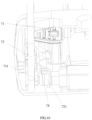
- the panel assembly 2 also can comprise a reset apparatus arranged between the two guideways 3 on both sides of the push rod 1, and the reset apparatus is adapted to reset the location of the panel assembly 2.
- the reset apparatus comprises a reset rod 101 connected with the panel assembly 2 and the push rod 1, and a reset rod return spring 102 sleeved on the reset rod 101.
- One end of the reset rod return spring 102 is connected with the push rod 1.
- the reset rod 101 is driven to rotate around the push rod 1 by the movement of the panel assembly 2, and the reset rod 101 is driven to rotate back by the reset rod return spring 102, in such a manner that the panel assembly 2 moves back to its original position.
- the reset rod 101 comprises a main rod 101a connected with the panel assembly 2 and a pair of auxiliary rods 101b arranged at both ends of the main rod 101a.
- the auxiliary rods 101 are connected with the push rod 1.
- the auxiliary rod 101b can be movably connected to the mounting hole in the push rod 1 and can rotate around the mounting hole.
- the main rod 101a can be clamped with the panel assembly 2.
- the reset rod 101 actively rotates around the push rod 1, and the reset rod 101 is drive to rotate back by the reset rod return spring 102, in such a manner that driving the panel assembly 2 move back to its original position.
- the main rod 101a and the auxiliary rod 101b can be integrated into one.
- the main rod 101a can be cylindrical, and the cross section of the auxiliary rod 101b can be L-shaped.
- both ends of the upper panel 21 and the lower panel 22 of the panel assembly 2 can be movably connected to the guideway 3.
- a chuck 103 can be arranged on the lower panel 22 of the panel assembly 2, and the reset rod 101 can be partially fitted and installed in the chuck 103.
- a chuck 103 can be arranged on the upper panel 21 of the panel assembly 2, and the reset rod 101 can be partially fitted and installed in the chuck 103.
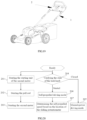
- the power device 13 can be garden tools.
- the garden tool can be a lawn mower as shown in FIG. 16 , or a snow sweeper, a soil loosener, a lawn harrower or any other kinds of wheeled driving device.
- the lawn mower usually comprises a first motor for providing self-propelled power and a second motor for providing the working power for the equipment.
- the first motor and the second motor are usually driven independently.
- the driving process of the second motor is described as follows:
- Step 201 start the starting unit of the second motor.
- the starting unit of the second motor can be the first starting unit in the above-mentioned embodiment, or it can be the second starting unit in the above-mentioned embodiment. That is, no limitation is required.
- the hanging plate can be operated to clamp with the pulling plate by pressing the button assembly, in such a manner that starting the starting unit of the second motor.
- Step 202 start the pull rod.
- the motor rotation switch can be triggered by starting the pull rod and then the sliding plate is driven to move on the panel assembly by the hanging plate driven by the pulling plate.
- Step 203 start the second motor.
- the second motor can be triggered to start working by operating the motor rotation switch. As the second motor is started, the lawn mower can perform mowing work.
- the driving mode of the lawn mower can be determined.
- the lawn mower that the second motor has started either work in manual-power driving mode, or work in constant speed self-propelled driving mode or in variable speed self-propelled driving mode.
- the driving process of the first motor is described as follows:
- Step 204 verify the state of the lock knob.
- step 205 If the lock knob is not turned on, execute step 205, otherwise step 206 is executed.
- Step 205 the lawn mower works under the manual-power driving mode.
- the self-propelled safety is not turned on.
- the self-propelled key knob points to the right 45° in front of the panel assembly, and the lock shafts on the left and right are inserted into the holes of the push rod. At this moment, the whole panel assembly cannot slide along the push rod.
- the first motor is in the closed state. And the lawn mower works in the manual-power driving mode.
- Step 206 the lawn mower works under the self-propelled driving mode.
- the self-propelled key can be driven to separate from the positioning holes by the operator pressing down the self-propelled key knob.
- the buckle body on the bottom of the self-propelled key can be driven to engage in the buckle slot of the lock knob by rotating the self-propelled key knob.
- the self-propelled key is driven to rotate by continually rotating of the self-propelled key knob, in such a manner that the self-propelled key knob is rotating, the lock shafts connected with the self-propelled key knob are driven to compress and separate from the push rod by rotating the self-propelled key knob.
- the panel assembly is unlocked and can freely slide on the push rod.
- the self-propelled key When releasing the self-propelled key knob, the self-propelled key is ejected from the lock knob under the action of the key reset spring. The self-propelled key is inserted into the corresponding positioning holes of the self-propelled key through the positioning columns, and enters in the self-propelled driving mode.
- Step 207 determine the self-propelled speed based on the location of the sliding potentiometer.
- the panel assembly is driven to slide forward along the guideway on the push rod through the operator pushing the panel assembly, in such a manner that, the reset rod being driven to rotate forward by the sliding of the panel assembly.
- the reset rod will rotate backward under the action of torsional spring force. At this moment, the reset rod the panel assembly can be driven to slide backward along the guideway to the original position.
- the sliding needle of the sliding potentiometer When the panel assembly moves on the guideway, the sliding needle of the sliding potentiometer is driven to slide on the potentiometer base by the movement of the panel assembly, and producing relative displacement. According to the moving distance of the sliding needle on the potentiometer base, the first motor determines the self-propelled speed of the lawn mower. The larger the moving distance of the panel assembly on the guideway, the larger the stroke of the sliding potentiometer, and the faster the self-propelled speed of the lawn mower.
- the panel assembly is reset. Then the left lock shaft on the lock knob is inserted into the push rod by turning the self-propelled key. Then the self-propelled key returns to its original position by releasing the self-propelled key knob. The first motor is closed.
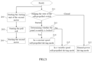
- the driving process of the first motor is described as follows:
- Step 211 judge the self-propelled switch state.
- step 212 is executed. Otherwise, step 213 is executed.
- Step 212 the lawn mower works under the manual-power driving mode.
- Step 213 determine whether the panel assembly is locked.
- the sliding needle of the sliding potentiometer When the panel assembly moves on the guideway, the sliding needle of the sliding potentiometer is driven to slide on the potentiometer base by the movement of the panel assembly, and producing relative displacement. According to the moving distance of the sliding needle on the potentiometer base, the first motor determines the self-propelled speed of the lawn mower. The larger the moving distance of the panel assembly on the guideway, the larger the stroke of the sliding potentiometer, and the faster the self-propelled speed of the lawn mower.
- step 214 is executed. Otherwise, step 215 is executed.
- Step 214 the lawn mower is in a constant speed self-propelled driving mode.
- the self-propelled speed can be determined. And in such a manner that the device working in constant speed self-propelled driving mode.
- Step 215 the lawn mower is in a variable speed self-propelled driving mode.
- the lawn mower When the panel assembly is unlocked, the lawn mower is in a variable speed self-propelled driving mode.
- the self-propelled switch can be used to unlock the panel assembly and put the panel assembly back to its original position. At this moment, the pull rod is loosened, and the starting unit of the second motor is closed. And the lawn mower stops working.
- control panel and the power device of the invention can be switched among various driving modes, and it is convenient for the operator to operate.
- the control panel can also be used on other kinds of wheeled driving device, such as snow sweepers and soil looseners.
- the principle of the power devices is also within the scope of the protection of this patent, and the detail will not be described here.
Applications Claiming Priority (6)
| Application Number | Priority Date | Filing Date | Title |
|---|---|---|---|
| CN201610412240.1A CN106057553B (zh) | 2016-06-14 | 2016-06-14 | 控制面板及使用该面板的园林工具 |
| CN201610419586.4A CN106105541B (zh) | 2016-06-14 | 2016-06-14 | 自走开关装置及其推草机 |
| CN201610413596.7A CN106034568B (zh) | 2016-06-14 | 2016-06-14 | 动力设备及控制方法 |
| CN201610412321.1A CN106063409B (zh) | 2016-06-14 | 2016-06-14 | 控制面板及其推草机 |
| PCT/CN2017/088216 WO2017215604A1 (fr) | 2016-06-14 | 2017-06-14 | Panneau de commande, appareil de commutation automoteur et dispositif d'alimentation |
| EP17812715.5A EP3471126B1 (fr) | 2016-06-14 | 2017-06-14 | Dispositif d'alimentation |
Related Parent Applications (3)
| Application Number | Title | Priority Date | Filing Date |
|---|---|---|---|
| EP17812715.5A Division-Into EP3471126B1 (fr) | 2016-06-14 | 2017-06-14 | Dispositif d'alimentation |
| EP17812715.5A Division EP3471126B1 (fr) | 2016-06-14 | 2017-06-14 | Dispositif d'alimentation |
| PCT/CN2017/088216 Previously-Filed-Application WO2017215604A1 (fr) | 2016-06-14 | 2017-06-14 | Panneau de commande, appareil de commutation automoteur et dispositif d'alimentation |
Publications (2)
| Publication Number | Publication Date |
|---|---|
| EP4324322A2 true EP4324322A2 (fr) | 2024-02-21 |
| EP4324322A3 EP4324322A3 (fr) | 2024-02-28 |
Family
ID=60663965
Family Applications (2)
| Application Number | Title | Priority Date | Filing Date |
|---|---|---|---|
| EP17812715.5A Active EP3471126B1 (fr) | 2016-06-14 | 2017-06-14 | Dispositif d'alimentation |
| EP23185300.3A Pending EP4324322A3 (fr) | 2016-06-14 | 2017-06-14 | Panneau de commande, appareil de commutation autopropulsé et dispositif d'alimentation |
Family Applications Before (1)
| Application Number | Title | Priority Date | Filing Date |
|---|---|---|---|
| EP17812715.5A Active EP3471126B1 (fr) | 2016-06-14 | 2017-06-14 | Dispositif d'alimentation |
Country Status (4)
| Country | Link |
|---|---|
| US (1) | US11272658B2 (fr) |
| EP (2) | EP3471126B1 (fr) |
| ES (1) | ES2962769T3 (fr) |
| WO (1) | WO2017215604A1 (fr) |
Families Citing this family (12)
| Publication number | Priority date | Publication date | Assignee | Title |
|---|---|---|---|---|
| JP2018088833A (ja) * | 2016-11-30 | 2018-06-14 | 本田技研工業株式会社 | 電動式作業機 |
| US10709064B2 (en) * | 2018-01-31 | 2020-07-14 | The Toro Company | Propulsion control lockout and ground working vehicle incorporating same |
| WO2020033522A2 (fr) | 2018-08-08 | 2020-02-13 | The Toro Company | Poignée et procédé d'entraînement d'un véhicule autonome, et ses procédés de rangement |
| US11051450B2 (en) * | 2018-11-09 | 2021-07-06 | The Toro Company | Walk reel mower with a telescopic handle assembly |
| CN109392467B (zh) * | 2018-12-14 | 2024-01-02 | 格力博(江苏)股份有限公司 | 园林工具 |
| MX2020000519A (es) * | 2019-01-31 | 2020-08-20 | Techtronic Cordless Gp | Herramienta electrica que tiene altura o velocidad variable. |
| CN214413506U (zh) | 2019-07-25 | 2021-10-19 | 南京德朔实业有限公司 | 后走式自推工作机 |
| CN111937585A (zh) * | 2020-09-11 | 2020-11-17 | 广西师范大学 | 一种用于桑叶自动采摘机的桑枝拨动定位装置 |
| EP4129041A4 (fr) * | 2021-04-27 | 2023-11-29 | Nanjing Chervon Industry Co., Ltd. | Machine de travail poussée autopropulsée |
| CN113924865B (zh) * | 2021-08-24 | 2023-05-02 | 江苏东成工具科技有限公司 | 园林工具 |
| US20230098509A1 (en) * | 2021-09-29 | 2023-03-30 | The Toro Company | Walk outdoor power equipment unit having handle mounted operational controls using compliant mechanisms |
| CN114365616A (zh) * | 2021-12-30 | 2022-04-19 | 江苏东成工具科技有限公司 | 手推式电动工具 |
Family Cites Families (39)
| Publication number | Priority date | Publication date | Assignee | Title |
|---|---|---|---|---|
| US3218876A (en) * | 1963-07-15 | 1965-11-23 | Hoover Co | Variable speed power propelled appliances |
| EP0047416B2 (fr) * | 1980-09-04 | 1988-07-27 | Wolf-Geräte GmbH | Dispositif d'interrupteur de sécurité pour une tondeuse à gazon électrique |
| US5203147A (en) * | 1992-01-22 | 1993-04-20 | Ryobi Motor Products Corp. | Lawn mower activation switch |
| US5442901A (en) * | 1994-07-22 | 1995-08-22 | Ryobi North America | Self-propelled mower |
| US6082083A (en) * | 1998-09-18 | 2000-07-04 | The Toro Company | Ground speed control system |
| FR2790434B1 (fr) * | 1999-03-04 | 2002-08-02 | Honda Motor Co Ltd | Vehicule de transport manuel a moteur |
| US6644002B2 (en) * | 2001-09-25 | 2003-11-11 | Deere & Company | Walk-behind self-propelled power equipment unit with speed control |
| US7165383B1 (en) | 2003-06-24 | 2007-01-23 | Luton Jr James J | Trimmer attachment for mower deck |
| DE102004007162A1 (de) * | 2004-02-12 | 2005-08-25 | Sabo - Maschinenfabrik Gmbh | Gerät zur Rasen-, Garten- und Grundstückspflege |
| US7178322B2 (en) * | 2004-06-17 | 2007-02-20 | Honda Motor Co. Ltd. | Apparatuses and methods for controlling self-propelled machines |
| US7540131B2 (en) * | 2004-09-16 | 2009-06-02 | The Toro Company | Ground speed control system with hill assist, cruise control and lockout lever |
| US7540102B2 (en) * | 2005-03-02 | 2009-06-02 | Wisconsin Engineering, Cz S.R.O. | Snow blower apparatus |
| US7712292B2 (en) * | 2005-11-09 | 2010-05-11 | The Toro Company | Control system for outdoor power equipment |
| JP4925723B2 (ja) | 2006-05-24 | 2012-05-09 | 本田技研工業株式会社 | 芝刈機の駆動操作機構 |
| CN101147452B (zh) * | 2006-09-21 | 2011-09-07 | 苏州宝时得电动工具有限公司 | 割草机 |
| GB0622148D0 (en) * | 2006-11-07 | 2006-12-20 | Arpino Mario P | Walk-with apparatus |
| JP4392017B2 (ja) * | 2006-11-28 | 2009-12-24 | 本田技研工業株式会社 | 作業機 |
| US7698881B2 (en) * | 2008-09-12 | 2010-04-20 | Briggs And Stratton Corporation | Walk-behind mower control system and method |
| US7762049B2 (en) * | 2008-12-31 | 2010-07-27 | Black & Decker Inc. | Electric mower having two-motion activation system |
| TWM380528U (en) * | 2009-08-13 | 2010-05-11 | Wistron Corp | Button locking mechanism for preventing a button from being pressed down and electronic device thereof |
| WO2011131031A1 (fr) * | 2010-04-21 | 2011-10-27 | 苏州宝时得电动工具有限公司 | Tondeuse à gazon et procédé de commande pour commander son fonctionnement à entraînement automatique |
| US9651138B2 (en) | 2011-09-30 | 2017-05-16 | Mtd Products Inc. | Speed control assembly for a self-propelled walk-behind lawn mower |
| JP2013099324A (ja) | 2011-10-12 | 2013-05-23 | Chikusui Canycom Inc | 歩行型草刈り機 |
| US20130312566A1 (en) * | 2012-05-25 | 2013-11-28 | Chadwick A. Shaffer | Implement and operator control for use with same |
| US20140102068A1 (en) * | 2012-10-12 | 2014-04-17 | Honda Motor Co., Ltd. | Speed control device for lawnmower |
| CN102845186B (zh) * | 2012-10-15 | 2015-11-25 | 南京德朔实业有限公司 | 具有操作保护的割草机及其安全开关机构 |
| US9847186B2 (en) * | 2013-01-30 | 2017-12-19 | The Toro Company | Starter and power equipment unit incorporating same |
| US9696749B2 (en) * | 2013-05-24 | 2017-07-04 | Honda Motor Co., Ltd. | Control devices, systems, and methods for self-propelled machinery |
| CN104686049B (zh) | 2013-12-04 | 2017-09-22 | 苏州宝时得电动工具有限公司 | 割草机 |
| JP6278828B2 (ja) * | 2014-05-14 | 2018-02-14 | 株式会社ユーシン | 車両用アクチュエータ |
| CN105432238B (zh) | 2014-08-21 | 2017-06-30 | 南京德朔实业有限公司 | 割草机及其安全装置 |
| US9403435B2 (en) | 2014-10-14 | 2016-08-02 | Honda Motor Co., Ltd. | Adjustable ground speed control devices, systems, and methods for walk-behind equipment |
| US9545054B2 (en) * | 2014-10-22 | 2017-01-17 | Honda Motor Co., Ltd. | Mechanisms and related methods for drive by wire control systems in walk-behind working machines |
| CN204616397U (zh) | 2015-01-15 | 2015-09-09 | 苏州宝时得电动工具有限公司 | 割草机 |
| CN105325128B (zh) | 2015-11-28 | 2017-06-09 | 宁波市德霖机械有限公司 | 一种割草机的操作机构及其割草机 |
| CN106105541B (zh) | 2016-06-14 | 2019-01-18 | 常州格力博有限公司 | 自走开关装置及其推草机 |
| CN106063409B (zh) | 2016-06-14 | 2019-04-02 | 常州格力博有限公司 | 控制面板及其推草机 |
| CN106034568B (zh) | 2016-06-14 | 2018-07-20 | 常州格力博有限公司 | 动力设备及控制方法 |
| CN106057553B (zh) | 2016-06-14 | 2018-12-11 | 常州格力博有限公司 | 控制面板及使用该面板的园林工具 |
-
2017
- 2017-06-14 ES ES17812715T patent/ES2962769T3/es active Active
- 2017-06-14 EP EP17812715.5A patent/EP3471126B1/fr active Active
- 2017-06-14 WO PCT/CN2017/088216 patent/WO2017215604A1/fr unknown
- 2017-06-14 EP EP23185300.3A patent/EP4324322A3/fr active Pending
- 2017-06-14 US US16/309,664 patent/US11272658B2/en active Active
Also Published As
| Publication number | Publication date |
|---|---|
| EP3471126B1 (fr) | 2023-08-16 |
| WO2017215604A1 (fr) | 2017-12-21 |
| ES2962769T3 (es) | 2024-03-21 |
| US11272658B2 (en) | 2022-03-15 |
| EP3471126A4 (fr) | 2020-06-03 |
| EP4324322A3 (fr) | 2024-02-28 |
| EP3471126A1 (fr) | 2019-04-17 |
| EP3471126C0 (fr) | 2023-08-16 |
| US20190307066A1 (en) | 2019-10-10 |
Similar Documents
| Publication | Publication Date | Title |
|---|---|---|
| EP4324322A2 (fr) | Panneau de commande, appareil de commutation autopropulsé et dispositif d'alimentation | |
| US11622502B2 (en) | Push rod mechanism for garden tool, garden tool, and method for using garden tool | |
| CN106105541B (zh) | 自走开关装置及其推草机 | |
| EP1747854B1 (fr) | Outil électrique | |
| US20110162218A1 (en) | Hand held circular saw power tool having multiple modes of operation | |
| KR102418863B1 (ko) | 실용적 아트 나이프 | |
| CN1322119A (zh) | 防止搅拌器或食品加工机在杯盖未盖好时运转的安全系统 | |
| CN111983876B (zh) | 一种旋转手柄装置 | |
| EP3031314A1 (fr) | Dispositif de commande pour outils de jardinage | |
| CN109961978B (zh) | 用于电气设备的触发器组件的锁定系统 | |
| CN106057553B (zh) | 控制面板及使用该面板的园林工具 | |
| EP3669628B1 (fr) | Outil de jardin et son boîtier de commande | |
| EP3666055B1 (fr) | Outil de jardin | |
| CN109890251B (zh) | 用于可移动家具部件的推出装置、家具和用于打开可移动家具部件的方法 | |
| CN106034568B (zh) | 动力设备及控制方法 | |
| CN106063409B (zh) | 控制面板及其推草机 | |
| CN110313873A (zh) | 一种智能移动机器人系统及智能移动机器人 | |
| CN205883994U (zh) | 自走开关装置及其推草机 | |
| CN205883996U (zh) | 活动面板结构及其推草机 | |
| WO2017219435A1 (fr) | Dispositif de presse d'emballage mécanique | |
| CN205884036U (zh) | 动力设备 | |
| CN219497575U (zh) | 一种电动工具的电源开关盒以及电动工具 | |
| CN110242102A (zh) | 一种自动伸缩式手柄 | |
| CN220515602U (zh) | 手持往复锯 | |
| CN111321957A (zh) | 油箱充电口盖锁 |
Legal Events
| Date | Code | Title | Description |
|---|---|---|---|
| PUAI | Public reference made under article 153(3) epc to a published international application that has entered the european phase |
Free format text: ORIGINAL CODE: 0009012 |
|
| REG | Reference to a national code |
Ref country code: DE Ref legal event code: R079 Free format text: PREVIOUS MAIN CLASS: A01D0034820000 Ipc: H01H0027060000 |
|
| STAA | Information on the status of an ep patent application or granted ep patent |
Free format text: STATUS: THE APPLICATION HAS BEEN PUBLISHED |
|
| PUAL | Search report despatched |
Free format text: ORIGINAL CODE: 0009013 |
|
| AC | Divisional application: reference to earlier application |
Ref document number: 3471126 Country of ref document: EP Kind code of ref document: P |
|
| AK | Designated contracting states |
Kind code of ref document: A2 Designated state(s): AL AT BE BG CH CY CZ DE DK EE ES FI FR GB GR HR HU IE IS IT LI LT LU LV MC MK MT NL NO PL PT RO RS SE SI SK SM TR |
|
| AK | Designated contracting states |
Kind code of ref document: A3 Designated state(s): AL AT BE BG CH CY CZ DE DK EE ES FI FR GB GR HR HU IE IS IT LI LT LU LV MC MK MT NL NO PL PT RO RS SE SI SK SM TR |
|
| RIC1 | Information provided on ipc code assigned before grant |
Ipc: A01D 34/82 20060101ALI20240119BHEP Ipc: A01D 34/68 20060101ALI20240119BHEP Ipc: A01D 75/00 20060101ALI20240119BHEP Ipc: A01D 34/00 20060101ALI20240119BHEP Ipc: H01H 27/06 20060101AFI20240119BHEP |