EP4321717A1 - Dispositif de sécurité pour une installation automatisée de porte, installation de porte équipée de celui-ci et procédé de fonctionnement d'une telle installation de porte - Google Patents
Dispositif de sécurité pour une installation automatisée de porte, installation de porte équipée de celui-ci et procédé de fonctionnement d'une telle installation de porte Download PDFInfo
- Publication number
- EP4321717A1 EP4321717A1 EP22190293.5A EP22190293A EP4321717A1 EP 4321717 A1 EP4321717 A1 EP 4321717A1 EP 22190293 A EP22190293 A EP 22190293A EP 4321717 A1 EP4321717 A1 EP 4321717A1
- Authority
- EP
- European Patent Office
- Prior art keywords
- door leaf
- door
- detection
- leaf
- speed
- Prior art date
- Legal status (The legal status is an assumption and is not a legal conclusion. Google has not performed a legal analysis and makes no representation as to the accuracy of the status listed.)
- Pending
Links
- 238000011017 operating method Methods 0.000 title abstract description 3
- 238000001514 detection method Methods 0.000 claims abstract description 94
- 238000006243 chemical reaction Methods 0.000 claims abstract description 18
- 238000000034 method Methods 0.000 claims description 28
- 230000008859 change Effects 0.000 claims description 4
- 238000012544 monitoring process Methods 0.000 claims description 4
- 230000003213 activating effect Effects 0.000 claims description 2
- 230000001953 sensory effect Effects 0.000 claims 1
- 230000008569 process Effects 0.000 description 6
- 230000008901 benefit Effects 0.000 description 5
- 238000013459 approach Methods 0.000 description 4
- 230000006378 damage Effects 0.000 description 3
- 241001465754 Metazoa Species 0.000 description 2
- 208000027418 Wounds and injury Diseases 0.000 description 2
- 230000004913 activation Effects 0.000 description 2
- 230000007423 decrease Effects 0.000 description 2
- 238000013461 design Methods 0.000 description 2
- 230000000694 effects Effects 0.000 description 2
- 208000014674 injury Diseases 0.000 description 2
- 238000009434 installation Methods 0.000 description 2
- 238000012360 testing method Methods 0.000 description 2
- 230000001133 acceleration Effects 0.000 description 1
- 230000001419 dependent effect Effects 0.000 description 1
- 238000011161 development Methods 0.000 description 1
- 230000018109 developmental process Effects 0.000 description 1
- 230000002996 emotional effect Effects 0.000 description 1
- 230000002779 inactivation Effects 0.000 description 1
- 230000009467 reduction Effects 0.000 description 1
Images


Classifications
-
- E—FIXED CONSTRUCTIONS
- E05—LOCKS; KEYS; WINDOW OR DOOR FITTINGS; SAFES
- E05F—DEVICES FOR MOVING WINGS INTO OPEN OR CLOSED POSITION; CHECKS FOR WINGS; WING FITTINGS NOT OTHERWISE PROVIDED FOR, CONCERNED WITH THE FUNCTIONING OF THE WING
- E05F15/00—Power-operated mechanisms for wings
- E05F15/40—Safety devices, e.g. detection of obstructions or end positions
- E05F15/42—Detection using safety edges
- E05F15/43—Detection using safety edges responsive to disruption of energy beams, e.g. light or sound
-
- E—FIXED CONSTRUCTIONS
- E05—LOCKS; KEYS; WINDOW OR DOOR FITTINGS; SAFES
- E05F—DEVICES FOR MOVING WINGS INTO OPEN OR CLOSED POSITION; CHECKS FOR WINGS; WING FITTINGS NOT OTHERWISE PROVIDED FOR, CONCERNED WITH THE FUNCTIONING OF THE WING
- E05F15/00—Power-operated mechanisms for wings
- E05F15/40—Safety devices, e.g. detection of obstructions or end positions
- E05F15/42—Detection using safety edges
-
- E—FIXED CONSTRUCTIONS
- E05—LOCKS; KEYS; WINDOW OR DOOR FITTINGS; SAFES
- E05F—DEVICES FOR MOVING WINGS INTO OPEN OR CLOSED POSITION; CHECKS FOR WINGS; WING FITTINGS NOT OTHERWISE PROVIDED FOR, CONCERNED WITH THE FUNCTIONING OF THE WING
- E05F15/00—Power-operated mechanisms for wings
- E05F15/60—Power-operated mechanisms for wings using electrical actuators
- E05F15/603—Power-operated mechanisms for wings using electrical actuators using rotary electromotors
- E05F15/608—Power-operated mechanisms for wings using electrical actuators using rotary electromotors for revolving wings
-
- E—FIXED CONSTRUCTIONS
- E05—LOCKS; KEYS; WINDOW OR DOOR FITTINGS; SAFES
- E05F—DEVICES FOR MOVING WINGS INTO OPEN OR CLOSED POSITION; CHECKS FOR WINGS; WING FITTINGS NOT OTHERWISE PROVIDED FOR, CONCERNED WITH THE FUNCTIONING OF THE WING
- E05F15/00—Power-operated mechanisms for wings
- E05F15/60—Power-operated mechanisms for wings using electrical actuators
- E05F15/603—Power-operated mechanisms for wings using electrical actuators using rotary electromotors
- E05F15/611—Power-operated mechanisms for wings using electrical actuators using rotary electromotors for swinging wings
-
- E—FIXED CONSTRUCTIONS
- E05—LOCKS; KEYS; WINDOW OR DOOR FITTINGS; SAFES
- E05F—DEVICES FOR MOVING WINGS INTO OPEN OR CLOSED POSITION; CHECKS FOR WINGS; WING FITTINGS NOT OTHERWISE PROVIDED FOR, CONCERNED WITH THE FUNCTIONING OF THE WING
- E05F15/00—Power-operated mechanisms for wings
- E05F15/60—Power-operated mechanisms for wings using electrical actuators
- E05F15/603—Power-operated mechanisms for wings using electrical actuators using rotary electromotors
- E05F15/632—Power-operated mechanisms for wings using electrical actuators using rotary electromotors for horizontally-sliding wings
-
- E—FIXED CONSTRUCTIONS
- E05—LOCKS; KEYS; WINDOW OR DOOR FITTINGS; SAFES
- E05F—DEVICES FOR MOVING WINGS INTO OPEN OR CLOSED POSITION; CHECKS FOR WINGS; WING FITTINGS NOT OTHERWISE PROVIDED FOR, CONCERNED WITH THE FUNCTIONING OF THE WING
- E05F15/00—Power-operated mechanisms for wings
- E05F15/40—Safety devices, e.g. detection of obstructions or end positions
- E05F15/42—Detection using safety edges
- E05F15/43—Detection using safety edges responsive to disruption of energy beams, e.g. light or sound
- E05F2015/432—Detection using safety edges responsive to disruption of energy beams, e.g. light or sound with acoustical sensors
- E05F2015/433—Detection using safety edges responsive to disruption of energy beams, e.g. light or sound with acoustical sensors using reflection from the obstruction
-
- E—FIXED CONSTRUCTIONS
- E05—LOCKS; KEYS; WINDOW OR DOOR FITTINGS; SAFES
- E05F—DEVICES FOR MOVING WINGS INTO OPEN OR CLOSED POSITION; CHECKS FOR WINGS; WING FITTINGS NOT OTHERWISE PROVIDED FOR, CONCERNED WITH THE FUNCTIONING OF THE WING
- E05F15/00—Power-operated mechanisms for wings
- E05F15/40—Safety devices, e.g. detection of obstructions or end positions
- E05F15/42—Detection using safety edges
- E05F15/43—Detection using safety edges responsive to disruption of energy beams, e.g. light or sound
- E05F2015/434—Detection using safety edges responsive to disruption of energy beams, e.g. light or sound with optical sensors
-
- E—FIXED CONSTRUCTIONS
- E05—LOCKS; KEYS; WINDOW OR DOOR FITTINGS; SAFES
- E05F—DEVICES FOR MOVING WINGS INTO OPEN OR CLOSED POSITION; CHECKS FOR WINGS; WING FITTINGS NOT OTHERWISE PROVIDED FOR, CONCERNED WITH THE FUNCTIONING OF THE WING
- E05F15/00—Power-operated mechanisms for wings
- E05F15/40—Safety devices, e.g. detection of obstructions or end positions
- E05F15/42—Detection using safety edges
- E05F2015/487—Fault detection of safety edges
-
- E—FIXED CONSTRUCTIONS
- E05—LOCKS; KEYS; WINDOW OR DOOR FITTINGS; SAFES
- E05Y—INDEXING SCHEME RELATING TO HINGES OR OTHER SUSPENSION DEVICES FOR DOORS, WINDOWS OR WINGS AND DEVICES FOR MOVING WINGS INTO OPEN OR CLOSED POSITION, CHECKS FOR WINGS AND WING FITTINGS NOT OTHERWISE PROVIDED FOR, CONCERNED WITH THE FUNCTIONING OF THE WING
- E05Y2201/00—Constructional elements; Accessories therefore
- E05Y2201/20—Brakes; Disengaging means, e.g. clutches; Holders, e.g. locks; Stops; Accessories therefore
- E05Y2201/21—Brakes
-
- E—FIXED CONSTRUCTIONS
- E05—LOCKS; KEYS; WINDOW OR DOOR FITTINGS; SAFES
- E05Y—INDEXING SCHEME RELATING TO HINGES OR OTHER SUSPENSION DEVICES FOR DOORS, WINDOWS OR WINGS AND DEVICES FOR MOVING WINGS INTO OPEN OR CLOSED POSITION, CHECKS FOR WINGS AND WING FITTINGS NOT OTHERWISE PROVIDED FOR, CONCERNED WITH THE FUNCTIONING OF THE WING
- E05Y2201/00—Constructional elements; Accessories therefore
- E05Y2201/20—Brakes; Disengaging means, e.g. clutches; Holders, e.g. locks; Stops; Accessories therefore
- E05Y2201/23—Actuation thereof
- E05Y2201/232—Actuation thereof by automatically acting means
- E05Y2201/242—Actuation thereof by automatically acting means using threshold speed
-
- E—FIXED CONSTRUCTIONS
- E05—LOCKS; KEYS; WINDOW OR DOOR FITTINGS; SAFES
- E05Y—INDEXING SCHEME RELATING TO HINGES OR OTHER SUSPENSION DEVICES FOR DOORS, WINDOWS OR WINGS AND DEVICES FOR MOVING WINGS INTO OPEN OR CLOSED POSITION, CHECKS FOR WINGS AND WING FITTINGS NOT OTHERWISE PROVIDED FOR, CONCERNED WITH THE FUNCTIONING OF THE WING
- E05Y2400/00—Electronic control; Power supply; Power or signal transmission; User interfaces
- E05Y2400/10—Electronic control
- E05Y2400/30—Electronic control of motors
- E05Y2400/36—Speed control, detection or monitoring
-
- E—FIXED CONSTRUCTIONS
- E05—LOCKS; KEYS; WINDOW OR DOOR FITTINGS; SAFES
- E05Y—INDEXING SCHEME RELATING TO HINGES OR OTHER SUSPENSION DEVICES FOR DOORS, WINDOWS OR WINGS AND DEVICES FOR MOVING WINGS INTO OPEN OR CLOSED POSITION, CHECKS FOR WINGS AND WING FITTINGS NOT OTHERWISE PROVIDED FOR, CONCERNED WITH THE FUNCTIONING OF THE WING
- E05Y2400/00—Electronic control; Power supply; Power or signal transmission; User interfaces
- E05Y2400/10—Electronic control
- E05Y2400/52—Safety arrangements
- E05Y2400/53—Wing impact prevention or reduction
- E05Y2400/54—Obstruction or resistance detection
- E05Y2400/56—Obstruction or resistance detection by using speed sensors
-
- E—FIXED CONSTRUCTIONS
- E05—LOCKS; KEYS; WINDOW OR DOOR FITTINGS; SAFES
- E05Y—INDEXING SCHEME RELATING TO HINGES OR OTHER SUSPENSION DEVICES FOR DOORS, WINDOWS OR WINGS AND DEVICES FOR MOVING WINGS INTO OPEN OR CLOSED POSITION, CHECKS FOR WINGS AND WING FITTINGS NOT OTHERWISE PROVIDED FOR, CONCERNED WITH THE FUNCTIONING OF THE WING
- E05Y2900/00—Application of doors, windows, wings or fittings thereof
- E05Y2900/10—Application of doors, windows, wings or fittings thereof for buildings or parts thereof
- E05Y2900/13—Application of doors, windows, wings or fittings thereof for buildings or parts thereof characterised by the type of wing
- E05Y2900/132—Doors
Definitions
- the invention relates to a security device of an automated door system and an automated door system equipped therewith.
- the invention relates to the use of such a safety device in a door drive with at least one drive unit for moving the at least one associated door leaf or in a door system.
- the invention further relates to a method for operating such a door system.
- Generic automated door systems include at least one door leaf that is moved by means of a drive.
- at least its turnstile (with door wings attached to it in a fixed or pivoting manner) is rotated in a predetermined direction of rotation. If the door leaves are mounted so that they can pivot, they can also be pivoted using a respective drive.
- the door leaf(s) is/are automatic, ie by means of an associated drive, in both the opening and closing directions emotional.
- the door leaves cover an associated movement area.
- this is a circular area.
- this is the path along which the respective sliding door leaf is moved.
- this is the partial circle area within which the respective swing leaf is moved.
- the area is always seen in the direction of movement of the respective door leaf.
- Objects such as people, animals and objects can be in the path of movement of a door leaf or move into the path of movement or towards the door leaf or move away from the door leaf more slowly than the door leaf itself moves. This creates dangerous areas that are usually secured without contact by sensors.
- the sensors have a defined detection field that includes the danger areas. If an object is recognized or detected within the detection field, the sensor sends a signal to the associated door drive, and a safety reaction occurs by braking, stopping or reversing the current door leaf movement using the drive.
- the movement speed of the associated door leaf realized by the respective door drive is set manually when the door system is commissioned so that this door leaf can be stopped in good time in the event of danger. It must be noted that the faster and heavier the associated door leaf(s) is, the longer the braking distance is.
- the control of the door drive does not know the position and size of the detection field and can therefore Do not limit driving speed automatically.
- the braking strength for the door leaves of a door system is set uniformly; it is fixed for a specific door leaf movement speed/mass combination. In practice, the detection field of the safety sensors is manually compared with the required braking distance.
- the position of the detection field is adjusted mechanically (manually) by pivoting the sensor device and is therefore only valid for one speed. If the travel or movement speed of the respective door leaf decreases, this can result in object detection occurring too early and the door no longer opens properly. If the driving speed increases, the object may be detected too late and the object will be hit by the door leaf, creating a significant risk of injury. Such a change in travel speed can occur due to wind or manual operation, particularly with revolving and swing doors, and the danger areas are not always secure. With sliding doors, the wind load can also cause the travel speed to decrease. The travel speed set during installation is not changed during operation. In any case, the coordination with the respective sensor detection range is no longer correct. Even if an object in the form of a person or animal approaches the respective door system or one of its danger areas at too high or too low a speed, this can have similar effects as when changing the driving speed.
- the EP 3 026 457 A1 discloses a device for monitoring a detection field, in which a sensor detection field is monitored. However, a deviation of an actual detection field from a target detection field results only for a safety reaction, for example in the form of a warning signal, the detection field remains untouched.
- This task is based on a security device according to the preamble of claim 1, an automated door system according to the preamble of claim 6 and an operating method for such a door system according to the preamble of claim 11 in conjunction with the respective characterizing features.
- Advantageous developments of the invention are specified in the dependent claims.
- a safety device is used in a door drive or in a door system.
- the invention includes the technical teaching that a security device of an automated door system has a sensor device.
- the sensor device with one or more sensors is designed to be arranged on the door system in such a way that its associated detection area sensorily covers a danger area of an associated door leaf. This is, for example, the main closing edge of a door leaf of the door system.
- the sensor device is set up within the associated Detection area to detect the presence of an object.
- the security device has a control device. According to the invention, the control device is set up to change the associated detection area based on a current movement speed of the associated door leaf.
- the detection area is changed in relation to the edge or the side that points in the direction of movement of this door leaf, for example, so that its maximum distance from the The higher the door leaf movement speed, the larger the door leaf becomes.
- the control device is set up to determine a detection geometry and to control a door drive of the associated door leaf in such a way that a predetermined, i.e. a maximum permissible and/or possible, movement speed of the associated door leaf is provided depending on the determined detection geometry becomes.
- the door drive is controlled in such a way that a braking force and/or a braking distance of the associated door leaf is or are adapted to the current movement speed of the associated door leaf.
- a safety reaction i.e. if an object was detected in the movement path of the door leaf
- the invention either adapts the detection area to the door leaf movement speed.
- the detection area preferably remains the same, and the detection geometry and thus the detection distance in relation to the associated door leaf or the door system as a whole are calculated so that the control device can gain knowledge of how quickly the door leaf can actually be moved.
- the control device knows how much the door leaf must be braked when an object appears in the detection area so that this door leaf can still stop safely in front of the object or only hits it with a defined force or final speed that is classified as harmless to the object.
- control device can interact with the sensor device.
- the sensor device can have infrared and/or radar sensors, in particular consist of a radar sensor unit.
- the door leaf movement speed or travel speed is dynamically adjusted depending on the approach speed of an object. This means that people moving faster are no longer slowed down by the door system as much or at all, which improves the comfort of using the door system.
- the said detection range of the sensor device can be changed by the sensor device having an adjusting device which is coupled to the control device in such a way that the control device is able to adjust the sensor device.
- the adjustment is carried out in such a way that the detection area changes.
- its setting angle can be changed by a motor.
- the sensor device has a plurality of sensors.
- the detection area can be additionally or alternatively changed by activating or remaining an associated number of sensors depending on the movement speed of the associated door leaf, and deactivating other sensors. The inactivation can be done by switching off or shielding the other sensors, i.e. not mechanically but electrically or programmatically or physically. All of these measures are easy to implement and do not cost much.
- the detection geometry is preferably determined by means of a height and an angle of the sensor device in relation to a floor or a door threshold or includes these values.
- the height is therefore preferably the installation height of the sensor device.
- the angle is preferably the detection angle of the sensor device. This makes it very easy and possible to adapt the movement characteristics of the associated door leaf quickly, i.e. highly dynamically, especially when the door system is in operation.
- Each of the control devices mentioned can be set up to determine the detection geometry so that the braking force and / or the braking distance of the associated door leaf corresponds to the current movement speed of the associated door leaf in the case of a Safety reaction is or are adapted. This makes it possible to safely stop the door leaf as a safety reaction, for example even at increased movement speed, if an object is detected in the detection area. In this case too, a collision is avoided or the risk of collision is ideally reduced to a level that would also be the case if the door leaf moved at a lower speed.
- the invention further provides for the use of one of the security devices mentioned in a door drive with at least one drive unit for moving the at least one associated door leaf or in a door system with the at least one associated door leaf.
- the safety device can be used universally in practically any type of automated door system.
- the invention also provides an automated door system.
- the door system generally has at least one door leaf and, for the at least one door leaf, a door drive which is connected to the movement of the at least one door leaf.
- a door drive which is connected to the movement of the at least one door leaf.
- one of the aforementioned safety devices is provided.
- the at least one door leaf is the associated door leaf specified in relation to the respective safety device.
- a door leaf is preferably designed as a sliding door leaf.
- the door system can be a sliding door or revolving door with automatic closing.
- the danger zone of the sliding door leaf includes an area of its travel path, viewed in the closing direction, immediately in front of its main closing edge.
- the danger area can also occur during the opening movement of the Sliding door leaf, an area of its travel path, seen in the direction of movement, immediately in front of its secondary closing edge of the sliding door leaf, an area laterally, i.e. pointing in a respective direction of access, adjacent to the sliding door leaf.
- the entire area around the sliding door leaf can be defined as a danger area.
- a door leaf can be designed as a swing door leaf. Its danger area is a predetermined part of an area that the swing door leaf sweeps over during its opening and closing movement, and which is located in front of the swing door leaf in the direction of movement of the swing door leaf. I.e. The invention can also be used with such door systems.
- the door system is preferably designed as a revolving door with a turnstile.
- a door leaf is attached to the turnstile, and the danger area of the door leaf is a predetermined part of a circular area which the door leaf covers due to the rotation of the turnstile and is located in front of the door leaf in the direction of rotation of the turnstile.
- the invention further provides a method for operating one of the aforementioned door systems.
- the method includes monitoring the danger area of the associated door leaf using the sensor device of the security device of the door system.
- the detection range of the associated door leaf is adjusted or changed based on a current movement speed of the associated door leaf.
- a detection geometry can be determined and a door drive of the associated door leaf can be controlled in such a way that a predetermined movement speed of the associated door leaf depends on the determined detection geometry is provided.
- a braking force and/or a braking distance of the associated door leaf is or are adapted to the current movement speed of the associated door leaf. This means that the operation of the door system can be dynamically adapted to the detection area and the current operating conditions such as wind loads without sacrificing safety.
- the detection range of the associated door leaf is adjusted in such a way that it is ensured that the associated door leaf reaches a maximum of the position of a possible object in the detection range of the sensor device when it is detected for the first time and / or taking into account its relative speed to the door leaf or , in its current direction of movement, comes to a stop in front of this position. I.e. The faster this door leaf moves, the larger the detection range can be set in the direction of movement of the door leaf. This makes it possible to always safely stop the door leaf in front of any detected object while maintaining the same braking force of the associated drive, so that a collision is avoided.
- a safety reaction i.e.
- the method can provide for activation of the drive of the associated door leaf in such a way that it is in turn ensured that the associated door leaf has a maximum of the position of a possible object in the detection range of the sensor device the first time Detecting reaches or, in its current direction of movement, comes to a stop in front of this position.
- This can be achieved, for example, by increasing the braking force through the drive or, for example, an electromechanical brake. All of this has the advantage of maintaining the same or even increased security Door system to be able to operate the associated door leaf faster, or at least adapted to the operating conditions. External accelerations of the associated door leaf can also be compensated for, for example due to a wind load.
- the safety reaction preferably includes stopping the associated door leaf, in particular if the detected relative speed between the detected object and the associated door leaf corresponds to the movement speed of the associated door leaf at the time of the first detection of the respective object.
- the relative speed is greater the faster the door leaf and the detected object approach each other. If the (average) distance between the door leaf and the detected object remains the same, the relative speed is 0. If the distance increases instead, i.e. the object moves away from the door leaf, the relative speed is less than 0, i.e. negative.
- the stopping can also be provided if an object is also detected on a side of the associated door leaf facing away from the detected object, in particular if the relative speed between this object and the door leaf is smaller than the movement speed of the door leaf. In this case, the object moves towards the door leaf.
- the safety reaction can also include reversing the associated door leaf. This can be provided in particular if the detected relative speed between the detected object and the associated door leaf is higher than the movement speed of the associated door leaf at the time of the first detection of the respective object and there is no movement speed on the side of the associated door leaf facing away from the detected object Object is detected. I.e.
- the method can also merely provide for a slowing down of the associated door leaf, in particular if the detected relative speed between the detected object and the associated door leaf is greater than 0 and at the same time lower than the movement speed of the associated door leaf at the time the respective object is detected for the first time. I.e. the object is just slower than the door leaf. This effectively avoids a collision.
- Slowing down can also be provided if an object is also detected on the side of the associated door leaf facing away from the detected object. This safely avoids any collision with the last-mentioned object, especially if it moves in the direction of the door leaf, i.e. in the direction of passage through the door system.
- the respective drive can be activated in the aforementioned methods depending on a sensor-determined access speed in relation to the associated door leaf.
- the walking speed can correspond to the maximum of the determined relative speeds. This increases security when multiple objects or objects are detected.
- the access speed can correspond to the movement speed of the object moving fastest towards or through the passage area of the door system or the object with the greatest relative speed to the respective door leaf.
- Test does not necessarily mean the speed of movement of the object. Rather, the current distance to the door leaf and its own speed of movement are also taken into account. I.e. A slower moving object, but closer to the door leaf, could be more likely to form the walking speed than a more distant, faster object. This serves to dynamically adjust the movement speed of the relevant door leaf in terms of comfort and to reduce the risk of collision between the door leaf and the object.
- Figure 1 shows a scenario according to a first exemplary embodiment of the invention for a door system 1, which is designed here as a single-leaf swing door 1, in two views.
- Figure 1a shows the door system 1 in a plan view from above, i.e. in the direction of the floor, not shown.
- Figure 1b shows the door system 1 in a side view from the right Figure 1a When the door leaf 3 is closed, it is parallel to the floor.
- the door leaf 3 is pivotally suspended in a known manner on a wall 2 of a building, usually by means of several door hinges 10. On the door leaf 3 is preferably only on its opening direction (downwards).
- Figure 1a facing side a sensor device 4 is attached.
- the sensor device 4 has sensors of any known type and in any number. I.e. the sensor device 4 is selected according to the respective use. Therefore, a special description of the structure of the sensor device 4 is omitted.
- the door leaf 3' shown in dashed lines is the same door leaf 3, just slightly opened.
- the reference number 4 ' designates the same sensor device 4 in the closed position of the door leaf 3, just in a position in which the door leaf 3' is open.
- FIG 1a The detection area 5' of the sensor device 4' is only shown when the door leaf 3 'is open.
- the corresponding detection area 5 when the door leaf 3 is closed is in Figure 1b indicated.
- the door leaf 3 is opened at a first speed.
- the sensor device 4 is according to Figure 1b For example, it is pivotally attached to a respective holder 6 at both ends.
- the resulting two holders 6 for the sensor device 4 are attached to the door leaf 3 in a stationary manner.
- the sensor device 4 can be motor-rotated in the holders 6, so that the detection area 5 can be changed.
- Figure 2 shows a scenario according to a second exemplary embodiment of the invention for the door system 1 of Figure 1 , also in two views analogous to Figures 1a and 1b .
- the door leaf 3 is closed with a Figure 1a opened at higher speed. If the same time has elapsed when the door leaf 3 is opened from its closed position, the door leaf 3 'is in accordance Figure 2a opposite Figure 1a further open.
- the detection area 5, 5' is changed so that its maximum distance from the door leaf 3, 3' is greater than that previous scenario.
- Figure 2b is the sensor device 4 opposite Figure 1b rotates slightly clockwise, so that the detection area 5 is wider than in Figure 1b shown. The adjustment of the sensor device 4 can take place continuously depending on the door leaf movement speed.
- Figure 3 shows a scenario according to a third exemplary embodiment of the invention for the same door system 1.
- the sensor device 4 is not shown here. Their detection area 5 is not adjusted here as an example.
- the door leaf 3 is in turn opened at an associated speed and has reached the position in which the door leaf 3 'is shown in dashed lines at a time when an object is detected in the detection range of the sensor device.
- the door leaf 3' is braked so that it reaches a position in which the door leaf 3" is shown by a dot-dash line. When the obstacle is stationary, this position corresponds to a door leaf opening position shortly before reaching the object.
- the relative speed between the door leaf 3' and the object corresponds to the instantaneous movement speed of the door leaf 3' object towards the door leaf 3', the relative speed is greater than the instantaneous movement speed of the door leaf 3'.
- the braking force of the door drive is increased so that the door leaf is opened 3" less than in Figure 3 shown. If the object moves away from the door leaf 3', the relative speed is smaller than the current movement speed of the door leaf 3'. In this case, the braking force of the door drive is reduced, so that the door leaf is opened 3" wider than in Figure 3 shown. If the relative speed is sufficiently low, reducing the door leaf movement speed is sufficient, so that in the best case the door leaf 3 'does not have to be stopped.
- Figure 4 shows a scenario according to a fourth exemplary embodiment of the invention for the same door system 1.
- the door leaf 3 is closed with a Figure 3 opened at higher speed.
- the braking force of the door drive is increased.
- Figure 5 shows a scenario according to a fifth exemplary embodiment of the invention for a door system 1 designed here as a double-leaf sliding door, in four views.
- Figure 5a shows the door system 1 in the open position and in a view from above, i.e. towards the floor, not shown.
- Figure 5b shows the door system 1 in the same operating position in the direction of passage, thus parallel to the floor.
- Figure 5c shows the door system 1 in the partially open position in a view analogous to Figure 5a, and Figure 5d in the same operating position in a view analogous to Figure 5b .
- each sensor device 4 is preferably mounted in a stationary manner on a wall 2 above.
- the passage area 9 of the door system 1 is maximum.
- the resulting passage area 9' is smaller or narrower. So that the door leaves 3, 3' do not have to change their movement speed unnecessarily or even be stopped, each sensor device 4, 4 is preferably responsible for the travel range of the associated door leaf 3, 3'. For example, if the left sensor device 4 detects an object, this advantageously has no effect on the speed of movement of the right door leaf 3, 3 '.
- each sensor device 4 includes a plurality of sensors.
- the sensors are activated depending on the opening position of the associated door leaf 3, 3' in such a way that the necessary detection area 5, 5' is always ensured in front of its main closing edge of the associated door leaf 3, 3'.
- the detection areas 5, 5 ' are, by way of example, the same width as one another. Activation can be done electronically.
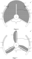
- Figure 6 shows a scenario according to an exemplary embodiment of the invention for a door system 1 designed as a revolving door.
- the door system 1 has, for example, a night closure in the form of two arcuate sliding door leaves 3, 3 ', which are retracted into an associated drum wall 7 when the door system 1 is in the open position.
- the turnstile 8 of the door system 1 is, for example, designed to have three leaves, so it includes three stationary door leaves 3.
- sensor devices 4 are designed so that they cover a detection area 5 filled here with black dots.
- the sliding door leaves 3, 3' preferably have sensor devices 4, 4 which cover detection areas 5', 5' filled with white dots. If an object is detected in the entire detection area 5, 5' formed in this way, the sliding door leaves 3, 3' are preferably stopped completely until no more object is detected. This ensures that, for example, a person is not trapped.
- FIG 7 shows a scenario according to another embodiment of the invention for the revolving door of Figure 6 .
- the sensor devices 4, not shown, on the sliding door leaves 3, 3 ' are preferably deactivated.
- Each detection area 5 is designed so that it has a larger area in the direction of rotation in front of the respective turnstile door leaf 3, 3', 3" and preferably additionally includes a slightly smaller area behind it. If the respective turnstile door leaf 3 is located outside the drum walls 7, 7 ', the respective detection area 5 also includes an area around its free end (cf.
- the detection area 5 ends at this free end (cf. lower two door leaves 3, 3 ').
- the "hiding" of the area around the respective free end can be done electronically by deactivating the sensor.
- the drum walls 7, 7' can, for example, be designed to be non-reflective on their insides, so that the sensors cannot detect an object in the area of the free ends.
- the rotation speed can be set so that, assuming constant relative speeds, the objects will have left the revolving door when the respective door leaf 3 corresponds to the horizontal position of the respective object Figure 7 seen achieved.
- the angular position of the respective turnstile door leaf 3, 3 ', 3" is also vertical in relation to the direction of passage Figure 7 consideration.
- Figure 8 shows a method for adjusting the detection range 5, 5 'of a sensor device 4, 4', according to an exemplary embodiment of the invention.
- This method relates to sensor devices 4 according to Figure 1 .
- a step S1 the current pivot angle and the height of the respective sensor device 4 above the floor in relation to the door system 1 are determined.
- the Detection geometry is determined, i.e. the dimensions of the associated detection area 5, 5 'in front of or around the respective door leaf 3, 3'.
- the detection area 5, 5' is preferably set automatically if the determined detection geometry does not correspond to the movement speed of the door leaf 3, 3'.
- the door system 1 is thus sensorically adjusted in relation to this door leaf 3, 3 '.
- Figure 9 shows an alternative method for adjusting the detection range 5, 5 'of the sensor device 4, 4', according to another exemplary embodiment of the invention.
- Step S1 is replaced by a step S4, according to which the values (here: pivot angle and height) are entered.
- Step S3 is replaced by a step S5, according to which the detection area 5, 5 'of the respective sensor device 4, 4' is displayed. I.e. the sensor device 4, 4' is not set automatically. This can be useful, for example, if the detection area 5, 5 'must be chosen to be larger than actually necessary for safety reasons. This also allows influences such as wind loads to be taken into account, which do not occur in a door system 1 located in a building.
- Figure 10 shows a method for operating the door system 1, according to an exemplary embodiment of the invention, which is preferably carried out before each door leaf movement.
- a process of determining the speed of movement of the door leaf 3 'in question i.e. when it moves
- the braking distance of the door leaf 3' is determined based on the previously determined detection area 5'. This can again be done by entering, by means of Reading out an assignment table or by means of a test drive. It is then checked in a step S8 whether braking in the detection area 5 'is safely possible. If this is the case (yes branch after step S8), the required safety reaction is determined in a subsequent step S12.
- a subsequent step S9 checks whether the maximum door leaf braking force has been set. If this is the case (yes branch after step S9), the movement speed of the door leaf 5 is reduced. This can be done in preset levels. The system then jumps back to step S7. Otherwise (no branch after step S9), the set braking force is also preferably increased gradually in a subsequent step S11. The system then also jumps back to step S7.
- Figure 11 shows the process of determining the door leaf movement speed of Figure 10 , i.e. step S6, in greater detail.
- a first step S60 the speed of the detected object is measured.
- the speed is preferably the aforementioned relative speed of this object to the relevant door leaf 3 '.
- the necessary movement speed of the relevant door leaf 3 ' is calculated in a subsequent step S61 on the basis of the object speed determined in this way. This process is then finished.
- the invention is not limited to the aforementioned exemplary embodiments. They can be exchanged for one another or combined with one another in parts or in part as a whole.
- step S4 can be extended in such a way that the current movement speed of the door leaf 3' is also included in the setting of the detection area 5'.
- the sensor device 4 ' can also be automatically adjusted during the door leaf movement. This is advantageous because when the door leaf 3 is moved from its rest position, the detection area 5 can be smaller than when the door leaf 3 'is moved. And if the door leaf 3' is braked or even accelerated due to a safety reaction or, for example, due to a wind load, the respective detection area 5' can be reduced or enlarged accordingly.
- the door system 1 comprises several door leaves 3, in particular movement-coupled ones (for example door leaves of the turnstile 8, a double-leaf sliding door with a belt drive, a double-leaf swing door with active and passive leaves), sensor signals from the sensor devices 4, 4 'of the door leaves can be processed together, for example in a logical OR-linked manner become.
- movement-coupled ones for example door leaves of the turnstile 8, a double-leaf sliding door with a belt drive, a double-leaf swing door with active and passive leaves
- sensor signals from the sensor devices 4, 4 'of the door leaves can be processed together, for example in a logical OR-linked manner become.
- it makes sense to couple the sensor devices of the sliding door leaves 3 accordingly with the sensor devices for the turnstile door leaves 3.
- the door system 1 can be of any type, for example a double-leaf swing door with active and passive leaves, a single-leaf sliding door, a folding door, a revolving door with a two or more than three-leaf turnstile with and without secondary closure, a one- or two-leaf telescopic sliding door, combined door systems such as a lock system with two individual door systems located one behind the other, for example in the form of sliding doors.
- the case can occur that several objects are detected at the same time, possibly with different relative velocities to one or more door leaves.
- the movement speed of the door leaf(s) is calculated so that: resulting relative speeds ⁇ 0. If this is not possible, for example because two objects approach a door leaf from both sides, two safety reactions can be provided. The first would be to stop the door immediately. The second safety reaction would be to brake the door leaf to a speed at which the relative speeds of both objects are the same or such that, assuming constant relative speeds, the door leaves cannot collide with any of the objects, since some objects have left the range of movement of the door leaf(s). . This is where the advantage of continuous monitoring of the relative speeds becomes apparent: If one of the objects stops or even moves away from the door leaf, the door leaf can, if necessary, be brought to a speed at which all relative speeds are all the same or less than 0.
- an adjustment process can be provided in which, if necessary, the braking force is initially gradually adjusted to the maximum.
- the detection range of the sensor device(s) 4, 4 ' is increased, which means a Reduction in braking force enabled. Then the setting process is (re)started again.
- the sensor devices 4 from Figure 1 can against the sensor devices 4 according to Figure 5 replaced or combined with each other.
- the invention creates a solution for a safe and yet fail-safe door system.
- downtimes of door systems can be reduced.
- the implementation of the invention is not limited to the preferred exemplary embodiment given above. Rather, a number of variants are conceivable, which make use of the solution presented even in fundamentally different designs. All features and/or advantages arising from the claims, the description or the drawings, including constructive details or spatial arrangements, can be essential to the invention both individually and in a wide variety of combinations.
Priority Applications (2)
| Application Number | Priority Date | Filing Date | Title |
|---|---|---|---|
| EP22190293.5A EP4321717A1 (fr) | 2022-08-12 | 2022-08-12 | Dispositif de sécurité pour une installation automatisée de porte, installation de porte équipée de celui-ci et procédé de fonctionnement d'une telle installation de porte |
| US18/446,974 US20240102330A1 (en) | 2022-08-12 | 2023-08-09 | Safety device for automated door systems, door system equipped therewith and operating method for such a door system |
Applications Claiming Priority (1)
| Application Number | Priority Date | Filing Date | Title |
|---|---|---|---|
| EP22190293.5A EP4321717A1 (fr) | 2022-08-12 | 2022-08-12 | Dispositif de sécurité pour une installation automatisée de porte, installation de porte équipée de celui-ci et procédé de fonctionnement d'une telle installation de porte |
Publications (1)
| Publication Number | Publication Date |
|---|---|
| EP4321717A1 true EP4321717A1 (fr) | 2024-02-14 |
Family
ID=82932518
Family Applications (1)
| Application Number | Title | Priority Date | Filing Date |
|---|---|---|---|
| EP22190293.5A Pending EP4321717A1 (fr) | 2022-08-12 | 2022-08-12 | Dispositif de sécurité pour une installation automatisée de porte, installation de porte équipée de celui-ci et procédé de fonctionnement d'une telle installation de porte |
Country Status (2)
| Country | Link |
|---|---|
| US (1) | US20240102330A1 (fr) |
| EP (1) | EP4321717A1 (fr) |
Citations (4)
| Publication number | Priority date | Publication date | Assignee | Title |
|---|---|---|---|---|
| EP2075397A2 (fr) * | 2007-12-28 | 2009-07-01 | GEZE GmbH | Système de sécurité pour un battant pivotant motorisé |
| EP1653035B1 (fr) * | 2004-10-29 | 2014-12-24 | Gretsch-Unitas GmbH Baubeschläge | Ferrure pour porte coulissante |
| EP3026457A1 (fr) | 2014-11-27 | 2016-06-01 | GEZE GmbH | Dispositif de surveillance d'un champ de detection |
| JPWO2018043511A1 (ja) * | 2016-08-29 | 2019-06-24 | ナブテスコ株式会社 | 自動ドア、自動ドアセンサおよび自動ドアの開閉方法 |
-
2022
- 2022-08-12 EP EP22190293.5A patent/EP4321717A1/fr active Pending
-
2023
- 2023-08-09 US US18/446,974 patent/US20240102330A1/en active Pending
Patent Citations (4)
| Publication number | Priority date | Publication date | Assignee | Title |
|---|---|---|---|---|
| EP1653035B1 (fr) * | 2004-10-29 | 2014-12-24 | Gretsch-Unitas GmbH Baubeschläge | Ferrure pour porte coulissante |
| EP2075397A2 (fr) * | 2007-12-28 | 2009-07-01 | GEZE GmbH | Système de sécurité pour un battant pivotant motorisé |
| EP3026457A1 (fr) | 2014-11-27 | 2016-06-01 | GEZE GmbH | Dispositif de surveillance d'un champ de detection |
| JPWO2018043511A1 (ja) * | 2016-08-29 | 2019-06-24 | ナブテスコ株式会社 | 自動ドア、自動ドアセンサおよび自動ドアの開閉方法 |
Also Published As
| Publication number | Publication date |
|---|---|
| US20240102330A1 (en) | 2024-03-28 |
Similar Documents
| Publication | Publication Date | Title |
|---|---|---|
| DE102008044990B4 (de) | Verfahren und Vorrichtung zur Ansteuerung und/oder Überwachung eines motorisch angetriebenen Flügels während der Öffnungsphase | |
| DE3618692C2 (fr) | ||
| EP3581747B1 (fr) | Dispositif de surveillance | |
| EP2075397A2 (fr) | Système de sécurité pour un battant pivotant motorisé | |
| DE19653026B4 (de) | Vorrichtung zur Ansteuerung und/oder Absicherung eines motorisch angetriebenen Flügels einer Tür, eines Fensters oder dergleichen | |
| DE10348917B4 (de) | Türstoppsystem mit Hinderniserkennung | |
| EP3660251B1 (fr) | Dispositif de protection, en particulier portail industriel | |
| WO2011095474A1 (fr) | Dispositif d'entraînement de porte, fermeture de bâtiment ainsi équipée, système de porte et procédé de fabrication et d'entraînement | |
| EP2005820A2 (fr) | Porte, comme en particulier une porte d'entrée d'une boîte de ramassage automatique pour animaux | |
| EP4321717A1 (fr) | Dispositif de sécurité pour une installation automatisée de porte, installation de porte équipée de celui-ci et procédé de fonctionnement d'une telle installation de porte | |
| EP0902152B1 (fr) | Porte tournante à limitation de vitesse de rotation | |
| EP0935044A2 (fr) | Procédé et dispositif de commande et/ou de surveillance d'une porte motorisée | |
| EP3695081B1 (fr) | Élément de porte inférieur comportant un support à rouleau pivotant | |
| DE102013212518A1 (de) | Automatische Fenster- oder Türanlage | |
| WO2019162092A1 (fr) | Prévention des collisions entre cabines d'ascenseur | |
| EP1612363B1 (fr) | Ensemble de porte coulissante automatique | |
| EP3554915A1 (fr) | Porte coulissante et louvoyante pour véhicules comprenant au moins un battant de porte et un entraînement à broche | |
| DE19637452C2 (de) | Verriegelungsvorrichtung zwischen einem Zargenrahmen und einem im Schließzustand in diesen eingreifenden Torblatt | |
| EP3898487A1 (fr) | Commande de porte et système de commande de porte pour la commande de mouvements de déplacement d'au moins un vantail de porte d'une porte d'ascenseur | |
| EP1775409A2 (fr) | Dispositif d'obturation d'un bâtiment ou d'un chantier avec surveillance de la zone de pivotement des battants pivotants | |
| EP1884615B1 (fr) | Procédé destiné au fonctionnement d'une installation de porte coulissante automatique | |
| EP2388424A2 (fr) | Dispositif d'entraînement de porte et installation de porte en étant équipée | |
| EP3963164A1 (fr) | Unité de commande conçue pour un entraînement de porte ou de fenêtre | |
| DE2901494C3 (de) | Drehtüranordnung | |
| EP3853164B1 (fr) | Cabine d'ascenseur, installation d'ascenseur et procédé de fonctionnement d'une installation d'ascenseur |
Legal Events
| Date | Code | Title | Description |
|---|---|---|---|
| PUAI | Public reference made under article 153(3) epc to a published international application that has entered the european phase |
Free format text: ORIGINAL CODE: 0009012 |
|
| STAA | Information on the status of an ep patent application or granted ep patent |
Free format text: STATUS: THE APPLICATION HAS BEEN PUBLISHED |
|
| AK | Designated contracting states |
Kind code of ref document: A1 Designated state(s): AL AT BE BG CH CY CZ DE DK EE ES FI FR GB GR HR HU IE IS IT LI LT LU LV MC MK MT NL NO PL PT RO RS SE SI SK SM TR |