EP4321273A1 - Werkstückmanipulator - Google Patents
Werkstückmanipulator Download PDFInfo
- Publication number
- EP4321273A1 EP4321273A1 EP23189771.1A EP23189771A EP4321273A1 EP 4321273 A1 EP4321273 A1 EP 4321273A1 EP 23189771 A EP23189771 A EP 23189771A EP 4321273 A1 EP4321273 A1 EP 4321273A1
- Authority
- EP
- European Patent Office
- Prior art keywords
- manipulator
- workpiece
- tongs
- forging
- frame
- Prior art date
- Legal status (The legal status is an assumption and is not a legal conclusion. Google has not performed a legal analysis and makes no representation as to the accuracy of the status listed.)
- Granted
Links
Images
Classifications
-
- B—PERFORMING OPERATIONS; TRANSPORTING
- B21—MECHANICAL METAL-WORKING WITHOUT ESSENTIALLY REMOVING MATERIAL; PUNCHING METAL
- B21J—FORGING; HAMMERING; PRESSING METAL; RIVETING; FORGE FURNACES
- B21J13/00—Details of machines for forging, pressing, or hammering
- B21J13/08—Accessories for handling work or tools
- B21J13/10—Manipulators
-
- B—PERFORMING OPERATIONS; TRANSPORTING
- B21—MECHANICAL METAL-WORKING WITHOUT ESSENTIALLY REMOVING MATERIAL; PUNCHING METAL
- B21J—FORGING; HAMMERING; PRESSING METAL; RIVETING; FORGE FURNACES
- B21J13/00—Details of machines for forging, pressing, or hammering
- B21J13/08—Accessories for handling work or tools
- B21J13/10—Manipulators
- B21J13/12—Turning means
-
- B—PERFORMING OPERATIONS; TRANSPORTING
- B21—MECHANICAL METAL-WORKING WITHOUT ESSENTIALLY REMOVING MATERIAL; PUNCHING METAL
- B21J—FORGING; HAMMERING; PRESSING METAL; RIVETING; FORGE FURNACES
- B21J7/00—Hammers; Forging machines with hammers or die jaws acting by impact
- B21J7/02—Special design or construction
- B21J7/14—Forging machines working with several hammers
Definitions
- the invention relates to a workpiece manipulator for use with a radial forging press, with workpiece tongs, the workpiece tongs being attached to a manipulator frame guided linearly on a manipulator track and the workpiece tongs forming a chuck with a fixed clamping axis which extends in the forging axis or parallel to the forging axis , so that the workpiece can be manipulated with a linear translational movement of the manipulator frame.
- a workpiece manipulator or forging manipulator is, for example, from the DE 10 2012 217 650 A1 known.
- the publication describes a forging manipulator with a tongs carrier for arranging a workpiece tong, the tongs carrier being arranged in a translationally movable manipulator frame and being variably positioned relative to the manipulator frame for handling a workpiece held in the workpiece tongs, and the tongs carrier on a translation axis via a spring device with the manipulator frame is connected, the spring device being provided with a switching device for the defined release of the energy stored in the spring device.
- Forging manipulators of the type mentioned in this publication are used in so-called open-die forging, in which the workpiece to be processed in a forging device designed as a forging press is held in a tong carrier of the forging manipulator and is moved into one by means of lifting, tilting or rotating movements of the tongs arranged in a manipulator frame of the forging manipulator desired relative position is brought to the forging press in order to be formed in a defined manner by means of a press part of the forging device.
- the block to be forged is formed by several, usually four, forging tools that attack the circumference of the block simultaneously and synchronously, while the forging manipulator holds the rear end of the block or ingot. This results in the need to grip and hold the workpiece in the forging axis by the forging manipulator, whereby manipulation of the forging workpiece is naturally only possible in the translation axis of the forging manipulator.
- the loading system includes a linear guide system for the forging manipulator, which is integrated into a manipulator track below a floor level of the forging manipulator.
- Loss lubrication of the type described above is associated with the disadvantage of high investment and maintenance costs.
- the invention is therefore based on the object of providing a workpiece manipulator or forging manipulator for use with a radial forging press, which requires less maintenance.
- the invention is also based on the object of providing a workpiece manipulator for use with a radial forging press, which is suitable for absorbing the forces resulting from the forging process.
- a workpiece manipulator for use with a radial forging press, the workpiece tongs being attached to a manipulator frame guided linearly on a manipulator track and the workpiece tongs forming a chuck with a fixed clamping axis which extends in the forging axis or parallel to the forging axis , so that the workpiece can be manipulated with a linear translational movement.
- the manipulator frame is expediently guided on rails on wheels during the translational movement.
- the workpiece manipulator is expediently designed in such a way that only a single linear manipulation movement is possible, preferably in the forging axis or in the translation axis of the manipulator frame.
- the workpiece manipulator also expediently has a degree of rotational freedom, so that the workpiece, which is held by the workpiece tongs, can be rotated through an angle during successive tool movements.
- the manipulator frame is expediently guided linearly, for which purpose the workpiece manipulator is preferably guided by means of at least two guide rails or guide tracks laid within a hallway level.
- the manipulator frame comprises a chassis which is sprung and/or damped.
- This design has the advantage that the vertical forces resulting from the forging process are absorbed or cushioned and/or dampened in the form of shocks or impacts, thereby alleviating the forces acting on individual wheels or rollers of the chassis.
- the chassis can include a variety of wheel groups.
- the wheel groups can each include a wheel carrier with a large number of wheels.
- the impeller groups or the impeller carriers can each be mounted in a swinging/rocking manner in order to increase the load capacity of the individual impellers.
- the wheel carriers are each pivotally articulated to the manipulator frame.
- a total of four impeller groups can be provided on the manipulator frame, wherein the manipulator frame can each have two front and two rear impeller groups.
- the front wheel groups are expediently arranged at the same height on a side of the manipulator frame facing a tongs carrier.
- the rear impeller groups can be arranged on the side of the manipulator frame facing away from the tongs carrier.
- At least two impeller groups are each provided with spring and/or damper elements.
- the two front impeller groups i.e. the impeller groups arranged closest to the workpiece tongs, are provided with spring and/or damper elements.
- the spring and/or damper elements can be designed as simple spring dampers or as spring elements with an additional hydraulic damping system.
- each wheel carrier is supported on the manipulator frame with a large number of spring and/or damper elements.
- a spring and/or damper element can be provided for each individual wheel arranged on the wheel carrier, so that the number of spring and/or damper elements corresponds to the number of wheels.
- the springs are preferably pretensioned in such a way that the manipulator's own weight is supported. When the manipulator is placed on the road, the springs are relieved of the load.
- each wheel carrier can comprise four wheels and four spring and/or damper elements.
- At least first front impeller groups and second rear impeller groups are provided on the manipulator frame in the direction of the translational movement, the first impeller groups being at a first small distance from the workpiece tongs or a tong carrier and the second impeller groups having a second larger distance from the workpiece tongs or are arranged on the pliers carrier.
- the wheels interact with one or more guideways or one or more guide rails that extend within the floor level of the radial forging press.
- Brushes are expediently provided in front of and/or behind at least one impeller carrier, preferably in front of and/or behind all impeller carriers, which brush off any scale that may be on the guide track during the translational movement of the workpiece manipulator.
- the workpiece pliers expediently comprises a large number of pliers legs arranged at the same distance on a radius around the fixed clamping axis.
- the workpiece pliers preferably comprise four pliers legs distributed at an equal distance of 90° along the radius.
- the invention also relates to a system for manipulating a forged workpiece on a radial forging press, comprising a workpiece manipulator with a workpiece tong, which is preferably attached to a tongs carrier, the workpiece tongs being attached to a manipulator frame guided linearly on a manipulator track and the workpiece tongs having a chuck with a fixed clamping axis, which extends in the forging axis or parallel to the forging axis, so that the tool can be manipulated with a linear translational movement, the manipulator frame being guided on rails on wheels during the translational movement.
- the system also includes a manipulator track with at least two guide rails laid within a hallway level, which form a guide track for the workpiece manipulator.
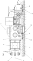
- the workpiece manipulator 1 which is designed as a forging manipulator for a radial forging press, comprises a manipulator frame 2 with a tongs carrier 3 with a workpiece tongs 4 attached thereto.
- the workpiece tongs 4 comprises four arranged at the same distance from one another on a radius around a fixed clamping axis 5 Pliers legs 6. When actuated, the pliers legs 6 perform a synchronous opening and closing movement in the same direction with respect to the clamping axis 5.
- the workpiece manipulator 1 can be moved linearly on a floor level 7 in front of a radial forging press, not shown, with the clamping axis 5 of the workpiece manipulator 1 extending within the forging axis of the radial forging press.
- the workpiece, not shown, in the form of a block to be forged or an ingot is held at the end by the workpiece tongs 4 and fed to the radial forging press via a linear movement of the workpiece manipulator 1.
- the workpiece or the forging block gripped with the workpiece tongs 4, which was previously raised from a furnace in the forging heat to the height of the forging axis and then clamped by the workpiece tongs 4 in the forging axis or in the clamping axis 5, can be moved via a linear
- the movement of the manipulator frame 2 on a guide track 8 during the forging process can only be moved linearly in accordance with the translational movement of the manipulator frame 2.
- the workpiece tongs 4 can be rotated about the clamping axis 5.
- the manipulator frame 2 includes a chassis that includes two first front wheel carriers 9 and two second rear wheel carriers 10.
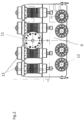
- the impeller carriers 9, 10 are pivotally connected to the manipulator frame 2 about a pivot axis 11 and each include four impellers 12 (see detailed view according to Figure 2 ).
- the running wheels 12 are each supported on a guide track 8 designed as a guide rail.
- the first front wheel carriers 9 are also supported against the manipulator frame 2 via spring/damping elements 13.
- the second rear wheel carriers 10, on the other hand, are articulated to the manipulator frame 2 without suspension.
Landscapes
- Engineering & Computer Science (AREA)
- Mechanical Engineering (AREA)
- Forging (AREA)
Abstract
Description
- Die Erfindung betrifft einen Werkstückmanipulator zur Verwendung mit einer Radialschmiedepresse, mit einer Werkstückzange, wobei die Werkstückzange an einem linear auf einer Manipulatorfahrbahn geführten Manipulatorgestell befestigt ist und wobei die Werkstückzange ein Spannfutter mit einer festen Spannachse bildet, die sich in der Schmiedeachse oder parallel zur Schmiedeachse erstreckt, so dass das Werkstück mit einer linearen Translationsbewegung des Manipulatorgestells manipulierbar ist.
- Ein Werkstückmanipulator bzw. Schmiedemanipulator ist beispielsweise aus der
DE 10 2012 217 650 A1 bekannt. Die Druckschrift beschreibt einen Schmiedemanipulator mit einem Zangenträger zur Anordnung einer Werkstückzange, wobei der Zangenträger in einem translatorisch bewegbaren Manipulatorrahmen angeordnet und zur Handhabung eines in der Werkstückzange aufgenommenen Werkstücks gegenüber dem Manipulatorrahmen veränderbar positionierbar ist, und der Zangenträger auf einer Translationsachse über eine Federeinrichtung mit dem Manipulatorrahmen verbunden ist, wobei zur definierten Freigabe der in der Federeinrichtung gespeicherten Energie die Federeinrichtung mit einer Schalteinrichtung versehen ist. - Schmiedemanipulatoren der in dieser Veröffentlichung genannten Art werden beim sogenannten Freiformschmieden eingesetzt, bei dem das in einer als Schmiedepresse ausgebildeten Schmiedeeinrichtung zu bearbeitende Werkstück in einem Zangenträger des Schmiedemanipulators gehalten und mittels Hub-, Kipp- oder Drehbewegung der in einem Manipulatorrahmen des Schmiedemanipulators angeordneten Zange in eine gewünschte relative Position zur Schmiedepresse gebracht wird, um mittels eines Pressenteils der Schmiedeeinrichtung definiert umgeformt zu werden.
- Beim Freiformschmieden ist es erforderlich, das Werkstück mit dem halben Pressenhub aktiv hydraulisch mitzuführen, wobei eine Dämpfung von Schlägen und Stößen aus dem Schmiedeprozess über die Hydraulik des Manipulators ausgeglichen wird.
- Beim Radialschmiedepressen ist es üblich, den Schmiedemanipulator in einer Manipulatorfahrbahn linear zu führen. In einer Radialschmiedepresse erfolgt die Umformung des zu schmiedenden Blocks durch mehrere, in der Regel vier, am Umfang des Blocks zeitgleich und synchron angreifende Schmiedewerkzeuge, während der Schmiedemanipulator das hintere Ende des Blocks bzw. des Ingot festhält. Daraus ergibt sich die Notwendigkeit, das Werkstück durch den Schmiedemanipulator in der Schmiedeachse zu greifen und zu halten, wobei eine Manipulation des Schmiedewerkstücks naturgemäß nur in der Translationsachse des Schmiedemanipulators möglich ist.
- Aus der
DE 10 2014 226 384 A1 sind beispielsweise ein Ladesystem und ein Ladeverfahren für Radialschmiedepressen bekannt. Das Ladesystem umfasst ein Linear-Führungssystem für den Schmiedemanipulator, welches in eine Manipulatorfahrbahn unterhalb einer Flurebene des Schmiedemanipulators integriert ist. - Es ist grundsätzlich bekannt, die horizontale Führung des Schmiedemanipulators als Gleitführung auszuführen. Eine solche Gleitführung besitzt den Nachteil, dass auf der vollständigen Führungslänge dauerhaft ein Ölfilm zur Reibungs- und Verschleißminderung aufgebracht werden muss. Die benötigte Ölmenge ergibt sich dabei nicht nur aus der zum reinen Schmieren erforderlichen Menge, sondern es müssen zusätzlich aus dem Prozess anfallende Verschmutzungen in Form von Zunder von der Führungsbahn abgespült werden. Dies erfordert eine große Ölmenge, die permanent aufgebracht, kontrolliert und wieder abgeleitet sowie aufbereitet werden muss. Das erfordert weiterhin ein entsprechend aufwendig gestaltetes Fundament und/oder einen Keller unterhalb der Flurebene, in dem die für die Schmierung erforderlichen Aggregate untergebracht werden müssen.
- Eine Verlustschmierung der vorstehend beschriebenen Art ist mit dem Nachteil hoher Investitions- und Wartungskosten verbunden.
- Der Erfindung liegt daher die Aufgabe zugrunde, einen Werkstückmanipulator bzw. Schmiedemanipulator zur Verwendung mit einer Radialschmiedepresse bereitzustellen, der einen geringeren Wartungsaufwand erfordert.
- Der Erfindung liegt weiterhin die Aufgabe zugrunde, einen Werkstückmanipulator zur Verwendung mit einer Radialschmiedepresse bereitzustellen, der zur Aufnahme der aus dem Schmiedeprozess resultierenden Kräfte geeignet ist.
- Die der Erfindung zugrunde liegende Aufgabe wird gelöst durch einen Werkstückmanipulator zur Verwendung mit einer Radialschmiedepresse mit den Merkmalen des Anspruchs 1. Vorteilhafte Ausgestaltungen der Erfindung ergeben sich aus den Unteransprüchen.
- Nach einem Gesichtspunkt der Erfindung wird ein Werkstückmanipulator zur Verwendung mit einer Radialschmiedepresse bereitgestellt, wobei die Werkstückzange an einem linear auf einer Manipulatorfahrbahn geführten Manipulatorgestell befestigt ist und wobei die Werkstückzange ein Spannfutter mit einer festen Spannachse bildet, die sich in der Schmiedeachse oder parallel zur Schmiedeachse erstreckt, so dass das Werkstück mit einer linearen Translationsbewegung manipulierbar ist.
- Zweckmäßigerweise ist das Manipulatorgestell während der Translationsbewegung schienengebunden auf Laufrädern geführt.
- Der Werkstückmanipulator ist zweckmäßigerweise so ausgebildet, dass nur eine einzige lineare Manipulationsbewegung, vorzugsweise in der Schmiedeachse bzw. in der Translationsachse des Manipulatorgestells, möglich ist. Der Werkstückmanipulator weist weiterhin zweckmäßigerweise einen Drehfreiheitsgrad auf, so dass das Werkstück, welches von der Werkstückzange gehalten wird, während nacheinander ablaufender Werkzeugbewegungen um einen Winkel gedreht werden kann.-
- Das Manipulatorgestell ist zweckmäßigerweise linear geführt, wobei hierzu der Werkstückmanipulator vorzugsweise mittels wenigstens zweier innerhalb einer Flurebene verlegten Führungsschienen oder Führungsbahnen geführt ist.
- Bei einer zweckmäßigen bevorzugten Variante des Werkstückmanipulators gemäß der Erfindung ist vorgesehen, dass das Manipulatorgestell ein Fahrwerk umfasst, welches gefedert und/oder gedämpft ist. Diese Ausführung hat den Vorzug, dass die aus dem Schmiedeprozess resultierenden vertikalen Kräfte in Form von Stößen oder Schlägen abgefangen bzw. abgefedert und/oder gedämpft werden, wodurch die auf einzelne Laufräder oder auch Rollen des Fahrwerks wirkenden Kräfte abgemildert werden.
- Das Fahrwerk kann eine Vielzahl von Laufradgruppen umfassen. Die Laufradgruppen können jeweils einen Laufradträger mit einer Vielzahl von Laufrädern umfassen.
- Die Laufradgruppen bzw. die Laufradträger können jeweils schwingend/wippend gelagert sein, um den Traganteil der einzelnen Laufräder zu erhöhen. Hierzu kann beispielsweise vorgesehen sein, dass die Laufradträger jeweils schwenkbar an dem Manipulatorgestell angelenkt sind.
- An dem Manipulatorgestell können beispielsweise insgesamt vier Laufradgruppen vorgesehen sein, wobei das Manipulatorgestell jeweils zwei vordere und zwei hintere Laufradgruppen aufweisen kann. Die vorderen Laufradgruppen sind zweckmäßigerweise auf gleicher Höhe auf einer einem Zangenträger zugewandten Seite des Manipulatorgestells angeordnet. Die hinteren Laufradgruppen können auf der dem Zangenträger abgewandten Seite des Manipulatorgestells angeordnet sein.
- Bei einer besonders zweckmäßigen und vorteilhaften Ausführungsform des Werkstückmanipulators gemäß der Erfindung ist vorgesehen, dass wenigstens zwei Laufradgruppen jeweils mit Feder- und/oder Dämpferelementen versehen sind. In einer besonderen Ausgestaltung sind die beiden vorderen Laufradgruppen, d.h, die zu der Werkstückzange nächstliegend angeordneten Laufradgruppen, mit Feder- und/oder Dämpferelementen versehen. Die Feder- und/oder Dämpferelemente können als einfache Federdämpfer oder als Federelemente mit einem zusätzlichen hydraulischen Dämpfungssystem ausgebildet sein.
- Vorzugsweise ist jeder Laufradträger mit einer Vielzahl von Feder- und/oder Dämpferelementen an dem Manipulatorgestell abgestützt. Für jedes einzelne an dem Laufradträger angeordnete Laufrad kann ein Feder- und/oder Dämpferelement vorgesehen sein, sodass die Anzahl der Feder- und/oder Dämpferelemente der Anzahl der Laufräder entspricht. Die Federn sind vorzugsweise derart vorgespannt, dass das Eigengewicht des Manipulators getragen wird. Wenn der Manipulator auf die Fahrbahn gesetzt wird, findet somit findet eine Entlastung der Federn statt.
- Bei einer zweckmäßigen Variante des Werkstückmanipulators kann jeder Laufradträger vier Laufräder und vier Feder- und/oder Dämpferelemente umfassen.
- Zweckmäßigerweise sind an dem Manipulatorgestell wenigstens erste in Richtung der Translationsbewegung vordere Laufradgruppen und zweite hintere Laufradgruppen vorgesehen, wobei die ersten Laufradgruppen mit einem ersten kleinen Abstand zu der Werkstückzange bzw. zu einem Zangenträger und die zweiten Laufradgruppen mit einem zweiten größeren Abstand zu der Werkstückzange bzw. dem Zangenträger angeordnet sind.
- Wie vorstehend bereits erwähnt, wirken die Laufräder mit einer oder mehreren Führungsbahnen oder einer oder mehreren Führungsschienen zusammen, die sich innerhalb der Flurebene der Radialschmiedepresse erstrecken. Zweckmäßigerweise sind vor und/oder hinter mindestens einem Laufradträger, vorzugsweise vor und/oder hinter allen Laufradträgern Bürsten vorgesehen, die während der Translationsbewegung des Werkstückmanipulators auf der Führungsbahn etwa befindlichen Zunder abbürsten.
- Die Werkstückzange umfasst zweckmäßigerweise eine Vielzahl von mit gleichem Abstand auf einem Radius um die feste Spannachse angeordnete Zangenschenkel. Vorzugsweise umfasst die Werkstückzange vier mit einem gleichen Abstand von 90° auf dem Radius verteilt angeordnete Zangenschenkel.
- Gegenstand der Erfindung ist auch ein System zur Manipulation eines Schmiedewerkstücks an einer Radialschmiedepresse umfassend einen Werkstückmanipulator mit einer Werkstückzange, die vorzugsweise an einem Zangenträger befestigt ist, wobei die Werkstückzange an einem linear auf einer Manipulatorfahrbahn geführten Manipulatorgestell befestigt ist und wobei die Werkstückzange ein Spannfutter mit einer festen Spannachse bildet, die sich in der Schmiedeachse oder parallel zur Schmiedeachse erstreckt, sodass das Werkzeug mit einer linearen Translationsbewegung manipulierbar ist, wobei das Manipulatorgestell während der Translationsbewegung schienengebundenen auf Laufrädern geführt ist. Das System umfasst weiterhin eine Manipulatorfahrbahn mit wenigstens zwei innerhalb einer Flurebene verlegten Führungsschienen, die eine Führungsbahn für den Werkstückmanipulator bilden.
- Die Erfindung wird nachstehend unter Bezugnahme auf ein in den Zeichnungen dargestelltes Ausführungsbeispiel erläutert.
- Es zeigen:
- Figur 1
- eine schematische Darstellung des Werkstückmanipulators gemäß der Erfindung und
- Figur 2
- eine Detailansicht eines Teils des Fahrwerks des Werkstückmanipulators aus
Figur 1 . - Der Werkstückmanipulator 1 gemäß der Erfindung, der als Schmiedemanipulator für eine Radialschmiedepresse ausgebildet ist, umfasst ein Manipulatorgestell 2 mit einem Zangenträger 3 mit einer an diesem befestigten Werkstückzange 4. Die Werkstückzange 4 umfasst vier mit gleichem Abstand zueinander auf einem Radius um eine feste Spannachse 5 angeordnete Zangenschenkel 6. Die Zangenschenkel 6 vollziehen bei Betätigung eine gleichsinnige und synchrone Öffnungs- und Schließbewegung bezüglich der Spannachse 5.
- Der Werkstückmanipulator 1 ist auf einer Flurebene 7 vor einer nicht dargestellten Radialschmiedepresse linear verfahrbar, wobei sich die Spannachse 5 des Werkstückmanipulators 1 innerhalb der Schmiedeachse der Radialschmiedepresse erstreckt. Das nicht gezeigte Werkstück in Form eines zu schmiedenden Blocks oder eines Ingot wird endseitig von der Werkstückzange 4 gehalten und über eine lineare Verfahrbewegung des Werkstückmanipulators 1 der Radialschmiedepresse zugeführt.
- Das mit der Werkstückzange 4 ergriffene Werkstück bzw. der Schmiedeblock, der zuvor aus einem Ofen in der Schmiedehitze auf die Höhe der Schmiedeachse angehoben wurde und sodann von der Werkstückzange 4 in der Schmiedeachse bzw. in der Spannachse 5 eingespannt wurde, lässt sich über eine lineare Verfahrbewegung des Manipulatorgestells 2 auf einer Führungsbahn 8 während des Schmiedevorgangs in nur linear entsprechend der Translationsbewegung des Manipulatorgestells 2 bewegen. Darüber hinaus ist die Werkstückzange 4 um die Spannachse 5 drehbar. Das Manipulatorgestell 2 umfasst ein Fahrwerk, das zwei erste vordere Laufradträger 9 und zwei zweite hintere Laufradträger 10 umfasst. Die Laufradträger 9,10 sind um eine Schwenkachse 11 des Manipulatorgestells 2 schwenkbar an diesem angelenkt und umfassen jeweils vier Laufräder 12 (siehe Detailansicht gemäß
Figur 2 ). - Die Laufräder 12 sind jeweils auf einer als Führungsschiene ausgebildeten Führungsbahn 8 abgestützt. Die ersten vorderen Laufradträger 9 sind darüber hinaus über Feder-/Dämpfungselemente 13 gegen das Manipulatorgestell 2 abgestützt. Die zweiten hinteren Laufradträger 10 sind hingegen ungefedert an dem Manipulatorgestell 2 angelenkt.
-
- 1
- Werkstückmanipulator
- 2
- Manipulatorgestell
- 3
- Zangenträger
- 4
- Werkstückzange
- 5
- Spannachse
- 6
- Zangenschenkel
- 7
- Flurebene
- 8
- Führungsbahn
- 9
- erste Laufradträger
- 10
- zweite Laufradträger
- 11
- Schwenkachsen
- 12
- Laufräder
- 13
- Feder-/Dämpfungselement
Claims (9)
- Werkstückmanipulator (1) zur Verwendung mit einer Radialschmiedepresse, mit einer Werkstückzange (4), wobei die Werkstückzange (4) an einem linear auf einer Manipulatorfahrbahn geführten Manipulatorgestell (2) befestigt ist und wobei die Werkstückzange (4) ein Spannfutter mit einer festen Spannachse (5) bildet, die sich in der Schmiedeachse erstreckt, so dass das Werkstück mit einer linearen Translationsbewegung manipulierbar ist, wobei das Manipulatorgestell (2) während der Translationsbewegung schienengebunden auf Laufrädern (12) geführt ist.
- Werkstückmanipulator (1) nach Anspruch 1, dadurch gekennzeichnet, dass das Manipulatorgestell (2) ein Fahrwerk umfasst, welches gefedert und/oder gedämpft ist.
- Werkstückmanipulator (1) nach einem der Ansprüche 1 oder 2, dadurch gekennzeichnet, dass das Fahrwerk eine Vielzahl von Laufradgruppen umfasst.
- Werkstückmanipulator (1) nach Anspruch 3, dadurch gekennzeichnet, dass die Laufradgruppen jeweils wenigstens einen Laufradträger (9,10) mit einer Vielzahl von Laufrädern (12) umfassen.
- Werkstückmanipulator (1) nach Anspruch 4, dadurch gekennzeichnet, dass die Laufradträger (9,10) jeweils schwenkbar an dem Manipulatorgestell (2) angelenkt sind.
- Werkstückmanipulator (1) nach einem der Ansprüche 1 bis 5, dadurch gekennzeichnet, dass wenigstens zwei Laufradgruppen, vorzugsweise zwei vordere, jeweils mit Feder- und/oder Dämpferelementen (13) versehen sind.
- Werkstückmanipulator (1) nach einem der Ansprüche 4 bis 6, dadurch gekennzeichnet, dass jeder Laufradträger (9,10) mit einer Vielzahl von Feder- und/oder Dämpferelementen (13) an dem Manipulatorgestell (2) abgestützt ist.
- Werkstückmanipulator (1) nach einem der Ansprüche 1 bis 7, dadurch gekennzeichnet, dass die Werkstückzange (4) eine Vielzahl von mit gleichem Abstand auf einem Radius um die feste Spannachse (5) angeordnete Zangenschenkel (6) umfasst.
- System zur Manipulation eines Schmiedewerkstücks an einer Radialschmiedepresse umfassend einen Werkstückmanipulator (1) mit den Merkmalen eines der Ansprüche 1 bis 8 sowie eine Manipulatorfahrbahn mit wenigstens zwei in einer Flurebene (7) verlegten Führungsschienen.
Applications Claiming Priority (1)
| Application Number | Priority Date | Filing Date | Title |
|---|---|---|---|
| DE102022208238.9A DE102022208238A1 (de) | 2022-08-08 | 2022-08-08 | Werkstückmanipulator |
Publications (2)
| Publication Number | Publication Date |
|---|---|
| EP4321273A1 true EP4321273A1 (de) | 2024-02-14 |
| EP4321273B1 EP4321273B1 (de) | 2025-07-09 |
Family
ID=87557919
Family Applications (1)
| Application Number | Title | Priority Date | Filing Date |
|---|---|---|---|
| EP23189771.1A Active EP4321273B1 (de) | 2022-08-08 | 2023-08-04 | Werkstückmanipulator |
Country Status (3)
| Country | Link |
|---|---|
| US (1) | US20240042511A1 (de) |
| EP (1) | EP4321273B1 (de) |
| DE (1) | DE102022208238A1 (de) |
Families Citing this family (1)
| Publication number | Priority date | Publication date | Assignee | Title |
|---|---|---|---|---|
| CN117943508B (zh) * | 2024-03-26 | 2024-06-04 | 溧阳市金昆锻压有限公司 | 一种齿轮锻压用定位机构 |
Citations (9)
| Publication number | Priority date | Publication date | Assignee | Title |
|---|---|---|---|---|
| DE2030473A1 (de) * | 1969-07-28 | 1971-02-18 | Gesellschaft fur Fertigungstechnik u Maschinenbau GmbH, Steyr (Osterreich) | Spannkopf fur Schmiedemaschinen |
| DE3726763A1 (de) * | 1986-08-21 | 1988-03-03 | Hasenclever Maschf Sms | Schmiedemanipulator |
| JPS63180337A (ja) * | 1987-01-22 | 1988-07-25 | Ishikawajima Harima Heavy Ind Co Ltd | パイプの製造装置 |
| WO1988006498A1 (en) * | 1987-03-03 | 1988-09-07 | Davy Mckee (Sheffield) Limited | A manipulator for metal ingots |
| JPH05285584A (ja) * | 1992-04-07 | 1993-11-02 | Ishikawajima Harima Heavy Ind Co Ltd | マニプレータ |
| EP2243572A2 (de) * | 2009-04-23 | 2010-10-27 | SMS Meer GmbH | Manipulator für Schmiedemaschinen |
| DE102012217650A1 (de) | 2012-09-27 | 2014-03-27 | Dango & Dienenthal Maschinenbau Gmbh | Schmiedemanipulator sowie Verfahren zum Betrieb eines Schmiedemanipulators |
| DE102014226384A1 (de) | 2014-12-18 | 2016-06-23 | Sms Group Gmbh | Ladesystem und Ladeverfahren für Schmiedemaschinen |
| CN111167989A (zh) * | 2019-11-28 | 2020-05-19 | 青岛衡均锻压机械有限公司 | 一种卧式径向锻造机 |
Family Cites Families (9)
| Publication number | Priority date | Publication date | Assignee | Title |
|---|---|---|---|---|
| US2720800A (en) * | 1950-11-30 | 1955-10-18 | Wellman Smith Owen Eng Co Ltd | Forging manipulator |
| US2758734A (en) * | 1953-05-15 | 1956-08-14 | Vulcan Res Corp | Straddle truck-mounted material gripping and handling device |
| GB1186391A (en) * | 1967-01-16 | 1970-04-02 | Davy & United Eng Co Ltd | Manipulator |
| US3631996A (en) * | 1970-06-11 | 1972-01-04 | Alliance Machine Co | Manipulator |
| DE2112743C3 (de) * | 1971-03-17 | 1975-02-20 | Langenstein & Schemann Ag, 8630 Coburg | Reckschmiedevorrichtung zum Recken eines langen, knüppeiförmigen Vorwerkstückes mit einem Manipulator auf nur einer Seite einer Schmiedepresse |
| DE3126120A1 (de) * | 1981-07-02 | 1983-01-20 | SMS Schloemann-Siemag AG, 4000 Düsseldorf | Drehtisch-manipulator an ringschmiedepressen |
| DE8620700U1 (de) * | 1986-07-31 | 1987-11-26 | SMS Hasenclever Maschinenfabrik GmbH, 4000 Düsseldorf | Schmiedemanipulator |
| DE102018210880A1 (de) * | 2018-07-03 | 2020-01-09 | Siemens Aktiengesellschaft | Radsatzzwischenrahmen für ein Schienenfahrzeug |
| CN217044456U (zh) * | 2021-11-26 | 2022-07-26 | 安泰核原新材料科技有限公司 | 一种钨镍合金旋锻设备 |
-
2022
- 2022-08-08 DE DE102022208238.9A patent/DE102022208238A1/de active Pending
-
2023
- 2023-08-04 EP EP23189771.1A patent/EP4321273B1/de active Active
- 2023-08-07 US US18/230,940 patent/US20240042511A1/en active Pending
Patent Citations (9)
| Publication number | Priority date | Publication date | Assignee | Title |
|---|---|---|---|---|
| DE2030473A1 (de) * | 1969-07-28 | 1971-02-18 | Gesellschaft fur Fertigungstechnik u Maschinenbau GmbH, Steyr (Osterreich) | Spannkopf fur Schmiedemaschinen |
| DE3726763A1 (de) * | 1986-08-21 | 1988-03-03 | Hasenclever Maschf Sms | Schmiedemanipulator |
| JPS63180337A (ja) * | 1987-01-22 | 1988-07-25 | Ishikawajima Harima Heavy Ind Co Ltd | パイプの製造装置 |
| WO1988006498A1 (en) * | 1987-03-03 | 1988-09-07 | Davy Mckee (Sheffield) Limited | A manipulator for metal ingots |
| JPH05285584A (ja) * | 1992-04-07 | 1993-11-02 | Ishikawajima Harima Heavy Ind Co Ltd | マニプレータ |
| EP2243572A2 (de) * | 2009-04-23 | 2010-10-27 | SMS Meer GmbH | Manipulator für Schmiedemaschinen |
| DE102012217650A1 (de) | 2012-09-27 | 2014-03-27 | Dango & Dienenthal Maschinenbau Gmbh | Schmiedemanipulator sowie Verfahren zum Betrieb eines Schmiedemanipulators |
| DE102014226384A1 (de) | 2014-12-18 | 2016-06-23 | Sms Group Gmbh | Ladesystem und Ladeverfahren für Schmiedemaschinen |
| CN111167989A (zh) * | 2019-11-28 | 2020-05-19 | 青岛衡均锻压机械有限公司 | 一种卧式径向锻造机 |
Also Published As
| Publication number | Publication date |
|---|---|
| US20240042511A1 (en) | 2024-02-08 |
| EP4321273B1 (de) | 2025-07-09 |
| DE102022208238A1 (de) | 2024-02-08 |
Similar Documents
| Publication | Publication Date | Title |
|---|---|---|
| EP0671228B1 (de) | Transporteinrichtung für Werkstücke in einer Presse | |
| EP0818254B1 (de) | Umsetzeinrichtung für Blechteile in einer Pressenanlage | |
| DE19654475A1 (de) | Transfereinrichtung und Mehrstationenpresse | |
| DE3138634C2 (de) | Vorrichtung zur Aufnahme von Fernbedienungsgeräten | |
| WO2017025497A1 (de) | Bearbeitungsstation | |
| EP0213256B1 (de) | Einrichtung zum Fest- bzw. Glattwalzen | |
| DE19801731A1 (de) | Transporteinrichtung | |
| EP4321273B1 (de) | Werkstückmanipulator | |
| EP0850710A1 (de) | Flexibler Mehrachstransfer | |
| EP0775080B1 (de) | Lasthebesystem | |
| DE19806085B4 (de) | Werkzeugmaschine zur 3-achsigen Bearbeitung von Werkstücken | |
| CH632442A5 (en) | Manipulator | |
| DE102009037930A1 (de) | Werkzeugmaschine mit einer Werkzeugwechselvorrichtung | |
| WO2005110641A1 (de) | Vorrichtung zum schrittweisen verschieben von werkstücken | |
| EP0225420B1 (de) | Einrichtung zum Eintreiben von Fundamentrohren od. dgl. in Erdschichten mittels Vibrationsvorrichtung | |
| DE102006056528A1 (de) | Vorrichtung zum Halten, Bewegen und Positionieren eines Werkstücks | |
| EP1101869A1 (de) | Schwellengreifer | |
| EP1280622B1 (de) | Transfereinrichtung und verfahren zur steuerung einer transfereinrichtung | |
| EP1000680A2 (de) | Modulare Transfereinrichtung mit Schwenk- und Linearantrieben | |
| EP0005260A1 (de) | Kraftschliessende Zange zum Transportieren von Stahlblöcken, Stahlknüppeln, Brammen oder dgl. | |
| DE102024118760B3 (de) | Schmiedepresse, Schmiedevorrichtung und Verfahren zum Schmieden | |
| DE3726763C2 (de) | Führungs- und Antriebsanordnung für einen verfahrbaren Schmiedemanipulator | |
| EP2947041B1 (de) | Wartungsvorrichtung für drehgestelle | |
| EP1243378B1 (de) | Werkzeugmaschine | |
| DE102019105426A1 (de) | Biegezentrum mit vereinfachtem werkzeugwechsler |
Legal Events
| Date | Code | Title | Description |
|---|---|---|---|
| PUAI | Public reference made under article 153(3) epc to a published international application that has entered the european phase |
Free format text: ORIGINAL CODE: 0009012 |
|
| STAA | Information on the status of an ep patent application or granted ep patent |
Free format text: STATUS: EXAMINATION IS IN PROGRESS |
|
| 17P | Request for examination filed |
Effective date: 20230804 |
|
| AK | Designated contracting states |
Kind code of ref document: A1 Designated state(s): AL AT BE BG CH CY CZ DE DK EE ES FI FR GB GR HR HU IE IS IT LI LT LU LV MC ME MK MT NL NO PL PT RO RS SE SI SK SM TR |
|
| P01 | Opt-out of the competence of the unified patent court (upc) registered |
Effective date: 20240409 |
|
| RAP3 | Party data changed (applicant data changed or rights of an application transferred) |
Owner name: SMS GROUP GMBH |
|
| RBV | Designated contracting states (corrected) |
Designated state(s): AL AT BE BG CH CY CZ DE DK EE ES FI FR GB GR HR HU IE IS IT LI LT LU LV MC ME MK MT NL NO PL PT RO RS SE SI SK SM TR |
|
| GRAP | Despatch of communication of intention to grant a patent |
Free format text: ORIGINAL CODE: EPIDOSNIGR1 |
|
| STAA | Information on the status of an ep patent application or granted ep patent |
Free format text: STATUS: GRANT OF PATENT IS INTENDED |
|
| RIC1 | Information provided on ipc code assigned before grant |
Ipc: B21J 13/12 20060101ALI20250417BHEP Ipc: B21J 13/10 20060101AFI20250417BHEP |
|
| GRAS | Grant fee paid |
Free format text: ORIGINAL CODE: EPIDOSNIGR3 |
|
| INTG | Intention to grant announced |
Effective date: 20250502 |
|
| GRAA | (expected) grant |
Free format text: ORIGINAL CODE: 0009210 |
|
| STAA | Information on the status of an ep patent application or granted ep patent |
Free format text: STATUS: THE PATENT HAS BEEN GRANTED |
|
| AK | Designated contracting states |
Kind code of ref document: B1 Designated state(s): AL AT BE BG CH CY CZ DE DK EE ES FI FR GB GR HR HU IE IS IT LI LT LU LV MC ME MK MT NL NO PL PT RO RS SE SI SK SM TR |
|
| REG | Reference to a national code |
Ref country code: GB Ref legal event code: FG4D Free format text: NOT ENGLISH |
|
| REG | Reference to a national code |
Ref country code: CH Ref legal event code: EP |
|
| REG | Reference to a national code |
Ref country code: IE Ref legal event code: FG4D Free format text: LANGUAGE OF EP DOCUMENT: GERMAN |
|
| REG | Reference to a national code |
Ref country code: DE Ref legal event code: R096 Ref document number: 502023001306 Country of ref document: DE |
|
| PGFP | Annual fee paid to national office [announced via postgrant information from national office to epo] |
Ref country code: IT Payment date: 20250901 Year of fee payment: 3 |
|
| PGFP | Annual fee paid to national office [announced via postgrant information from national office to epo] |
Ref country code: AT Payment date: 20251020 Year of fee payment: 3 |
|
| REG | Reference to a national code |
Ref country code: NL Ref legal event code: MP Effective date: 20250709 |
|
| PG25 | Lapsed in a contracting state [announced via postgrant information from national office to epo] |
Ref country code: PT Free format text: LAPSE BECAUSE OF FAILURE TO SUBMIT A TRANSLATION OF THE DESCRIPTION OR TO PAY THE FEE WITHIN THE PRESCRIBED TIME-LIMIT Effective date: 20251110 |
|
| PG25 | Lapsed in a contracting state [announced via postgrant information from national office to epo] |
Ref country code: NL Free format text: LAPSE BECAUSE OF FAILURE TO SUBMIT A TRANSLATION OF THE DESCRIPTION OR TO PAY THE FEE WITHIN THE PRESCRIBED TIME-LIMIT Effective date: 20250709 |
|
| PG25 | Lapsed in a contracting state [announced via postgrant information from national office to epo] |
Ref country code: IS Free format text: LAPSE BECAUSE OF FAILURE TO SUBMIT A TRANSLATION OF THE DESCRIPTION OR TO PAY THE FEE WITHIN THE PRESCRIBED TIME-LIMIT Effective date: 20251109 |
|
| PG25 | Lapsed in a contracting state [announced via postgrant information from national office to epo] |
Ref country code: NO Free format text: LAPSE BECAUSE OF FAILURE TO SUBMIT A TRANSLATION OF THE DESCRIPTION OR TO PAY THE FEE WITHIN THE PRESCRIBED TIME-LIMIT Effective date: 20251009 |
|
| REG | Reference to a national code |
Ref country code: LT Ref legal event code: MG9D |
|
| PG25 | Lapsed in a contracting state [announced via postgrant information from national office to epo] |
Ref country code: FI Free format text: LAPSE BECAUSE OF FAILURE TO SUBMIT A TRANSLATION OF THE DESCRIPTION OR TO PAY THE FEE WITHIN THE PRESCRIBED TIME-LIMIT Effective date: 20250709 |
|
| PG25 | Lapsed in a contracting state [announced via postgrant information from national office to epo] |
Ref country code: HR Free format text: LAPSE BECAUSE OF FAILURE TO SUBMIT A TRANSLATION OF THE DESCRIPTION OR TO PAY THE FEE WITHIN THE PRESCRIBED TIME-LIMIT Effective date: 20250709 |
|
| PG25 | Lapsed in a contracting state [announced via postgrant information from national office to epo] |
Ref country code: GR Free format text: LAPSE BECAUSE OF FAILURE TO SUBMIT A TRANSLATION OF THE DESCRIPTION OR TO PAY THE FEE WITHIN THE PRESCRIBED TIME-LIMIT Effective date: 20251010 |
|
| PG25 | Lapsed in a contracting state [announced via postgrant information from national office to epo] |
Ref country code: SE Free format text: LAPSE BECAUSE OF FAILURE TO SUBMIT A TRANSLATION OF THE DESCRIPTION OR TO PAY THE FEE WITHIN THE PRESCRIBED TIME-LIMIT Effective date: 20250709 |
|
| PG25 | Lapsed in a contracting state [announced via postgrant information from national office to epo] |
Ref country code: LV Free format text: LAPSE BECAUSE OF FAILURE TO SUBMIT A TRANSLATION OF THE DESCRIPTION OR TO PAY THE FEE WITHIN THE PRESCRIBED TIME-LIMIT Effective date: 20250709 |
|
| PG25 | Lapsed in a contracting state [announced via postgrant information from national office to epo] |
Ref country code: PL Free format text: LAPSE BECAUSE OF FAILURE TO SUBMIT A TRANSLATION OF THE DESCRIPTION OR TO PAY THE FEE WITHIN THE PRESCRIBED TIME-LIMIT Effective date: 20250709 Ref country code: BG Free format text: LAPSE BECAUSE OF FAILURE TO SUBMIT A TRANSLATION OF THE DESCRIPTION OR TO PAY THE FEE WITHIN THE PRESCRIBED TIME-LIMIT Effective date: 20250709 |
|
| PG25 | Lapsed in a contracting state [announced via postgrant information from national office to epo] |
Ref country code: RS Free format text: LAPSE BECAUSE OF FAILURE TO SUBMIT A TRANSLATION OF THE DESCRIPTION OR TO PAY THE FEE WITHIN THE PRESCRIBED TIME-LIMIT Effective date: 20251009 |
|
| PG25 | Lapsed in a contracting state [announced via postgrant information from national office to epo] |
Ref country code: ES Free format text: LAPSE BECAUSE OF FAILURE TO SUBMIT A TRANSLATION OF THE DESCRIPTION OR TO PAY THE FEE WITHIN THE PRESCRIBED TIME-LIMIT Effective date: 20250709 |
|
| REG | Reference to a national code |
Ref country code: DE Ref legal event code: R119 Ref document number: 502023001306 Country of ref document: DE |
|
| PG25 | Lapsed in a contracting state [announced via postgrant information from national office to epo] |
Ref country code: RO Free format text: LAPSE BECAUSE OF FAILURE TO SUBMIT A TRANSLATION OF THE DESCRIPTION OR TO PAY THE FEE WITHIN THE PRESCRIBED TIME-LIMIT Effective date: 20250709 |
|
| PG25 | Lapsed in a contracting state [announced via postgrant information from national office to epo] |
Ref country code: SM Free format text: LAPSE BECAUSE OF FAILURE TO SUBMIT A TRANSLATION OF THE DESCRIPTION OR TO PAY THE FEE WITHIN THE PRESCRIBED TIME-LIMIT Effective date: 20250709 |
|
| PG25 | Lapsed in a contracting state [announced via postgrant information from national office to epo] |
Ref country code: DK Free format text: LAPSE BECAUSE OF FAILURE TO SUBMIT A TRANSLATION OF THE DESCRIPTION OR TO PAY THE FEE WITHIN THE PRESCRIBED TIME-LIMIT Effective date: 20250709 |
|
| PG25 | Lapsed in a contracting state [announced via postgrant information from national office to epo] |
Ref country code: LU Free format text: LAPSE BECAUSE OF NON-PAYMENT OF DUE FEES Effective date: 20250804 |
|
| PG25 | Lapsed in a contracting state [announced via postgrant information from national office to epo] |
Ref country code: CZ Free format text: LAPSE BECAUSE OF FAILURE TO SUBMIT A TRANSLATION OF THE DESCRIPTION OR TO PAY THE FEE WITHIN THE PRESCRIBED TIME-LIMIT Effective date: 20250709 |
|
| PG25 | Lapsed in a contracting state [announced via postgrant information from national office to epo] |
Ref country code: EE Free format text: LAPSE BECAUSE OF FAILURE TO SUBMIT A TRANSLATION OF THE DESCRIPTION OR TO PAY THE FEE WITHIN THE PRESCRIBED TIME-LIMIT Effective date: 20250709 Ref country code: SK Free format text: LAPSE BECAUSE OF FAILURE TO SUBMIT A TRANSLATION OF THE DESCRIPTION OR TO PAY THE FEE WITHIN THE PRESCRIBED TIME-LIMIT Effective date: 20250709 |
|
| PLBE | No opposition filed within time limit |
Free format text: ORIGINAL CODE: 0009261 |
|
| STAA | Information on the status of an ep patent application or granted ep patent |
Free format text: STATUS: NO OPPOSITION FILED WITHIN TIME LIMIT |