EP4299871B1 - Rahmenausbildung als teil eines paneelelementes für ein sektionaltorblatt - Google Patents
Rahmenausbildung als teil eines paneelelementes für ein sektionaltorblatt Download PDFInfo
- Publication number
- EP4299871B1 EP4299871B1 EP23175694.1A EP23175694A EP4299871B1 EP 4299871 B1 EP4299871 B1 EP 4299871B1 EP 23175694 A EP23175694 A EP 23175694A EP 4299871 B1 EP4299871 B1 EP 4299871B1
- Authority
- EP
- European Patent Office
- Prior art keywords
- aluminium profile
- section
- profile
- hook
- limb
- Prior art date
- Legal status (The legal status is an assumption and is not a legal conclusion. Google has not performed a legal analysis and makes no representation as to the accuracy of the status listed.)
- Active
Links
Images


Classifications
-
- E—FIXED CONSTRUCTIONS
- E06—DOORS, WINDOWS, SHUTTERS, OR ROLLER BLINDS IN GENERAL; LADDERS
- E06B—FIXED OR MOVABLE CLOSURES FOR OPENINGS IN BUILDINGS, VEHICLES, FENCES OR LIKE ENCLOSURES IN GENERAL, e.g. DOORS, WINDOWS, BLINDS, GATES
- E06B3/00—Window sashes, door leaves, or like elements for closing wall or like openings; Layout of fixed or moving closures, e.g. windows in wall or like openings; Features of rigidly-mounted outer frames relating to the mounting of wing frames
- E06B3/32—Arrangements of wings characterised by the manner of movement; Arrangements of movable wings in openings; Features of wings or frames relating solely to the manner of movement of the wing
- E06B3/48—Wings connected at their edges, e.g. foldable wings
- E06B3/485—Sectional doors
-
- E—FIXED CONSTRUCTIONS
- E06—DOORS, WINDOWS, SHUTTERS, OR ROLLER BLINDS IN GENERAL; LADDERS
- E06B—FIXED OR MOVABLE CLOSURES FOR OPENINGS IN BUILDINGS, VEHICLES, FENCES OR LIKE ENCLOSURES IN GENERAL, e.g. DOORS, WINDOWS, BLINDS, GATES
- E06B3/00—Window sashes, door leaves, or like elements for closing wall or like openings; Layout of fixed or moving closures, e.g. windows in wall or like openings; Features of rigidly-mounted outer frames relating to the mounting of wing frames
- E06B3/04—Wing frames not characterised by the manner of movement
- E06B3/263—Frames with special provision for insulation
- E06B3/26301—Frames with special provision for insulation with prefabricated insulating strips between two metal section members
- E06B3/26303—Frames with special provision for insulation with prefabricated insulating strips between two metal section members with thin strips, e.g. defining a hollow space between the metal section members
-
- E—FIXED CONSTRUCTIONS
- E06—DOORS, WINDOWS, SHUTTERS, OR ROLLER BLINDS IN GENERAL; LADDERS
- E06B—FIXED OR MOVABLE CLOSURES FOR OPENINGS IN BUILDINGS, VEHICLES, FENCES OR LIKE ENCLOSURES IN GENERAL, e.g. DOORS, WINDOWS, BLINDS, GATES
- E06B3/00—Window sashes, door leaves, or like elements for closing wall or like openings; Layout of fixed or moving closures, e.g. windows in wall or like openings; Features of rigidly-mounted outer frames relating to the mounting of wing frames
- E06B3/04—Wing frames not characterised by the manner of movement
- E06B3/263—Frames with special provision for insulation
- E06B3/26301—Frames with special provision for insulation with prefabricated insulating strips between two metal section members
- E06B3/26305—Connection details
- E06B3/26307—Insulating strips and metal section members both having L-shaped ribs, the engagement being made by a movement transversal to the plane of the strips
-
- E—FIXED CONSTRUCTIONS
- E06—DOORS, WINDOWS, SHUTTERS, OR ROLLER BLINDS IN GENERAL; LADDERS
- E06B—FIXED OR MOVABLE CLOSURES FOR OPENINGS IN BUILDINGS, VEHICLES, FENCES OR LIKE ENCLOSURES IN GENERAL, e.g. DOORS, WINDOWS, BLINDS, GATES
- E06B3/00—Window sashes, door leaves, or like elements for closing wall or like openings; Layout of fixed or moving closures, e.g. windows in wall or like openings; Features of rigidly-mounted outer frames relating to the mounting of wing frames
- E06B3/54—Fixing of glass panes or like plates
- E06B3/58—Fixing of glass panes or like plates by means of borders, cleats, or the like
- E06B3/5807—Fixing of glass panes or like plates by means of borders, cleats, or the like not adjustable
- E06B3/5821—Fixing of glass panes or like plates by means of borders, cleats, or the like not adjustable hooked on or in the frame member, fixed by clips or otherwise elastically fixed
-
- E—FIXED CONSTRUCTIONS
- E06—DOORS, WINDOWS, SHUTTERS, OR ROLLER BLINDS IN GENERAL; LADDERS
- E06B—FIXED OR MOVABLE CLOSURES FOR OPENINGS IN BUILDINGS, VEHICLES, FENCES OR LIKE ENCLOSURES IN GENERAL, e.g. DOORS, WINDOWS, BLINDS, GATES
- E06B3/00—Window sashes, door leaves, or like elements for closing wall or like openings; Layout of fixed or moving closures, e.g. windows in wall or like openings; Features of rigidly-mounted outer frames relating to the mounting of wing frames
- E06B3/96—Corner joints or edge joints for windows, doors, or the like frames or wings
- E06B3/9632—Corner joints or edge joints for windows, doors, or the like frames or wings between a jamb and the threshold or sill of window or door frames
-
- E—FIXED CONSTRUCTIONS
- E06—DOORS, WINDOWS, SHUTTERS, OR ROLLER BLINDS IN GENERAL; LADDERS
- E06B—FIXED OR MOVABLE CLOSURES FOR OPENINGS IN BUILDINGS, VEHICLES, FENCES OR LIKE ENCLOSURES IN GENERAL, e.g. DOORS, WINDOWS, BLINDS, GATES
- E06B3/00—Window sashes, door leaves, or like elements for closing wall or like openings; Layout of fixed or moving closures, e.g. windows in wall or like openings; Features of rigidly-mounted outer frames relating to the mounting of wing frames
- E06B3/96—Corner joints or edge joints for windows, doors, or the like frames or wings
- E06B3/9636—Corner joints or edge joints for windows, doors, or the like frames or wings for frame members having longitudinal screw receiving channels
-
- E—FIXED CONSTRUCTIONS
- E06—DOORS, WINDOWS, SHUTTERS, OR ROLLER BLINDS IN GENERAL; LADDERS
- E06B—FIXED OR MOVABLE CLOSURES FOR OPENINGS IN BUILDINGS, VEHICLES, FENCES OR LIKE ENCLOSURES IN GENERAL, e.g. DOORS, WINDOWS, BLINDS, GATES
- E06B7/00—Special arrangements or measures in connection with doors or windows
- E06B7/16—Sealing arrangements on wings or parts co-operating with the wings
- E06B7/22—Sealing arrangements on wings or parts co-operating with the wings by means of elastic edgings, e.g. elastic rubber tubes; by means of resilient edgings, e.g. felt or plush strips, resilient metal strips
- E06B7/23—Plastic, sponge rubber, or like strips or tubes
- E06B7/2305—Plastic, sponge rubber, or like strips or tubes with an integrally formed part for fixing the edging
- E06B7/2307—Plastic, sponge rubber, or like strips or tubes with an integrally formed part for fixing the edging with a single sealing-line or -plane between the wing and the part co-operating with the wing
- E06B7/2309—Plastic, sponge rubber, or like strips or tubes with an integrally formed part for fixing the edging with a single sealing-line or -plane between the wing and the part co-operating with the wing with a hollow sealing part
-
- E—FIXED CONSTRUCTIONS
- E06—DOORS, WINDOWS, SHUTTERS, OR ROLLER BLINDS IN GENERAL; LADDERS
- E06B—FIXED OR MOVABLE CLOSURES FOR OPENINGS IN BUILDINGS, VEHICLES, FENCES OR LIKE ENCLOSURES IN GENERAL, e.g. DOORS, WINDOWS, BLINDS, GATES
- E06B7/00—Special arrangements or measures in connection with doors or windows
- E06B7/16—Sealing arrangements on wings or parts co-operating with the wings
- E06B7/22—Sealing arrangements on wings or parts co-operating with the wings by means of elastic edgings, e.g. elastic rubber tubes; by means of resilient edgings, e.g. felt or plush strips, resilient metal strips
- E06B7/23—Plastic, sponge rubber, or like strips or tubes
- E06B7/2305—Plastic, sponge rubber, or like strips or tubes with an integrally formed part for fixing the edging
- E06B7/2312—Plastic, sponge rubber, or like strips or tubes with an integrally formed part for fixing the edging with two or more sealing-lines or -planes between the wing and part co-operating with the wing
-
- E—FIXED CONSTRUCTIONS
- E06—DOORS, WINDOWS, SHUTTERS, OR ROLLER BLINDS IN GENERAL; LADDERS
- E06B—FIXED OR MOVABLE CLOSURES FOR OPENINGS IN BUILDINGS, VEHICLES, FENCES OR LIKE ENCLOSURES IN GENERAL, e.g. DOORS, WINDOWS, BLINDS, GATES
- E06B3/00—Window sashes, door leaves, or like elements for closing wall or like openings; Layout of fixed or moving closures, e.g. windows in wall or like openings; Features of rigidly-mounted outer frames relating to the mounting of wing frames
- E06B3/04—Wing frames not characterised by the manner of movement
- E06B3/263—Frames with special provision for insulation
- E06B2003/26349—Details of insulating strips
- E06B2003/2635—Specific form characteristics
- E06B2003/26358—Specific form characteristics stepped or undulated
-
- E—FIXED CONSTRUCTIONS
- E06—DOORS, WINDOWS, SHUTTERS, OR ROLLER BLINDS IN GENERAL; LADDERS
- E06B—FIXED OR MOVABLE CLOSURES FOR OPENINGS IN BUILDINGS, VEHICLES, FENCES OR LIKE ENCLOSURES IN GENERAL, e.g. DOORS, WINDOWS, BLINDS, GATES
- E06B3/00—Window sashes, door leaves, or like elements for closing wall or like openings; Layout of fixed or moving closures, e.g. windows in wall or like openings; Features of rigidly-mounted outer frames relating to the mounting of wing frames
- E06B3/04—Wing frames not characterised by the manner of movement
- E06B3/263—Frames with special provision for insulation
- E06B2003/26349—Details of insulating strips
- E06B2003/2635—Specific form characteristics
- E06B2003/26361—Openings, incisions or indents
-
- E—FIXED CONSTRUCTIONS
- E06—DOORS, WINDOWS, SHUTTERS, OR ROLLER BLINDS IN GENERAL; LADDERS
- E06B—FIXED OR MOVABLE CLOSURES FOR OPENINGS IN BUILDINGS, VEHICLES, FENCES OR LIKE ENCLOSURES IN GENERAL, e.g. DOORS, WINDOWS, BLINDS, GATES
- E06B3/00—Window sashes, door leaves, or like elements for closing wall or like openings; Layout of fixed or moving closures, e.g. windows in wall or like openings; Features of rigidly-mounted outer frames relating to the mounting of wing frames
- E06B3/04—Wing frames not characterised by the manner of movement
- E06B3/263—Frames with special provision for insulation
- E06B2003/26349—Details of insulating strips
- E06B2003/26369—Specific material characteristics
- E06B2003/2637—Specific material characteristics reinforced
-
- E—FIXED CONSTRUCTIONS
- E06—DOORS, WINDOWS, SHUTTERS, OR ROLLER BLINDS IN GENERAL; LADDERS
- E06B—FIXED OR MOVABLE CLOSURES FOR OPENINGS IN BUILDINGS, VEHICLES, FENCES OR LIKE ENCLOSURES IN GENERAL, e.g. DOORS, WINDOWS, BLINDS, GATES
- E06B3/00—Window sashes, door leaves, or like elements for closing wall or like openings; Layout of fixed or moving closures, e.g. windows in wall or like openings; Features of rigidly-mounted outer frames relating to the mounting of wing frames
- E06B3/70—Door leaves
- E06B2003/7044—Garage doors
-
- E—FIXED CONSTRUCTIONS
- E06—DOORS, WINDOWS, SHUTTERS, OR ROLLER BLINDS IN GENERAL; LADDERS
- E06B—FIXED OR MOVABLE CLOSURES FOR OPENINGS IN BUILDINGS, VEHICLES, FENCES OR LIKE ENCLOSURES IN GENERAL, e.g. DOORS, WINDOWS, BLINDS, GATES
- E06B3/00—Window sashes, door leaves, or like elements for closing wall or like openings; Layout of fixed or moving closures, e.g. windows in wall or like openings; Features of rigidly-mounted outer frames relating to the mounting of wing frames
- E06B3/54—Fixing of glass panes or like plates
- E06B3/58—Fixing of glass panes or like plates by means of borders, cleats, or the like
- E06B3/5807—Fixing of glass panes or like plates by means of borders, cleats, or the like not adjustable
- E06B3/5842—Fixing of glass panes or like plates by means of borders, cleats, or the like not adjustable fixed by a tongue-and-groove or mortise-and-tenon connection substantially parallel to the pane
Definitions
- the invention relates to a frame structure as part of a panel element for a sectional door leaf, which consists of several panel elements that are connected to one another by hinges.
- the sectional door leaf is guided in lateral guides so that it can be moved.
- the frame structure consists of horizontal and vertical aluminum profile elements that are connected to one another, with the aluminum profile elements being provided with insulating bars that create a thermal separation between the outside and inside of a building.
- the DE 10 2012 010 028 A1 relates to a frame arrangement for producing a frame surrounding a filling for a building element, such as a sectional door panel, a door or the like, with an outer profile forming an outer side of the frame and an inner profile forming an inner side of the frame, wherein the profiles are preferably spaced apart from one another in a direction extending perpendicular to the outer side or inner side and are connected to one another via a connecting device made at least partially of a thermally insulating material with at least one boundary surface facing the filling, wherein a coupling device for producing a positive connection with a holding device designed to hold the filling is arranged on the boundary surface of the connecting device facing the filling.
- a sectional door is formed with a lifting wing with plate segments arranged one above the other and connected to each other in an articulated manner, with the joint axes perpendicular to the direction of movement of the sash.
- At least one of the sash segments is a rectangular frame with panel filling, consisting of hollow beams made of profiles, the upper beam of the frame having a convex edge at the top, the two beams being compatible with each other, and each of these beams consisting of two parallel and spaced closed profiles connected to each other by heat-insulating cross bridges.
- a sectional door with a liftable door leaf is from the DE 20 2018 103 416 U1 known.
- the door leaf consists of plate sections arranged one above the other and connected to one another in an articulated manner, the articulation axes being perpendicular to the direction of movement of the door leaf, which is determined by the lateral rail guides, and at least one of the door leaf sections having the shape of a square frame with plate filling, which consists of hollow beams formed by profiles, the upper beam of the frame having a convex edge at the top and the lower beam of the frame having a concave edge at the bottom, and the convex and concave contours of the edges of both beams matching one another, and each of these beams consists of two closed, parallel and spaced-apart profiles, which are connected to one another by transverse thermal insulation bridges, the cavity delimited by the side walls of the profiles and the bridges connecting them forming an intermediate chamber in each of these beams, and the lower beam of the frame consisting of profiles having at least one chamber and
- a sectional door system comprising a sectional door leaf with multiple horizontal sections that are movable between a vertical closed position and a horizontal, open or overhead position within a guide rail system provides the WO 2021/209536 A1
- the sectional door leaf has an inner and an outer door surface.
- the object of the invention is to create a frame structure as part of a panel element for sectional doors that ensures that the legal requirements for thermal insulation are met.
- a frame structure should be easy to manufacture, while at the same time providing sufficient longitudinal shear strength. It is important to ensure that such an assembly of the frame structure is easy to carry out.
- Aluminium profile elements which have an outer hollow section and an inner hollow section in cross-section, which are separated from each other.
- the outer hollow section serves to ensure thermal insulation.
- This hollow section is formed by an outer leg of the aluminium profile element through insulating webs on the top and bottom, which are connected to an inner intermediate web running in the direction of the aluminium profile element.
- the second, inner hollow section is directed towards the interior of the building and is formed by the intermediate web and the aluminium profile element sections connected to it towards the interior of the building.
- the inner leg of the The aluminum profile element can be connected directly or indirectly to the insulating intermediate webs. This design of the aluminum profile elements applies to both horizontal and vertical profile versions.
- the frame structure is intended as part of a panel element for sectional door leaves, it must be ensured that the frame structure is so stable at the top and bottom that the same sealing and interacting function is ensured with a conventional panel element of the same design arranged above or below.
- a conventional panel element of the same design arranged above or below.
- such frame structures have a convex shape on their top and a concave shape on their bottom. This type of construction ensures that the interaction of a frame structure with panel elements arranged above or below works without problems.
- This type of design also means that the same fittings can be used between a frame structure and a closed panel element in order to be able to carry out a hinged movement between them.
- the structural design of the aluminium profile elements into an inner and an outer hollow section in the cross-section results in a very effective division into an outer hollow section that serves exclusively for thermal insulation and an inner hollow section that also contributes to thermal insulation, but is also used to connect corner versions of the aluminium profile elements in a butt-joint design, i.e. there are no miter cuts.
- the outer hollow section has an outer leg that has no further reinforcement elements or chambers or projections formed on the inside.
- the intermediate web does not necessarily have a straight course between the inner and outer hollow sections, but can also take on other shapes.
- the outer hollow section is closed off on the top and bottom by the insulating bars.
- To connect the outer leg and the intermediate bar to the insulating bars these have fastening sections at the end that make it possible to permanently fasten the insulating bars in a different shape to aluminum profile elements in one manufacturing process.
- the insulating bars preferably have trapezoidal clamping sections at the end that are permanently pressed into the sections of the aluminum profile elements during the manufacturing process.
- polymers are used as the material.
- Polymers are ideally suited to forming such insulating bars. This is because polymers are characterized as a tough material with high strength and rigidity that can also be used in a wide temperature range from around -30°C to over +100°C. This is particularly important for sectional doors with a frame design, as very high temperatures can occur when the sun shines on the outer legs, but also very low temperatures in winter.
- the family of linear polymers with amide compounds is particularly suitable for this.
- the linear polymers can be provided with additives.
- Elongated glass fibers in the form of glass fiber reinforced polyamides have proven to be the preferred choice for the design and construction of insulating bars.
- the option of efficient production of rod materials for the insulating bars made of polyamide is cost-effective.
- the complexity of the geometry of the insulating bars with and without fiber reinforced polyamides has enormous rigidity and at the same time great elasticity.
- the water absorption of the insulating bars is fundamentally unavoidable, but can be considered minimal. and does not affect the dimensional stability of the frame design of the aluminum profile elements in any way.
- the inner hollow section of the aluminum profile elements can in principle also contribute to the thermal insulation of the profile design as a whole.
- this inner hollow section has the particular task of facilitating the connection between vertical and horizontal profile sections to form the frame.
- the inner hollow section has an essentially straight inner leg on the inside and the associated connecting sections, which are connected directly or indirectly to the intermediate web, for example, or can enable the inclusion of retaining strips for holding plate-shaped elements.
- connecting screws can be inserted into a profile to be connected as a butt connection.
- holes are provided through which the connection between two aluminum profile elements at an angle of 90° to each other can be made using reinforced connecting bearings. This enables a simple and permanent, cost-effective connection of two profile sections.
- a receiving space for the retaining strips is formed over the connecting section between the inner leg and the intermediate web.
- a retaining strip can be made of plastic or light metal for reasons of weight.
- Such a retaining strip has a cavity enclosed on all sides by walls, which makes the retaining strip as a whole torsion-resistant. For assembly and disassembly in the event of damage to the fillings of the fields of view, it is necessary that the plate-shaped elements can be replaced quickly and easily.
- an impact-resistant plastic with a very high shore hardness is preferably used.
- the enclosed cavity has a base on the underside from which a protruding, spread-out hook extends.
- the retaining strip engages with this hook in a Recess of the aluminum profile element, which is part of the inner hollow section.
- the retaining strip rests on a part of the aluminum profile element.
- the design of the hook is characterized by two different sections. A high prestress is to be created on the outside of the retaining strip compared to the plate-shaped element. It is necessary that only materials that are not subject to embrittlement are used for the retaining strip.
- the side on which the retaining strip is positioned against the plate-shaped element can be provided with sealing lips.
- Such a construction can be produced using a two-component technique. In an injection molding process, different hardnesses of a retaining strip are produced in one operation, but with strictly separate component areas. By using such additional sealing lips, an additional very good seal can be achieved between the retaining strip and the plate-shaped element.
- thermoplastic plus elastomer i.e. plastic and rubber, complex assembly work on the frame structure after inserting the plate-shaped element to ensure sufficient tightness can be avoided.
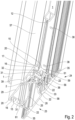
- FIG. 1 A sectional door leaf in a partial cross-section is shown in the Figure 1 in a perspective view with a horizontal profile 24 and a horizontal profile 23 arranged underneath.
- This schematic representation shows the interaction of two panel elements in frame structures for a sectional door leaf.
- These frame structures can consist of one or more subdivided fields that are filled with replaceable panes 45.
- Such panes 45 can be used as plate-shaped elements in a transparent or opaque design.
- Such panes 45 are held in position within the frame structure by replaceable retaining strips 1 that are attached to the inside of the building.
- the horizontal profile 23 has a convex design on the top and the corresponding horizontal profile 24 shown above has a concave area, whereby the two aluminum profile elements 23 and 24 virtually interlock in this position.
- a sealing element 33 is present in the profile 24, for example; other sealing options are also possible. This sealing element 33 performs a sealing function against moisture and wind loads etc. to the interior of the building in the closed position of the sectional door leaf, i.e. when the two panel elements 23, 24 are on top of one another.
- the panel elements consist of outer and inner sheet metal elements spaced apart by an insulating foam.
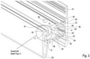
- the horizontal profile 23 is divided into two separate cavities in its cross-section. This means that there is an outer cavity and an inner cavity.
- the outer cavity is delimited to the outside of the building 26 by an outer leg 28 as part of the frame structure.
- insulating webs 22 are arranged on the top and bottom so that there is a closed outer cavity. There are no chambers or other self-contained additional cavities within this enclosed, outer cavity.
- the insulating webs 22 are made of a polyamide and have clamping sections 53 on their lateral ends, which were connected to the outer leg 28 made of aluminum and the intermediate web 25 made of aluminum in a force-fitting and form-fitting manner in a manufacturing process.
- the inner cavity which faces the interior of the building, has an inner leg 29 as part of the frame design, which has a profile offset 2 on the upper side, which merges into the intermediate web 25 in an upper end area.
- the lower end of the inner cavity between the intermediate web 25 and the inner profile is formed by a connecting section 61 with a receiving section 16 for a retaining strip 1.
- This lower connecting section 61 has a cross-sectional thickening compared to the other aluminum profile designs with an additional recess in the form of a connecting bearing for connecting the horizontal profiles 23 to a vertical profile 27 in a butt design.
- the inner cavity has molded material thickenings in the area in which holes 31 are present on the underside for butt connection with the vertical profile 27, which are used to connect the vertical profiles 27 via connecting elements 48. This makes the inner cavity a kind of assembly section with insulating properties and the outer cavity an exclusively insulating section in the frame design.
- a profile offset can be present on the outer leg 28 on the upper side before the insulating web 22 begins.
- the upper end of the horizontal profile 23 is thus provided with a protruding, convex end.
- an upper panel element interacts with the horizontal profile 23, which is in a frame design and contains the sealing element 33 for the sealing function against the insulating web 22, which is embedded in a sealing receptacle 36 of the horizontal profile 24.
- the horizontal profile 24 In order to ensure the sealing function of the two panel elements in the frame design with each other, there are projections on the horizontal profile 24 on each side in continuation of an inner leg 57 and the outer leg 30, which protrude onto the profile attachments with a clearance.
- the horizontal profile 24 is also, like the horizontal profile 23, equipped with an outer and inner cavity in cross-section.
- the outer cavity is formed by the outer leg 30 as part of a frame structure in connection with the intermediate web 56 spaced apart by the insulating webs 22.
- the inner cavity has the bore 31, through which the connecting bearing 32, which is also formed here, is accessible in order to connect the horizontal profile 24 to a vertical profile 27 via a butt joint formed at an angle of 90°.
- the horizontal profile 24 also has a receiving section 16 for the retaining strip 10.
- the profile thickening in the connecting section 61 is also present as a reinforcement in alignment with the bore 31, which is used for the connecting bearing 32 so that the horizontal profile 24 does not warp when the connection is made between a vertical profile 27 and horizontal profile 24.
- the Connecting section 61 serves to reinforce the horizontal profiles 23, 24 without increasing the weight of the aluminum profile elements.
- the inner cavity is designed differently in the horizontal profile 24 than in the horizontal profile 23. This is because the panel elements of the sectional door leaf will achieve a sealing function between two adjacent panel elements when the door is in the closed position.
- an additional chamber is provided at the bottom of the inner cavity, which ends in a rounded portion 39.
- the rounded portion 39 presses the existing sealing element 33, which is attached to the horizontal profile 24, against the convex profile attachment 2 of the underlying panel element with the horizontal profile 23.
- the cantilevered end leg 58 of the outer leg of the horizontal profile 24, opposite the profile offset 2 is carried out. This creates an essentially concave shape on the underside of the horizontal profile 24, into which the convex end region of the horizontal profile 23 dips.
- the butt joint is in the Figure 1 not shown.
- a substantially flat surface is created on the outside 26 of the sectional door leaf.
- the horizontal profile 24, for example has the cantilevered outer leg 30, which at the end dips into a shoulder 34 incorporated into the vertical profile 27.
- sealing receptacles 35 are provided in the cantilevered leg versions of the horizontal profiles 23 and 24 and at the end of the vertical profiles.
- the horizontal profile 24 in a cross-sectional view, shows the connecting bearing 32 with the reinforced material design in the connecting section 61 with the frame support 15.
- the design makes it possible for the butt connection between the vertical profile 27 and the horizontal profile 23 and 24 to provide a permanent, secure, force- and form-fitting connection without the need for additional components.
- the cross-sectional reinforcement represents a simple connection in the connecting section 61 with the guide 59 and no additional components need to be provided for stabilization when executing a frame corner connection, which would also lead to an increase in weight.
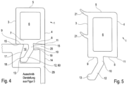
- the Figure 4 clarifies how the retaining strip 1 can be inserted within the open receiving space 16 with the protruding hook 12 and positioned against the plate-shaped element 45.
- the Figure 4 a first preferred embodiment of a retaining strip 1.
- the retaining strip 1 has a cavity 6 which is closed on all sides and which is closed on the outside of the door leaf by an outer wall 4 and on the inside by a contact side 3, and an upper intermediate leg 5 and a lower base 7.
- the contact side 3 comes into contact with the pane 45.
- the contact side 3 must apply the necessary pressure against the pane 45 or another plate-shaped element so that no water can penetrate from the outside between the contact side 3 and the pane 45.
- the retaining strip 1 can be achieved in particular by making the retaining strip 1 from an impact-resistant plastic with a high shore hardness, which nevertheless ensures a high contact pressure and thus large adhesion forces on the pane 45.
- the base 7 of the retaining strip 1 consists of a substantially straight support side 9, the adjoining hook 12 and a side adjoining it with a bevel 8 which ends in an outer support point 11.
- the support side 9 and the support point 11 are at the same height.
- the bevel 8, starting from the support point 11, is essentially in a range of 1° to 10°.
- the hook 12 is divided into a first section 10 and a second section 60.
- the first section 10 is set at an angle of between 91° and 110° with respect to the substantially straight support side 9. Following this first section 10, however, the second section 12 is again bevelled in the direction of the support side 6, whereby this angle, starting from the first section 10, is approximately between 40° and 50°.
- At the end of the second section 12 there is a protruding support point 13.
- the section 10 and the bend 60 of the hook 12 enter the receiving section 16.
- the support side 9 rests on the frame support 15 of the profiles 23, 24, 27 of the frame structure.
- the support point 11 has a further contact with the frame support 15. While the support point 11 is in contact with the leg 20, the section 10 of the hook 12 is laterally in contact with a counter bearing 19 of the frame structure in the Receiving section 16 in contact. Due to the inclination of the angle 60 of the hook 12, this comes into contact at the end within the receiving section 16 with an inner wall 17 on a support wall 18 via the support point 13.
- This type of construction ensures that the mounting strip 1 can be given a secure and permanent hold with the contact areas.
- the frame design has a frame profile outer side 14 on the outside, which is essentially aligned flush with the outer wall 4 of the holding strip 1 after the mounting strip 1 has been used.
- FIG. 5 another preferred embodiment of the mounting strip 1 is shown.
- additional sealing lips 21 are formed on the contact side 3.
- These sealing lips 21 have a lower Shore hardness than the retaining strip itself. This means that the two components of the retaining strip 1 can be manufactured in one operation using a 2K injection molding process, so that the contact side 3 can consist of a thermoplastic and the sealing lips of an elastomer.
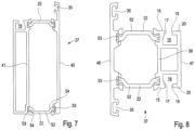
- FIG. 7 An exemplary preferred design of a vertical profile 27 is given by Figure 7
- an outer leg 40 which has a cantilevered area for a seal holder 35 at one end.
- the outer cavity is separated from the inner cavity by an intermediate web 41.
- the screw channels only have the functional task of entering into the butt joint.
- the outer leg 40 is again spaced from the intermediate web 41 by insulating webs 22.
- the force-fitting and form-fitting connection of the clamping sections 53 of the insulating webs 22 with the aluminum profile elements is again pointed out.
- the insulating webs 22 here have an essentially straight distance 52, to which offsets 54 are connected at the end. The offsets 54 then merge into the clamping sections 53.
- the profile design according to Figure 7 an inner cavity is present, which is formed on one side with the receiving section 16 for the retaining strip 1.
- a further, modified, preferred embodiment of a vertical profile 37 is shown.
- the vertical profile 37 is essentially formed by an outer leg 46 and insulating webs 22 connected to it, which are then connected at the end to an intermediate web 56.
- Such a vertical profile 37 is used when the frame design consists of several, i.e. self-contained fields for panes 45.
- This is also shown by the fact that the inner cavity is closed off on the outside by an inner leg 47.
- the inner leg 47 has the receiving sections 16 for the holding strips 1 and thus for the use of panes 45 on each of its two vertical sections.
- the outer leg 46 has projecting ends on both sides, each with a sealing receptacle 35.
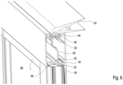
- FIG. 6 shows the upper end of a sectional door leaf.
- the design is based on Figure 6 used in such a way that a sealing receptacle 36 is connected on the top with a sealing foot 44 to a cantilevered upper end seal 43.
- an intermediate wall 55 separates the outer and inner cavity from one another.
- the lower section of a sectional door leaf, which has been provided with a frame, for example, is shown in the Figure 10 , whereby a floor end profile 49 is used here.
- This floor end profile 49 has a significantly higher profile than the other horizontally used profiles 23 and 24.
- the outer cavity is divided by several insulating webs 22 in order to achieve not only greater strength for the floor end profile 49 but also good thermal insulation at the same time.
- the floor seal 51 with its sealing foot 42 is inserted within a seal holder 50, which forms the lower end to a building-side support surface.
Landscapes
- Engineering & Computer Science (AREA)
- Civil Engineering (AREA)
- Structural Engineering (AREA)
- Wing Frames And Configurations (AREA)
- Securing Of Glass Panes Or The Like (AREA)
Priority Applications (1)
| Application Number | Priority Date | Filing Date | Title |
|---|---|---|---|
| EP24204059.0A EP4471248A3 (de) | 2022-05-27 | 2023-05-26 | Rahmenausbildung als teil eines paneelelementes für ein sektionaltorblatt |
Applications Claiming Priority (1)
| Application Number | Priority Date | Filing Date | Title |
|---|---|---|---|
| DE102022113450 | 2022-05-27 |
Related Child Applications (2)
| Application Number | Title | Priority Date | Filing Date |
|---|---|---|---|
| EP24204059.0A Division EP4471248A3 (de) | 2022-05-27 | 2023-05-26 | Rahmenausbildung als teil eines paneelelementes für ein sektionaltorblatt |
| EP24204059.0A Division-Into EP4471248A3 (de) | 2022-05-27 | 2023-05-26 | Rahmenausbildung als teil eines paneelelementes für ein sektionaltorblatt |
Publications (2)
| Publication Number | Publication Date |
|---|---|
| EP4299871A1 EP4299871A1 (de) | 2024-01-03 |
| EP4299871B1 true EP4299871B1 (de) | 2024-12-25 |
Family
ID=86604929
Family Applications (2)
| Application Number | Title | Priority Date | Filing Date |
|---|---|---|---|
| EP23175694.1A Active EP4299871B1 (de) | 2022-05-27 | 2023-05-26 | Rahmenausbildung als teil eines paneelelementes für ein sektionaltorblatt |
| EP24204059.0A Pending EP4471248A3 (de) | 2022-05-27 | 2023-05-26 | Rahmenausbildung als teil eines paneelelementes für ein sektionaltorblatt |
Family Applications After (1)
| Application Number | Title | Priority Date | Filing Date |
|---|---|---|---|
| EP24204059.0A Pending EP4471248A3 (de) | 2022-05-27 | 2023-05-26 | Rahmenausbildung als teil eines paneelelementes für ein sektionaltorblatt |
Country Status (5)
| Country | Link |
|---|---|
| EP (2) | EP4299871B1 (pl) |
| DE (2) | DE102023113971A1 (pl) |
| DK (1) | DK4299871T3 (pl) |
| ES (1) | ES3016643T3 (pl) |
| PL (1) | PL4299871T3 (pl) |
Citations (4)
| Publication number | Priority date | Publication date | Assignee | Title |
|---|---|---|---|---|
| GB2220024A (en) | 1988-06-22 | 1989-12-28 | Rehau Ag & Co | Glazing |
| DE102011105310A1 (de) | 2011-06-19 | 2012-12-20 | Marian Ionescu | Geschlossenes Profilsystem mit Dämmstoffkern |
| DE202018103416U1 (de) | 2018-05-22 | 2019-08-23 | Krispol Sp.z.o.o. | Sektionaltor mit anhubbarem Torblatt |
| DE202019105111U1 (de) | 2019-05-21 | 2020-08-24 | Krispol Sp.z.o.o. | Sektionaltor mit Hubflügel |
Family Cites Families (6)
| Publication number | Priority date | Publication date | Assignee | Title |
|---|---|---|---|---|
| GB2275957B (en) * | 1993-03-13 | 1996-10-23 | Deceuninck Ltd | Improvements in or relating to window assemblies |
| DE29900650U1 (de) * | 1999-01-19 | 1999-04-22 | TKI Technisch Konstruktive Interessengemeinschafts-GmbH Entwicklung- und Verwaltung von Aluminiumprofilsystemen, 63329 Egelsbach | Dichtungsanordnung für Fenster und Türen |
| DE10246932A1 (de) * | 2002-10-08 | 2004-04-22 | Aluplast Gmbh | Dichtung für ein Fensterprofil und Verfahren zu deren Herstellung |
| FR2897382B1 (fr) * | 2006-02-13 | 2008-04-25 | Stremler Soc Par Actions Simpl | "dispositif de verrouillage a au moins un point de condamnation" |
| DE102012010028A1 (de) | 2012-05-21 | 2013-11-21 | Hörmann KG Brockhagen | Rahmenanordnung für ein sektionaltorpaneel |
| WO2021209536A1 (en) * | 2020-04-16 | 2021-10-21 | Assa Abloy Entrance Systems Ab | Entrance system |
-
2023
- 2023-05-26 DE DE102023113971.1A patent/DE102023113971A1/de not_active Ceased
- 2023-05-26 EP EP23175694.1A patent/EP4299871B1/de active Active
- 2023-05-26 ES ES23175694T patent/ES3016643T3/es active Active
- 2023-05-26 PL PL23175694.1T patent/PL4299871T3/pl unknown
- 2023-05-26 EP EP24204059.0A patent/EP4471248A3/de active Pending
- 2023-05-26 DK DK23175694.1T patent/DK4299871T3/da active
- 2023-05-26 DE DE202023002954.6U patent/DE202023002954U1/de active Active
Patent Citations (4)
| Publication number | Priority date | Publication date | Assignee | Title |
|---|---|---|---|---|
| GB2220024A (en) | 1988-06-22 | 1989-12-28 | Rehau Ag & Co | Glazing |
| DE102011105310A1 (de) | 2011-06-19 | 2012-12-20 | Marian Ionescu | Geschlossenes Profilsystem mit Dämmstoffkern |
| DE202018103416U1 (de) | 2018-05-22 | 2019-08-23 | Krispol Sp.z.o.o. | Sektionaltor mit anhubbarem Torblatt |
| DE202019105111U1 (de) | 2019-05-21 | 2020-08-24 | Krispol Sp.z.o.o. | Sektionaltor mit Hubflügel |
Non-Patent Citations (8)
| Title |
|---|
| ANONYMOUS: "Das Sectionaltor-Programm in einzigartiger Programmbreite ", HÖRMANN DEUTSCHLAND - INDUSTRIETORE - INDUSTRIE- SECTIONALTORE, HOERMANN.DE, 20 July 2014 (2014-07-20), pages 1 - 1, XP093322343, Retrieved from the Internet <URL:https://web.archive.org/web/20140720171948/http://www.hoermann.de/industrietore/industrie-sectionaltore/> |
| ANONYMOUS: "Datenblatt insulbar®: insulbar® REG hergestellt aus TECATHERM 66 GF oder insulbar® RE hergestellt aus TECATHERM 66 GF RE ", DATENBLATT INSULBAR, ENSINGER GMBH, 1 September 2020 (2020-09-01), pages 1 - 1, XP093322376, Retrieved from the Internet <URL:https://www.insulbar.com> |
| ANONYMOUS: "Industrie-Sectionaltore Mit der innovativen Schlupftür ohne Stolperschwelle", KATALOG - INDUSTRIE-SECTIONALTORE, HÖRMANN, 1 March 2015 (2015-03-01), pages 1 - 88, XP093322365, Retrieved from the Internet <URL:https://web.archive.org/web/20150501015105/http://www.hoermann.de/fileadmin/_country/DE/kataloge/industrie_sectionaltore.pdf> |
| D1c - Auftragsbestätigung einer Sektionaltor-Bestellung durch die Firma Hörmann Austria Ges.mbH vom 09.10.2014 |
| D1d - Lieferschein des Sektionaltors an die Firma Hörmann Austria Ges.mbH vom 18.11.2014 |
| D1e - Auszüge zur Sektionaltor-Bestellung durch die Firma Hörmann Austria Ges.mbH aus dem SAP System der Einsprechenden |
| D1f - Technische Zeichnungen des an die Firma Hörmann Austria Ges.mbH gelieferten Sektionaltors |
| ENSINGER GMBH: "Ensinger: Thermisches Isolierprofil aus sortenreinem PA66-Recyclat zur Verbesserung der Ökobilanz von Gebäuden", PLASTICKER, NUFRINGEN, 27 June 2014 (2014-06-27), Nufringen, pages 1 - 2, XP093322369, Retrieved from the Internet <URL:https://plasticker.de/Kunststoff_News_22374_Ensinger_Thermisches_Isolierprofil_aus_sortenreinem_PA66_Recyclat_zur_Verbesserung_der_Oekobilanz_von_Gebaeuden> |
Also Published As
| Publication number | Publication date |
|---|---|
| PL4299871T3 (pl) | 2025-04-28 |
| EP4471248A2 (de) | 2024-12-04 |
| DK4299871T3 (da) | 2025-03-17 |
| ES3016643T3 (en) | 2025-05-09 |
| DE102023113971A1 (de) | 2023-11-30 |
| EP4471248A3 (de) | 2025-03-12 |
| EP4299871A1 (de) | 2024-01-03 |
| DE202023002954U1 (de) | 2025-03-08 |
Similar Documents
| Publication | Publication Date | Title |
|---|---|---|
| EP0616107B1 (de) | Stossverbindung von Hohlprofilabschnitten | |
| EP2666948B1 (de) | Rahmenanordnung für ein Sektionaltorpaneel | |
| DE3517861C2 (pl) | ||
| EP4283086B1 (de) | Rahmenausbildung als paneelelement für ein sektionaltorblatt | |
| EP1070820B1 (de) | Fenster | |
| EP4299871B1 (de) | Rahmenausbildung als teil eines paneelelementes für ein sektionaltorblatt | |
| EP0132842A2 (de) | Konstruktion zur gelenkigen Verbindung und Abdichtung zweier relativ gegeneinander schwenkbar beweglicher Tür- oder Torelemente | |
| DE1958087A1 (de) | Fenster oder Tuer | |
| EP1557519B1 (de) | Rahmenkörper aus einem hohlen, stranggepressten Kunststoffprofil für Fenster und Türen | |
| AT390473B (de) | Profilrahmen fuer schiebetueren oder -fenster | |
| DE60130085T2 (de) | Kunststoffflügel, sowie sein Herstellungsverfahren und zweiflügelige Öffnung, z.B. für ein Fenster | |
| EP2487313A1 (de) | Rahmenkonstruktion für ein Fenster oder eine Tür | |
| WO2010006626A1 (de) | Putzleiste | |
| DE20100618U1 (de) | Rahmenprofil | |
| DE19609624C2 (de) | Gebäudefenster und/oder Gebäudefenstertür | |
| EP4345240B1 (de) | Leichtmetallprofilverbindung | |
| DE202019104572U1 (de) | Profilverbinder zur Verbindung von Zargenprofilen und Anordnung damit | |
| DE102019108109A1 (de) | Universeller Schwellenverbinder mit Wechselelement | |
| DE102008047642A1 (de) | Tür | |
| EP2072744A2 (de) | Zargenprofil für eine Hebe-Schiebetür | |
| DE3301324A1 (de) | Verbesserungen bei rahmenteilen fuer fenster, tueren und anderen rahmenkonstruktionen | |
| DE202025105287U1 (de) | Verbindung zwischen einem Pfosten und einem Riegel, Konstruktion umfassend mindestens einen Riegel und mindestens einen Pfosten verbunden durch eine Verbindung | |
| EP4435223A1 (de) | Verfahren zur herstellung eines türblattes, montageelement und deckplattenbaugruppe dafür | |
| DE2157491A1 (de) | Rahmenteile zur Bildung von Rahmenecken | |
| DE102022106097A1 (de) | Türrahmen mit Bodenschwelle |
Legal Events
| Date | Code | Title | Description |
|---|---|---|---|
| PUAI | Public reference made under article 153(3) epc to a published international application that has entered the european phase |
Free format text: ORIGINAL CODE: 0009012 |
|
| STAA | Information on the status of an ep patent application or granted ep patent |
Free format text: STATUS: THE APPLICATION HAS BEEN PUBLISHED |
|
| AK | Designated contracting states |
Kind code of ref document: A1 Designated state(s): AL AT BE BG CH CY CZ DE DK EE ES FI FR GB GR HR HU IE IS IT LI LT LU LV MC ME MK MT NL NO PL PT RO RS SE SI SK SM TR |
|
| STAA | Information on the status of an ep patent application or granted ep patent |
Free format text: STATUS: REQUEST FOR EXAMINATION WAS MADE |
|
| STAA | Information on the status of an ep patent application or granted ep patent |
Free format text: STATUS: EXAMINATION IS IN PROGRESS |
|
| 17P | Request for examination filed |
Effective date: 20240702 |
|
| RBV | Designated contracting states (corrected) |
Designated state(s): AL AT BE BG CH CY CZ DE DK EE ES FI FR GB GR HR HU IE IS IT LI LT LU LV MC ME MK MT NL NO PL PT RO RS SE SI SK SM TR |
|
| 17Q | First examination report despatched |
Effective date: 20240731 |
|
| GRAP | Despatch of communication of intention to grant a patent |
Free format text: ORIGINAL CODE: EPIDOSNIGR1 |
|
| STAA | Information on the status of an ep patent application or granted ep patent |
Free format text: STATUS: GRANT OF PATENT IS INTENDED |
|
| INTG | Intention to grant announced |
Effective date: 20240905 |
|
| RIN1 | Information on inventor provided before grant (corrected) |
Inventor name: PANNEKOEK, DENNIS |
|
| GRAS | Grant fee paid |
Free format text: ORIGINAL CODE: EPIDOSNIGR3 |
|
| GRAA | (expected) grant |
Free format text: ORIGINAL CODE: 0009210 |
|
| STAA | Information on the status of an ep patent application or granted ep patent |
Free format text: STATUS: THE PATENT HAS BEEN GRANTED |
|
| AK | Designated contracting states |
Kind code of ref document: B1 Designated state(s): AL AT BE BG CH CY CZ DE DK EE ES FI FR GB GR HR HU IE IS IT LI LT LU LV MC ME MK MT NL NO PL PT RO RS SE SI SK SM TR |
|
| REG | Reference to a national code |
Ref country code: GB Ref legal event code: FG4D Free format text: NOT ENGLISH |
|
| REG | Reference to a national code |
Ref country code: CH Ref legal event code: EP |
|
| REG | Reference to a national code |
Ref country code: DE Ref legal event code: R096 Ref document number: 502023000423 Country of ref document: DE |
|
| REG | Reference to a national code |
Ref country code: IE Ref legal event code: FG4D Free format text: LANGUAGE OF EP DOCUMENT: GERMAN |
|
| REG | Reference to a national code |
Ref country code: SE Ref legal event code: TRGR |
|
| REG | Reference to a national code |
Ref country code: DK Ref legal event code: T3 Effective date: 20250312 |
|
| REG | Reference to a national code |
Ref country code: NL Ref legal event code: FP |
|
| REG | Reference to a national code |
Ref country code: LT Ref legal event code: MG9D |
|
| PG25 | Lapsed in a contracting state [announced via postgrant information from national office to epo] |
Ref country code: HR Free format text: LAPSE BECAUSE OF FAILURE TO SUBMIT A TRANSLATION OF THE DESCRIPTION OR TO PAY THE FEE WITHIN THE PRESCRIBED TIME-LIMIT Effective date: 20241225 |
|
| PG25 | Lapsed in a contracting state [announced via postgrant information from national office to epo] |
Ref country code: FI Free format text: LAPSE BECAUSE OF FAILURE TO SUBMIT A TRANSLATION OF THE DESCRIPTION OR TO PAY THE FEE WITHIN THE PRESCRIBED TIME-LIMIT Effective date: 20241225 |
|
| PG25 | Lapsed in a contracting state [announced via postgrant information from national office to epo] |
Ref country code: BG Free format text: LAPSE BECAUSE OF FAILURE TO SUBMIT A TRANSLATION OF THE DESCRIPTION OR TO PAY THE FEE WITHIN THE PRESCRIBED TIME-LIMIT Effective date: 20241225 |
|
| PG25 | Lapsed in a contracting state [announced via postgrant information from national office to epo] |
Ref country code: GR Free format text: LAPSE BECAUSE OF FAILURE TO SUBMIT A TRANSLATION OF THE DESCRIPTION OR TO PAY THE FEE WITHIN THE PRESCRIBED TIME-LIMIT Effective date: 20250326 Ref country code: LV Free format text: LAPSE BECAUSE OF FAILURE TO SUBMIT A TRANSLATION OF THE DESCRIPTION OR TO PAY THE FEE WITHIN THE PRESCRIBED TIME-LIMIT Effective date: 20241225 |
|
| PG25 | Lapsed in a contracting state [announced via postgrant information from national office to epo] |
Ref country code: RS Free format text: LAPSE BECAUSE OF FAILURE TO SUBMIT A TRANSLATION OF THE DESCRIPTION OR TO PAY THE FEE WITHIN THE PRESCRIBED TIME-LIMIT Effective date: 20250325 |
|
| REG | Reference to a national code |
Ref country code: ES Ref legal event code: FG2A Ref document number: 3016643 Country of ref document: ES Kind code of ref document: T3 Effective date: 20250509 |
|
| PG25 | Lapsed in a contracting state [announced via postgrant information from national office to epo] |
Ref country code: SM Free format text: LAPSE BECAUSE OF FAILURE TO SUBMIT A TRANSLATION OF THE DESCRIPTION OR TO PAY THE FEE WITHIN THE PRESCRIBED TIME-LIMIT Effective date: 20241225 |
|
| PGFP | Annual fee paid to national office [announced via postgrant information from national office to epo] |
Ref country code: DE Payment date: 20250521 Year of fee payment: 3 Ref country code: PL Payment date: 20250515 Year of fee payment: 3 |
|
| PGFP | Annual fee paid to national office [announced via postgrant information from national office to epo] |
Ref country code: DK Payment date: 20250526 Year of fee payment: 3 |
|
| PG25 | Lapsed in a contracting state [announced via postgrant information from national office to epo] |
Ref country code: IS Free format text: LAPSE BECAUSE OF FAILURE TO SUBMIT A TRANSLATION OF THE DESCRIPTION OR TO PAY THE FEE WITHIN THE PRESCRIBED TIME-LIMIT Effective date: 20250425 |
|
| PGFP | Annual fee paid to national office [announced via postgrant information from national office to epo] |
Ref country code: NO Payment date: 20250523 Year of fee payment: 3 |
|
| PGFP | Annual fee paid to national office [announced via postgrant information from national office to epo] |
Ref country code: BE Payment date: 20250521 Year of fee payment: 3 |
|
| PG25 | Lapsed in a contracting state [announced via postgrant information from national office to epo] |
Ref country code: PT Free format text: LAPSE BECAUSE OF FAILURE TO SUBMIT A TRANSLATION OF THE DESCRIPTION OR TO PAY THE FEE WITHIN THE PRESCRIBED TIME-LIMIT Effective date: 20250428 |
|
| PG25 | Lapsed in a contracting state [announced via postgrant information from national office to epo] |
Ref country code: EE Free format text: LAPSE BECAUSE OF FAILURE TO SUBMIT A TRANSLATION OF THE DESCRIPTION OR TO PAY THE FEE WITHIN THE PRESCRIBED TIME-LIMIT Effective date: 20241225 |
|
| PGFP | Annual fee paid to national office [announced via postgrant information from national office to epo] |
Ref country code: FR Payment date: 20250528 Year of fee payment: 3 |
|
| PG25 | Lapsed in a contracting state [announced via postgrant information from national office to epo] |
Ref country code: RO Free format text: LAPSE BECAUSE OF FAILURE TO SUBMIT A TRANSLATION OF THE DESCRIPTION OR TO PAY THE FEE WITHIN THE PRESCRIBED TIME-LIMIT Effective date: 20241225 |
|
| PGFP | Annual fee paid to national office [announced via postgrant information from national office to epo] |
Ref country code: AT Payment date: 20250721 Year of fee payment: 3 |
|
| PG25 | Lapsed in a contracting state [announced via postgrant information from national office to epo] |
Ref country code: SK Free format text: LAPSE BECAUSE OF FAILURE TO SUBMIT A TRANSLATION OF THE DESCRIPTION OR TO PAY THE FEE WITHIN THE PRESCRIBED TIME-LIMIT Effective date: 20241225 |
|
| PGFP | Annual fee paid to national office [announced via postgrant information from national office to epo] |
Ref country code: CZ Payment date: 20250520 Year of fee payment: 3 |
|
| PG25 | Lapsed in a contracting state [announced via postgrant information from national office to epo] |
Ref country code: IT Free format text: LAPSE BECAUSE OF FAILURE TO SUBMIT A TRANSLATION OF THE DESCRIPTION OR TO PAY THE FEE WITHIN THE PRESCRIBED TIME-LIMIT Effective date: 20241225 |
|
| PGFP | Annual fee paid to national office [announced via postgrant information from national office to epo] |
Ref country code: SE Payment date: 20250521 Year of fee payment: 3 |
|
| REG | Reference to a national code |
Ref country code: DE Ref legal event code: R026 Ref document number: 502023000423 Country of ref document: DE |
|
| PLBI | Opposition filed |
Free format text: ORIGINAL CODE: 0009260 |
|
| PLAX | Notice of opposition and request to file observation + time limit sent |
Free format text: ORIGINAL CODE: EPIDOSNOBS2 |
|
| PGFP | Annual fee paid to national office [announced via postgrant information from national office to epo] |
Ref country code: ES Payment date: 20250630 Year of fee payment: 3 |
|
| 26 | Opposition filed |
Opponent name: HOERMANN KG BROCKHAGEN Effective date: 20250925 |
|
| PG25 | Lapsed in a contracting state [announced via postgrant information from national office to epo] |
Ref country code: LU Free format text: LAPSE BECAUSE OF NON-PAYMENT OF DUE FEES Effective date: 20250526 |