EP4471248A2 - Rahmenausbildung als teil eines paneelelementes für ein sektionaltorblatt - Google Patents
Rahmenausbildung als teil eines paneelelementes für ein sektionaltorblatt Download PDFInfo
- Publication number
- EP4471248A2 EP4471248A2 EP24204059.0A EP24204059A EP4471248A2 EP 4471248 A2 EP4471248 A2 EP 4471248A2 EP 24204059 A EP24204059 A EP 24204059A EP 4471248 A2 EP4471248 A2 EP 4471248A2
- Authority
- EP
- European Patent Office
- Prior art keywords
- profile elements
- aluminum profile
- section
- elements
- horizontal
- Prior art date
- Legal status (The legal status is an assumption and is not a legal conclusion. Google has not performed a legal analysis and makes no representation as to the accuracy of the status listed.)
- Pending
Links
Images


Classifications
-
- E—FIXED CONSTRUCTIONS
- E06—DOORS, WINDOWS, SHUTTERS, OR ROLLER BLINDS IN GENERAL; LADDERS
- E06B—FIXED OR MOVABLE CLOSURES FOR OPENINGS IN BUILDINGS, VEHICLES, FENCES OR LIKE ENCLOSURES IN GENERAL, e.g. DOORS, WINDOWS, BLINDS, GATES
- E06B3/00—Window sashes, door leaves, or like elements for closing wall or like openings; Layout of fixed or moving closures, e.g. windows in wall or like openings; Features of rigidly-mounted outer frames relating to the mounting of wing frames
- E06B3/32—Arrangements of wings characterised by the manner of movement; Arrangements of movable wings in openings; Features of wings or frames relating solely to the manner of movement of the wing
- E06B3/48—Wings connected at their edges, e.g. foldable wings
- E06B3/485—Sectional doors
-
- E—FIXED CONSTRUCTIONS
- E06—DOORS, WINDOWS, SHUTTERS, OR ROLLER BLINDS IN GENERAL; LADDERS
- E06B—FIXED OR MOVABLE CLOSURES FOR OPENINGS IN BUILDINGS, VEHICLES, FENCES OR LIKE ENCLOSURES IN GENERAL, e.g. DOORS, WINDOWS, BLINDS, GATES
- E06B3/00—Window sashes, door leaves, or like elements for closing wall or like openings; Layout of fixed or moving closures, e.g. windows in wall or like openings; Features of rigidly-mounted outer frames relating to the mounting of wing frames
- E06B3/04—Wing frames not characterised by the manner of movement
- E06B3/263—Frames with special provision for insulation
- E06B3/26301—Frames with special provision for insulation with prefabricated insulating strips between two metal section members
- E06B3/26303—Frames with special provision for insulation with prefabricated insulating strips between two metal section members with thin strips, e.g. defining a hollow space between the metal section members
-
- E—FIXED CONSTRUCTIONS
- E06—DOORS, WINDOWS, SHUTTERS, OR ROLLER BLINDS IN GENERAL; LADDERS
- E06B—FIXED OR MOVABLE CLOSURES FOR OPENINGS IN BUILDINGS, VEHICLES, FENCES OR LIKE ENCLOSURES IN GENERAL, e.g. DOORS, WINDOWS, BLINDS, GATES
- E06B3/00—Window sashes, door leaves, or like elements for closing wall or like openings; Layout of fixed or moving closures, e.g. windows in wall or like openings; Features of rigidly-mounted outer frames relating to the mounting of wing frames
- E06B3/04—Wing frames not characterised by the manner of movement
- E06B3/263—Frames with special provision for insulation
- E06B3/26301—Frames with special provision for insulation with prefabricated insulating strips between two metal section members
- E06B3/26305—Connection details
- E06B3/26307—Insulating strips and metal section members both having L-shaped ribs, the engagement being made by a movement transversal to the plane of the strips
-
- E—FIXED CONSTRUCTIONS
- E06—DOORS, WINDOWS, SHUTTERS, OR ROLLER BLINDS IN GENERAL; LADDERS
- E06B—FIXED OR MOVABLE CLOSURES FOR OPENINGS IN BUILDINGS, VEHICLES, FENCES OR LIKE ENCLOSURES IN GENERAL, e.g. DOORS, WINDOWS, BLINDS, GATES
- E06B3/00—Window sashes, door leaves, or like elements for closing wall or like openings; Layout of fixed or moving closures, e.g. windows in wall or like openings; Features of rigidly-mounted outer frames relating to the mounting of wing frames
- E06B3/54—Fixing of glass panes or like plates
- E06B3/58—Fixing of glass panes or like plates by means of borders, cleats, or the like
- E06B3/5807—Fixing of glass panes or like plates by means of borders, cleats, or the like not adjustable
- E06B3/5821—Fixing of glass panes or like plates by means of borders, cleats, or the like not adjustable hooked on or in the frame member, fixed by clips or otherwise elastically fixed
-
- E—FIXED CONSTRUCTIONS
- E06—DOORS, WINDOWS, SHUTTERS, OR ROLLER BLINDS IN GENERAL; LADDERS
- E06B—FIXED OR MOVABLE CLOSURES FOR OPENINGS IN BUILDINGS, VEHICLES, FENCES OR LIKE ENCLOSURES IN GENERAL, e.g. DOORS, WINDOWS, BLINDS, GATES
- E06B3/00—Window sashes, door leaves, or like elements for closing wall or like openings; Layout of fixed or moving closures, e.g. windows in wall or like openings; Features of rigidly-mounted outer frames relating to the mounting of wing frames
- E06B3/96—Corner joints or edge joints for windows, doors, or the like frames or wings
- E06B3/9632—Corner joints or edge joints for windows, doors, or the like frames or wings between a jamb and the threshold or sill of window or door frames
-
- E—FIXED CONSTRUCTIONS
- E06—DOORS, WINDOWS, SHUTTERS, OR ROLLER BLINDS IN GENERAL; LADDERS
- E06B—FIXED OR MOVABLE CLOSURES FOR OPENINGS IN BUILDINGS, VEHICLES, FENCES OR LIKE ENCLOSURES IN GENERAL, e.g. DOORS, WINDOWS, BLINDS, GATES
- E06B3/00—Window sashes, door leaves, or like elements for closing wall or like openings; Layout of fixed or moving closures, e.g. windows in wall or like openings; Features of rigidly-mounted outer frames relating to the mounting of wing frames
- E06B3/96—Corner joints or edge joints for windows, doors, or the like frames or wings
- E06B3/9636—Corner joints or edge joints for windows, doors, or the like frames or wings for frame members having longitudinal screw receiving channels
-
- E—FIXED CONSTRUCTIONS
- E06—DOORS, WINDOWS, SHUTTERS, OR ROLLER BLINDS IN GENERAL; LADDERS
- E06B—FIXED OR MOVABLE CLOSURES FOR OPENINGS IN BUILDINGS, VEHICLES, FENCES OR LIKE ENCLOSURES IN GENERAL, e.g. DOORS, WINDOWS, BLINDS, GATES
- E06B7/00—Special arrangements or measures in connection with doors or windows
- E06B7/16—Sealing arrangements on wings or parts co-operating with the wings
- E06B7/22—Sealing arrangements on wings or parts co-operating with the wings by means of elastic edgings, e.g. elastic rubber tubes; by means of resilient edgings, e.g. felt or plush strips, resilient metal strips
- E06B7/23—Plastic, sponge rubber, or like strips or tubes
- E06B7/2305—Plastic, sponge rubber, or like strips or tubes with an integrally formed part for fixing the edging
- E06B7/2307—Plastic, sponge rubber, or like strips or tubes with an integrally formed part for fixing the edging with a single sealing-line or -plane between the wing and the part co-operating with the wing
- E06B7/2309—Plastic, sponge rubber, or like strips or tubes with an integrally formed part for fixing the edging with a single sealing-line or -plane between the wing and the part co-operating with the wing with a hollow sealing part
-
- E—FIXED CONSTRUCTIONS
- E06—DOORS, WINDOWS, SHUTTERS, OR ROLLER BLINDS IN GENERAL; LADDERS
- E06B—FIXED OR MOVABLE CLOSURES FOR OPENINGS IN BUILDINGS, VEHICLES, FENCES OR LIKE ENCLOSURES IN GENERAL, e.g. DOORS, WINDOWS, BLINDS, GATES
- E06B7/00—Special arrangements or measures in connection with doors or windows
- E06B7/16—Sealing arrangements on wings or parts co-operating with the wings
- E06B7/22—Sealing arrangements on wings or parts co-operating with the wings by means of elastic edgings, e.g. elastic rubber tubes; by means of resilient edgings, e.g. felt or plush strips, resilient metal strips
- E06B7/23—Plastic, sponge rubber, or like strips or tubes
- E06B7/2305—Plastic, sponge rubber, or like strips or tubes with an integrally formed part for fixing the edging
- E06B7/2312—Plastic, sponge rubber, or like strips or tubes with an integrally formed part for fixing the edging with two or more sealing-lines or -planes between the wing and part co-operating with the wing
-
- E—FIXED CONSTRUCTIONS
- E06—DOORS, WINDOWS, SHUTTERS, OR ROLLER BLINDS IN GENERAL; LADDERS
- E06B—FIXED OR MOVABLE CLOSURES FOR OPENINGS IN BUILDINGS, VEHICLES, FENCES OR LIKE ENCLOSURES IN GENERAL, e.g. DOORS, WINDOWS, BLINDS, GATES
- E06B3/00—Window sashes, door leaves, or like elements for closing wall or like openings; Layout of fixed or moving closures, e.g. windows in wall or like openings; Features of rigidly-mounted outer frames relating to the mounting of wing frames
- E06B3/04—Wing frames not characterised by the manner of movement
- E06B3/263—Frames with special provision for insulation
- E06B2003/26349—Details of insulating strips
- E06B2003/2635—Specific form characteristics
- E06B2003/26358—Specific form characteristics stepped or undulated
-
- E—FIXED CONSTRUCTIONS
- E06—DOORS, WINDOWS, SHUTTERS, OR ROLLER BLINDS IN GENERAL; LADDERS
- E06B—FIXED OR MOVABLE CLOSURES FOR OPENINGS IN BUILDINGS, VEHICLES, FENCES OR LIKE ENCLOSURES IN GENERAL, e.g. DOORS, WINDOWS, BLINDS, GATES
- E06B3/00—Window sashes, door leaves, or like elements for closing wall or like openings; Layout of fixed or moving closures, e.g. windows in wall or like openings; Features of rigidly-mounted outer frames relating to the mounting of wing frames
- E06B3/04—Wing frames not characterised by the manner of movement
- E06B3/263—Frames with special provision for insulation
- E06B2003/26349—Details of insulating strips
- E06B2003/2635—Specific form characteristics
- E06B2003/26361—Openings, incisions or indents
-
- E—FIXED CONSTRUCTIONS
- E06—DOORS, WINDOWS, SHUTTERS, OR ROLLER BLINDS IN GENERAL; LADDERS
- E06B—FIXED OR MOVABLE CLOSURES FOR OPENINGS IN BUILDINGS, VEHICLES, FENCES OR LIKE ENCLOSURES IN GENERAL, e.g. DOORS, WINDOWS, BLINDS, GATES
- E06B3/00—Window sashes, door leaves, or like elements for closing wall or like openings; Layout of fixed or moving closures, e.g. windows in wall or like openings; Features of rigidly-mounted outer frames relating to the mounting of wing frames
- E06B3/04—Wing frames not characterised by the manner of movement
- E06B3/263—Frames with special provision for insulation
- E06B2003/26349—Details of insulating strips
- E06B2003/26369—Specific material characteristics
- E06B2003/2637—Specific material characteristics reinforced
-
- E—FIXED CONSTRUCTIONS
- E06—DOORS, WINDOWS, SHUTTERS, OR ROLLER BLINDS IN GENERAL; LADDERS
- E06B—FIXED OR MOVABLE CLOSURES FOR OPENINGS IN BUILDINGS, VEHICLES, FENCES OR LIKE ENCLOSURES IN GENERAL, e.g. DOORS, WINDOWS, BLINDS, GATES
- E06B3/00—Window sashes, door leaves, or like elements for closing wall or like openings; Layout of fixed or moving closures, e.g. windows in wall or like openings; Features of rigidly-mounted outer frames relating to the mounting of wing frames
- E06B3/70—Door leaves
- E06B2003/7044—Garage doors
-
- E—FIXED CONSTRUCTIONS
- E06—DOORS, WINDOWS, SHUTTERS, OR ROLLER BLINDS IN GENERAL; LADDERS
- E06B—FIXED OR MOVABLE CLOSURES FOR OPENINGS IN BUILDINGS, VEHICLES, FENCES OR LIKE ENCLOSURES IN GENERAL, e.g. DOORS, WINDOWS, BLINDS, GATES
- E06B3/00—Window sashes, door leaves, or like elements for closing wall or like openings; Layout of fixed or moving closures, e.g. windows in wall or like openings; Features of rigidly-mounted outer frames relating to the mounting of wing frames
- E06B3/54—Fixing of glass panes or like plates
- E06B3/58—Fixing of glass panes or like plates by means of borders, cleats, or the like
- E06B3/5807—Fixing of glass panes or like plates by means of borders, cleats, or the like not adjustable
- E06B3/5842—Fixing of glass panes or like plates by means of borders, cleats, or the like not adjustable fixed by a tongue-and-groove or mortise-and-tenon connection substantially parallel to the pane
Definitions
- the invention relates to a frame structure as part of a panel element for a sectional door leaf, which consists of several panel elements that are connected to one another by hinges.
- the sectional door leaf is guided in lateral guides so that it can be moved.
- the frame structure consists of horizontal and vertical aluminum profile elements that are connected to one another, with the aluminum profile elements being provided with insulating bars that create a thermal separation between the outside and inside of a building.
- the DE 10 2012 010 028 A1 relates to a frame arrangement for producing a frame surrounding a filling for a building element, such as a sectional door panel, a door or the like, with an outer profile forming an outer side of the frame and an inner profile forming an inner side of the frame, wherein the profiles are preferably spaced apart from one another in a direction extending perpendicular to the outer side or inner side and are connected to one another via a connecting device made at least partially of a thermally insulating material with at least one boundary surface facing the filling, wherein a coupling device for producing a positive connection with a holding device designed to hold the filling is arranged on the boundary surface of the connecting device facing the filling.
- a sectional door is formed with a lifting wing with plate segments arranged one above the other and connected to each other in an articulated manner, with the joint axes perpendicular to the direction of movement of the sash.
- At least one of the sash segments is a rectangular frame with panel filling, consisting of hollow beams made of profiles, the upper beam of the frame having a convex edge at the top, the two beams being compatible with each other, and each of these beams consisting of two parallel and spaced closed profiles connected to each other by heat-insulating cross bridges.
- a sectional door with a liftable door leaf is from the DE 20 2018 103 416 U1 known.
- the door leaf consists of plate sections arranged one above the other and connected to one another in an articulated manner, the articulation axes being perpendicular to the direction of movement of the door leaf, which is determined by the lateral rail guides, and at least one of the door leaf sections having the shape of a square frame with plate filling, which consists of hollow beams formed by profiles, the upper beam of the frame having a convex edge at the top and the lower beam of the frame having a concave edge at the bottom, and the convex and concave contours of the edges of both beams matching one another, and each of these beams consists of two closed, parallel and spaced-apart profiles, which are connected to one another by transverse thermal insulation bridges, the cavity delimited by the side walls of the profiles and the bridges connecting them forming an intermediate chamber in each of these beams, and the lower beam of the frame consisting of profiles having at least one chamber and
- a sectional door system comprising a sectional door leaf with multiple horizontal sections that are movable between a vertical closed position and a horizontal, open or overhead position within a guide rail system provides the WO 2021/209536 A1
- the sectional door leaf has an inner and an outer door surface.
- the object of the invention is to create a frame structure as part of a panel element for sectional doors that ensures that the legal requirements for thermal insulation are met.
- a frame structure should be easy to manufacture, while at the same time providing sufficient longitudinal shear strength. It is important to ensure that such an assembly of the frame structure is easy to carry out.
- Aluminium profile elements which have an outer hollow section and an inner hollow section in cross-section, which are separated from each other.
- the outer hollow section serves to ensure thermal insulation.
- This hollow section is formed by an outer leg of the aluminium profile element through insulating webs on the top and bottom, which are connected to an inner intermediate web running in the direction of the aluminium profile element.
- the second, inner hollow section is directed towards the interior of the building and is formed by the intermediate web and the aluminium profile element sections connected to it towards the interior of the building.
- the inner leg of the The aluminum profile element can be connected directly or indirectly to the insulating intermediate webs. This design of the aluminum profile elements applies to both horizontal and vertical profile versions.
- the frame structure is intended as part of a panel element for sectional door leaves, it must be ensured that the frame structure is so stable at the top and bottom that the same sealing and interacting function is ensured with a conventional panel element of the same design arranged above or below.
- a conventional panel element of the same design arranged above or below.
- such frame structures have a convex shape on their top and a concave shape on their bottom. This type of construction ensures that the interaction of a frame structure with panel elements arranged above or below works without problems.
- This type of design also means that the same fittings can be used between a frame structure and a closed panel element in order to be able to carry out a hinged movement between them.
- the structural design of the aluminium profile elements into an inner and an outer hollow section in the cross-section results in a very effective division into an outer hollow section that serves exclusively for thermal insulation and an inner hollow section that also contributes to thermal insulation, but is also used to connect corner versions of the aluminium profile elements in a butt-joint design, i.e. there are no miter cuts.
- the outer hollow section has an outer leg that has no further reinforcement elements or chambers or projections formed on the inside.
- the intermediate web does not necessarily have a straight course between the inner and outer hollow sections, but can also take on other shapes.
- the outer hollow section is closed off on the top and bottom by the insulating bars.
- To connect the outer leg and the intermediate bar to the insulating bars these have fastening sections at the end that make it possible to permanently fasten the insulating bars in a different shape to aluminum profile elements in one manufacturing process.
- the insulating bars preferably have trapezoidal clamping sections at the end that are permanently pressed into the sections of the aluminum profile elements during the manufacturing process.
- polymers are used as the material.
- Polymers are ideally suited to forming such insulating bars. This is because polymers are characterized as a tough material with high strength and rigidity that can also be used in a wide temperature range from around -30°C to over +100°C. This is particularly important for sectional doors with a frame design, as very high temperatures can occur when the sun shines on the outer legs, but also very low temperatures in winter.
- the family of linear polymers with amide compounds is particularly suitable for this.
- the linear polymers can be provided with additives.
- Elongated glass fibers in the form of glass fiber reinforced polyamides have proven to be the preferred choice for the design and construction of insulating bars.
- the option of efficient production of rod materials for the insulating bars made of polyamide is cost-effective.
- the complexity of the geometry of the insulating bars with and without fiber reinforced polyamides has enormous rigidity and at the same time great elasticity.
- the water absorption of the insulating bars is fundamentally unavoidable, but can be considered minimal. and does not affect the dimensional stability of the frame design of the aluminum profile elements in any way.
- the inner hollow section of the aluminum profile elements can in principle also contribute to the thermal insulation of the profile design as a whole.
- this inner hollow section has the particular task of facilitating the connection between vertical and horizontal profile sections to form the frame.
- the inner hollow section has an essentially straight inner leg on the inside and the associated connecting sections, which are connected directly or indirectly to the intermediate web, for example, or can enable the inclusion of retaining strips for holding plate-shaped elements.
- connecting screws can be inserted into a profile to be connected as a butt connection.
- holes are provided through which the connection between two aluminum profile elements at an angle of 90° to each other can be made using reinforced connecting bearings. This enables a simple and permanent, cost-effective connection of two profile sections.
- a space for the retaining strips is formed over the connecting section between the inner leg and the intermediate web.
- a retaining strip can be made of plastic or light metal for reasons of weight.
- Such a retaining strip has a cavity enclosed on all sides by walls, which makes the retaining strip as a whole torsion-resistant. For assembly and disassembly in the event of damage to the fillings of the fields of view, it is necessary that the plate-shaped elements can be replaced quickly and easily.
- an impact-resistant plastic with a very high shore hardness is preferably used.
- the enclosed cavity has a base on the underside from which a protruding, spread-out hook extends. The retaining strip engages with this hook in a
- the retaining strip rests on a part of the aluminum profile element.
- the design of the hook is characterized by two different sections. A high prestress is to be created on the outside of the retaining strip compared to the plate-shaped element. It is necessary that only materials that are not subject to embrittlement are used for the retaining strip.
- the side on which the retaining strip is positioned against the plate-shaped element can be provided with sealing lips.
- Such a construction can be produced using a two-component technique. In an injection molding process, different hardnesses of a retaining strip are produced in one operation, but with strictly separate component areas. By using such additional sealing lips, an additional very good seal can be achieved between the retaining strip and the plate-shaped element.
- thermoplastic plus elastomer i.e. plastic and rubber, complex assembly work on the frame structure after inserting the plate-shaped element to ensure sufficient tightness can be avoided.
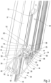
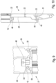
- FIG. 1 A sectional door leaf in a partial cross-section is shown in the Figure 1 in a perspective view with a horizontal profile 24 and a horizontal profile 23 arranged underneath.
- This schematic representation shows the interaction of two panel elements in frame structures for a sectional door leaf.
- These frame structures can consist of one or more subdivided fields that are filled with replaceable panes 45.
- Such panes 45 can be used as plate-shaped elements in a transparent or opaque design.
- Such panes 45 are held in position within the frame structure by replaceable retaining strips 1 that are attached to the inside of the building.
- the horizontal profile 23 has a convex design on the top and the corresponding horizontal profile 24 shown above has a concave area, whereby the two aluminum profile elements 23 and 24 virtually interlock in this position.
- a sealing element 33 is present in the profile 24, for example; other sealing options are also possible. This sealing element 33 performs a sealing function against moisture and wind loads etc. to the interior of the building in the closed position of the sectional door leaf, i.e. when the two panel elements 23, 24 are on top of each other.
- the panel elements consist of outer and inner sheet metal elements spaced apart by an insulating foam.
- the horizontal profile 23 is divided into two separate cavities in its cross-section. This means that there is an outer cavity and an inner cavity.
- the outer cavity is delimited to the outside of the building 26 by an outer leg 28 as part of the frame structure.
- insulating webs 22 are arranged on the top and bottom so that there is a closed outer cavity. There are no chambers or other self-contained additional cavities within this enclosed, outer cavity.
- the insulating webs 22 are made of a polyamide and have clamping sections 53 on their lateral ends, which were connected to the outer leg 28 made of aluminum and the intermediate web 25 made of aluminum in a force-fitting and form-fitting manner in a manufacturing process.
- the inner cavity which faces the interior of the building, has an inner leg 29 as part of the frame design, which has a profile offset 2 on the upper side, which merges into the intermediate web 25 in an upper end area.
- the lower end of the inner cavity between the intermediate web 25 and the inner profile is formed by a connecting section 61 with a receiving section 16 for a retaining strip 1.
- This lower connecting section 61 has a cross-sectional thickening compared to the other aluminum profile designs with an additional recess in the form of a connecting bearing for connecting the horizontal profiles 23 to a vertical profile 27 in a butt design.
- the inner cavity has molded material thickenings in the area in which holes 31 are present on the underside for butt connection with the vertical profile 27, which are used to connect the vertical profiles 27 via connecting elements 48. This makes the inner cavity quasi an assembly section with insulating properties and the outer cavity an exclusively insulating section in the frame design.
- a profile offset can be present on the outer leg 28 on the upper side before the insulating web 22 begins.
- the upper end of the horizontal profile 23 is thus provided with a protruding, convex end.
- an upper panel element interacts with the horizontal profile 23, which is in a frame design and contains the sealing element 33 for the sealing function against the insulating web 22, which is embedded in a sealing receptacle 36 of the horizontal profile 24.
- the horizontal profile 24 In order to ensure the sealing function of the two panel elements in the frame design with each other, there are projections on the horizontal profile 24 on each side in continuation of an inner leg 57 and the outer leg 30, which protrude onto the profile attachments with a clearance.
- the horizontal profile 24 is also, like the horizontal profile 23, equipped with an outer and inner cavity in cross-section.
- the outer cavity is formed by the outer leg 30 as part of a frame structure in connection with the intermediate web 56 spaced apart by the insulating webs 22.
- the inner cavity has the hole 31, through which the connecting bearing 32, which is also formed here, is accessible in order to connect the horizontal profile 24 to a vertical profile 27 via a butt joint formed at an angle of 90°.
- the horizontal profile 24 also has a receiving section 16 for the retaining strip 10.
- the profile thickening in the connecting section 61 is also present as a reinforcement in alignment with the bore 31, which is used for the connecting bearing 32 so that the horizontal profile 24 does not warp when the connection is made between a vertical profile 27 and horizontal profile 24.
- the Connecting section 61 serves to reinforce the horizontal profiles 23, 24 without increasing the weight of the aluminum profile elements.
- the inner cavity is designed differently in the horizontal profile 24 than in the horizontal profile 23. This is because the panel elements of the sectional door leaf will achieve a sealing function between two adjacent panel elements when the door is in the closed position.
- an additional chamber is provided at the bottom of the inner cavity, which ends in a rounded portion 39.
- the rounded portion 39 presses the existing sealing element 33, which is attached to the horizontal profile 24, against the convex profile attachment 2 of the underlying panel element with the horizontal profile 23.
- the cantilevered end leg 58 of the outer leg of the horizontal profile 24, opposite the profile offset 2 is carried out. This creates an essentially concave shape on the underside of the horizontal profile 24, into which the convex end region of the horizontal profile 23 dips.
- the butt joint is in the Figure 1 not shown.
- a substantially flat surface is created on the outside 26 of the sectional door leaf.
- the horizontal profile 24, for example has the cantilevered outer leg 30, which at the end dips into a shoulder 34 incorporated into the vertical profile 27.
- sealing receptacles 35 are provided in the cantilevered leg versions of the horizontal profiles 23 and 24 and at the end of the vertical profiles.
- the horizontal profile 24 in a cross-sectional view, shows the connecting bearing 32 with the reinforced material design in the connecting section 61 with the frame support 15.
- the design makes it possible for the butt connection between the vertical profile 27 and the horizontal profile 23 and 24 to provide a permanent, secure, force- and form-fitting connection without the need for additional components.
- the cross-sectional reinforcement represents a simple connection in the connecting section 61 with the guide 59 and no additional components need to be provided for stabilization when executing a frame corner connection, which would also lead to an increase in weight.
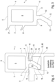
- the Figure 4 clarifies how the retaining strip 1 can be inserted within the open receiving space 16 with the protruding hook 12 and positioned against the plate-shaped element 45.
- the Figure 4 a first preferred embodiment of a retaining strip 1.
- the retaining strip 1 has a cavity 6 which is closed on all sides and which is closed on the outside of the door leaf by an outer wall 4 and on the inside by a contact side 3, and an upper intermediate leg 5 and a lower base 7.
- the contact side 3 comes into contact with the pane 45.
- the contact side 3 must apply the necessary pressure against the pane 45 or another plate-shaped element so that no water can penetrate from the outside between the contact side 3 and the pane 45.
- the retaining strip 1 can be achieved in particular by making the retaining strip 1 from an impact-resistant plastic with a high shore hardness, which nevertheless ensures a high contact pressure and thus large adhesion forces on the pane 45.
- the base 7 of the retaining strip 1 consists of a substantially straight support side 9, the adjoining hook 12 and an adjoining side with a bevel 8 which ends in an outer support point 11.
- the support side 9 and the support point 11 are at the same height.
- the bevel 8, starting from the support point 11, is essentially in a range of 1° to 10°.
- the hook 12 is divided into a first section 10 and a second section 60.
- the first section 10 is set at an angle of between 91° and 110° with respect to the substantially straight support side 9.
- the second section 12 is again bevelled in the direction of the support side 6, whereby this angle, starting from the first section 10, is approximately between 40° and 50°.
- At the end of the second section 12 there is a protruding support point 13.
- the section 10 and the bend 60 of the hook 12 enter the receiving section 16.
- the support side 9 rests on the frame support 15 of the profiles 23, 24, 27 of the frame structure.
- the support point 11 has a further contact with the frame support 15. While the support point 11 is in contact with the leg 20, the section 10 of the hook 12 is laterally in contact with a counter bearing 19 of the frame structure in the Receiving section 16 in contact. Due to the inclination of the angle 60 of the hook 12, this comes into contact at the end within the receiving section 16 with an inner wall 17 on a support wall 18 via the support point 13.
- This type of construction ensures that the mounting strip 1 can be given a secure and permanent hold with the contact areas.
- the frame design has a frame profile outer side 14 on the outside, which is essentially aligned flush with the outer wall 4 of the holding strip 1 after the mounting strip 1 has been used.
- FIG. 5 another preferred embodiment of the mounting strip 1 is shown.
- additional sealing lips 21 are formed on the contact side 3.
- These sealing lips 21 have a lower Shore hardness than the retaining strip itself. This means that the two components of the retaining strip 1 can be manufactured in one operation using a 2K injection molding process, so that the contact side 3 can consist of a thermoplastic and the sealing lips of an elastomer.
- FIG. 7 An exemplary preferred design of a vertical profile 27 is given by Figure 7
- an outer leg 40 which has a cantilevered area at one end for a seal holder 35.
- the outer cavity is separated from the inner cavity by an intermediate web 41.
- the screw channels only have the functional task of entering into the butt joint.
- the outer leg 40 is again spaced from the intermediate web 41 by insulating webs 22.
- the force-fitting and form-fitting connection of the clamping sections 53 of the insulating webs 22 with the aluminum profile elements is again pointed out.
- the insulating webs 22 here have an essentially straight distance 52, to which offsets 54 are connected at the end. The offsets 54 then merge into the clamping sections 53.
- the profile design according to Figure 7 an inner cavity is present, which is formed on one side with the receiving section 16 for the retaining strip 1.
- a further, modified, preferred embodiment of a vertical profile 37 is shown.
- the vertical profile 37 is essentially formed by an outer leg 46 and insulating webs 22 connected to it, which are then connected at the end to an intermediate web 56.
- Such a vertical profile 37 is used when the frame design consists of several, i.e. self-contained fields for panes 45.
- This is also shown by the fact that the inner cavity is closed off on the outside by an inner leg 47.
- the inner leg 47 has the receiving sections 16 for the holding strips 1 and thus for the use of panes 45 on each of its two vertical sections.
- the outer leg 46 has projecting ends on both sides, each with a sealing receptacle 35.
- FIG. 6 shows the upper end of a sectional door leaf.
- the design is based on Figure 6 used in such a way that a sealing receptacle 36 is connected on the top with a sealing foot 44 to a cantilevered upper end seal 43.
- an intermediate wall 55 separates the outer and inner cavity from one another.
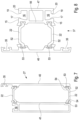
- the lower section of a sectional door leaf, which has been provided with a frame, for example, is shown in the Figure 10 , whereby a floor end profile 49 is used here.
- This floor end profile 49 has a significantly higher profile than the other horizontally used profiles 23 and 24.
- the outer cavity is divided by several insulating webs 22 in order to achieve not only greater strength for the floor end profile 49 but also good thermal insulation at the same time.
- the floor seal 51 with its sealing foot 42 is inserted within a seal holder 50, which forms the lower end to a building-side support surface.
Landscapes
- Engineering & Computer Science (AREA)
- Civil Engineering (AREA)
- Structural Engineering (AREA)
- Wing Frames And Configurations (AREA)
- Securing Of Glass Panes Or The Like (AREA)
Abstract
Description
- Die Erfindung betrifft eine Rahmenausbildung als Teil eines Paneelelementes für ein Sektionaltorblatt, das aus mehreren Paneelelementen besteht, die untereinander scharnierend miteinander verbunden sind. Das Sektionaltorblatt wird in seitlichen Führungen ortsveränderbar geführt. Die Rahmenausbildung besteht dabei aus horizontalen und vertikalen Aluminiumprofilelementen, die untereinander verbunden sind, wobei die Aluminiumprofilelemente mit Isolierstegen versehen sind, die eine thermische Trennung zwischen außerhalb und innerhalb eines Gebäudes bewirken.
- Die
DE 10 2012 010 028 A1 betrifft eine Rahmenanordnung zur Herstellung eines eine Füllung umlaufenden Rahmens für ein Bauelement, wie etwa ein Sektionaltorpaneel, eine Tür oder dergleichen mit einem eine Außenseite des Rahmens bildenden äußeren Profil und einem eine Innenseite des Rahmens bildenden inneren Profil, wobei die Profile sich vorzugsweise in einer senkrecht zur Außenseite, bzw. Innenseite erstreckenden Richtung voneinander beabstandet und über eine zumindest teilweise aus einem thermisch isolierenden Material beabstanden Verbindungseinrichtung mit mindestens einer der Füllung zugewandten Begrenzungsfläche miteinander verbunden sind, wobei an der der Füllung zugewandten Begrenzungsfläche der Verbindungseinrichtung eine zum Herstellen einer formschlüssigen Verbindung mit einer zum Halten der Füllung ausgelegten Halteeinrichtung dienenden Kopplungseinrichtung angeordnet ist. - In der
DE 20 2019 105 111 U1 wird ein Sektionaltor mit einem Hubflügel mit übereinander angeordneten und miteinander gelenkig verbundenen Plattensegmenten gebildet ist, wobei die Gelenkachsen senkrecht zur Bewegungsrichtung des Flügels stehen. Dabei ist mindestens eines der Flügelsegmente ein rechteckiger Rahmen mit Plattenfüllung, der aus Hohlbalken aus Profilen besteht, wobei der obere Balken des Rahmens oben einen konvexen Rand aufweist, die beiden Träger miteinander kompatibel sind, und jeder dieser Träger besteht aus zwei parallelen und beabstandeten geschlossenen Profilen, die durch wärmeisolierende Querbrücken miteinander verbunden sind. - Ein Sektionaltor mit einem anhubbaren Torblatt ist aus der
DE 20 2018 103 416 U1 bekannt. Dabei besteht das Torblatt aus übereinander angeordneten und gelenkig miteinander verbundenen Plattensektionen, wobei die Gelenkachsen senkrecht zur Bewegungsrichtung des Torblattes, die durch die seitlichen Schienenführungen bestimmt wird, liegen, und wobei mindestens eine der Torblattsektionen die Form eines viereckigen Rahmens mit Plattenfüllung hat, der aus Hohlbalken, die durch Profile gebildet werden, besteht, wobei der obere Balken des Rahmens einen konvexen Rand oben und der untere Balken des Rahmens einen konkaven Rand unten hat und die konvexen und konkaven Konturen der Ränder beider Balken zueinander passen und jeder dieser Balken aus zwei geschlossenen, parallel angeordneten und voneinander beabstandeten Profilen besteht, die durch querliegende Wärmedämmbrücken miteinander verbunden sind, wobei der Hohlraum, der von den Seitenwänden der Profile und den sie verbindenden Brücken begrenzt wird, in jedem dieser Balken eine Zwischenkammer bildet und wobei der untere Balken des Rahmens aus Profilen besteht, die mindestens eine Kammer haben, und der obere Balken aus Einkammerprofilen besteht, dabei ist jedes von den Profilen des unteren Balkens durch eine Quertrennwand in zwei übereinander liegende Kammern unterteilt. - Ein Sektionaltorsystem mit einem Sektionaltorblatt mit mehreren horizontalen Abschnitten, die zwischen einer vertikalen geschlossenen Position und einer horizontalen, geöffneten oder Überkopfposition innerhalb eines Führungsschienensystems bewegbar sind, gibt die
WO 2021/209536 A1 wieder. Dabei weist das Sektionaltorblatt eine innere und eine äußere Torfläche auf. - Die Aufgabe der Erfindung besteht darin, eine Rahmenausbildung als Teil eines Paneelelementes für Sektionaltore zu schaffen, die sicherstellt, dass die gesetzlichen Vorgaben zur Wärmedämmung eingehalten werden. Eine derartige Rahmenausbildung soll einfach herstellbar sein, wobei gleichzeitig eine ausreichende Längsschubfestigkeit gegeben sein muss. Dabei ist darauf zu achten, dass eine derartige Montage der Rahmenausbildung einfach ausführbar ist.
- Die Aufgabe der Erfindung wird durch die Merkmale des Anspruches 1 gelöst. Die sich anschließenden Unteransprüche geben dabei eine weitere Ausgestaltung des erfindungsgemäßen Gedankens wieder.
- Es werden Aluminiumprofilelemente verwendet, die im Querschnitt einen äußeren Hohlabschnitt und einen inneren Hohlabschnitt aufweisen, die untereinander getrennt sind. Der äußere Hohlabschnitt dienst zur Sicherstellung der Wärmedämmung. Dieser Hohlabschnitt wird von einem äußeren Außenschenkel des Aluminiumprofilelementes durch ober- und unterseitig vorhandene Isolierstege, die mit einem inneren, in Richtung des Aluminiumprofilelementes verlaufenden Zwischensteg verbunden sind, gebildet. Dadurch entsteht ein äußerer Hohlabschnitt, der sicherstellt, dass die notwendige Wärmebrücke, d.h. Trennung zwischen Innen und Außen eines Gebäudes, gewährleistet wird. Der zweite, innere Hohlabschnitt ist zum Innenraum des Gebäudes gerichtet und wird durch den Zwischensteg und mit diesem verbundenen Aluminiumprofilelementabschnitten zum Gebäudeinneren gebildet. Der Innenschenkel des Aluminiumprofilelementes kann dabei direkt oder indirekt mit den isolierenden Zwischenstegen verbunden werden. Diese Ausgestaltung der Aluminiumprofilelemente gilt sowohl für horizontal, als auch für vertikal verwendete Profilausführungen.
- Dadurch, dass die Rahmenausbildung als Teil eines Paneelelementes für Sektionaltorblätter bestimmt ist, muss hier sichergestellt werden, dass die Rahmenausbildung oben und unten so stabil ist, dass hier die gleiche abdichtende und zusammenwirkende Funktion mit einem darüber oder darunter angeordnetem gleichartig ausgebildetem herkömmlichen Paneelelement sichergestellt wird. Dafür weisen derartige Rahmenausbildungen an ihrer Oberseite eine konvexe Form und an ihrer Unterseite eine konkave Formgestaltung auf. Durch eine derartige Konstruktion ist sichergestellt, dass ein Zusammenwirken einer Rahmenausbildung mit darüber oder darunter angeordneten Paneelelementen problemlos funktioniert. Durch eine solche Ausführungsform können auch zwischen einer Rahmenausbildung und einem geschlossenen Paneelelement die gleichen Beschläge verwendet werden, um so eine scharnierende Bewegung untereinander ausführen zu können.
- Durch die konstruktive Gestaltung der Aluminiumprofilelemente in einen inneren und einen äußeren Hohlabschnitt im Querschnitt wird eine sehr effektive Aufteilung in einen ausschließlich der Wärmedämmung dienenden äußeren Hohlabschnitt und einen inneren Hohlabschnitt, der zwar auch zur Wärmedämmung beiträgt, aber auch zur Verbindung von Eckausführungen der Aluminiumprofilelemente in einer Stoßausführung untereinander, d.h., es sind keine Gehrungsschnitte vorhanden, verwendet wird.
- Der äußere Hohlabschnitt weist einen Außenschenkel auf, der innenseits keine weiteren Verstärkungselemente oder Kammern oder Vorsprünge angeformt hat. Der Zwischensteg weist nicht unbedingt einen geraden Verlauf zwischen den inneren und äußeren Hohlabschnitten auf, sondern kann auch andere Formen annehmen. Oberseits und unterseits ist der äußere Hohlabschnitt durch die Isolierstege abgeschlossen. Zur Verbindung zwischen dem Außenschenkel und dem Zwischensteg mit den Isolierstegen weisen diese endseits Befestigungsabschnitte auf, die es ermöglichen, in einem Fertigungsprozess eine dauerhafte Befestigung der Isolierstege in einer unterschiedlichen Formgestaltung bei Aluminiumprofilelementen auszuführen. Dafür weisen die Isolierstege endseits vorzugsweise etwa trapezförmige Einspannabschnitte auf, die in dem Fertigungsprozess mit den Abschnitten der Aluminiumprofilelemente dauerhaft verpresst werden. Um eine große Festigkeit und auch gleichzeitig Steifigkeit bei den verwendeten Isolierstegen zu erzielen, wird auf die Verwendung von Polymeren als Werkstoff zurückgegriffen. Polymere sind bestens geeignet, um derartige Isolierstege auszubilden. Denn die Polymere zeichnen sich als ein zähes Material mit hoher Festigkeit und Steifigkeit aus, die auch in einem großen Temperaturbereich von etwa -30°C bis über +100°C Verwendung finden können. Dieses ist insbesondere bei Sektionaltoren mit einer Rahmengestaltung von großer Bedeutung, da bei einer Sonneneinstrahlung auf die Außenschenkel sehr hohe, im Winter aber auch sehr niedrige Temperaturen möglich sind. Dafür eignet sich insbesondere die Familie der linearen Polymere mit Amidverbindungen.
- Um eine noch höhere Formbeständigkeit und Belastbarkeit der Isolierstege zu erzielen, können die linearen Polymere mit Zusatzstoffen versehen werden. Dabei haben sich vorzugsweise langgestreckte Glasfasern in Form von glasfaserverstärkten Polyamiden bei der Gestaltung und Ausführung von Isolierstegen bewährt. Die Möglichkeit einer rationellen Fertigung von Stangenmaterialien für die Isolierstege aus dem Werkstoff Polyamid ist kostengünstig ausführbar. Die Komplexität der Geometrie der Isolierstege mit und ohne faserverstärkte Polyamide haben eine enorme Steifigkeit bei gleichzeitiger großer Elastizität. Die Wasseraufnahme der Isolierstege ist grundsätzlich nicht zu vermeiden, kann aber als minimal bezeichnet werden und beeinträchtigt die Formstabilität der Rahmenausbildung der Aluminiumprofilelemente in keinster Weise.
- Der innere Hohlabschnitt der Aluminiumprofilelemente kann grundsätzlich auch zur Wärmedämmung der Profilausbildung insgesamt beitragen. Doch fällt diesem inneren Hohlabschnitt insbesondere die Aufgabe zu, die Verbindung zwischen vertikalen und horizontalen Profilabschnitten zur Rahmenbildung zu erleichtern. Der innere Hohlabschnitt weist auf der Innenseite einen im Wesentlichen geraden Innenschenkel und die damit verbundenen Verbindungsabschnitte auf, die beispielsweise direkt oder indirekt mit dem Zwischensteg verbunden sind oder die Aufnahme von Halteleisten zur Halterung von plattenförmigen Elementen ermöglichen können. Ferner können hier Verbindungsschrauben in ein zu verbindendes Profil als Stoßverbindung einbracht werden. Dafür sind Bohrungen vorhanden, über die mit verstärkten Verbindungslagern die Verbindung zwischen zwei im Winkel von 90° zueinanderstehenden Aluminiumprofilelementen ausgeführt werden kann. Dadurch ist eine einfache und dauerhafte kostengünstige Verbindung von zwei Profilabschnitten möglich.
- Über den Verbindungsabschnitt zwischen dem Innenschenkel und dem Zwischensteg wird ein Aufnahmeraum für die Halteleisten ausgebildet. Beispielsweise kann eine derartige Halteleiste aus Gewichtsgründen aus Kunststoff oder aber auch aus Leichtmetall bestehen. Eine solche Halteleiste weist einen durch Wandungen allseits umschlossenen Hohlraum auf, der dadurch die Halteleiste insgesamt verwindungssteif macht. Zur Montage und auch Demontage bei einer Beschädigung der Ausfüllungen der Sichtfelder ist es notwendig, dass die plattenförmigen Elemente schnell und einfach ausgewechselt werden können. Bei der Ausführung der Halteleiste in Kunststoff wird vorzugsweise ein schlagzäher Kunststoff mit einer sehr großen Shorehärte verwendet. Der umschlossene Hohlraum weist unterseitig eine Basis auf, von der ein vorstehender, abgespreizter Haken abgeht. Die Halteleiste greift mit diesem Haken in eine
- Vertiefung des Aluminiumprofilelementes ein, die Bestandteil des inneren Hohlabschnittes ist. Mit einer unteren Auflageseite, die Teil der Basis ist und im Bereich vor dem Haken liegt, liegt die Halteleiste auf einem Teil des Aluminiumprofilelementes auf. Die Gestaltung des Hakens ist durch zwei unterschiedliche Abschnitte gekennzeichnet. Dabei soll an einer Außenseite der Halteleiste eine hohe Vorspannung gegenüber dem plattenförmigen Element erzeugt werden. Dabei ist es notwendig, dass nur Materialien für die Halteleiste verwendet werden, die keiner Versprödung unterliegen.
- Es ist auch möglich, dass die Seite, mit der die Halteleiste gegen das plattenförmige Element angestellt ist, mit Dichtlippen versehen ist. Eine solche Konstruktion kann durch eine Zweikomponententechnik in der Fertigung ausgeführt werden. Dabei werden in einem Spritzgussverfahren in einem Arbeitsgang, jedoch mit streng getrennten Komponentenbereichen, unterschiedliche Härten einer Halteleiste hergestellt. Durch die Verwendung derartiger zusätzlicher Dichtlippen kann eine weitere sehr gute Abdichtung zwischen der Halteleiste und dem plattenförmigen Element erzielt werden. Durch die Kombination von Thermoplast plus Elastomer, d.h., Kunststoff und Gummi, lassen sich aufwändige Montagearbeiten an der Rahmenausbildung nach dem Einsetzen des plattenförmigen Elementes zur ausreichenden Dichtheit vermeiden.
- Durch die Trennung des Aluminiumprofilelementes in seinem Querschnitt in einen äußeren und einen inneren Hohlabschnitt wird die größtmögliche Wärmedämmung erzielt, weil der äußere Hohlabschnitt nur für die Wärmedämmung eingesetzt wird. In der
EP 2 666 948 A1 wird gerade die Öffnung der Isolierstege über Verbindungen von vertikalen und horizontalen Hohlabschnitten ausgeführt, was eine effektive Wärmedämmung nicht mehr garantieren kann. - Die Erfindung wird nachfolgend anhand verschiedener Ausführungsbeispiele näher erläutert.
- Figur 1
- zeigt eine perspektivische Ausschnittdarstellung von zwei übereinander angeordneten, nicht untereinander verbundenen Rahmenausbildungsabschnitten eines Sektionaltorblattes;
- Figur 2
- wie
Figur 1 , jedoch mit einer Darstellung der Aluminiumprofilelemente und Halteleisten; - Figur 3
- eine separate Darstellung einer horizontalen Profilausbildung;
- Figur 4
- die Verwendung einer Halteleiste in einer Ausschnittdarstellung innerhalb eines Aluminiumprofilausschnittes;
- Figur 5
- eine weitere Ausführungsform einer Halteleiste;
- Figur 6
- einen oberen Abschluss eines Sektionaltorblattes mit einem Sektionselement;
- Figur 7
- eine bevorzugte Ausführungsform eines vertikalen Aluminiumprofilelementes;
- Figur 8
- eine weitere bevorzugte Ausführung eines vertikalen Aluminiumprofilelementes in einer vertikalen Ausführung;
- Figur 9
- eine Ausschnittdarstellung einer Stoßverbindung eines vertikalen Aluminiumprofilelementes mit einem horizontalen Aluminiumprofilelement;
- Figur 10
- den unteren Abschluss eines Sektionaltorblattes.
- Ein Sektionaltorblatt in einer Teilschnittdarstellung wird in der
Figur 1 in einer perspektivischen Ansicht mit einem Horizontalprofil 24, sowie einem darunter angeordneten Horizontalprofil 23 wiedergegeben. In dieser schematischen Darstellung wird das Zusammenspiel von zwei Paneelelementen in Rahmenausbildungen für ein Sektionaltorblatt dargestellt. Diese Rahmenausbildungen können aus einem oder mehreren unterteilten Feldern bestehen, die mit auswechselbaren Scheiben 45 ausgefüllt werden. Derartige Scheiben 45 können als plattenförmige Elemente in einer durchsichtigen oder undurchsichtigen Ausführung verwendet werden. Ihre Position halten derartige Scheiben 45 innerhalb der Rahmenausbildung durch auswechselbare, zur Innenseite des Gebäudes anzubringende Halteleisten 1. Da diese Rahmenausbildungen funktionell den bekannten Paneelelementen im geschlossenen Zustand des Sektionaltorblattes gleichzusetzen sind, ist es notwendig, dass derartige Rahmenausbildungen sowohl an den oberen als auch an den unteren horizontalen Abschnitten in der Schließstellung des Sektionaltorblattes in gleicher Ausführung überdeckend ausgebildet sind. Dafür weist beispielsweise das Horizontalprofil 23 oberseits eine konvexe Gestaltung auf und das damit korrespondierende, darüber gezeigte Horizontalprofil 24 weist einen konkaven Bereich auf, wobei die beiden Aluminiumprofilelemente 23 und 24 in dieser Position quasi ineinandergreifen. Zur Abdichtung der beiden Horizontalprofile 23 und 24 untereinander ist beispielsweise in dem Profil 24 ein Dichtungselement 33 vorhanden, andere Dichtungsmöglichkeiten sind ebenfalls ausführbar. Durch dieses Dichtungselement 33 wird in der Schließstellung des Sektionaltorblattes, d.h., wenn die beiden Paneelelemente 23, 24 übereinanderstehen, eine dichtende Funktion gegen Feuchtigkeit und Windlasten usw. zum Innenraum des Gebäudes ausgeführt. - Üblicherweise bestehen die Paneelelemente aus durch einen Isolierschaum beabstandete äußere und innere Blechelemente.
- Das Horizontalprofil 23 ist in seinem Querschnitt in zwei getrennte Hohlräume unterteilt. Dadurch gibt es einen äußeren Hohlraum und einen inneren Hohlraum. Der äußere Hohlraum wird zur Gebäudeaußenseite 26 durch einen Außenschenkel 28 als Teil der Rahmenausbildung begrenzt. Zwischen dem Außenschenkel 28 und einem Zwischensteg 25 sind oberseits und unterseits jeweils Isolierstege 22 angeordnet, sodass ein geschlossener äußerer Hohlraum vorliegt. Innerhalb dieses umschlossenen, äußeren Hohlraumes sind keinerlei Kammern oder weitere in sich geschlossene zusätzliche Hohlräume vorhanden. Die Isolierstege 22 sind aus einem Polyamid gefertigt und weisen an ihren seitlichen Enden jeweils Einspannabschnitte 53 auf, die mit dem aus Aluminium bestehenden Außenschenkel 28 und dem aus Aluminium bestehenden Zwischensteg 25 in einem Fertigungsverfahren kraft- und formschlüssig verbunden wurden. Der innere Hohlraum, der zum Innenraum des Gebäudes weist, hat einen Innenschenkel 29 als Teil der Rahmenausbildung, der oberseits einen Profilversatz 2 aufweist, der in einem oberen Endbereich in den Zwischensteg 25 übergeht. Den unteren Abschluss des inneren Hohlraumes zwischen Zwischensteg 25 und dem inneren Profil bildet ein Verbindungsabschnitt 61 mit einem Aufnahmeabschnitt 16 für eine Halteleiste 1. Dieser untere Verbindungsabschnitt 61 weist eine Querschnittsverdickung gegenüber den anderen Aluminiumprofilausbildungen mit einer zusätzlichen Vertiefung in Form eines Verbindungslagers zur Verbindung der Horizontalprofile 23 mit einem vertikalen Profil 27 in einer Stoßausführung. Der innere Hohlraum weist in dem Bereich, in dem unterseits Bohrungen 31 zur Stoßverbindung mit dem Vertikalprofil 27 vorhanden sind, angeformte eine Materialverdickungen auf, die zur Verbindung der Vertikalprofile 27 über Verbindungselemente 48 eingesetzt werden. Dadurch wird der innere Hohlraum quasi zu einem Montageabschnitt mit Isoliereigenschaften und der äußere Hohlraum zu einem ausschließlichen Isolierabschnitt in der Rahmenausbildung.
- Zur Bildung der oberen konvexen Endform des Horizontalprofiles 23 kann an dem Außenschenkel 28 oberseits, bevor der Isoliersteg 22 beginnt, ein Profilversatz vorhanden sein. Somit ist der obere Abschluss des Horizontalprofils 23 mit einem vorstehenden, konvexen Abschluss versehen.
- Mit dem Horizontalprofil 23 wirkt in der Schließstellung des Sektionaltorblattes ein oberes Paneelelement zusammen, welches in einer Rahmenausbildung vorliegt und zur abdichtenden Funktion gegenüber dem Isoliersteg 22 das Dichtungselement 33 enthält, welches in eine Dichtungsaufnahme 36 des Horizontalprofils 24 eingebettet ist. Um die abdichtende Funktion der beiden Paneelelemente in der Rahmenausbildung untereinander sicherzustellen, sind an dem Horizontalprofil 24 jeweils seitlich in Fortführung eines Innenschenkels 57 und des Außenschenkels 30 Ansätze, die sich vorspringend an die Profilvorsätze mit einem Spiel anlegen.
- Das Horizontalprofil 24 ist ebenfalls, wie das Horizontalprofil 23, im Querschnitt mit einem äußeren und inneren Hohlraum ausgestattet. Der äu-ßere Hohlraum wird durch den Außenschenkel 30 als Teil einer Rahmenausbildung in Verbindung mit dem durch die Isolierstege 22 beabstandeten Zwischensteg 56 gebildet. Der innere Hohlraum weist die Bohrung 31 auf, über die das hier ebenfalls ausgebildete Verbindungslager 32 zugänglich wird, um auch hier das Horizontalprofil 24 mit einem Vertikalprofil 27 über eine im Winkel von 90° ausgebildete Stoßverbindung zu verbinden. Bei dem Horizontalprofil 24 ist auch ein Aufnahmeabschnitt 16 für die Halteleiste 10 vorhanden. Um die Stoßverbindung zwischen dem Horizontalprofil 24 und dem Vertikalprofil 27 auszuführen, ist fluchtend zu der Bohrung 31 auch hier die Profilverdickung in dem Verbindungsabschnitt 61 als Verstärkung vorhanden, die für das Verbindungslager 32 verwendet wird, damit es nicht zur Verwerfung des Horizontalprofiles 24 kommt, wenn die Verbindung zwischen einem Vertikalprofil 27 und Horizontalprofil 24 ausgeführt wird. Gleichzeitig kommt es durch den Verbindungsabschnitt 61 zu einer Verstärkung der Horizontalprofile 23, 24 ohne bei den Aluminiumprofilelementen eine Gewichtserhöhung zu erzeugen.
- Der innere Hohlraum ist bei dem Horizontalprofil 24 anders gestaltet, als bei dem Horizontalprofil 23. Dieses liegt daran, dass die Paneelelemente des Sektionaltorblattes in der Schliessstellung des Tores untereinander zwischen zwei benachbarten Paneelelementen eine abdichtende Funktion erzielen werden. Dafür ist an dem inneren Hohlraum nach unten eine zusätzliche Kammer vorhanden, die in einer Verrundung 39 endet. Durch die Verrundung 39 wird das vorhandene Dichtelement 33, das an dem Horizontalprofil 24 befestigt ist, gegen den konvexen Profilvorsatz 2 des darunterliegenden Paneelelementes mit dem Horizontalprofil 23 gedrückt. Zur Außenseite wird durch den auskragenden Endschenkel 58 des Außenschenkels des Horizontalprofiles 24, gegenüber dem Profilversatz 2 ausgeführt. Dadurch wird an der Unterseite des Horizontalprofiles 24 eine im Wesentlichen konkave Form ausgebildet, in die der konvexe Endbereich des Horizontalprofiles 23 eintaucht.
- Die Stoßverbindung wird in der
Figur 1 nicht dargestellt. Zur Ausführung zwischen dem Vertikalprofil 27 und dem Horizontalprofil 24 wird beispielsweise an der Außenseite 26 des Sektionaltorblattes eine im Wesentlichen ebene Oberfläche geschaffen. Dafür weist beispielsweise das Horizontalprofil 24 auskragend den Außenschenkel 30 auf, der endseits in einen in das Vertikalprofil 27 eingearbeiteten Absatz 34 eintaucht. - In der
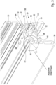
Figur 2 wurden ausschließlich die Horizontalprofile 23 und 24 mit eingesetzten Halteleisten 1 dargestellt. Dabei werden in den beiden Profilen 23 und 24 jeweils die Halteleiste 1 über eine Abwinkelung 12 eingesetzt. Aus dieser Darstellung geht bei dem Horizontalprofil 24 deutlich hervor, dass oberhalb der Bohrung 31 eine kleinere Bohrung 38 in dem verstärkt ausgebildeten Verbindungsabschnitt 61 vorhanden ist. Somit kann das Verbindungslager 32 mit einer durchgehenden Führung 59, gemäß dem in denFiguren 9 und 10 dargestellten Verbindungselement 48, eingesetzt werden. Durch die seitliche Führung 59 wird das Einsetzen des Verbindungselementes 48 nicht nur wesentlich erleichtert, sondern es wird auch gleichzeitig gewährleistet, dass es nicht zu einer Verwerfung der Profile 23 und 24 kommt. - Zur Anlage der Scheiben 45 oder dergleichen zur Gebäudeaußenseite 26 sind in den auskragenden Schenkelausführungen der Horizontalprofile 23 und 24 und zum Abschluss an die Vertikalprofile jeweils Dichtungsaufnahmen 35 vorhanden.
- Das Horizontalprofil 24 nach
Figur 3 , in einer Querschnittsdarstellung, gibt das Verbindungslager 32 mit der verstärkten Materialausführung in dem Verbindungsabschnitt 61 mit der Rahmenauflage 15 wieder. Durch die Konstruktion wird es möglich, dass durch die Stoßverbindung zwischen dem Vertikalprofil 27 und dem Horizontalprofil 23 und 24 eine dauerhafte, sichere, kraft- und formschlüssige Verbindung bereitgestellt wird, ohne dass zusätzlich weitere Bauelemente eingesetzt werden müssen. Die Querschnittsverstärkung stellt in dem Verbindungsabschnitt 61 mit der Führung 59 eine einfache Verbindung dar und es müssen keine weiteren Bauelemente für die Stabilisierung bei der Ausführung einer Rahmeneckverbindung bereitgestellt werden, die auch zu einer Gewichtserhöhung führen würden. - Durch die Ausschnittdarstellung des Details der
Figur 3 wird in derFigur 4 verdeutlicht, wie die Halteleiste 1 innerhalb des offenen Aufnahmeraumes 16 mit dem vorstehenden Haken 12 eingesetzt und gegen das plattenförmige Element 45 angestellt werden kann. Dabei gibt dieFigur 4 eine erste bevorzugte Ausführung einer Halteleiste 1 wieder. Die Halteleiste 1 weist einen allseits geschlossenen Hohlraum 6 auf, der außenseits des Torblattes durch eine Außenwand 4 und innenseits durch eine Anlegeseite 3, sowie einem oberseitigen Zwischenschenkel 5 und einer unterseitigen Basis 7 umschlossen wird. Die Anlageseite 3 führt im eingebauten Zustand zu einem Kontakt mit der Scheibe 45. Die Anlageseite 3 muss dabei den notwendigen Druck gegen die Scheibe 45 oder ein anderes plattenförmiges Element aufbringen, sodass zwischen der Anlageseite 3 und der Scheibe 45 kein Wasser von außen eindringen kann. Dieses kann insbesondere dadurch erzielt werden, dass die Halteleiste 1 aus einem schlagzähen Kunststoff mit einer hohen Shorehärte hergestellt wird, die trotzdem für einen hohen Anlagedruck und damit großen Adhäsionskräften an der Scheibe 45 sorgt. Es ist aber auch möglich die Halteleiste 1 aus einem anderen Material, wie z.B. Aluminium, herzustellen. - Die Basis 7 der Halteleiste 1 besteht aus einer im Wesentlichen geraden Auflageseite 9, dem sich daran anschließenden Haken 12 und einer daran anschließenden Seite mit einer Anschrägung 8, die in einem äußeren Auflagepunkt 11 endet. Die Auflageseite 9 und der Auflagepunkt 11 liegen auf dem gleichen Höhenniveau. Die Anschrägung 8, ausgehend von dem Auflagepunkt 11, liegt im Wesentlichen in einem Bereich von 1° bis 10°. Der Haken 12 ist aufgeteilt in einen ersten Abschnitt 10 und einen zweiten Abschnitt 60. Der erste Abschnitt 10 ist gegenüber der im Wesentlichen geraden Auflageseite 9 um einen Winkel zwischen 91 ° und 110° angestellt. Im Anschluss an diesen ersten Abschnitt 10 ist der zweite Abschnitt 12 jedoch wieder in Richtung zur Auflageseite 6 angeschrägt, wobei dieser Winkel, ausgehend von dem ersten Abschnitt 10, etwa zwischen 40° und 50° ausgebildet ist. Endseits des zweiten Abschnittes 12 ist ein vorspringender Anlagepunkt 13 vorhanden. In den Aufnahmeabschnitt 16 tauchen der Abschnitt 10 und die Abwinkelung 60 des Hakens 12 ein. Dabei liegt die Auflageseite 9 auf dem Rahmenauflager 15 der Profile 23, 24, 27 der Rahmenausbildung auf. Gleichzeitig hat der Auflagepunkt 11 einen weiteren Kontakt mit dem Rahmenauflager 15. Während der Auflagepunkt 11 in Kontakt mit dem Schenkel 20 steht, steht der Abschnitt 10 des Hakens 12 seitlich mit einem Gegenlager 19 der Rahmenausbildung in dem Aufnahmeabschnitt 16 in Kontakt. Durch die Schrägstellung der Abwinkelung 60 des Hakens 12 kommt diese innerhalb des Aufnahmeabschnittes 16 endseits in Kontakt mit einer Innenwand 17 an einer Anlagewand 18 über den Anlagepunkt 13. Durch diese Art der Konstruktion wird gewährleistet, dass der Montageleiste 1 mit den Kontaktbereichen ein sicherer und dauerhafter Halt zugesprochen werden kann. Die Rahmenausbildung weist außenseits eine Rahmenprofilaußenseite 14 auf, die nach Einsatz der Montageleiste 1 im Wesentlichen fluchtend mit der Außenwand 4 der Halteleiste 1 ausgerichtet ist.
- In der
Figur 5 wird eine weitere bevorzugte Ausführungsform der Montageleiste 1 wiedergegeben. Bei dieser Ausführungsform sind an der Anlageseite 3 zusätzlich Dichtlippen 21 ausgebildet. Diese Dichtlippen 21 weisen eine geringere Shorehärte auf, als die Halteleiste selbst. Dieses bedeutet, dass die beiden Komponenten der Halteleiste 1 durch ein 2K-Spritzverfahren in einem Arbeitsgang hergestellt werden können, sodass die Anlageseite 3 aus einem Thermoplast und die Dichtlippen aus einem Elastomer bestehen können. - In einer weiteren Ausschnittdarstellung nach
Figur 9 wird noch einmal auf die Gestaltung der Stoßverbindung zwischen dem Vertikalprofil 27 und einem der Horizontalprofile 23 oder 24 eingegangen. Durch diese Darstellung wird deutlich, dass es in dem Bereich, in dem das Verbindungselement 48 in den Verbindungsabschnitt 61 eintaucht, eine im Wesentlichen stark vergrößerte Profilausbildung gegenüber den anderen Wandungen der Aluminiumprofilelemente gibt. Durch diese Profilelementverdickung wird das Verbindungslager 32 in die Lage versetzt, dass es durch das Anziehen des Verbindungselementes 48 nicht zu einer Verspannung eines der verwendeten Aluminiumprofilelemente kommt. - Eine beispielhafte bevorzugte Ausbildung eines Vertikalprofils 27 gibt die
Figur 7 wieder. In dieser Ausführungsform wird ein Außenschenkel 40 dargestellt, der an einem Ende einen auskragenden Bereich für eine Dichtungsaufnahme 35 aufweist. Auch hier sind wieder ein innerer und ein äu-ßerer Hohlraum vorhanden. Der äußere Hohlraum wird durch einen Zwischensteg 41 von dem inneren Hohlraum getrennt. Die Schraubkanäle haben nur die funktionelle Aufgabe mit der Stoßverbindung einzugehen. Distanziert wird der Außenschenkel 40 von dem Zwischensteg 41 auch hier wieder durch Isolierstege 22. Es wird noch einmal auf die kraft- und formschlüssige Verbindung der Einspannabschnitte 53 der Isolierstege 22 mit den Aluminiumprofilelementen hingewiesen. Die Isolierstege 22 weisen hier eine im Wesentlichen gerade Distanz 52 auf, an die sich endseits jeweils Versätze 54 anschließen. Die Versätze 54 gehen anschließend jeweils in die Einspannabschnitte 53 über. Zur Innenseite des Gebäudes ist auch bei der Profilausbildung nachFigur 7 ein innerer Hohlraum vorhanden, der einseitig mit dem Aufnahmeabschnitt 16 für die Halteleiste 1 ausgebildet ist. - In der
Figur 8 wird eine weitere, modifizierte, bevorzugte Ausführungsform eines Vertikalprofils 37 wiedergegeben. Das Vertikalprofil 37 wird im Wesentlichen durch einen Außenschenkel 46 und mit diesem verbundene Isolierstege 22, die endseits dann mit einem Zwischensteg 56 verbunden sind, gebildet. Ein solches Vertikalprofil 37 wird dann verwendet, wenn die Rahmenausbildung aus mehreren, d.h., in sich geschlossenen Feldern für Scheiben 45, besteht. Dies zeigt sich auch daran, dass der innere Hohlraum außenseits durch einen Innenschenkel 47 abgeschlossen wird. Der Innenschenkel 47 weist an seinen beiden vertikalen Abschnitten jeweils die Aufnahmeabschnitte 16 für die Halteleisten 1 und damit für den Einsatz von Scheiben 45 auf. Der Außenschenkel 46 hat an beiden Seiten auskragende Enden mit jeweils einer Dichtungsaufnahme 35. - Die
Figur 6 zeigt einen oberen Abschluss eines Sektionaltorblattes. Dabei wird die Ausführung nachFigur 6 so verwendet, dass eine Dichtungsaufnahme 36 oberseits mit einem Dichtungsfuß 44 an einer auskragenden oberen Abschlussdichtung 43 ausführbar ist. Eine Zwischenwand 55 trennt auch hier den äußeren und den inneren Hohlraum voneinander. - Den unteren Abschnitt eines Sektionaltorblattes, das zum Beispiel mit einer Rahmenausbildung versehen wurde, zeigt die
Figur 10 , wobei hier ein Bodenabschlussprofil 49 verwendet wird. Dieses Bodenabschlussprofil 49 weist gegenüber den anderen horizontal verwendeten Profilen 23 und 24 eine wesentlich höhere Ausbildung auf. Dadurch ist der äußere Hohlraum durch mehrere Isolierstege 22 unterteilt, um so neben einer höheren Festigkeit für das Bodenabschlussprofil 49 gleichzeitig auch eine gute Wärmedämmung zu erzielen. Innerhalb einer Dichtungsaufnahme 50 ist die Bodendichtung 51 mit ihrem Dichtungsfuss 42 eingesetzt, die den unteren Abschluss zu einer gebäudeseitigen Aufstandsfläche bildet. -
- 1
- Halteleiste
- 2
- Profilversatz
- 3
- Anlageseite
- 4
- Außenwand
- 5
- Zwischenschenkel
- 6
- Hohlraum
- 7
- Basis
- 8
- Anschrägung
- 9
- Auflageseite
- 10
- Abschnitt
- 11
- Auflagepunkt
- 12
- Haken
- 13
- Anlagepunkt
- 14
- Rahmenprofilaußenseite
- 15
- Rahmenauflager
- 16
- Aufnahmeabschnitt
- 17
- Innenwand
- 18
- Anlagewand
- 19
- Gegenlager
- 20
- Schenkel
- 21
- Dichtlippen
- 22
- Isoliersteg
- 23
- Horizontalprofil
- 24
- Horizontalprofil
- 25
- Zwischensteg
- 26
- Gebäudeaußenseite
- 27
- Vertikalprofil
- 28
- Außenschenkel
- 29
- Innenschenkel
- 30
- Außenschenkel
- 31
- Bohrung
- 32
- Verbindungslager
- 33
- Dichtungselement
- 34
- Absatz
- 35
- Dichtungsaufnahme
- 36
- Dichtungsaufnahme
- 37
- Vertikalprofil
- 38
- Bohrung
- 39
- Verrundung
- 40
- Außenschenkel
- 41
- Zwischensteg
- 42
- Dichtungsfuss
- 43
- Abschlussdichtung
- 44
- Dichtungsfuß
- 45
- Scheiben
- 46
- Außenschenkel
- 47
- Innenschenkel
- 48
- Verbindungselement
- 49
- Bodenabschlussprofil
- 50
- Dichtungsaufnahme
- 51
- Bodendichtung
- 52
- Distanz
- 53
- Einspannabschnitt
- 54
- Versatz
- 55
- Zwischenwand
- 56
- Zwischensteg
- 57
- Innenschenkel
- 58
- Endschenkel
- 59
- Führung
- 60
- Abwinkelung
- 61
- Verbindungsabschnitt
Claims (11)
- Paneelelement mit einer Rahmenausbildung für ein Sektionaltorblatt, das aus mehreren Paneelelementen besteht, die untereinander scharnierend miteinander verbunden sind, wobei das Sektionaltorblatt in seitlichen Führungen ortsveränderbar geführt wird, wobei die Rahmenausbildung aus einem oberen horizontalen Aluminiumprofilelement (23) und einem unteren horizontalen Aluminiumprofilelement (24) und vertikalen Aluminiumprofilelementen (27, 37) besteht,
wobei die Aluminiumprofilelemente (23, 24, 27, 37) innenseitig Isolierstege (22) aufweisen, wobei die Isolierstege (22) mit den außen- und innenseitigen Aluminiumprofilelementen (23, 24, 27, 37) kraft- und formschlüssig verbunden sind, sodass im Querschnitt ein äu-ßerer, in sich geschlossener Hohlraum und ein innerer Hohlraum entstehen, die durch einen Zwischensteg (25, 56, 41) getrennt sind, wobei die Rahmenausbildung mit einem auswechselbaren, plattenförmigen Element als Scheibe (45) ausgefüllt ist, wobei die Scheibe (45) durch Halteleisten (1) gehalten wird, wobei zwischen Außenschenkeln (28, 30, 42, 46) der Aluminiumprofilelemente (23, 24, 27, 37) und dem innenseitigen Zwischensteg (25, 56) die Isolierstege (22) kraft- und formschlüssig befestigt sind und den äußeren Hohlraum abschließen, wobei der innere Hohlraum von dem Zwischensteg (25, 56, 41) zu einem Innenschenkel (29, 57, 40) des Aluminiumprofilelementes (23, 24, 27, 37) oberseits der Rahmenausbildung direkt oder indirekt mit dem Zwischensteg (25, 56, 41) verbunden ist, wobei unterseits der horizontalen Aluminiumprofilelemente (23, 34) ein Verbindungsabschnitt (61) besteht, der zwischen dem Innenschenkel (29, 57) und dem Zwischensteg (25, 56) ausgebildet ist, wobei über den inneren Hohlraum der horizontalen Aluminiumprofilelemente (23, 24) zu den vertikalen Aluminiumprofilelementen (27, 37) Schraubverbindungen bestehen, dadurch gekennzeichnet dass der Verbindungsabschnitt (61) eine Querschnittsverstärkung gegenüber den horizontalen Aluminiumprofilelementen (23, 24) und den vertikalen Aluminiumprofilelementen (27, 37) aufweist. - Paneelelement nach Anspruch 1, dadurch gekennzeichnet, dass der Verbindungsabschnitt (61) eine Vertiefung mit einer Führung (59) in Form eines Verbindungslagers (32) für eine Verbindung der horizontalen Aluminiumprofilelemente (23, 24) mit den vertikalen Aluminiumprofilelementen (27, 37) über Verbindungselemente (48) in einer Stoßverbindung aufweist.
- Paneelelement nach Anspruch 1, dadurch gekennzeichnet, dass der innere Hohlraum Bohrungen (31) zur Stoßverbindung der horizontalen Aluminiumprofilelemente (23, 24) mit den vertikalen Aluminiumprofilelemente (27, 37) aufweist.
- Paneelelement nach Anspruch 1, dadurch gekennzeichnet, dass in dem Verbindungsabschnitt (61) korrespondiere Bohrungen (38) mit den Bohrungen (31) enthalten sind.
- Paneelelement nach Anspruch 1, dadurch gekennzeichnet, dass die Unterseite des unteren horizontalen Aluminiumprofilelements (24) für eine korrespondierende Verwendung mit dem oberen horizontalen Aluminiumprofilelement (23) eine Dichtungsaufnahme (36) aufweist, in der ein Dichtungselement (33) angeordnet ist, wobei das untere horizontale Aluminiumprofilelement (24) einen inneren und äußeren Hohlraum aufweist, wobei die Hohlräume durch einen innen verlaufenden Zwischensteg (56) getrennt sind.
- Paneelelement nach Anspruch 1, dadurch gekennzeichnet, dass der äußere Hohlraum des unteren horizontalen Aluminiumprofilelements (24) ober- und unterseits durch Isolierstege (22) abgeschlossen ist, die einerseits mit dem Zwischensteg (56) und andererseits mit einem Außenschenkel (30) des unteren horizontalen Aluminiumprofilelements (24) kraft- und formschlüssig verbunden sind, und dass dabei ein Außenschenkel (30) im Anschluss an die Einspannung der Isolierstege (22) einen auskragenden Schenkel mit einer Dichtungsaufnahme (35) und im Anschluss an die untere Einspannung des weiteren Isoliersteges (22) einen auskragenden Endschenkel (58) aufweist.
- Paneelelement nach Anspruch 1, dadurch gekennzeichnet, dass die Halteleiste (1) aus einem schlagzähen Kunststoff mit einer hohen Shorehärte oder Leichtmetall besteht, mit einem allseits umschlossenen Hohlraum (6), der eine unterseitige Basis (7) aufweist, die im Anschluss an eine etwa geraden Auflageseite (9) einen abstehenden Haken (12) aufweist, und dass im Anschluss an den Haken (12) eine von einem endseitigen Auflagepunkt (11) zum Haken (12) gerichtete, ansteigende Anschrägung (8) ausgebildet ist.
- Paneelelement nach Anspruch 7, dadurch gekennzeichnet, dass der Auflagepunkt (11) und die Auflageseite (9) maßlich auf einer Ebene liegen, wobei die von dem Auflagepunkt (11) zum Haken (12) ansteigende Anschrägung (8) in einem Winkel von etwa 1° bis 10° ausgebildet ist.
- Paneelelement nach Anspruch 7, dadurch gekennzeichnet, dass der Haken (12) durch einen ersten Abschnitt (10) mit sich daran anschließendem zweiten Abschnitt (60) bestimmt wird, wobei der erste Abschnitt (10) des Hakens (12) gegenüber der etwa geraden Auflageseite (9) in einem Winkel zwischen 91° und 110° angestellt ist, und dass sich der an den ersten Abschnitt (10) des Hakens (12) anschließende zweite Abschnitt (60) mit einer Winkelstellung von über 90° in Richtung zu der Anlageseite (9) ausgebildet ist, wobei der zweite Abschnitt (12) endseits durch einen vorstehenden Anlagepunkt (13) abgeschlossen wird.
- Paneelelement nach einem oder mehreren der vorhergehenden Ansprüche, dadurch gekennzeichnet, dass die Isolierstege (22) eine große Querschnittsformstabilität und schlechte Wärmeleitfähigkeit aufweisen und aus einem Polyamid mit mindestens einem Zuschlagstoff bestehen, wobei die Enden der Isolierstege (22) mit Einspannabschnitten versehen sind, die mit den Aluminiumprofilelementen (23, 24, 27, 37) kraft- und formschlüssig verbunden sind.
- Paneelelement nach Anspruch 10, dadurch gekennzeichnet, dass der Zuschlagstoff aus langgestreckten Glasfasern besteht.
Applications Claiming Priority (2)
| Application Number | Priority Date | Filing Date | Title |
|---|---|---|---|
| DE102022113450 | 2022-05-27 | ||
| EP23175694.1A EP4299871B1 (de) | 2022-05-27 | 2023-05-26 | Rahmenausbildung als teil eines paneelelementes für ein sektionaltorblatt |
Related Parent Applications (2)
| Application Number | Title | Priority Date | Filing Date |
|---|---|---|---|
| EP23175694.1A Division-Into EP4299871B1 (de) | 2022-05-27 | 2023-05-26 | Rahmenausbildung als teil eines paneelelementes für ein sektionaltorblatt |
| EP23175694.1A Division EP4299871B1 (de) | 2022-05-27 | 2023-05-26 | Rahmenausbildung als teil eines paneelelementes für ein sektionaltorblatt |
Publications (2)
| Publication Number | Publication Date |
|---|---|
| EP4471248A2 true EP4471248A2 (de) | 2024-12-04 |
| EP4471248A3 EP4471248A3 (de) | 2025-03-12 |
Family
ID=86604929
Family Applications (2)
| Application Number | Title | Priority Date | Filing Date |
|---|---|---|---|
| EP24204059.0A Pending EP4471248A3 (de) | 2022-05-27 | 2023-05-26 | Rahmenausbildung als teil eines paneelelementes für ein sektionaltorblatt |
| EP23175694.1A Active EP4299871B1 (de) | 2022-05-27 | 2023-05-26 | Rahmenausbildung als teil eines paneelelementes für ein sektionaltorblatt |
Family Applications After (1)
| Application Number | Title | Priority Date | Filing Date |
|---|---|---|---|
| EP23175694.1A Active EP4299871B1 (de) | 2022-05-27 | 2023-05-26 | Rahmenausbildung als teil eines paneelelementes für ein sektionaltorblatt |
Country Status (5)
| Country | Link |
|---|---|
| EP (2) | EP4471248A3 (de) |
| DE (2) | DE102023113971A1 (de) |
| DK (1) | DK4299871T3 (de) |
| ES (1) | ES3016643T3 (de) |
| PL (1) | PL4299871T3 (de) |
Citations (4)
| Publication number | Priority date | Publication date | Assignee | Title |
|---|---|---|---|---|
| DE102012010028A1 (de) | 2012-05-21 | 2013-11-21 | Hörmann KG Brockhagen | Rahmenanordnung für ein sektionaltorpaneel |
| DE202018103416U1 (de) | 2018-05-22 | 2019-08-23 | Krispol Sp.z.o.o. | Sektionaltor mit anhubbarem Torblatt |
| DE202019105111U1 (de) | 2019-05-21 | 2020-08-24 | Krispol Sp.z.o.o. | Sektionaltor mit Hubflügel |
| WO2021209536A1 (en) | 2020-04-16 | 2021-10-21 | Assa Abloy Entrance Systems Ab | Entrance system |
Family Cites Families (6)
| Publication number | Priority date | Publication date | Assignee | Title |
|---|---|---|---|---|
| GB2220024A (en) | 1988-06-22 | 1989-12-28 | Rehau Ag & Co | Glazing |
| GB2275957B (en) * | 1993-03-13 | 1996-10-23 | Deceuninck Ltd | Improvements in or relating to window assemblies |
| DE29900650U1 (de) * | 1999-01-19 | 1999-04-22 | TKI Technisch Konstruktive Interessengemeinschafts-GmbH Entwicklung- und Verwaltung von Aluminiumprofilsystemen, 63329 Egelsbach | Dichtungsanordnung für Fenster und Türen |
| DE10246932A1 (de) * | 2002-10-08 | 2004-04-22 | Aluplast Gmbh | Dichtung für ein Fensterprofil und Verfahren zu deren Herstellung |
| FR2897382B1 (fr) * | 2006-02-13 | 2008-04-25 | Stremler Soc Par Actions Simpl | "dispositif de verrouillage a au moins un point de condamnation" |
| DE102011105310A1 (de) | 2011-06-19 | 2012-12-20 | Marian Ionescu | Geschlossenes Profilsystem mit Dämmstoffkern |
-
2023
- 2023-05-26 DK DK23175694.1T patent/DK4299871T3/da active
- 2023-05-26 DE DE102023113971.1A patent/DE102023113971A1/de not_active Ceased
- 2023-05-26 EP EP24204059.0A patent/EP4471248A3/de active Pending
- 2023-05-26 ES ES23175694T patent/ES3016643T3/es active Active
- 2023-05-26 PL PL23175694.1T patent/PL4299871T3/pl unknown
- 2023-05-26 DE DE202023002954.6U patent/DE202023002954U1/de active Active
- 2023-05-26 EP EP23175694.1A patent/EP4299871B1/de active Active
Patent Citations (5)
| Publication number | Priority date | Publication date | Assignee | Title |
|---|---|---|---|---|
| DE102012010028A1 (de) | 2012-05-21 | 2013-11-21 | Hörmann KG Brockhagen | Rahmenanordnung für ein sektionaltorpaneel |
| EP2666948A1 (de) | 2012-05-21 | 2013-11-27 | Hörmann KG Brockhagen | Rahmenanordnung für ein Sektionaltorpaneel |
| DE202018103416U1 (de) | 2018-05-22 | 2019-08-23 | Krispol Sp.z.o.o. | Sektionaltor mit anhubbarem Torblatt |
| DE202019105111U1 (de) | 2019-05-21 | 2020-08-24 | Krispol Sp.z.o.o. | Sektionaltor mit Hubflügel |
| WO2021209536A1 (en) | 2020-04-16 | 2021-10-21 | Assa Abloy Entrance Systems Ab | Entrance system |
Also Published As
| Publication number | Publication date |
|---|---|
| DE102023113971A1 (de) | 2023-11-30 |
| EP4299871B1 (de) | 2024-12-25 |
| DK4299871T3 (da) | 2025-03-17 |
| EP4471248A3 (de) | 2025-03-12 |
| ES3016643T3 (en) | 2025-05-09 |
| PL4299871T3 (pl) | 2025-04-28 |
| DE202023002954U1 (de) | 2025-03-08 |
| EP4299871A1 (de) | 2024-01-03 |
Similar Documents
| Publication | Publication Date | Title |
|---|---|---|
| EP0616107B1 (de) | Stossverbindung von Hohlprofilabschnitten | |
| EP2666948B1 (de) | Rahmenanordnung für ein Sektionaltorpaneel | |
| DE2748623A1 (de) | Beschlag fuer einen glasfluegel, insbesondere fuer eine ganzglastuer | |
| EP0785335A1 (de) | Glasrandhalterung | |
| EP4283086B1 (de) | Rahmenausbildung als paneelelement für ein sektionaltorblatt | |
| DE1958087A1 (de) | Fenster oder Tuer | |
| EP4299871B1 (de) | Rahmenausbildung als teil eines paneelelementes für ein sektionaltorblatt | |
| DE69606211T2 (de) | Verbundprofile und ihr Zusammenbau für hochisolierte und holzverkleidete Tür- und Fensterrahmen | |
| EP1744003A2 (de) | Flügel mit Falzgrunddichtung | |
| DE202004000817U1 (de) | Rahmenkörper aus einem hohlen, stranggepreßten Kunststoffprofil für Fenster und Türen | |
| DE4235687A1 (de) | Mehrteiliges Profil für wärmeisolierende Gebäudeverkleidungen, Verglasungen oder Fensterrahmen | |
| DE60130085T2 (de) | Kunststoffflügel, sowie sein Herstellungsverfahren und zweiflügelige Öffnung, z.B. für ein Fenster | |
| EP2487313A1 (de) | Rahmenkonstruktion für ein Fenster oder eine Tür | |
| DE20100618U1 (de) | Rahmenprofil | |
| DE19609624C2 (de) | Gebäudefenster und/oder Gebäudefenstertür | |
| WO2010006626A1 (de) | Putzleiste | |
| EP2060726B1 (de) | Hohlkammerprofil | |
| EP4345240B1 (de) | Leichtmetallprofilverbindung | |
| DE202019104572U1 (de) | Profilverbinder zur Verbindung von Zargenprofilen und Anordnung damit | |
| DE102019108109A1 (de) | Universeller Schwellenverbinder mit Wechselelement | |
| DE3301324A1 (de) | Verbesserungen bei rahmenteilen fuer fenster, tueren und anderen rahmenkonstruktionen | |
| DE102008047642A1 (de) | Tür | |
| EP2072744A2 (de) | Zargenprofil für eine Hebe-Schiebetür | |
| DE19854203A1 (de) | Pfosten/Riegel-Fassade für ein Gebäude | |
| DE102022106097A1 (de) | Türrahmen mit Bodenschwelle |
Legal Events
| Date | Code | Title | Description |
|---|---|---|---|
| PUAI | Public reference made under article 153(3) epc to a published international application that has entered the european phase |
Free format text: ORIGINAL CODE: 0009012 |
|
| STAA | Information on the status of an ep patent application or granted ep patent |
Free format text: STATUS: REQUEST FOR EXAMINATION WAS MADE |
|
| 17P | Request for examination filed |
Effective date: 20241021 |
|
| AC | Divisional application: reference to earlier application |
Ref document number: 4299871 Country of ref document: EP Kind code of ref document: P |
|
| AK | Designated contracting states |
Kind code of ref document: A2 Designated state(s): AL AT BE BG CH CY CZ DE DK EE ES FI FR GB GR HR HU IE IS IT LI LT LU LV MC ME MK MT NL NO PL PT RO RS SE SI SK SM TR |
|
| REG | Reference to a national code |
Ref country code: DE Ref legal event code: R079 Free format text: PREVIOUS MAIN CLASS: E06B0003580000 Ipc: E06B0003480000 |
|
| PUAL | Search report despatched |
Free format text: ORIGINAL CODE: 0009013 |
|
| AK | Designated contracting states |
Kind code of ref document: A3 Designated state(s): AL AT BE BG CH CY CZ DE DK EE ES FI FR GB GR HR HU IE IS IT LI LT LU LV MC ME MK MT NL NO PL PT RO RS SE SI SK SM TR |
|
| RIC1 | Information provided on ipc code assigned before grant |
Ipc: E06B 3/58 20060101ALI20250203BHEP Ipc: E06B 3/263 20060101ALI20250203BHEP Ipc: E06B 3/48 20060101AFI20250203BHEP |