EP4297918B1 - Giess-walz-verbundanlage und verfahren zur herstellung von warmband mit einer enddicke <1,2 mm auf der giess-walz-verbundanlage - Google Patents
Giess-walz-verbundanlage und verfahren zur herstellung von warmband mit einer enddicke <1,2 mm auf der giess-walz-verbundanlage Download PDFInfo
- Publication number
- EP4297918B1 EP4297918B1 EP22708862.2A EP22708862A EP4297918B1 EP 4297918 B1 EP4297918 B1 EP 4297918B1 EP 22708862 A EP22708862 A EP 22708862A EP 4297918 B1 EP4297918 B1 EP 4297918B1
- Authority
- EP
- European Patent Office
- Prior art keywords
- rolling
- slabs
- rough
- continuous casting
- rolled strip
- Prior art date
- Legal status (The legal status is an assumption and is not a legal conclusion. Google has not performed a legal analysis and makes no representation as to the accuracy of the status listed.)
- Active
Links
Images

Classifications
-
- B—PERFORMING OPERATIONS; TRANSPORTING
- B22—CASTING; POWDER METALLURGY
- B22D—CASTING OF METALS; CASTING OF OTHER SUBSTANCES BY THE SAME PROCESSES OR DEVICES
- B22D11/00—Continuous casting of metals, i.e. casting in indefinite lengths
- B22D11/12—Accessories for subsequent treating or working cast stock in situ
-
- B—PERFORMING OPERATIONS; TRANSPORTING
- B21—MECHANICAL METAL-WORKING WITHOUT ESSENTIALLY REMOVING MATERIAL; PUNCHING METAL
- B21B—ROLLING OF METAL
- B21B1/00—Metal-rolling methods or mills for making semi-finished products of solid or profiled cross-section; Sequence of operations in milling trains; Layout of rolling-mill plant, e.g. grouping of stands; Succession of passes or of sectional pass alternations
- B21B1/46—Metal-rolling methods or mills for making semi-finished products of solid or profiled cross-section; Sequence of operations in milling trains; Layout of rolling-mill plant, e.g. grouping of stands; Succession of passes or of sectional pass alternations for rolling metal immediately subsequent to continuous casting
- B21B1/466—Metal-rolling methods or mills for making semi-finished products of solid or profiled cross-section; Sequence of operations in milling trains; Layout of rolling-mill plant, e.g. grouping of stands; Succession of passes or of sectional pass alternations for rolling metal immediately subsequent to continuous casting in a non-continuous process, i.e. the cast being cut before rolling
-
- B—PERFORMING OPERATIONS; TRANSPORTING
- B21—MECHANICAL METAL-WORKING WITHOUT ESSENTIALLY REMOVING MATERIAL; PUNCHING METAL
- B21B—ROLLING OF METAL
- B21B1/00—Metal-rolling methods or mills for making semi-finished products of solid or profiled cross-section; Sequence of operations in milling trains; Layout of rolling-mill plant, e.g. grouping of stands; Succession of passes or of sectional pass alternations
- B21B1/02—Metal-rolling methods or mills for making semi-finished products of solid or profiled cross-section; Sequence of operations in milling trains; Layout of rolling-mill plant, e.g. grouping of stands; Succession of passes or of sectional pass alternations for rolling heavy work, e.g. ingots, slabs, blooms, or billets, in which the cross-sectional form is unimportant ; Rolling combined with forging or pressing
- B21B1/04—Metal-rolling methods or mills for making semi-finished products of solid or profiled cross-section; Sequence of operations in milling trains; Layout of rolling-mill plant, e.g. grouping of stands; Succession of passes or of sectional pass alternations for rolling heavy work, e.g. ingots, slabs, blooms, or billets, in which the cross-sectional form is unimportant ; Rolling combined with forging or pressing in a continuous process
-
- B—PERFORMING OPERATIONS; TRANSPORTING
- B21—MECHANICAL METAL-WORKING WITHOUT ESSENTIALLY REMOVING MATERIAL; PUNCHING METAL
- B21B—ROLLING OF METAL
- B21B13/00—Metal-rolling stands, i.e. an assembly composed of a stand frame, rolls, and accessories
- B21B13/22—Metal-rolling stands, i.e. an assembly composed of a stand frame, rolls, and accessories for rolling metal immediately subsequent to continuous casting, i.e. in-line rolling of steel
-
- C—CHEMISTRY; METALLURGY
- C21—METALLURGY OF IRON
- C21D—MODIFYING THE PHYSICAL STRUCTURE OF FERROUS METALS; GENERAL DEVICES FOR HEAT TREATMENT OF FERROUS OR NON-FERROUS METALS OR ALLOYS; MAKING METAL MALLEABLE, e.g. BY DECARBURISATION OR TEMPERING
- C21D6/00—Heat treatment of ferrous alloys
-
- C—CHEMISTRY; METALLURGY
- C21—METALLURGY OF IRON
- C21D—MODIFYING THE PHYSICAL STRUCTURE OF FERROUS METALS; GENERAL DEVICES FOR HEAT TREATMENT OF FERROUS OR NON-FERROUS METALS OR ALLOYS; MAKING METAL MALLEABLE, e.g. BY DECARBURISATION OR TEMPERING
- C21D8/00—Modifying the physical properties of ferrous metals or ferrous alloys by deformation combined with, or followed by, heat treatment
- C21D8/02—Modifying the physical properties of ferrous metals or ferrous alloys by deformation combined with, or followed by, heat treatment during manufacturing of plates or strips
-
- C—CHEMISTRY; METALLURGY
- C21—METALLURGY OF IRON
- C21D—MODIFYING THE PHYSICAL STRUCTURE OF FERROUS METALS; GENERAL DEVICES FOR HEAT TREATMENT OF FERROUS OR NON-FERROUS METALS OR ALLOYS; MAKING METAL MALLEABLE, e.g. BY DECARBURISATION OR TEMPERING
- C21D8/00—Modifying the physical properties of ferrous metals or ferrous alloys by deformation combined with, or followed by, heat treatment
- C21D8/02—Modifying the physical properties of ferrous metals or ferrous alloys by deformation combined with, or followed by, heat treatment during manufacturing of plates or strips
- C21D8/021—Modifying the physical properties of ferrous metals or ferrous alloys by deformation combined with, or followed by, heat treatment during manufacturing of plates or strips involving particular fabrication steps or treatments of ingots or slabs
-
- C—CHEMISTRY; METALLURGY
- C21—METALLURGY OF IRON
- C21D—MODIFYING THE PHYSICAL STRUCTURE OF FERROUS METALS; GENERAL DEVICES FOR HEAT TREATMENT OF FERROUS OR NON-FERROUS METALS OR ALLOYS; MAKING METAL MALLEABLE, e.g. BY DECARBURISATION OR TEMPERING
- C21D8/00—Modifying the physical properties of ferrous metals or ferrous alloys by deformation combined with, or followed by, heat treatment
- C21D8/02—Modifying the physical properties of ferrous metals or ferrous alloys by deformation combined with, or followed by, heat treatment during manufacturing of plates or strips
- C21D8/0221—Modifying the physical properties of ferrous metals or ferrous alloys by deformation combined with, or followed by, heat treatment during manufacturing of plates or strips characterised by the working steps
- C21D8/0226—Hot rolling
-
- C—CHEMISTRY; METALLURGY
- C21—METALLURGY OF IRON
- C21D—MODIFYING THE PHYSICAL STRUCTURE OF FERROUS METALS; GENERAL DEVICES FOR HEAT TREATMENT OF FERROUS OR NON-FERROUS METALS OR ALLOYS; MAKING METAL MALLEABLE, e.g. BY DECARBURISATION OR TEMPERING
- C21D8/00—Modifying the physical properties of ferrous metals or ferrous alloys by deformation combined with, or followed by, heat treatment
- C21D8/02—Modifying the physical properties of ferrous metals or ferrous alloys by deformation combined with, or followed by, heat treatment during manufacturing of plates or strips
- C21D8/0247—Modifying the physical properties of ferrous metals or ferrous alloys by deformation combined with, or followed by, heat treatment during manufacturing of plates or strips characterised by the heat treatment
- C21D8/0263—Modifying the physical properties of ferrous metals or ferrous alloys by deformation combined with, or followed by, heat treatment during manufacturing of plates or strips characterised by the heat treatment following hot rolling
-
- C—CHEMISTRY; METALLURGY
- C21—METALLURGY OF IRON
- C21D—MODIFYING THE PHYSICAL STRUCTURE OF FERROUS METALS; GENERAL DEVICES FOR HEAT TREATMENT OF FERROUS OR NON-FERROUS METALS OR ALLOYS; MAKING METAL MALLEABLE, e.g. BY DECARBURISATION OR TEMPERING
- C21D9/00—Heat treatment, e.g. annealing, hardening, quenching or tempering, adapted for particular articles; Furnaces therefor
- C21D9/52—Heat treatment, e.g. annealing, hardening, quenching or tempering, adapted for particular articles; Furnaces therefor for wires; for strips ; for rods of unlimited length
-
- B—PERFORMING OPERATIONS; TRANSPORTING
- B21—MECHANICAL METAL-WORKING WITHOUT ESSENTIALLY REMOVING MATERIAL; PUNCHING METAL
- B21B—ROLLING OF METAL
- B21B1/00—Metal-rolling methods or mills for making semi-finished products of solid or profiled cross-section; Sequence of operations in milling trains; Layout of rolling-mill plant, e.g. grouping of stands; Succession of passes or of sectional pass alternations
- B21B1/22—Metal-rolling methods or mills for making semi-finished products of solid or profiled cross-section; Sequence of operations in milling trains; Layout of rolling-mill plant, e.g. grouping of stands; Succession of passes or of sectional pass alternations for rolling plates, strips, bands or sheets of indefinite length
- B21B1/24—Metal-rolling methods or mills for making semi-finished products of solid or profiled cross-section; Sequence of operations in milling trains; Layout of rolling-mill plant, e.g. grouping of stands; Succession of passes or of sectional pass alternations for rolling plates, strips, bands or sheets of indefinite length in a continuous or semi-continuous process
- B21B1/26—Metal-rolling methods or mills for making semi-finished products of solid or profiled cross-section; Sequence of operations in milling trains; Layout of rolling-mill plant, e.g. grouping of stands; Succession of passes or of sectional pass alternations for rolling plates, strips, bands or sheets of indefinite length in a continuous or semi-continuous process by hot-rolling, e.g. Steckel hot mill
-
- B—PERFORMING OPERATIONS; TRANSPORTING
- B21—MECHANICAL METAL-WORKING WITHOUT ESSENTIALLY REMOVING MATERIAL; PUNCHING METAL
- B21B—ROLLING OF METAL
- B21B1/00—Metal-rolling methods or mills for making semi-finished products of solid or profiled cross-section; Sequence of operations in milling trains; Layout of rolling-mill plant, e.g. grouping of stands; Succession of passes or of sectional pass alternations
- B21B1/22—Metal-rolling methods or mills for making semi-finished products of solid or profiled cross-section; Sequence of operations in milling trains; Layout of rolling-mill plant, e.g. grouping of stands; Succession of passes or of sectional pass alternations for rolling plates, strips, bands or sheets of indefinite length
- B21B1/30—Metal-rolling methods or mills for making semi-finished products of solid or profiled cross-section; Sequence of operations in milling trains; Layout of rolling-mill plant, e.g. grouping of stands; Succession of passes or of sectional pass alternations for rolling plates, strips, bands or sheets of indefinite length in a non-continuous process
- B21B1/32—Metal-rolling methods or mills for making semi-finished products of solid or profiled cross-section; Sequence of operations in milling trains; Layout of rolling-mill plant, e.g. grouping of stands; Succession of passes or of sectional pass alternations for rolling plates, strips, bands or sheets of indefinite length in a non-continuous process in reversing single stand mills, e.g. with intermediate storage reels for accumulating work
- B21B1/34—Metal-rolling methods or mills for making semi-finished products of solid or profiled cross-section; Sequence of operations in milling trains; Layout of rolling-mill plant, e.g. grouping of stands; Succession of passes or of sectional pass alternations for rolling plates, strips, bands or sheets of indefinite length in a non-continuous process in reversing single stand mills, e.g. with intermediate storage reels for accumulating work by hot-rolling
-
- B—PERFORMING OPERATIONS; TRANSPORTING
- B21—MECHANICAL METAL-WORKING WITHOUT ESSENTIALLY REMOVING MATERIAL; PUNCHING METAL
- B21B—ROLLING OF METAL
- B21B15/00—Arrangements for performing additional metal-working operations specially combined with or arranged in, or specially adapted for use in connection with, metal-rolling mills
- B21B2015/0057—Coiling the rolled product
-
- B—PERFORMING OPERATIONS; TRANSPORTING
- B21—MECHANICAL METAL-WORKING WITHOUT ESSENTIALLY REMOVING MATERIAL; PUNCHING METAL
- B21B—ROLLING OF METAL
- B21B15/00—Arrangements for performing additional metal-working operations specially combined with or arranged in, or specially adapted for use in connection with, metal-rolling mills
- B21B2015/0064—Uncoiling the rolled product
-
- B—PERFORMING OPERATIONS; TRANSPORTING
- B21—MECHANICAL METAL-WORKING WITHOUT ESSENTIALLY REMOVING MATERIAL; PUNCHING METAL
- B21B—ROLLING OF METAL
- B21B15/00—Arrangements for performing additional metal-working operations specially combined with or arranged in, or specially adapted for use in connection with, metal-rolling mills
- B21B2015/0092—Welding in the rolling direction
-
- B—PERFORMING OPERATIONS; TRANSPORTING
- B21—MECHANICAL METAL-WORKING WITHOUT ESSENTIALLY REMOVING MATERIAL; PUNCHING METAL
- B21B—ROLLING OF METAL
- B21B2201/00—Special rolling modes
- B21B2201/10—Endless rolling
-
- B—PERFORMING OPERATIONS; TRANSPORTING
- B21—MECHANICAL METAL-WORKING WITHOUT ESSENTIALLY REMOVING MATERIAL; PUNCHING METAL
- B21B—ROLLING OF METAL
- B21B2261/00—Product parameters
- B21B2261/02—Transverse dimensions
- B21B2261/04—Thickness, gauge
-
- B—PERFORMING OPERATIONS; TRANSPORTING
- B21—MECHANICAL METAL-WORKING WITHOUT ESSENTIALLY REMOVING MATERIAL; PUNCHING METAL
- B21B—ROLLING OF METAL
- B21B2261/00—Product parameters
- B21B2261/02—Transverse dimensions
- B21B2261/06—Width
-
- B—PERFORMING OPERATIONS; TRANSPORTING
- B21—MECHANICAL METAL-WORKING WITHOUT ESSENTIALLY REMOVING MATERIAL; PUNCHING METAL
- B21B—ROLLING OF METAL
- B21B2261/00—Product parameters
- B21B2261/20—Temperature
-
- B—PERFORMING OPERATIONS; TRANSPORTING
- B21—MECHANICAL METAL-WORKING WITHOUT ESSENTIALLY REMOVING MATERIAL; PUNCHING METAL
- B21B—ROLLING OF METAL
- B21B45/00—Devices for surface or other treatment of work, specially combined with or arranged in, or specially adapted for use in connection with, metal-rolling mills
- B21B45/04—Devices for surface or other treatment of work, specially combined with or arranged in, or specially adapted for use in connection with, metal-rolling mills for de-scaling, e.g. by brushing
- B21B45/06—Devices for surface or other treatment of work, specially combined with or arranged in, or specially adapted for use in connection with, metal-rolling mills for de-scaling, e.g. by brushing of strip material
-
- B—PERFORMING OPERATIONS; TRANSPORTING
- B21—MECHANICAL METAL-WORKING WITHOUT ESSENTIALLY REMOVING MATERIAL; PUNCHING METAL
- B21B—ROLLING OF METAL
- B21B45/00—Devices for surface or other treatment of work, specially combined with or arranged in, or specially adapted for use in connection with, metal-rolling mills
- B21B45/04—Devices for surface or other treatment of work, specially combined with or arranged in, or specially adapted for use in connection with, metal-rolling mills for de-scaling, e.g. by brushing
- B21B45/08—Devices for surface or other treatment of work, specially combined with or arranged in, or specially adapted for use in connection with, metal-rolling mills for de-scaling, e.g. by brushing hydraulically
Definitions
- the present invention relates to the technical field of iron and steel metallurgy.
- the invention relates to a combined casting and rolling plant for the production of hot strip with a final thickness of ⁇ 1.2 mm.
- the invention relates to a method for producing hot strip with a final thickness ⁇ 1.2 mm on a combined casting and rolling plant.
- Casting and rolling composite plants for the production of hot strip by combining continuous casting and hot rolling are well known, e.g. a CSP plant from SMS, an Arvedi ESP plant from Primetals Technologies or a QSP DUE plant from Danieli.
- HSM hot strip mills
- TSCR thin slab casting and rolling
- HSM uses slabs from conventional continuous casting plants, which must be heated from ambient temperature to the desired forming temperature before hot forming (high energy consumption). Hot rolling mills are able to process many steel grades in large quantities. One of their biggest disadvantages is that the final strip thickness must be over 1.2 mm in order not to violate the valid feed conditions. The production of ultra-thin strips therefore always requires a downstream cold rolling process.
- 2-strand TSCR processes such as CSP or QSP/DUE
- two continuous casting plants are connected to the hot rolling mill by tunnel furnaces; the casting heat is utilized and high capacities are theoretically possible (depending on the product portfolio).
- a major disadvantage is the drop in capacity when producing thin or ultra-thin strip.
- the continuous process decouples one cast strand from the rolling mill and the output drops by 50%.
- a combined casting and rolling plant for producing hot strip with a final thickness of ⁇ 1.0 mm comprising a first and a second continuous casting plant 2, 2' for casting liquid steel into slabs, a first roller hearth furnace 4 for heating the slabs from the first continuous casting plant 2 to rolling temperature and a separate second roller hearth furnace 4' for heating the slabs from the second continuous casting plant 2' to rolling temperature, and a ferry 5 for feeding slabs from the second continuous casting plant 2' into the first roller hearth furnace 4.
- the slabs are then pre-rolled in a reversing stand group 7 to form a preliminary strip and wound up in a Steckel furnace.
- the preliminary strips are then welded together by a welding machine to form an endless preliminary strip and finish-rolled in the finishing train 15. Since the slabs of the first and second continuous casting plants 2, 2' are heated differently in the roller hearth furnaces, the plant is not suitable for the production of high-quality hot strip.
- the object of the invention is to provide a novel combined casting-rolling plant for producing hot strip with a final thickness ⁇ 1.2 mm, preferably ⁇ 1.0 mm, and to provide a method for producing a hot strip with a final thickness ⁇ 1.2 mm, preferably ⁇ 1.0 mm, on a combined casting-rolling plant, in which high-quality ultra-thin hot strip with a high capacity, i.e. with a capacity between 3.5 and 5.5 M t/a, can be produced by continuous casting and hot rolling on the combined casting-rolling plant.
- the combined casting and rolling plant has at least two separate continuous casting plants, each with separate molds and curved strand guides.
- the continuous casting of two or three strands ( twin or triple casting ) using a split mold on a continuous casting plant is not according to the invention, since no separate continuous casting plants are available.
- Each continuous casting plant pours liquid steel into slabs.
- the slabs can be thin or medium slabs with a thickness of 140 to 240 mm and a width of between 1100 and 2300 mm.
- the slab length is typically between 11.5 and 26 m.
- the slabs produced on the continuous casting plants are fed in a heat-insulated manner to a slab manipulator, which takes the slabs from the continuous casting plants to a walking beam furnace. In the walking beam furnace, e.g.
- the slabs are evenly heated to rolling temperature by the continuous casting plants and brought to a rolling mill. All slabs pass through the walking beam furnace from an entrance area to an exit area of the walking beam furnace, regardless of the origin (i.e. whether they come from the first or the second continuous casting plant) of the slabs.
- the walking beam has several walking beams that lift the slab and place it down again a little further in the transport direction. This transports the slab through the walking beam furnace.
- a roller hearth furnace has rollers that transport the slab through the furnace by "rolling". Walking beam furnaces are very robust and wear-resistant; in contrast, the rollers and especially the roller bearings in roller hearth furnaces are subject to significant wear at temperatures ⁇ 1000 °C.
- the rolling mill comprises a roughing mill for roughing the heated slabs into a roughing strip, a preferably thermally insulated coil box for winding the roughing strip into a reel and for unwinding the roughing strip, a joining device for connecting, without welding filler material, a foot of a leading roughing strip to a head of a trailing roughing strip to form an endless roughing strip, a multi-stand finishing mill for finish-rolling the endless roughing strip into a finished strip with the final thickness, a cooling section for cooling the finished strip to form the hot strip, and several reeling devices for reeling the hot strip.
- the roughing mill, the coil box, the joining device, the multi-stand finishing mill, the cooling section and the reeling devices of the rolling mill are arranged in-line one behind the other.
- the first continuous casting plant has a first offset in a first direction to the rolling mill and the second continuous casting plant has a second offset, which is smaller or larger than the first offset, in the first direction to the rolling mill. Since all slabs pass through the walking beam furnace, the slabs have a relatively constant temperature at the exit of the walking beam furnace. After the walking beam furnace, the heated slabs are pre-rolled in the roughing mill to form a pre-strip.
- the roughing mill is preferably a single-stand, reversing roughing mill. Alternatively, the roughing mill can also be designed with multiple stands, e.g. with a second stand.
- the pre-strip After pre-rolling, the pre-strip is wound up in a coil box. After the pre-strip is unwound, a foot of a leading pre-strip is connected to a head of a trailing pre-strip in a joining device to form an endless pre-strip.
- the endless pre-strip is then finish-rolled in a multi-stand finishing mill (e.g. with 5, 6 or 7 finishing stands) to form a finished strip with the final thickness, cooled in a cooling section to form the hot strip and wound up by several coiling devices. Before winding up in the coiling devices, the hot strip is cut by a so-called " high speed shear ".
- a multi-strand casting plant or several individual casting plants are connected to the rolling mill via a walking beam furnace.
- the temperature of the charged slabs is 900-1100°C in normal operation and depends on the casting parameters.
- the discharge temperatures from the walking beam furnace are typically between 1050 and 1200°C in order to be able to realize the desired forming.
- Hot insertion is carried out using a slab manipulator, which can operate flexibly between the two strands. It is also possible to remove slabs from the process in front of the furnace or to insert them into the process. This means that the casting operation is not affected by downtimes in the rolling mill and the cold insertion of slabs is ensured.
- the roughing mill preferably consists of a reversing rolling mill. For higher capacities, another mill (e.g. duo rolling mill) can be added. An edger can optionally be placed in front of the roughing mill to adjust the strip width.
- the rolling mill is designed for low strip thicknesses of less than 1.2 mm. For this purpose, the rolling mill has a "coil box" and a joining device (also called a super deformation joiner, SDJ for short).
- the SDJ connects the intermediate strips to one another, allowing the finishing mill to be operated in continuous operation with all its advantages (constant process conditions, uniform properties, rolling thicknesses ⁇ 1.2 mm). This makes it possible to operate the production of two or more strands continuously in just one finishing mill. All areas between the individual units are preferably thermally insulated in order to conserve a maximum of thermal energy.
- the continuous casting plants are coordinated with the rolling mill to achieve the desired production capacity of 3.5-5.5 Mt/a in continuous operation.
- a coil follow-up time of 2-4 minutes should be achieved.
- the continuous casting plants preferably have a production rate of 9-14 t/min.
- the main control parameter of the system is the end-of-roll temperature, which is controlled by the rolling stock speed, among other things. Additional cooling devices in the finishing train enable a maximum rolling stock speed of 15-20 m/s. In continuous operation, the finishing train thus determines the mass flow. All units from the roughing train, the walking beam furnace, the slab manipulator to the casting systems are dimensioned to follow this production cycle.
- Short-term deviations from these conditions can be compensated by a buffer built into the walking beam and/or the coil box.
- the casting process does not have to be interrupted.
- Slabs can be buffered in the walking beam furnace or removed from the process in front of the furnace during longer interruptions. They can later be fed back into the process at this point.
- high quality standards and low energy consumption must be met. Energy consumption is reduced to a minimum by an optimized secondary cooling strategy. It is advantageous to keep the furnace operating temperature above 900 °C in order to reduce the gas consumption of the walking beam furnace.
- the cooling strategy and slab temperature must always be selected in accordance with the slab quality.
- the walking beam furnace can achieve better surface qualities than other furnace types, such as the tunnel furnace.
- the slab manipulator In combination with the slab manipulator, it is also characterized by flexible production planning.
- the strands can be operated flexibly, depending on current availability, without affecting the other strand.
- the first direction is horizontal, i.e. the outlet area of the first continuous casting plant, the outlet area of the second continuous casting plant and the rolling plant are arranged next to each other in a horizontal direction.
- the slab manipulator connects the outlet areas of the continuous casting plants to an inlet area of the walking beam furnace, so that a horizontal distance between the outlet area of the first continuous casting plant and the rolling plant is greater than a horizontal distance between the outlet area of the second continuous casting plant and the rolling plant.
- the finishing mill has 5, 6 or 7 finishing stands.
- a first descaling device is arranged after the walking beam furnace and before the roughing mill and/or that a second and a third descaling device is arranged before the joining device and before the finishing mill.
- the first descaling device descales the heated slabs
- the second descaling device partially descales the pre-strips before joining them to form an endless pre-strip
- the third descaling device descales the pre-strips before finish rolling.
- the slab manipulator can discharge slabs produced by the continuous casting plants transversely to the transport direction from the continuous casting plants to the walking beam furnace and that the slab manipulator can feed slabs that were not produced in the continuous casting plants of the combined casting-rolling plant transversely to the transport direction from the continuous casting plants to the walking beam furnace.
- the part of the invention relating to the manufacturing process is achieved by a method for producing a hot strip with a final thickness of ⁇ 1.2 mm on a combined casting and rolling plant according to claim 8.
- Preferred embodiments are the subject of the dependent claims.
- the pre-rolling is carried out by several, preferably 3-5, rolling passes in a reversing pre-rolling mill.
- the foot of the leading pre-strip is preferably first overlapped with a head of the trailing pre-strip, and then the overlapping area of the pre-strips is pressed together, whereby the vertical position of the pre-strips is adjusted to one another.
- the slabs have a thickness of 140 to 240 mm and a width between 1100 to 2300 mm and/or the transfer strip has a thickness between 25 and 35 mm.
- the total energy consumption of the manufacturing process is low if the slabs are placed in the walking beam furnace at a temperature ⁇ 900 °C.
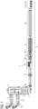
- the combined casting and rolling plant comprises two continuous casting plants 1a and 1b (of course, more than two continuous casting plants are also possible), which are connected to a rolling plant 5 via a slab manipulator 3 and a walking beam furnace 4.
- Liquid steel is cast into slabs 2 on each continuous casting plant 1a, 1b.
- the continuous casting plants each comprise a mold, an arcuate strand guide and a horizontal outlet area which is enclosed in thermal insulation 13.
- the slab strands of the continuous casting plants 1a and 1b are cut by shearing into slabs with a length of between 11.5 and 26 m, normally around 14 m.
- the produced slabs 2 are transported horizontally by the slab manipulator 3 into the gas-fired walking beam furnace 4, where they are heated to rolling temperature and transported to the rolling mill 5.
- the slab 2 is first descaled by a first descaling device 12a and then rolled into a pre-strip by a single-stand, reversing pre-rolling mill 6 through 3 to 5 rolling passes.
- the pre-strip is then wound up into a reel in the preferably thermally insulated coil box 7. After the coil box has been swiveled by 180°, the reel is unwound again and fed to the joining device 8.
- the pre-strips are partially descaled by a second descaling device 12b.
- a foot of a leading pre-strip is connected to the head of a trailing pre-strip to form an endless pre-strip (see also the Fig 3 ).
- the endless preliminary strip is then descaled by a third descaling device 12c and finish-rolled in the five-stand finishing mill to a finished strip with a final thickness of 0.8 mm.
- the finished strip is then cooled in the cooling section 10, cut by high-speed shears (or flying shears) and wound up by several - here, for example, three - coiling devices 11a... 11c.
- the pre-strip or the coiled pre-strip are thermally insulated.
- ⁇ 1a, 1b several continuous casting plants (here 1a, 1b) generate the necessary mass flow of 3.5 to 5.5 M t/a.
- the discrete slabs are heated to rolling temperature via the slab manipulator and the walking beam furnace and fed to the rolling plant 5.
- a slab 2 is first pre-rolled into a reel of a pre-strip.
- the reel is then unwound again and the head of the trailing, i.e. unwound, pre-strip is connected to the foot of a leading pre-strip to form an endless pre-strip.
- the connection is made by joining, specifically by pressing the pre-strips together without welding them together using a welding filler.
- the endless pre-strip is finish-rolled in the finishing mill in continuous operation, which means that ultra-thin hot strips with a thickness of ⁇ 1.2 mm, preferably even ⁇ 1.0 mm, can be easily produced.
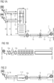
- the Fig 2 shows an elevation view of the casting-rolling composite plant from Fig 1 . It can be seen that the horizontal outlet areas of the two continuous casting plants 1a and 1b are approximately at the same height in the vertical direction as the inlet area of the rolling mill 5. However, no continuous casting plant is connected in-line to the rolling mill 5, since the slabs 2 are first brought into the rolling mill via the slab manipulator 3 and then the walking beam furnace 4. This ensures that the slabs have a constant temperature, regardless of whether they were produced in the first or second continuous casting plant 1a, 1b or even introduced externally into the slab manipulator. Specifically, the outlet area of the first continuous casting plant 1a has a larger offset A1 in the horizontal direction to the rolling mill 5 than the offset A2 in the horizontal direction between the outlet area of the second continuous casting plant 1b and the rolling mill 5.
- Fig 3 the steps in joining two pre-strips 20, 21 to form an endless pre-strip are shown.
- the head of the trailing pre-strip 21 is superimposed on the foot of the leading pre-strip 20, so that an overlapping area 23 is created.
- the pre-strips 20, 21 are then pressed together by pressing and piece forces 24, 25, with cutting edges 22 acting on the underside of the leading pre-strip 20 and the top side of the trailing pre-strip 21.
- pressing together and cutting off the pre-strips 20, 21 an endless pre-strip is created in the central area and two sections 26 above and below the central area.
- the sections are removed either mechanically or by fluid jets of the second descaling device 12b and finish rolled.
Landscapes
- Chemical & Material Sciences (AREA)
- Engineering & Computer Science (AREA)
- Mechanical Engineering (AREA)
- Physics & Mathematics (AREA)
- Thermal Sciences (AREA)
- Crystallography & Structural Chemistry (AREA)
- Materials Engineering (AREA)
- Metallurgy (AREA)
- Organic Chemistry (AREA)
- Metal Rolling (AREA)
Description
- Die vorliegende Erfindung betrifft das technische Gebiet der Eisen- und Stahlmetallurgie.
- Einerseits betrifft die Erfindung eine Gieß-Walz-Verbundanlage zur Herstellung von Warmband mit einer Enddicke < 1,2 mm.
- Andererseits betrifft die Erfindung ein Verfahren zur Herstellung von Warmband mit einer Enddicke < 1,2 mm auf einer Gieß-Walz-Verbundanlage.
- Gieß-Walz-Verbundanlagen zur Herstellung von Warmband durch die Kombination von Stranggießen und Warmwalzen sind bekannt, z.B. eine CSP Anlage der Fa. SMS, eine Arvedi ESP Anlage der Fa. Primetals Technologies oder eine QSP DUE Anlage der Fa. Danieli.
- Im Moment ist kein energieeffizientes Verfahren zur Herstellung von ultradünnen, warmgewalzten Bändern mit einer Produktionskapazität von > 3 Millionen Tonnen/Jahr (kurz 3 M t/a) verfügbar. Arvedi ESP Anlagen besitzen eine maximale Kapazität von ca. 3 M t/a. Um stabile Gießbedingungen sicherzustellen, ist eine Erhöhung der Kapazität mit derzeit verfügbaren Mitteln nicht möglich. Die Gießgeschwindigkeit ist auf ca. 6 m/min, der Durchsatz auf 6-8 t/min limitiert. Eine weitere Gießanlage kann nicht in den Endlosbetrieb der kompakten Anlage eingebunden werden und ist daher keine Option.
- Traditionelle Warmwalzwerke (engl. hot strip mills, kurz HSM) können hohe Durchsätze erreichen, sind jedoch nicht in der Lage, ultradünnes Band (Enddicke < 1,2 mm) herzustellen. Im Fall von 2-Strang "Thin slab casting and rolling (TSCR)" Prozessen sind hohe Produktionsraten theoretisch möglich, jedoch wird die Kapazität bei der endlosen Herstellung von sehr dünnen Bändern dramatisch gesenkt, da nur ein Gießstrang verwendet werden kann.
- Anlagentypen für hohe Produktionskapazität sind:
- HSM: Sehr hohe Kapazität (> 4 M t/a), keine dünnen bzw. ultradünnen Bänder, da nur diskontinuierlicher Betrieb möglich;
- 2-Strang TSCR: Hohe Kapazität (> 3 M t/a) im diskontinuierlichen Betrieb, niedrige Kapazität (< 3 M t/a) im Endlosbetrieb.
- Aus den vorgenannten Gründen wird die Warmbandproduktion mit hohen Kapazitäten zurzeit mit klassischen Warmwalzwerken (HSM) oder 2-Strang TSCR Anlagen realisiert.
- HSM verwenden Brammen von konventionellen Stranggießanlagen, welche vor dem Warmumformen von der Umgebungstemperatur auf die gewünschte Umformtemperatur erhitzt werden müssen (hoher Energieverbrauch). Warmwalzwerke sind in der Lage viele Stahlgüten in großen Mengen zu verarbeiten. Einer ihrer größten Nachteile ist, dass die finalen Banddicken über 1,2 mm liegen müssen, um die gültigen Einzugsbedingung nicht zu verletzen. Die Produktion von ultradünnen Bändern erfordert somit immer einen nachgeschalteten Kaltwalzprozess.
- Bei 2-Strang TSCR Prozessen, wie CSP oder QSP/DUE, sind zwei Stranggießanlagen durch Tunnelöfen mit der Warmwalzstraße verbunden; die Gießhitze wird ausgenutzt und hohe Kapazitäten sind theoretisch (abhängig vom Produktportfolio) möglich. Ein großer Nachteil liegt in Kapazitätseinbrüchen bei der Produktion von dünnem bzw. ultradünnem Band. Durch das Endlosverfahren wird ein Gießstrang von der Walzstraße entkoppelt und die Ausbringung sinkt um 50%.
- Aus der
DE 197 32 538 A1 ist eine Gieß-Walz-Verbundanlage zur Herstellung von Warmband mit einer Enddicke < 1,0 mm bekannt, aufweisend eine erste und eine zweite Stranggießanlage 2, 2' zum Vergießen von flüssigem Stahl zu Brammen, ein erster Rollherdofen 4 zum Erhitzen der Brammen von der ersten Stranggießanlage 2 auf Walztemperatur und ein separater zweiter Rollherdofen 4' zum Erhitzen der Brammen von der zweiten Stranggießanlage 2' auf Walztemperatur, und eine Fähre 5 zum Einschleusen von Brammen von der zweiten Stranggießanlage 2' in den ersten Rollherdofen 4. Die Brammen werden anschließend in einer reversierenden Gerüstgruppe 7 zu einem Vorband vorgewalzt und in einem Steckelofen aufgewickelt. Anschließend werden die Vorbänder durch eine Schweißmaschine zu einem endlosen Vorband zusammengeschweißt und in der Fertigstraße 15 fertiggewalzt. Da die Brammen der ersten und zweiten Stranggießanlage 2, 2' in den Rollherdöfen unterschiedlich erhitzt werden, eignet sich die Anlage nicht zur Herstellung von qualitativ hochwertigem Warmband. - Die Aufgabe der Erfindung besteht darin, eine neuartige Gieß-Walz-Verbundanlage zur Herstellung von Warmband mit einer Enddicke < 1,2 mm, vorzugsweise ≤ 1,0 mm, zu schaffen, sowie ein Verfahren zur Herstellung eines Warmbands mit einer Enddicke < 1,2 mm, vorzugsweise ≤ 1,0 mm, auf einer Gieß-Walz-Verbundanlage anzugeben, bei denen hochqualitatives ultradünnes Warmband mit hoher Kapazität, d.h. mit einer Kapazität zwischen 3,5 und 5,5 M t/a, durch Stranggießen und Warmwalzen auf der Gieß-Walz-Verbundanlage erzeugt werden kann.
- Der die Gieß-Walz-Verbundanlage betreffende Teil der Erfindung wird durch eine Gieß-Walz-Verbundanlage nach Anspruch 1 gelöst. Bevorzugte Ausführungsformen sind Gegenstand der abhängigen Ansprüche.
- Konkret erfolgt die Lösung durch eine Gieß-Walz-Verbundanlage zur Herstellung von Warmband mit einer Enddicke < 1,2 mm, vorzugsweise ≤ 1,0 mm, aufweisend
- zumindest eine erste Stranggießanlage und eine zweite Stranggießanlage, wobei jede Stranggießanlage flüssigen Stahl zu Brammen vergießt;
- einen Brammenmanipulator zum Transportieren der Brammen von den Stranggießanlagen in einen Hubbalkenofen zum Transportieren der Brammen vom Brammenmanipulator in eine Walzanlage und zum Erhitzen der Brammen auf Walztemperatur, wobei Brammen von der ersten Stranggießanlage und Brammen von der zweiten Stranggießanlage den Hubbalkenofen vollständig durchlaufen und dabei gleichmäßig erhitzt werden;
- die Walzanlage, umfassend
- -- ein Vorwalzwerk zum Vorwalzen der erhitzten Brammen zu einem Vorband,
- -- eine, vorzugsweise thermisch isolierte, Coilbox zum Aufwickeln des Vorbands zu einem Haspel und zum Abwickeln des Vorbands,
- -- eine Fügeeinrichtung zum Verbinden ohne Schweißzusatzstoff eines Fußes eines voreilenden Vorbands mit einem Kopf eines nacheilenden Vorbands zu einem endlosen Vorband,
- -- ein mehrgerüstiges Fertigwalzwerk zum Fertigwalzen des endlosen Vorbands zu einem Fertigband mit der Enddicke,
- -- eine Kühlstrecke zum Abkühlen des Fertigbands zu dem Warmband, und
- -- mehrere Haspeleinrichtungen zum Aufhaspeln des Warmbands, wobei das Vorwalzwerk, die Coilbox, die Fügeeinrichtung, das mehrgerüstige Fertigwalzwerk, die Kühlstrecke und die Haspeleinrichtungen der Walzanlage hintereinander in-line angeordnet sind und die erste Stranggießanlage einen ersten Versatz in einer ersten Richtung zur Walzanlage und die zweite Stranggießanlage einen zweiten Versatz in der ersten Richtung zur Walzanlage aufweist.
- Erfindungsgemäß weist die Gieß-Walz-Verbundanlage zumindest zwei separate Stranggießanlagen mit jeweiligen separaten Kokillen und bogenförmigen Strangführungen auf. Das Stranggießen von zwei oder drei Strängen (engl. twin- oder triple-casting) mittels einer geteilten Kokille auf einer Stranggießanlage ist nicht erfindungsgemäß, da keine separaten Stranggießanlagen vorhanden sind. Jede Stranggießanlage vergießt flüssigen Stahl zu Brammen. Die Brammen können Dünn- oder Mittelbrammen mit einer Dicke von 140 bis 240 mm und einer Breite zwischen 1100 bis 2300 mm sein. Die Brammenlänge beträgt typischerweise zwischen 11,5 und 26 m. Die auf den Stranggießanlagen produzierten Brammen werden wärmeisoliert einem Brammenmanipulator zugeführt, der die Brammen von den Stranggießanlagen in einen Hubbalkenofen bringt. Im, z.B. gas- oder ölbefeuerten, Hubbalkenofen werden die Brammen von den Stranggießanlagen gleichmäßig auf Walztemperatur erhitzt und zu einer Walzanlage gebracht. Alle Brammen durchlaufen den Hubbalkenofen von einem Eingangsbereich in einen Ausgangsbereich des Hubbalkenofens vollständig, und zwar unabhängig vom Ursprung (d.h. ob sie von der ersten oder der zweiten Stranggießanlage kommen) der Brammen. Der Hubbalken weist mehrere Hubbalken auf, die die Bramme anheben und ein Stück weiter in Transportrichtung wieder ablegen. Dadurch wird die Bramme durch den Hubbalkenofen transportiert. Im Gegensatz dazu, weist ein Rollherdofen Rollen auf, die die Bramme durch "Rollen" durch den Ofen transportieren. Hubbalkenöfen sind sehr robust und verschleißarm; hingegen sind die Rollen und insbesondere die Lager der Rollen bei Rollherdöfen einem signifikanten Verschleiß bei Temperaturen ≥ 1000 °C unterworfen. Die Walzanlage umfasst ein Vorwalzwerk zum Vorwalzen der erhitzten Brammen zu einem Vorband, eine, vorzugsweise thermisch isolierte, Coilbox zum Aufwickeln des Vorbands zu einem Haspel und zum Abwickeln des Vorbands, eine Fügeeinrichtung zum Verbinden ohne Schweißzusatzwerkstoff eines Fußes eines voreilenden Vorbands mit einem Kopf eines nacheilenden Vorbands zu einem endlosen Vorband, ein mehrgerüstiges Fertigwalzwerk zum Fertigwalzen des endlosen Vorbands zu einem Fertigband mit der Enddicke, eine Kühlstrecke zum Abkühlen des Fertigbands zu dem Warmband, und mehrere Haspeleinrichtungen zum Aufhaspeln des Warmbands. Das Vorwalzwerk, die Coilbox, die Fügeeinrichtung, das mehrgerüstige Fertigwalzwerk, die Kühlstrecke und die Haspeleinrichtungen der Walzanlage sind hintereinander in-line angeordnet. Die erste Stranggießanlage weist einen ersten Versatz in einer ersten Richtung zur Walzanlage und die zweite Stranggießanlage weist einen zweiten Versatz, der kleiner oder größer dem ersten Versatz ist, in der ersten Richtung zur Walzanlage auf. Da alle Brammen den Hubbalkenofen durchlaufen, weisen die Brammen eine relativ konstante Temperatur am Ausgang des Hubbalkenofens auf. Nach dem Hubbalkenofen werden die erhitzten Brammen im Vorwalzwerk zu einem Vorband vorgewalzt. Bevorzugt ist das Vorwalzwerk ein eingerüstiges, reversierendes Vorwalzwerk. Alternativ dazu kann das Vorwalzwerk auch mehrgerüstig ausgeführt sein, z.B. mit einem zweiten Gerüst.
- Nach dem Vorwalzen wird das Vorband in einer Coilbox aufgewickelt. Nach dem Abwickeln des Vorbands wird ein Fuß eines voreilenden Vorbands mit einem Kopf eines nacheilenden Vorbands zu einem endlosen Vorband in einer Fügeeinrichtung verbunden. Das endlose Vorband wird dann in einem mehrgerüstigen Fertigwalzwerk (bspw. mit 5, 6 oder 7 Fertigwalzgerüsten) zu einem Fertigband mit der Enddicke fertiggewalzt, in einer Kühlstrecke zu dem Warmband abgekühlt und durch mehrere Haspeleinrichtungen aufgewickelt. Vor dem Aufwickeln in den Haspeleinrichtungen wird das Warmband durch eine sog. "high speed shear" geschnitten.
- Das Problem der niedrigen Produktionskapazität bei den Anlagen nach dem Stand der Technik wird durch mehrere Gießstränge gelöst. Eine Mehrstranggießanlage oder mehrere einzelne Gießanlagen (Dünnbrammen oder konventionelle Brammen) sind über einen Hubbalkenofen mit der Walzstraße verbunden. Die Temperatur der chargierten Brammen liegt im Normalbetrieb und abhängig von den Gießparametern 900-1100°C. Die Austragstemperaturen aus dem Hubbalkenofen betragen typischerweise zwischen 1050 und 1200°C, um die gewünschte Umformung realisieren zu können. Das Heißeinsetzen wird mittels eines Brammenmanipulators durchgeführt, welcher flexibel zwischen den beiden Strängen operieren kann. Außerdem ist es möglich, Brammen vor dem Ofen aus dem Prozess auszuführen oder sie in den Prozess einzusetzen. Dadurch wird der Gießbetrieb durch Stillstände in der Walzanlage nicht beeinflusst und der Kalteinsatz von Brammen sichergestellt. Keine der Gießanlagen soll in Linie (in-line) mit der Walzstraße positioniert werden, wodurch die gleiche Erwärmung für alle Brammen (konstante Walzbedingungen, gleichmäßige Bandeigenschaften, hohe Qualität) und eine einfachere Produktionsplanung ermöglicht wird. Die Vorwalzstraße besteht vorzugsweise aus einem reversierenden Walzgerüst. Für höhere Kapazitäten kann ein weiteres Gerüst (z.B. Duo-Walzgerüst) hinzugefügt werden. Optional kann der Vorstraße ein Edger vorgelagert werden, um die Bandbreite einzustellen. Die Walzstraße wird für geringe Banddicken unter 1,2 mm ausgelegt. Dazu weist die Walzstraße eine "Coil-box" und eine Fügeeinrichtung (auch engl. Super deformation joiner, kurz SDJ, genannt) auf. Der SDJ verbindet die Zwischenbänder miteinander, wodurch die Fertigstraße im Endlosbetrieb, mit all seinen Vorteilen (konstante Prozessbedingungen, gleichmäßige Eigenschaften, Walzdicken < 1,2 mm) gefahren werden kann. Somit ist es möglich, die Produktion von zwei oder mehreren Strängen in nur einer Fertigstraße endlos zu betreiben. Alle Bereiche zwischen den einzelnen Aggregaten werden vorzugsweise thermisch isoliert, um ein Maximum an Wärmeenergie zu konservieren.
- Beim Herstellverfahren sind die Stranggießanlagen mit der Walzanlage abgestimmt um die gewünschte Produktionskapazität von 3,5-5,5 M t/a im Endlosbetrieb darzustellen. Um die Kapazitäten bei einer spezifischen Masse pro Coil von 18-21 kg/mm zu erreichen, soll eine Coil-Folgezeit von 2-4 min realisiert werden. Die Stranggießanlagen weisen bevorzugt eine Produktionsrate von 9-14 t/min auf.
- Um die genannten Kapazitäten im Endlosbetrieb umzusetzen, müssen weitere Randbedingungen bedacht werden. Abhängig von der Brammendicke sind 3-5 Stiche in der Vorstraße vorteilhaft, um eine gewünschte Zwischenbanddicke von 25-35 mm zu erreichen. Vom Beginn der Walzstraße bis zum aufgewickelten Zwischenband in der Coil-box (Zykluszeit der Vorwalzsequenz) vergehen ca. 100-220 s. Bis der Fuß des Zwischenbands die Coil-box wieder verlässt (Zykluszeit pro Band in der Fertigstraße), braucht es typischerweise 140-250 s. Daraus ergibt sich eine minimal notwendige Austragsrate aus dem Hubbalkenofen von 0,2-0,4 Brammen pro Minute oder 6-13 t/min. Dieser Massenfluss wird von den Stranggießanlagen erreicht, um den Endlosbetrieb der Fertigstraße aufrechtzuerhalten. Wie oben gezeigt, wird das durch die erwähnten Gießparameter problemlos erreicht. Den wesentlichen Regelparameter der Anlage stellt die Walzendtemperatur dar, welche u.a. über die Walzgutgeschwindigkeit kontrolliert wird. Zusätzliche Kühleinrichtungen in der Fertigstraße ermöglichen eine maximale Walzgutgeschwindigkeit von 15-20 m/s. Im Endlosbetrieb gibt somit die Fertigstraße den Massenfluss vor. Alle Aggregate von der Vorstraße, über den Hubbalkenofen, den Brammenmanipulator bis zu den Gießanlagen sind so dimensioniert, dass sie diesem Produktionstakt folgen.
- Typische Bedingungen zum Erreichen einer Produktionskapazität von 3,5-5,5 M t/a im Endlosbetrieb:
- - Zykluszeit pro Band in der Fertigstraße ist definiert über den Massenfluss (9-14 t/h)
- - Zykluszeit der Vorwalzsequenz (Bandfolgezeit) ≤ Zykluszeit pro Band in der Fertigstraße
- - Min. Austragsrate des Hubbalkenofens ≤ Zykluszeit der Vorwalzsequenz
- - Gießzeit pro Bramme ≤ Min. Austragsrate des Hubbalkenofens
- Kurzzeitige Abweichungen von diesen Bedingungen können über einen aufgebauten Puffer im Hubbalken und oder der Coil-box kompensiert werden. Im Ausnahmefall (Stillstand der Walzstraße) muss der Gießprozess nicht unterbrochen werden. Brammen können im Hubbalkenofen gepuffert oder bei längeren Unterbrechungen vor dem Ofen aus dem Prozess ausgeschleust werden. Später können sie an dieser Stelle wieder in den Prozess zugeführt werden. Neben der hohen Kapazität sollen hohe Qualitätsansprüchen und niedrige Energieverbräuche erfüllt werden. Der Energieverbrauch wird durch eine optimierte Sekundärkühlstrategie auf ein Minimum reduziert. Dabei ist es vorteilhaft, die Ofeneinsatztemperatur über 900 °C zu halten, um den Gasverbrauch des Hubbalkenofens zu senken. Kühlstrategie und Brammentemperatur müssen jedoch immer in Abstimmung mit der Brammenqualität gewählt werden. Ein weiteres Hauptaugenmerk liegt auf der räumlichen Nähe der Gießanlagen zum Hubbalkenofen und zur Walzstraße, sodass ein möglichst geringer Wärmeverlust ermöglicht wird. Mit dem Hubbalkenofen können im Vergleich zu anderen Ofentypen, wie etwa dem Tunnelofen, bessere Oberflächenqualitäten erreicht werden. In Kombination mit dem Brammenmanipulator zeichnet er sich auch durch eine flexible Produktionsplanung aus. Die Stränge können flexibel, je nach aktueller Verfügbarkeit, bedient werden, ohne den jeweils anderen Strang zu beeinflussen.
- Die wesentlichen Vorteile der erfindungsgemäßen Lösung sind:
- - Hohe Produktionskapazität von > 3 M t/a im Endlosbetrieb,
- - Endloswalzen für Banddicken <1, 2 mm,
- - Heißeinsatz von Brammen reduziert den Energieverbrauch im Vergleich zu konventionellen Warmwalzstraßen, und
- - Dickere Brammen ermöglichen die Verarbeitung von IF Stahl und peritektischen Güten.
- Vorzugsweise ist die erste Richtung die Horizontale, d.h. dass der Auslaufbereich der ersten Stranggießanlage, der Auslaufbereich der zweiten Stranggießanlage und die Walzanlage sind in horizontaler Richtung nebeneinander angeordnet. Der Brammenmanipulator verbindet die Auslaufbereiche der Stranggießanlagen mit einem Eingangsbereich des Hubbalkenofens, sodass ein horizontaler Abstand zwischen dem Auslaufbereich der ersten Stranggießanlage und der Walzanlage größer ist als ein horizontaler Abstand zwischen dem Auslaufbereich der zweiten Stranggießanlage und der Walzanlage.
- Bevorzugt weist das Fertigwalzwerk 5, 6 oder 7 Fertigwalzgerüste auf.
- Bevorzugt ist außerdem, dass nach dem Hubbalkenofen und vor dem Vorwalzwerk eine erste Entzunderungseinrichtung angeordnet ist und/oder dass vor der Fügeeinrichtung und vor dem Fertigwalzwerk eine zweite und eine dritte Entzunderungseinrichtung angeordnet ist. Hierbei entzundert die erste Entzunderungseinrichtung die erhitzten Brammen, die zweite Entzunderungseinrichtung entzundert partiell die Vorbänder vor dem Fügen zu einem endlosen Vorband und die dritte Entzunderungseinrichtung entzundert die Vorbänder vor dem Fertigwalzen.
- Um den Produktionsbetrieb auch bei Unterbrechungen einerseits der Walzanlage und andererseits einer Stranggießanlage aufrechterhalten zu können, ist es vorteilhaft, dass der Brammenmanipulator von den Stranggießanlagen erzeugte Brammen quer zur Transportrichtung von den Stranggießanlagen zum Hubbalkenofen ausschleusen kann und der Brammenmanipulator Brammen, die nicht in den Stranggießanlagen der Gieß-Walz-Verbundanlage erzeugt wurden, quer zur Transportrichtung von den Stranggießanlagen zum Hubbalkenofen einschleusen kann.
- Der das Herstellverfahren betreffende Teil der Erfindung wird durch ein Verfahren zur Herstellung eines Warmbands mit einer Enddicke < 1,2 mm auf einer Gieß-Walz-Verbundanlage nach Anspruch 8 gelöst. Bevorzugte Ausführungsformen sind Gegenstand der abhängigen Ansprüche.
- Konkret erfolgt die Lösung durch ein Verfahren zur Herstellung eines Warmbands mit einer Enddicke < 1,2 mm, vorzugsweise ≤ 1,0 mm, auf einer Gieß-Walz-Verbundanlage, insbesondere nach einem der vorhergehenden Ansprüche, aufweisend folgende Schritte:
- - Stranggießen von flüssigem Stahl zu Brammen auf zumindest einer ersten Stranggießanlage und einer zweiten Stranggießanlage;
- - Transportieren der Brammen von den Stranggießanlagen in einen Eingangsbereich eines Hubbalkenofens;
- - Transportieren der Brammen vom Eingangsbereich durch den Hubbalkenofen in einen Ausgangsbereich des Hubbalkenofens, wobei die Brammen auf Walztemperatur erhitzt werden;
- - Vorwalzen der erhitzten Brammen zu einem Vorband;
- - Aufwickeln des Vorbands zu einem Haspel und vorzugsweise thermisches Isolieren, besonders bevorzugt Erhitzen, des Haspels;
- - Abwickeln des Vorbands vom Haspel;
- - Verbinden eines Fußes eines voreilenden Vorbands mit einem Kopf eines nacheilenden Vorbands zu einem endlosen Vorband;
- - Fertigwalzen des endlosen Vorbands zu einem Fertigband mit der Enddicke durch mehrere Walzstiche in einem mehrgerüstigen Fertigwalzwerk;
- - Abkühlen des Fertigbands zu dem Warmband;
- - Abschneiden des Warmbands; und
- - Aufhaspeln des Warmbands.
- Vorzugsweise erfolgt das Vorwalzen durch mehrere, vorzugsweise 3-5, Walzstiche in einem reversierenden Vorwalzwerk.
- Beim Verbinden der Vorbänder zu dem endlosen Vorband wird vorzugsweise zuerst der Fuß des voreilenden Vorbands mit einem Kopf des nacheilenden Vorbands überlappt, und anschließend der überlappende Bereich der Vorbänder verpresst, wobei die vertikale Position der Vorbänder aneinander angeglichen werden.
- Um eine hohe Produktivität erreichen zu können, ist es günstig, wenn die Brammen eine Dicke von 140 bis 240 mm und einer Breite zwischen 1100 bis 2300 mm aufweisen und/oder das Vorband eine Dicke zwischen 25 und 35 mm aufweist.
- Der Gesamtenergieverbrauch des Herstellverfahren ist niedrig, wenn die Brammen mit einer Temperatur ≥ 900 °C in den Hubbalkenofen eingesetzt werden.
- Ein ausfallsarmer Betrieb der Stranggießanlagen wird gewährleistet, wenn die Stranggießanlagen Brammen mit einer Dicke von 150 bis 190 mm bei einer Gießgeschwindigkeit von 4 bis 5 m/min und Brammen mit einer Dicke von 191 bis 230 mm bei einer Gießgeschwindigkeit von 2 bis 4 m/min produzieren.
- Die oben beschriebenen Eigenschaften, Merkmale und Vorteile dieser Erfindung sowie die Art und Weise, wie diese erreicht werden, werden klarer und deutlicher verständlich im Zusammenhang mit der folgenden Beschreibung eines Ausführungsbeispiels, das im Zusammenhang mit den Zeichnungen näher erläutert wird. Dabei zeigen:
-
Fig 1 ein schematisches Schema einer Gieß-Walz-Verbundanlage, -
Fig 1a ein vorderer Abschnitt der Gieß-Walz-Verbundanlage ausFig 1 , -
Fig 1b ein mittlerer Abschnitt der Gieß-Walz-Verbundanlage ausFig 1 , -
Fig 2 eine Aufrissdarstellung der Gieß-Walz-Verbundanlage ausFig 1 , und -
Fig 3 eine schematische Darstellung der Schritte beim Fügen von zwei Vorbändern zu einem endlosen Vorband. - In den
Fig 1 ,1a und 1b ist die erfindungsgemäße Gieß-Walz-Verbundanlage schematisch dargestellt. Die Gieß-Walz-Verbundanlage umfasst zwei Stranggießanlagen 1a und 1b (es sind natürlich auch mehr als zwei Stranggießanlagen möglich), die über einen Brammenmanipulator 3 und einen Hubbalkenofen 4 mit einer Walzanlage 5 verbunden sind. Auf jeder Stranggießanlage 1a, 1b wird flüssiger Stahl zu Brammen 2 vergossen. Die Stranggießanlagen umfassen jeweils eine Kokille, eine bogenförmige Strangführung und einen horizontalen Auslaufbereich, der in einer thermischen Isolierung 13 eingehaust ist. Die Brammenstränge der Stranggießanlagen 1a und 1b werden durch Scheren auf Brammen mit einer Länge zwischen 11,5 und 26 m, normalerweise ca. 14 m, geschnitten. Die produzierten Brammen 2 werden durch den Brammenmanipulator 3 in horizontaler Richtung in den gasbefeuerten Hubbalkenofen 4 transportiert, dort auf Walztemperatur erhitzt und zur Walzanlage 5 transportiert. - Im Eingangsbereich der Walzanlage 5 wird die Bramme 2 zuerst durch eine erste Entzunderungseinrichtung 12a entzundert und anschließend durch ein eingerüstiges, reversierendes Vorwalzwerk 6 durch 3 bis 5 Walzstiche zu einem Vorband gewalzt. Anschließend wird das Vorband in der, vorzugsweise thermisch isolierten, Coilbox 7 zu einem Haspel aufgewickelt. Nach dem Verschwenken der Coilbox um 180° wird der Haspel wieder abgewickelt und der Fügeeinrichtung 8 zugeführt. Um eine sichere Verbindung der Vorbänder zu gewährleisten, werden die Vorbänder durch eine zweite Entzunderungseinrichtung 12b partiell entzundert. In der Fügeeinrichtung 8 wird ein Fuß eines voreilenden Vorbands mit dem Kopf eines nacheilenden Vorbands zu einem endlosen Vorband verbunden (siehe auch die
Fig 3 ). - Das endlose Vorband wird anschließend durch eine dritte Entzunderungseinrichtung 12c entzundert und im fünfgerüstigen Fertigwalzwerk zu einem Fertigband mit der Enddicke von 0,8 mm fertiggewalzt. Anschließend wird das Fertigband in der Kühlstrecke 10 abgekühlt, durch eine Hochgeschwindigkeitsschere (engl. high speed shears oder flying shears) abgeschnitten und durch mehrere - hier z.B. drei - Haspeleinrichtungen 11a... 11c aufgewickelt.
- Zwischen der ersten Entzunderungseinrichtung 12a und dem Vorwalzwerk 6, dem Vorwalzwerk 6 und der Coilbox 7 sowie im Bereich der Coilbox 7 werden die Brammen 2, das Vorband bzw. das aufgehaspelte Vorband thermisch isoliert. Je nach produzierter Stahlgüte kann es außerdem notwendig sein, das Warmband in der Kühlstrecke 10 nicht abzukühlen, sondern thermisch zu isolieren.
- Gemäß der Erfindung erzeugen mehrere Stranggießanlagen (hier 1a, 1b) den notwendigen Massenfluss von 3,5 bis 5,5 M t/a. Die diskreten Brammen werden über den Brammenmanipulator und den Hubbalkenofen auf Walztemperatur erhitzt und der Walzanlage 5 zugeführt. In der Walzanlage 5 wird aus einer Bramme 2 durch Vorwalzen zuerst ein Haspel eines Vorbands erzeugt. Anschließend wird der Haspel wieder abgewickelt und der Kopf des nacheilenden, d.h. abgewickelten, Vorbands mit dem Fuß eines voreilenden Vorbands zu einem endlosen Vorband verbunden. Das Verbinden erfolgt durch Fügen, konkret durch Verpressen der Vorbänder, ohne diese durch einen Schweißzusatzstoff miteinander zu verschweißen. Das endlose Vorband wird im Endlosbetrieb in der Fertigwalzstraße fertiggewalzt, wodurch problemlos ultradünne Warmbänder mit einer Dicke < 1,2 mm, bevorzugt sogar ≤ 1,0 mm, erzeugt werden können.
- Die
Fig 2 zeigt eine Aufrissdarstellung der Gieß-Walz-Verbundanlage ausFig 1 . Zu sehen ist, dass die horizontalen Auslaufbereiche der beiden Stranggießanlagen 1a und 1b in vertikaler Richtung in etwa auf derselben Höhe liegen als der Eingangsbereich der Walzanlage 5. Allerdings ist keine Stranggießanlage in-line mit der Walzanlage 5 verbunden, da die Brammen 2 zuerst über den Brammenmanipulator 3 und dann den Hubbalkenofen 4 in die Walzanlage verbracht werden. Dadurch wird sichergestellt, dass die Brammen eine konstante Temperatur aufweisen, unabhängig davon, ob sie in der ersten oder der zweiten Stranggießanlage 1a, 1b hergestellt wurden oder gar extern in den Brammenmanipulator eingebracht wurden. Konkret weist der Auslaufbereich der ersten Stranggießanlage 1a einen größeren Versatz A1 in horizontaler Richtung zur Walzanlage 5 auf als der Versatz A2 in horizontaler Richtung zwischen dem Auslaufbereich der zweiten Stranggießanlage 1b und der Walzanlage 5. - In
Fig 3 sind die Schritte beim Fügen von zwei Vorbändern 20, 21 zu einem endlosen Vorband dargestellt. Zuerst wird der Kopf des nacheilenden Vorbands 21 mit dem Fuß des voreilenden Vorbands 20 überlagert, sodass ein überlappender Bereich 23 entsteht. Anschließend werden die Vorbänder 20, 21 durch Press- und Stückkräfte 24, 25 aneinandergepresst, wobei auf der Unterseite des voreilenden Vorbands 20 und der Oberseite des nacheilenden Vorbands 21 Schneidekanten 22 einwirken. Durch das Zusammenpressen und Abschneiden der Vorbänder 20, 21 entsteht im zentralen Bereich ein endloses Vorband und zwei Abschnitte 26 ober- und unterhalb des zentralen Bereichs. - Die Abschnitte werden entweder mechanisch oder durch Fluidstrahlen der zweiten Entzunderungseinrichtung 12b entfernt und fertiggewalzt.
- Obwohl die Erfindung im Detail durch die bevorzugten Ausführungsbeispiele näher illustriert und beschrieben wurde, so ist die Erfindung nicht durch die offenbarten Beispiele eingeschränkt und andere Variationen können vom Fachmann hieraus abgeleitet werden, ohne den durch die Ansprüche definierten Schutzumfang der Erfindung zu verlassen.
-
- 1
- Stranggießanlage
- 1a
- erste Stranggießanlage
- 1b
- zweite Stranggießanlage
- 2
- Bramme
- 3
- Brammenmanipulator
- 4
- Hubbalkenofen
- 5
- Walzanlage
- 6
- Vorwalzwerk
- 7
- Coilbox
- 8
- Fügeeinrichtung
- 9
- Fertigwalzwerk
- 10
- Kühlstrecke
- 11a... 11c
- Haspeleinrichtung
- 12a
- erste Entzunderungseinrichtung
- 12b
- zweite Entzunderungseinrichtung
- 12c
- dritte Entzunderungseinrichtung
- 13
- Thermische Isolierung
- 20
- voreilendes Vorband
- 21
- nacheilendes Vorband
- 22
- Schneidekante
- 23
- Überlappender Bereich der Vorbänder
- 24
- Presskraft
- 25
- Stützkraft
- 26
- Abschnitte
- A1, A2
- erster Versatz, zweiter Versatz
Claims (15)
- Gieß-Walz-Verbundanlage zur Herstellung von Warmband mit einer Enddicke < 1,2 mm, vorzugsweise ≤ 1,0 mm, aufweisend- zumindest eine erste Stranggießanlage (1a) und eine zweite Stranggießanlage (1b), wobei jede Stranggießanlage (1a, 1b) flüssigen Stahl zu Brammen (2) vergießt;- einen Brammenmanipulator (3) zum Transportieren der Brammen (2) von den Stranggießanlagen (1a, 1b) in einen Hubbalkenofen (4)
zum Transportieren der Brammen (2) vom Brammenmanipulator (3) in eine Walzanlage (5) und zum Erhitzen der Brammen (2) auf Walztemperatur, wobei Brammen (2) von der ersten Stranggießanlage (1a) und Brammen (2) von der zweiten Stranggießanlage (1b) den Hubbalkenofen (4) vollständig durchlaufen und dabei gleichmäßig erhitzt werden;- die Walzanlage (5), umfassend-- ein Vorwalzwerk (6) zum Vorwalzen der erhitzten Brammen (2) zu einem Vorband,-- eine, vorzugsweise thermisch isolierte, Coilbox (7) zum Aufwickeln des Vorbands zu einem Haspel und zum Abwickeln des Vorbands,-- eine Fügeeinrichtung (8) zum Verbinden ohne Schweißzusatzstoff eines Fußes eines voreilenden Vorbands (20) mit einem Kopf eines nacheilenden Vorbands (21) zu einem endlosen Vorband,-- ein mehrgerüstiges Fertigwalzwerk (9) zum Fertigwalzen des endlosen Vorbands zu einem Fertigband mit der Enddicke,-- eine Kühlstrecke (10) zum Abkühlen des Fertigbands zu dem Warmband, und-- mehrere Haspeleinrichtungen (11a... 11c) zum Aufhaspeln des Warmbands, wobei das Vorwalzwerk (6), die Coilbox (7), die Fügeeinrichtung (8), das mehrgerüstige Fertigwalzwerk (9), die Kühlstrecke (10) und die Haspeleinrichtungen (11a... 11c) der Walzanlage (5) hintereinander in-line angeordnet sind und die erste Stranggießanlage (1a) einen ersten Versatz (A1) in einer ersten Richtung zur Walzanlage (5) und die zweite Stranggießanlage (1b) einen zweiten Versatz (A2) in der ersten Richtung zur Walzanlage (5) aufweist. - Gieß-Walz-Verbundanlage nach Anspruch 1, dadurch gekennzeichnet, dass die Stranggießanlagen (1a, 1b) zur Erzeugung von Brammen mit einer Dicke von 140 bis 240 mm und einer Breite zwischen 1100 bis 2300 mm konfiguriert sind.
- Gieß-Walz-Verbundanlage nach einem der vorhergehenden Ansprüche, dadurch gekennzeichnet, dass das Vorwalzwerk (6) ein reversierendes, vorzugsweise eingerüstiges, Vorwalzwerk ist.
- Gieß-Walz-Verbundanlage nach einem der vorhergehenden Ansprüche, dadurch gekennzeichnet, dass die erste Richtung die Horizontale ist.
- Gieß-Walz-Verbundanlage nach einem der vorhergehenden Ansprüche, dadurch gekennzeichnet, dass das Fertigwalzwerk (9) fünf bis sieben Fertigwalzgerüste aufweist.
- Gieß-Walz-Verbundanlage nach einem der vorhergehenden Ansprüche, dadurch gekennzeichnet, dass nach dem Hubbalkenofen (4) und vor dem Vorwalzwerk (6) eine erste Entzunderungseinrichtung (12a) angeordnet ist und/oder dass vor der Fügeeinrichtung (8) eine zweite Entzunderungseinrichtung (12b) und vor dem Fertigwalzwerk (9) eine dritte Entzunderungseinrichtung (12c) angeordnet ist.
- Gieß-Walz-Verbundanlage nach einem der vorhergehenden Ansprüche, dadurch gekennzeichnet, dass der Brammenmanipulator (3) von den Stranggießanlagen (1a, 1b) erzeugte Brammen (2) quer zur Transportrichtung von den Stranggießanlagen (1a, 1b) zum Hubbalkenofen (4) ausschleusen kann und der Brammenmanipulator (3) Brammen (2), die nicht in den Stranggießanlagen (1a, 1b) der Gieß-Walz-Verbundanlage erzeugt wurden, quer zur Transportrichtung von den Stranggießanlagen (1a, 1b) zum Hubbalkenofen (4) einschleusen kann.
- Verfahren zur Herstellung eines Warmbands mit einer Enddicke < 1,2 mm, vorzugsweise ≤ 1,0 mm, auf einer Gieß-Walz-Verbundanlage, insbesondere nach einem der vorhergehenden Ansprüche, aufweisend folgende Schritte:- Stranggießen von flüssigem Stahl zu Brammen (2) auf zumindest einer ersten Stranggießanlage (1a) und einer zweiten Stranggießanlage (1b);- Transportieren der Brammen (2) von den Stranggießanlagen (1a, 1b) in einen Eingangsbereich eines Hubbalkenofens (4);- Transportieren der Brammen (2) vom Eingangsbereich durch den Hubbalkenofen (4) in einen Ausgangsbereich des Hubbalkenofens (4), wobei die Brammen (2) auf Walztemperatur erhitzt werden;- Vorwalzen der erhitzten Brammen (2) zu einem Vorband;- Aufwickeln des Vorbands zu einem Haspel und vorzugsweise thermisches Isolieren, besonders bevorzugt Erhitzen, des Haspels;- Abwickeln des Vorbands vom Haspel;- Verbinden ohne Schweißzusatzstoff eines Fußes eines voreilenden Vorbands (20) mit einem Kopf eines nacheilenden Vorbands (21) zu einem endlosen Vorband;- Fertigwalzen des endlosen Vorbands zu einem Fertigband mit der Enddicke durch mehrere Walzstiche in einem mehrgerüstigen Fertigwalzwerk (9);- Abkühlen des Fertigbands zu dem Warmband;- Abschneiden des Warmbands; und- Aufhaspeln des Warmbands.
- Verfahren nach Anspruch 8, dadurch gekennzeichnet, dass das Vorwalzen durch mehrere, vorzugsweise 3-5, Walzstiche in einem reversierenden Vorwalzwerk (6) erfolgt.
- Verfahren nach einem der Ansprüche 8 bis 10, dadurch gekennzeichnet, dass beim Verbinden der Vorbänder zu dem endlosen Vorband zuerst der Fuß des voreilenden Vorbands (20) mit einem Kopf des nacheilenden Vorbands (21) überlappt wird, und anschließend der überlappende Bereich der Vorbänder (20, 21) verpresst wird, wobei die vertikale Position der Vorbänder (20, 21) aneinander angeglichen werden.
- Verfahren nach einem der Ansprüche 8 bis 10, dadurch gekennzeichnet, dass die Vorbänder (20, 21) nach dem Abwickeln und vor dem Verbinden entzundert werden.
- Verfahren nach einem der Ansprüche 8 bis 11, dadurch gekennzeichnet, dass die Brammen (2) eine Dicke von 140 bis 240 mm und eine Breite zwischen 1100 bis 2300 mm aufweisen und/oder das Vorband eine Dicke zwischen 25 und 35 mm aufweist.
- Verfahren nach einem der Ansprüche 8 bis 12, dadurch gekennzeichnet, dass die Brammen (2) mit einer Temperatur ≥ 900 °C in den Hubbalkenofen (4) eingesetzt werden.
- Verfahren nach einem der Ansprüche 8 bis 13, dadurch gekennzeichnet, dass die Gieß-Walz-Verbundanlage eine jährliche Produktionskapazität zwischen 3 und 6 Millionen Tonnen, insbesondere zwischen 3,5 und 5,5 Millionen Tonnen, aufweist.
- Verfahren nach einem der Ansprüche 8 bis 14, dadurch gekennzeichnet, dass die Stranggießanlagen (1a, 1b) Brammen (2) mit einer Dicke von 150 bis 190 mm bei einer Gießgeschwindigkeit von 4 bis 5 m/min und Brammen (2) mit einer Dicke von 191 bis 230 mm bei einer Gießgeschwindigkeit von 2 bis 4 m/min produzieren.
Applications Claiming Priority (2)
| Application Number | Priority Date | Filing Date | Title |
|---|---|---|---|
| EP21159381.9A EP4049768A1 (de) | 2021-02-25 | 2021-02-25 | Giess-walz-verbundanlage und verfahren zur herstellung von warmband mit einer enddicke kleiner als 1,2 mm auf der giess-walz-verbundanlage |
| PCT/EP2022/053671 WO2022179890A1 (de) | 2021-02-25 | 2022-02-15 | Giess-walz-verbundanlage und verfahren zur herstellung von warmband mit einer enddicke <1,2 mm auf der giess-walz-verbundanlage |
Publications (3)
| Publication Number | Publication Date |
|---|---|
| EP4297918A1 EP4297918A1 (de) | 2024-01-03 |
| EP4297918B1 true EP4297918B1 (de) | 2025-01-29 |
| EP4297918C0 EP4297918C0 (de) | 2025-01-29 |
Family
ID=74758699
Family Applications (2)
| Application Number | Title | Priority Date | Filing Date |
|---|---|---|---|
| EP21159381.9A Withdrawn EP4049768A1 (de) | 2021-02-25 | 2021-02-25 | Giess-walz-verbundanlage und verfahren zur herstellung von warmband mit einer enddicke kleiner als 1,2 mm auf der giess-walz-verbundanlage |
| EP22708862.2A Active EP4297918B1 (de) | 2021-02-25 | 2022-02-15 | Giess-walz-verbundanlage und verfahren zur herstellung von warmband mit einer enddicke <1,2 mm auf der giess-walz-verbundanlage |
Family Applications Before (1)
| Application Number | Title | Priority Date | Filing Date |
|---|---|---|---|
| EP21159381.9A Withdrawn EP4049768A1 (de) | 2021-02-25 | 2021-02-25 | Giess-walz-verbundanlage und verfahren zur herstellung von warmband mit einer enddicke kleiner als 1,2 mm auf der giess-walz-verbundanlage |
Country Status (4)
| Country | Link |
|---|---|
| US (1) | US20240100590A1 (de) |
| EP (2) | EP4049768A1 (de) |
| CN (1) | CN116887930A (de) |
| WO (1) | WO2022179890A1 (de) |
Families Citing this family (4)
| Publication number | Priority date | Publication date | Assignee | Title |
|---|---|---|---|---|
| DE102023135962A1 (de) * | 2023-08-28 | 2025-03-06 | Sms Group Gmbh | Warmwalzvorrichtung und Verfahren zum Warmwalzen sowie Anlage zur Herstellung und/oder Verarbeitung eines metallischen Gutes |
| CN117324376A (zh) * | 2023-10-24 | 2024-01-02 | 甘肃酒钢集团宏兴钢铁股份有限公司 | 一种适用于板带轧机生产高锰无磁钢的方法 |
| WO2025131410A1 (de) * | 2023-12-20 | 2025-06-26 | Sms Group Gmbh | Warmwalzvorrichtung und verfahren zum warmwalzen sowie anlage zur herstellung und/oder verarbeitung eines metallischen gutes |
| WO2025131409A1 (de) * | 2023-12-20 | 2025-06-26 | Sms Group Gmbh | GIEß-WALZ-ANLAGE ZUM URFORMEN EINES METALLISCHEN WALZGUTES UND WARMWALZEN EINES MATERIALBANDS SOWIE VERFAHREN ZUM URFORMEN EINES METALLISCHEN WALZGUTES UND ZUM DIREKTEN WARMWALZEN |
Citations (3)
| Publication number | Priority date | Publication date | Assignee | Title |
|---|---|---|---|---|
| DE4041206C2 (de) * | 1990-12-21 | 2003-04-17 | Sms Demag Ag | Verfahren und Anlage zur Herstellung von warmgewalztem Stahlband, insbesondere für Edelstähle aus stranggegossenem Vormaterial |
| DE102015216512A1 (de) * | 2015-08-28 | 2017-03-02 | Sms Group Gmbh | Anlage nach dem CSP-Konzept sowie Verfahren zum Betreiben einer solchen Anlage |
| DE102019207459A1 (de) * | 2018-05-23 | 2019-11-28 | Sms Group Gmbh | Gieß-Walzanlage für den Batch- und Endlosbetrieb |
Family Cites Families (6)
| Publication number | Priority date | Publication date | Assignee | Title |
|---|---|---|---|---|
| IT1259487B (it) * | 1992-08-26 | 1996-03-20 | Danieli Off Mecc | Procedimento per la produzione di lamiere sottili ed impianto di laminazione compatto adottante tale procedimento |
| DE19732538A1 (de) * | 1997-07-23 | 1999-01-28 | Mannesmann Ag | Warmbandstraße für 0,5 mm dickes Warmband |
| JP4698132B2 (ja) * | 2003-07-31 | 2011-06-08 | 三菱日立製鉄機械株式会社 | 熱間圧延設備 |
| CN1883835A (zh) * | 2005-06-20 | 2006-12-27 | 中冶东方工程技术有限公司 | 常规板坯连铸连轧板卷的生产方法 |
| WO2009003342A1 (en) * | 2007-07-04 | 2009-01-08 | Baoshan Iron & Steel Co., Ltd. | A high efficient, energy-saving process of continuous casting-rolling of the strip steels |
| DE102011008434A1 (de) * | 2011-01-12 | 2012-07-12 | Sms Siemag Ag | Anlage und Verfahren zum Erzeugen von Warmband |
-
2021
- 2021-02-25 EP EP21159381.9A patent/EP4049768A1/de not_active Withdrawn
-
2022
- 2022-02-15 WO PCT/EP2022/053671 patent/WO2022179890A1/de not_active Ceased
- 2022-02-15 CN CN202280017270.6A patent/CN116887930A/zh active Pending
- 2022-02-15 EP EP22708862.2A patent/EP4297918B1/de active Active
- 2022-02-15 US US18/264,342 patent/US20240100590A1/en active Pending
Patent Citations (3)
| Publication number | Priority date | Publication date | Assignee | Title |
|---|---|---|---|---|
| DE4041206C2 (de) * | 1990-12-21 | 2003-04-17 | Sms Demag Ag | Verfahren und Anlage zur Herstellung von warmgewalztem Stahlband, insbesondere für Edelstähle aus stranggegossenem Vormaterial |
| DE102015216512A1 (de) * | 2015-08-28 | 2017-03-02 | Sms Group Gmbh | Anlage nach dem CSP-Konzept sowie Verfahren zum Betreiben einer solchen Anlage |
| DE102019207459A1 (de) * | 2018-05-23 | 2019-11-28 | Sms Group Gmbh | Gieß-Walzanlage für den Batch- und Endlosbetrieb |
Also Published As
| Publication number | Publication date |
|---|---|
| EP4297918A1 (de) | 2024-01-03 |
| US20240100590A1 (en) | 2024-03-28 |
| CN116887930A (zh) | 2023-10-13 |
| WO2022179890A1 (de) | 2022-09-01 |
| EP4049768A1 (de) | 2022-08-31 |
| EP4297918C0 (de) | 2025-01-29 |
Similar Documents
| Publication | Publication Date | Title |
|---|---|---|
| DE69316703T2 (de) | Verfahren und anlage zum stranggiessen von brammen mittlerer dicke und zum unmittelbar nachfolgenden herstellen von warmbändern und -blechen | |
| EP1960131B1 (de) | Verfahren und vorrichtung zum herstellen eines metallbandes durch giesswalzen | |
| EP3504013B2 (de) | Verfahren zum herstellen eines metallischen bandes in einer giesswalzanlage | |
| EP3535076B1 (de) | Giess-walz-verbundanlage und verfahren zur endlosen herstellung eines warmgewalzten fertigbandes | |
| EP1047510B1 (de) | Produktionsverfahren und -anlage zur endlosen erzeugung von warmgewalzten dünnen flachprodukten | |
| EP2627464B1 (de) | Verfahren und anlage zur energieeffizienten erzeugung von stahlwarmband | |
| EP1951451B2 (de) | Verfahren zur herstellung eines warmgewalzten stahlbandes und kombinierte giess- und walzanlage zur durchführung des verfahrens | |
| EP2964404B1 (de) | Verfahren zum herstellen eines metallbandes durch giesswalzen | |
| EP4297918A1 (de) | Giess-walz-verbundanlage und verfahren zur herstellung von warmband mit einer enddicke <1,2 mm auf der giess-walz-verbundanlage | |
| EP3558563B1 (de) | Verfahren zur endlosen herstellung eines aufgewickelten warmbands in einer giess-walz-verbundanlage und giess-walz-verbundanlage | |
| EP1305122A1 (de) | Produktionsverfahren und -anlage zur erzeugung von dünnen flachprodukten | |
| EP3797006B1 (de) | Giess-walzanlage für den batch- und endlosbetrieb | |
| DE10304318B4 (de) | Verfahren zum Walzen von dünnen und/oder dicken Brammen aus Stahlwerkstoffen zu Warmband | |
| EP2441539A1 (de) | Energie- und ausbringungsoptimiertes Verfahren und Anlage zur Erzeugung von Stahlwarmband | |
| EP1113888B1 (de) | Verfahren und anlage zur herstellung von warmgewalztem stahlband aus einer stahlschmelze | |
| DE4041206C2 (de) | Verfahren und Anlage zur Herstellung von warmgewalztem Stahlband, insbesondere für Edelstähle aus stranggegossenem Vormaterial | |
| WO2016165933A1 (de) | GIEß-WALZ-ANLAGE UND VERFAHREN ZU DEREN BETRIEB | |
| EP3027331B1 (de) | Giesswalzanlage und verfahren zum herstellen von brammen | |
| EP0734793A1 (de) | Verfahren und Vorrichtung zur Herstellung von warmgewalztem Stahlband | |
| EP1641573B1 (de) | Vorrichtung zur herstellung von warmgewalztem warmband, insbesondere aus bandförmig stranggegossenem vormaterial | |
| EP4537950A1 (de) | Anlage und verfahren zum herstellen eines metallbandes im endlosbetrieb oder im batchbetrieb | |
| DE19732538A1 (de) | Warmbandstraße für 0,5 mm dickes Warmband |
Legal Events
| Date | Code | Title | Description |
|---|---|---|---|
| STAA | Information on the status of an ep patent application or granted ep patent |
Free format text: STATUS: UNKNOWN |
|
| STAA | Information on the status of an ep patent application or granted ep patent |
Free format text: STATUS: THE INTERNATIONAL PUBLICATION HAS BEEN MADE |
|
| PUAI | Public reference made under article 153(3) epc to a published international application that has entered the european phase |
Free format text: ORIGINAL CODE: 0009012 |
|
| STAA | Information on the status of an ep patent application or granted ep patent |
Free format text: STATUS: REQUEST FOR EXAMINATION WAS MADE |
|
| 17P | Request for examination filed |
Effective date: 20230925 |
|
| AK | Designated contracting states |
Kind code of ref document: A1 Designated state(s): AL AT BE BG CH CY CZ DE DK EE ES FI FR GB GR HR HU IE IS IT LI LT LU LV MC MK MT NL NO PL PT RO RS SE SI SK SM TR |
|
| DAV | Request for validation of the european patent (deleted) | ||
| DAX | Request for extension of the european patent (deleted) | ||
| GRAP | Despatch of communication of intention to grant a patent |
Free format text: ORIGINAL CODE: EPIDOSNIGR1 |
|
| STAA | Information on the status of an ep patent application or granted ep patent |
Free format text: STATUS: GRANT OF PATENT IS INTENDED |
|
| INTG | Intention to grant announced |
Effective date: 20241016 |
|
| GRAS | Grant fee paid |
Free format text: ORIGINAL CODE: EPIDOSNIGR3 |
|
| GRAA | (expected) grant |
Free format text: ORIGINAL CODE: 0009210 |
|
| STAA | Information on the status of an ep patent application or granted ep patent |
Free format text: STATUS: THE PATENT HAS BEEN GRANTED |
|
| AK | Designated contracting states |
Kind code of ref document: B1 Designated state(s): AL AT BE BG CH CY CZ DE DK EE ES FI FR GB GR HR HU IE IS IT LI LT LU LV MC MK MT NL NO PL PT RO RS SE SI SK SM TR |
|
| REG | Reference to a national code |
Ref country code: GB Ref legal event code: FG4D Free format text: NOT ENGLISH |
|
| REG | Reference to a national code |
Ref country code: CH Ref legal event code: EP |
|
| REG | Reference to a national code |
Ref country code: DE Ref legal event code: R096 Ref document number: 502022002795 Country of ref document: DE |
|
| REG | Reference to a national code |
Ref country code: IE Ref legal event code: FG4D Free format text: LANGUAGE OF EP DOCUMENT: GERMAN |
|
| U01 | Request for unitary effect filed |
Effective date: 20250129 |
|
| U07 | Unitary effect registered |
Designated state(s): AT BE BG DE DK EE FI FR IT LT LU LV MT NL PT RO SE SI Effective date: 20250204 |
|
| U20 | Renewal fee for the european patent with unitary effect paid |
Year of fee payment: 4 Effective date: 20250506 |
|
| PG25 | Lapsed in a contracting state [announced via postgrant information from national office to epo] |
Ref country code: RS Free format text: LAPSE BECAUSE OF FAILURE TO SUBMIT A TRANSLATION OF THE DESCRIPTION OR TO PAY THE FEE WITHIN THE PRESCRIBED TIME-LIMIT Effective date: 20250429 |
|
| PG25 | Lapsed in a contracting state [announced via postgrant information from national office to epo] |
Ref country code: PL Free format text: LAPSE BECAUSE OF FAILURE TO SUBMIT A TRANSLATION OF THE DESCRIPTION OR TO PAY THE FEE WITHIN THE PRESCRIBED TIME-LIMIT Effective date: 20250129 |
|
| PG25 | Lapsed in a contracting state [announced via postgrant information from national office to epo] |
Ref country code: ES Free format text: LAPSE BECAUSE OF FAILURE TO SUBMIT A TRANSLATION OF THE DESCRIPTION OR TO PAY THE FEE WITHIN THE PRESCRIBED TIME-LIMIT Effective date: 20250129 |
|
| PG25 | Lapsed in a contracting state [announced via postgrant information from national office to epo] |
Ref country code: IS Free format text: LAPSE BECAUSE OF FAILURE TO SUBMIT A TRANSLATION OF THE DESCRIPTION OR TO PAY THE FEE WITHIN THE PRESCRIBED TIME-LIMIT Effective date: 20250529 Ref country code: NO Free format text: LAPSE BECAUSE OF FAILURE TO SUBMIT A TRANSLATION OF THE DESCRIPTION OR TO PAY THE FEE WITHIN THE PRESCRIBED TIME-LIMIT Effective date: 20250429 |
|
| PG25 | Lapsed in a contracting state [announced via postgrant information from national office to epo] |
Ref country code: HR Free format text: LAPSE BECAUSE OF FAILURE TO SUBMIT A TRANSLATION OF THE DESCRIPTION OR TO PAY THE FEE WITHIN THE PRESCRIBED TIME-LIMIT Effective date: 20250129 |
|
| PG25 | Lapsed in a contracting state [announced via postgrant information from national office to epo] |
Ref country code: GR Free format text: LAPSE BECAUSE OF FAILURE TO SUBMIT A TRANSLATION OF THE DESCRIPTION OR TO PAY THE FEE WITHIN THE PRESCRIBED TIME-LIMIT Effective date: 20250430 |
|
| REG | Reference to a national code |
Ref country code: CH Ref legal event code: PL |
|
| PG25 | Lapsed in a contracting state [announced via postgrant information from national office to epo] |
Ref country code: SM Free format text: LAPSE BECAUSE OF FAILURE TO SUBMIT A TRANSLATION OF THE DESCRIPTION OR TO PAY THE FEE WITHIN THE PRESCRIBED TIME-LIMIT Effective date: 20250129 |
|
| PG25 | Lapsed in a contracting state [announced via postgrant information from national office to epo] |
Ref country code: MC Free format text: LAPSE BECAUSE OF FAILURE TO SUBMIT A TRANSLATION OF THE DESCRIPTION OR TO PAY THE FEE WITHIN THE PRESCRIBED TIME-LIMIT Effective date: 20250129 |
|
| PG25 | Lapsed in a contracting state [announced via postgrant information from national office to epo] |
Ref country code: CH Free format text: LAPSE BECAUSE OF NON-PAYMENT OF DUE FEES Effective date: 20250228 |
|
| PG25 | Lapsed in a contracting state [announced via postgrant information from national office to epo] |
Ref country code: CZ Free format text: LAPSE BECAUSE OF FAILURE TO SUBMIT A TRANSLATION OF THE DESCRIPTION OR TO PAY THE FEE WITHIN THE PRESCRIBED TIME-LIMIT Effective date: 20250129 |
|
| PG25 | Lapsed in a contracting state [announced via postgrant information from national office to epo] |
Ref country code: SK Free format text: LAPSE BECAUSE OF FAILURE TO SUBMIT A TRANSLATION OF THE DESCRIPTION OR TO PAY THE FEE WITHIN THE PRESCRIBED TIME-LIMIT Effective date: 20250129 |
|
| PLBE | No opposition filed within time limit |
Free format text: ORIGINAL CODE: 0009261 |
|
| STAA | Information on the status of an ep patent application or granted ep patent |
Free format text: STATUS: NO OPPOSITION FILED WITHIN TIME LIMIT |
|
| 26N | No opposition filed |
Effective date: 20251030 |
|
| PG25 | Lapsed in a contracting state [announced via postgrant information from national office to epo] |
Ref country code: IE Free format text: LAPSE BECAUSE OF NON-PAYMENT OF DUE FEES Effective date: 20250215 |
|
| U20 | Renewal fee for the european patent with unitary effect paid |
Year of fee payment: 5 Effective date: 20260302 |
|
| PGFP | Annual fee paid to national office [announced via postgrant information from national office to epo] |
Ref country code: TR Payment date: 20260210 Year of fee payment: 5 |